Early Design Space Exploration with Model-Based System Engineering and Set-Based Design


1
Department of Industrial Engineering, University of Arkansas, Fayetteville, AR 72701, USA
2
U.S. Army Corps of Engineers, Engineer Research and Development Center, Vicksburg, MS 39180, USA
*
Author to whom correspondence should be addressed.
Systems 2018, 6(4), 45; https://0-doi-org.brum.beds.ac.uk/10.3390/systems6040045
Submission received: 31 October 2018
/
Revised: 10 December 2018
/
Accepted: 12 December 2018
/
Published: 17 December 2018
(This article belongs to the Special Issue Model-Based Systems Engineering)
Abstract
:Adequately exploring the tradespace in the early system design phase is important to determine the best design concepts to pursue in the next life cycle stage. Tradespace exploration (TSE) often uses trade-off analysis. Set-based design (SBD) methods, compared to traditional point-based design, explore significantly more designs. An integrated framework with model-based system engineering (MBSE) and a life cycle cost model enables design evaluation in near real-time. This study proposes an early design phase SBD methodology and demonstrates how SBD enabled by an integrated framework with MBSE and life cycle cost provides an enhanced TSE that can inform system design requirements and help decision makers select high performing designs at an affordable cost. Specifically, this paper (1) provides an overview of TSE and SBD, (2) describes the Integrated Trade-off Analysis Framework, (3) describes a methodology to implement SBD in the early design phase, and (4) demonstrates the techniques using an unmanned aerial vehicle case study. We found that the Integrated Trade-off Analysis Framework informs requirement development based upon how the requirements affect the feasible tradespace. Additionally, the integrated framework that uses SBD better explores the design space compared to traditional methods by finding a larger set of feasible designs early in the design process.
1. Introduction
Model-based system engineering (MBSE) has grown in popularity in the last decade. For example, Zhang Xin Guo’s keynote speech at the 2018 INCOSE International Symposium highlighted how MBSE will change systems engineering [1]. Early in the system life cycle, systems analysts should consider a wide range of concepts and architectures to assess the potential for an affordable system design. MBSE can provide data for decision models to help decision makers make better informed decisions in early design decisions. As systems become more complex and viewed as systems-of-systems, the complexity of the decision process greatly increases, and it becomes more difficult to select system solutions to enter the design cycle confidently.
This paper provides a foundation to implement set-based design with MBSE and an integrated framework for tradespace exploration (TSE). We use an unmanned aerial vehicle (UAV) case study to demonstrate the methodology. This demonstration shows how the proposed methodology can be used to (1) inform system design requirements development, (2) compare a larger number of design alternatives, (3) update the model in near-real time, and (4) provide data to help decision makers select high performing designs at an affordable cost.
Section 2 provides an overview of design space and TSE. Section 3 describes system design decision making through decision analysis, systems engineering, and TSE processes. Section 4 expands upon the TSE process to propose a means to generate and evaluate alternatives through a set-based design (SBD) implementation methodology. This paper uses an UAV case study, described in Section 5, to demonstrate the methods throughout the paper in. This paper concludes with a discussion, summary, and future work in Section 6.
2. System Design Space
A system design space consists of design parameters (inputs) that produce desired response variables (outputs), such as cost or system performance [2]. Analysts create system design alternatives by combining design parameters from each design decision. Response variable(s) evaluate the alternative, which come(s) from models and simulations during the early design phase. The design decisions can be continuous or discrete. Tradespace exploration is the process used to identify and evaluate the design space to find which design parameters produce the best or desired response variable(s) [3]. The purpose of TSE is to determine which system solution(s) or system design alternative(s) to analyze in the next design phase.
System designers make the design space and perform a TSE when designing components, sub-systems, systems, and/or system-of-system throughout the design lifecycle. Complex systems often require the use of TSE due to the complexity of system requirements and design parameters. TSE provides a means to compare potential system alternatives using estimates of the alternatives’ performance, cost, and/or schedule. Some call this TSE process an analysis of alternatives or a trade-off analysis.
Adequately exploring the tradespace is critical in the early design phase. Analysts need to be able to explain their methodology and results in a meaningful and traceable form. Additionally, analysts need an integrated framework with MBSE to evaluate the response variables for the design decisions. This framework should include system performance and lifecycle cost to enable an affordability analysis. An affordability analysis is one option used to evaluate alternatives in a TSE and is an example of a trade-off analysis [2]. A trade-off analysis determines “the effect of decreasing one or more key factors and simultaneously increasing one or more other key factors in a decision, design, or project” [4]. In general, trade-offs can be among design parameters, competing objectives, or both design parameters and competing objectives. The most commonly seen trade-offs are between design parameters, design alternatives’ performance, or system performance versus system cost (affordability analysis). Trade-off analysis best practice is to use decision analysis techniques due to its axiomatic and mathematical foundation [5]. Additionally, tradespace exploration in an early design phase needs the ability to update in near real-time as new requirements or information becomes available.
3. System Design Decision Making
TSE requires a design space to explore. This means TSE requires processes to generate the designs that make up the design space and to perform the TSE. Decision analysis techniques provide a means to perform a TSE. Decision analysis has an axiomatic mathematical foundation [6]. System design is complex and often uses decision analysis. This is because system design and TSE require making several decisions. These decisions range in complexity and importance. The easy decisions might not need a detailed analysis, but the complex and costly decisions should use decision analysis techniques to help assess the problem, develop and evaluate alternatives, and facilitate implementation. Doing so will help decision makers make quality and transparent decisions. This section introduces a decision analysis process, connects it to a systems engineering process, and provides an analytical method to perform TSE that combines the decision analysis and systems engineering processes for early design.
3.1. Decision Analysis
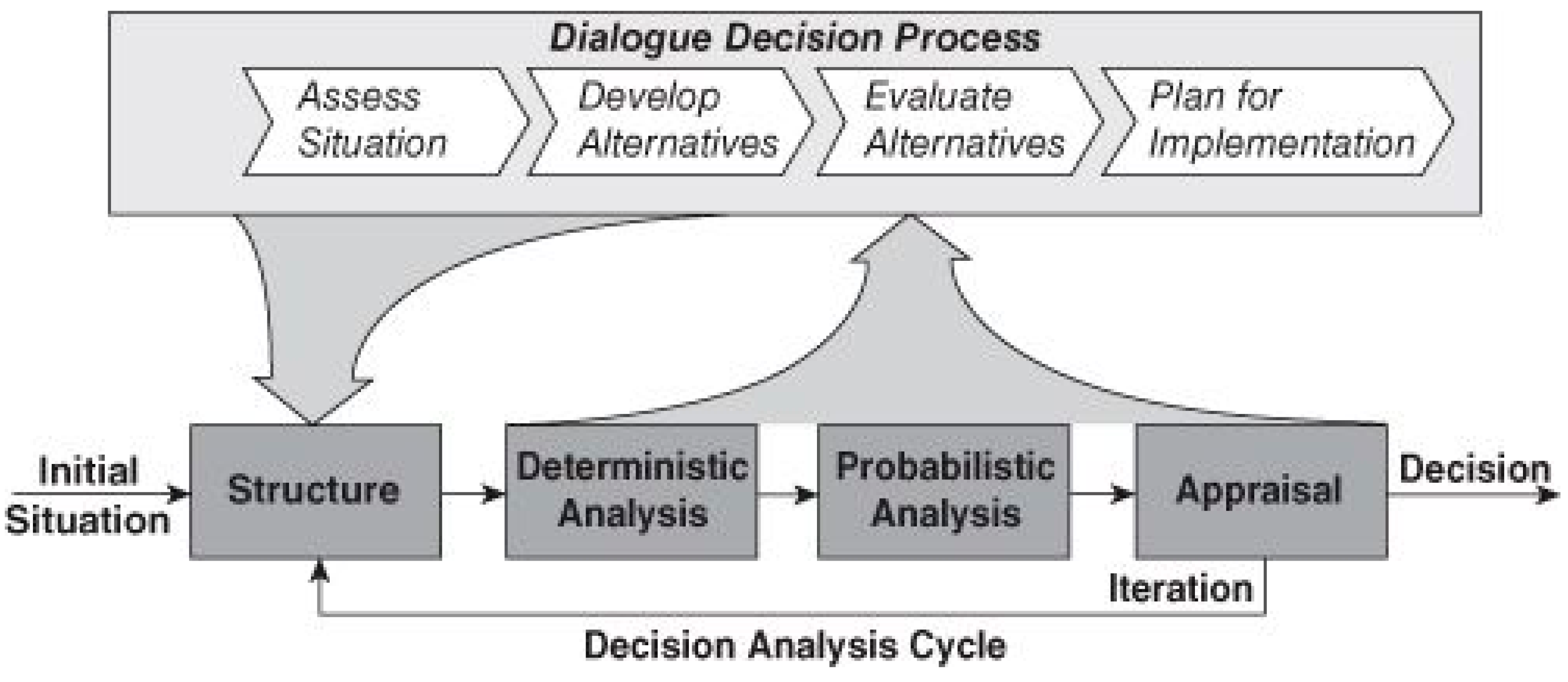
The decision analysis cycle is a common method used to perform an analysis of system design, seen in Figure 1 [6]. This social-technical process uses a dialogue decision process with a decision analysis cycle. The dialogue decision process demonstrates the communication process with the decision makers, while the decision analysis cycle demonstrates the analytical modeling required. Historically, analysts use this cycle with single objective decision analysis, where “appraisal” is analyzing the net present value of the generated alternatives to enable a decision. Many problems cannot be reduced to a single objective and require multiple objective decision analysis (MODA). It is possible to use the decision analysis cycle with MODA. The “appraisal” becomes an evaluation of the system’s aggregated value. Using MODA and separating the system value from cost allows for an affordability analysis during the “appraisal” process. This affordability analysis compares each design alternative by comparing their system performance and lifecycle cost. The most desirable design alternatives are the ones that provide the most value (e.g., system performance, risk, or schedule) at a reasonable cost. The decision maker(s) determine what is “reasonable” during this value versus cost comparison.
3.2. Systems Engineering
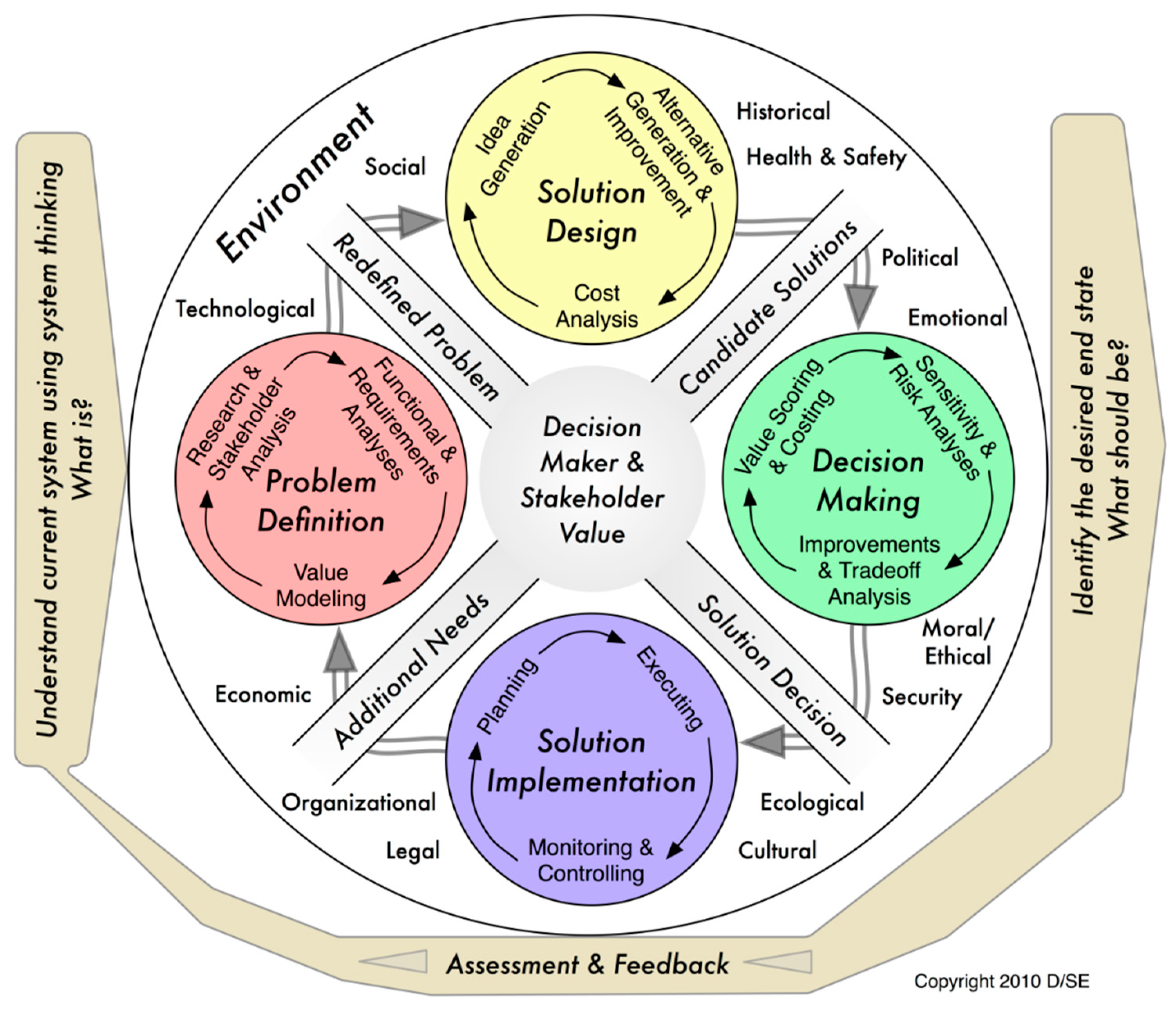
Many system engineering design processes parallel the dialogue decision process. System design requires defining the problem, generating alternatives, evaluating the alternatives to make a decision, and implementing the chosen alternative. One process, seen in Figure 2, is the system decision process (SDP) [7]. Using the SDP’s “problem definition” phase defines the problem through research/stakeholder analysis, functional/requirement analyses, and value modeling. This process produces a redefined problem for alternative generation, called “solution design” in the SDP. Solution design incorporates idea generation, alternative generation and improvement, and a cost analysis. This process produces candidate solutions, which analysts study to help the decision makers select a solution to implement. Analysts use value scoring/costing and sensitivity, risk, and trade-off analyses in the decision-making phase to help select a solution to implement. The solution implementation phase of the SDP incorporates planning, executing, and monitoring/controlling.
An important feature of the SDP is that the process is a cycle. This parallels real world design, since requirements are often updated and additional system needs arise. Cycles also exist in each SDP phase. For example, an analyst would not stop after the original alternatives are developed and improved with a cost analysis. The analyst would continue to generate additional ideas and alternatives based upon the lessons learned and information found from the original analysis. Analysts should repeat the “solution design” analyses based upon the time available to improve the solution. This is true for each SDP phase and the overall SDP. It is still important to maintain project schedule and budget requirements.
3.3. Tradespace Exploration
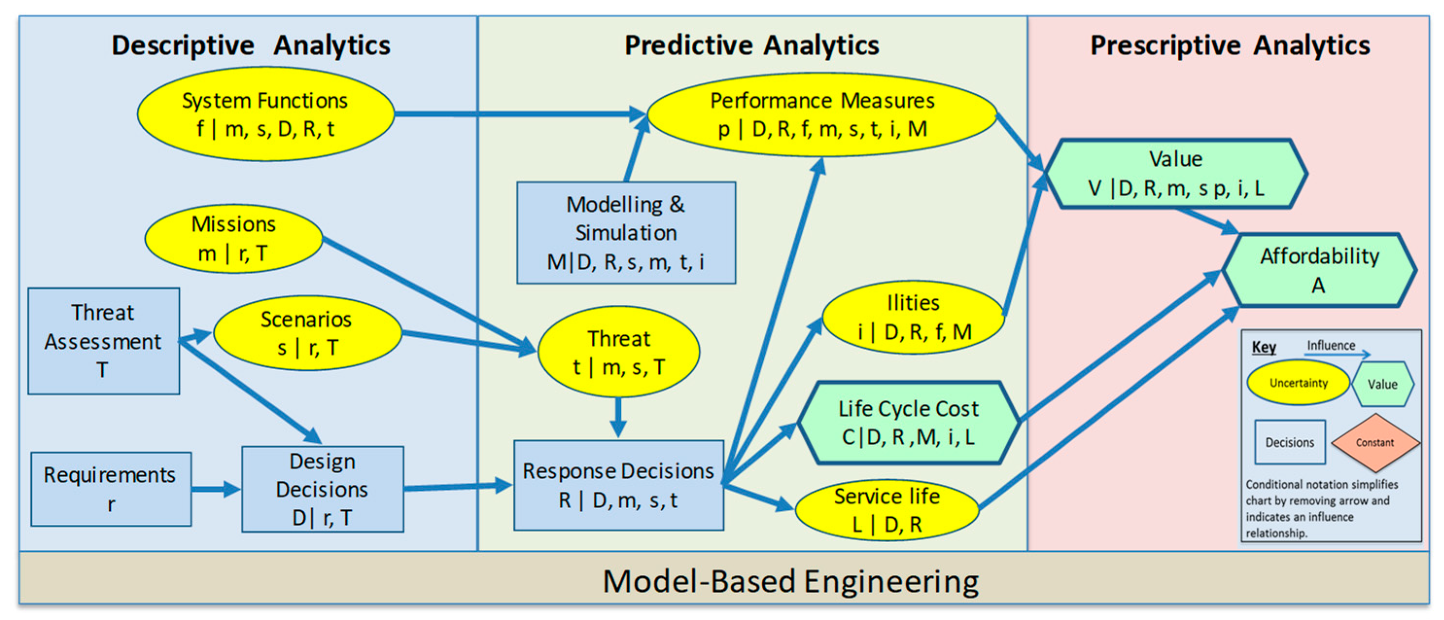
A key feature of the decision analysis cycle is the incorporation of a process with an analytical method. We developed the Integrated Trade-Off Analysis Framework, shown as an influence diagram in Figure 3, to explore the design space for complex engineered systems and evaluate options to make systems more resilient [8]. The Integrated Trade-Off Analysis Framework built upon previous work by Parnell et al. [5], which described how to perform an affordability analysis. The most significant additions to their affordability analysis is the use of MBE/MBSE, the use of the three types of analytics, and the addition of response decisions.
An important note is to incorporate systems thinking when using this framework. As Monat and Gannon [9] point out, systems engineering is different from systems thinking. Incorporating systems thinking will help minimize engineering and design problems by using a holistic view that incorporates relationships [9]. Bonnema and Broenink [10] expand upon system thinking by presenting 12 thinking tracks to help system design (dynamic, feedback, specific-generic, operational, scales, scientific, decomposition-composition, hierarchical, organization, lifecycle, safety, and risk thinking). Using these various types of thinking while implementing the integrated model can help designers and system engineers improve upon their design processes.
An influence diagram represents decision opportunities through decision, uncertainty, constant, and value nodes, with arrows showing the flow of information or probabilistic relationships [6]. Influence diagrams follow a time sequence by viewing the diagram from left to right [6]. The Integrated Trade-Off Analysis Framework uses conditional notation to simplify the graphical representation. For example, the annotation, m|r,T means the missions, m, given the requirements, r, and the threat assessment, T. Small [11] provides a complete definition of each term used in Figure 3.
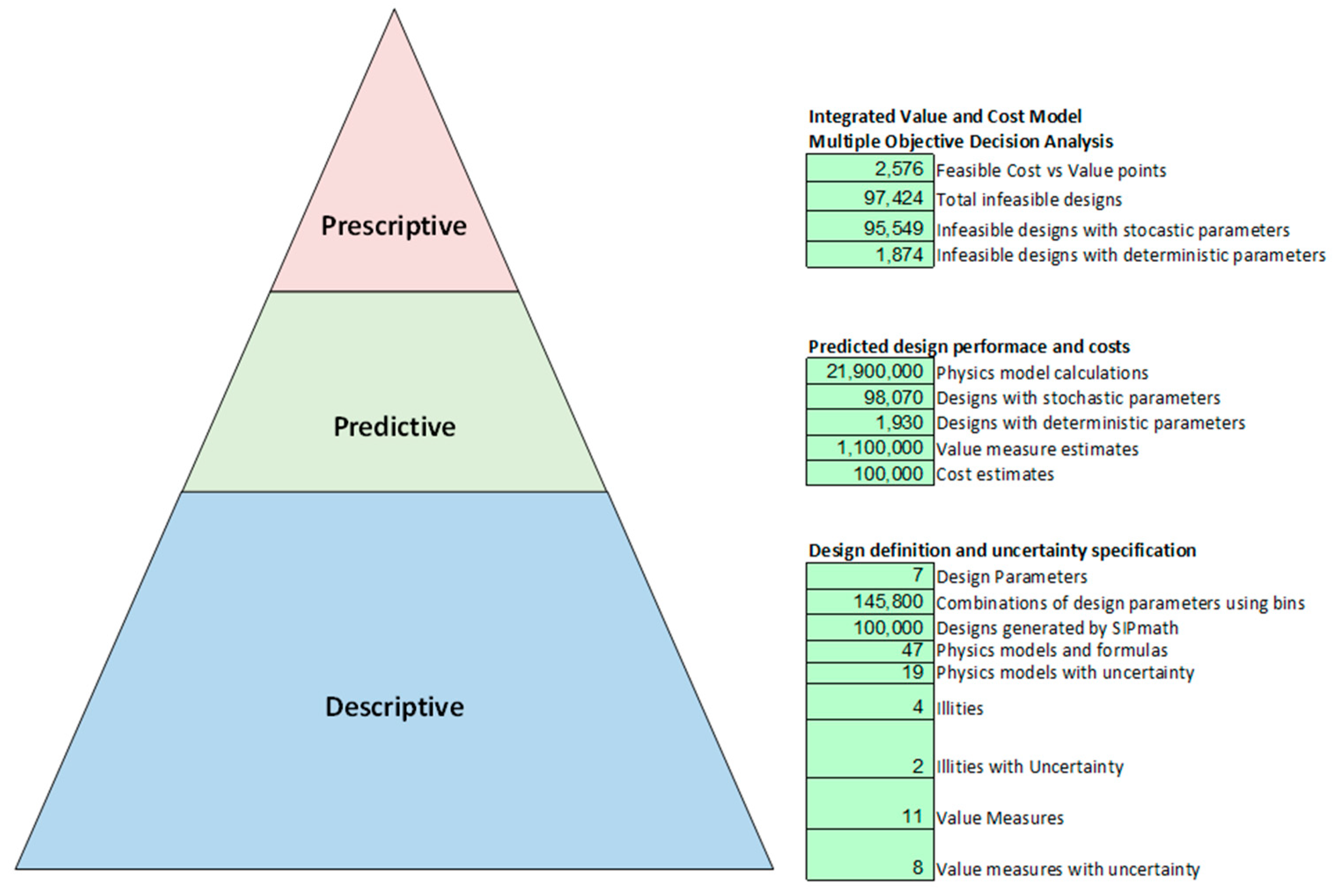
We organize the Integrated Trade-Off Analysis Framework by descriptive, predictive, and prescriptive analytics. Descriptive analytics include the system functions, missions, scenarios, threat assessment, requirement decisions, and design decision. This is because these items use current performance, cost, and risk data. We classify the response decisions, threats, modeling and simulation decisions, performance measures, required “ilities” (developmental, operational, and support requirements [12]), service life, and the lifecycle cost as predictive analytics. Finally, we classify value and affordability as prescriptive analytics. This framework demonstrates the connection between the three types of analytics and their relevance to trade-off analysis in system design.
We propose to use this framework to help system designers with their alternative comparison process. Doing so ensures the thoughtful consideration of each step. Additionally, the Trade-Off Analytics Hierarchy helps communicate their analysis to decision makers. Analysts should think through each of the 15 nodes.
The first step is to determine the desired requirements for the system and to perform a threat/disruption analysis. Analysts decide what threat assessment and requirements to use before the analysis. The requirements change over time as new information becomes available. By using the integrated framework, new or changed requirements update the affordability analysis in near real-time. These requirements affect the system functions and potential system performance. The threat assessment helps the analyst determine internal, external, and environmental adversities/disruptions that could affect the system. Internal adversities consist of disruptions such as a system failure. For example, a lack of maintenance could cause a failure. External adversities are those caused by people/things outside of the system. An example would be an adversary shooting a missile at a UAV. Environmental adversities can include natural disasters. This is important to consider because the environment can greatly affect system performance, especially if it is operating in an environment outside of the intended environment.
The threat assessment affects the mission and scenario assessment for the system. The combination of mission and scenario helps define the intended system task during the operation. Chance nodes depict missions and scenarios in Figure 3. This is because there are unknown missions and scenarios for a given system. Analysts should include, in their model, all relevant missions and scenarios in the model. Modeling and simulation helps analyze the mission and scenarios. We designate modeling and simulation as a decision node, since an analyst must select the appropriate models or simulations used in each analysis.
The requirements and threat assessment affect the possible design decisions and could be options for subsystems, configurations, or parameter changes, to name a few. The design decisions will ultimately affect the overall performance and the affordability analysis, since the system is a combination of the design decisions. An analysis on an overall system will be different from an analysis for a subsystem or component-level design. The design decisions affect most of the nodes in the Integrated Trade-Off Analysis frameworks.
One of the major nodes affected by design decisions is response decisions. Throughout the framework implementation and analysis, new information, including the original affordability analysis, provides insights into the system. These analyses often create opportunities to improve system performance. Response decisions are decisions informed by the threat, missions, and scenarios. Response decisions are how the system plans to maintain the minimum required performance level.
System functions depends upon the missions, scenarios, design and response decisions, and threat assessment. The integrated framework model system functions as a chance node, since how the system is used depends upon the other nodes.
System functions are one of the factors that affect performance measures. The framework models these measures as a chance node, since all prior nodes affect performance. Typically, there are one or more performance measures for the system analysis. These measures are a prediction of the system performance based upon the models and simulations used in the analysis.
We designate models and simulations in the framework as a decision node, since the analyst has to choose what methods or techniques to use in the analysis. These methods and techniques could help analyze the mission, scenario, threat, physics limitations, etc., and predict the performance measures, ilities, and costs.
Developmental, operational, and support requirements define the ilities, which include requirements, such as availability, reliability, or resilience [12]. The integrated framework notes ilities as a chance node. Ilities help capture desired system properties identified by the customer not classified as system requirements [13].
The last chance node affected by system performance, the ilities, and response decisions, is service life. This is a chance node since the service life of the system greatly depends upon what happens to the system during its lifetime.
The first value node is lifecycle cost. This value depends upon the design, ilities, response decision, and the system’s service life. It is usually a prediction based upon modeling and simulation.
Some decision analysts include lifecycle cost as a performance measure that serves as the system value. This is possible, but not recommended. Separating cost provides a more informative analysis to help decision makers select the system with the best performance given their requirements and budget limitations. Value can be determined through one performance measure or many. When we have multiple value measures, we can use multiple objective decision analysis to aggregate individual performance measure values to an overall system value. An additive value model is the most common model.
Finally, the system service life, lifecycle cost, and aggregated system value provides the information necessary to perform an affordability analysis. We perform an affordability analysis using a cost versus value tradespace. An affordability analysis helps the decision maker determine the cost necessary to receive a certain value based upon a given design and can be used in point-based design (PBD) and SBD.
The Integrated Trade-Off Analysis Framework provides a means to perform a tradespace exploration. This framework can use single objective (also called attribute) or multiple objective tradespace exploration (also known as multi-attribute tradespace exploration—MATE [14]).
It is important to note that the Integrated Trade-Off Analysis Framework with MBE can use PBD or SBD. MBE is a required enabler to perform trade-off analysis in near real-time. Without MBE, it is not possible to determine quickly the performance value and cost with many design variables. The larger number of alternatives in SBD require the integrated framework with MBE.
4. Generating and Evaluating Alternatives Using Set-Based Design
4.1. Set-Based Design
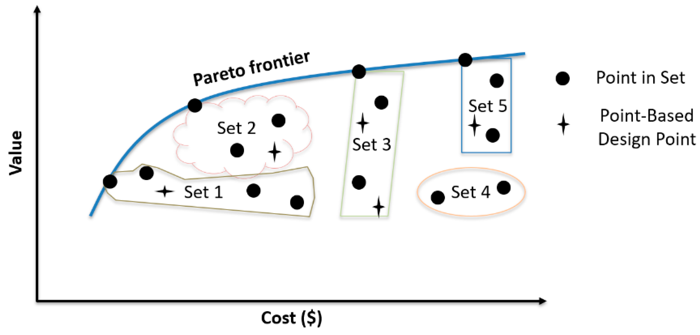
Traditionally, system design consists of groups of experts who collaborate to develop design alternatives based upon their experiences and the system requirements. Modeling and simulation help compare these alternatives and provide information to help select a “best” solution at the end of the process [15]. The literature calls this process point-based design [16]. PBD’s methods have been well-documented in the literature [17,18,19,20,21,22,23,24,25,26,27]. Typically, PBD generates small quantities of design alternatives that may or may not be on the Pareto frontier [2].
Alternatively, SBD explores a large quantity of design alternatives [28]. The most significant difference between PBD and SBD is the number of alternatives explored. SBD explores sets of alternatives, while PBD explores a few alternatives. A set is “a group of design alternatives classified by sharing one or more, but not all, specified design choice(s)” [29]. Wade et al. [29] provides a motivation for SBD, seen in Figure 4.
Set-based concurrent engineering is the most common form of SBD. Set-based concurrent engineering delays decisions, communicates “ambiguously”, and produces large numbers of designs [28]. Singer et al. [30] provided three SBD tenets: “considers large number of designs”, “allows specialist to consider a design from their own perspective and use the intersection between individual sets to optimize a design”, and “establish feasibility before commitment”. While researching Toyota’s set-based concurrent engineering process, Ward et al. [28] found a five-step process to perform SBD:
- Define sets of system alternatives;
- Define sets of subsystem alternatives;
- Analyze parallel subsystems to characterize sets;
- Determine subsystem specifications by using step 3 to narrow feasible design space towards a single solution;
- Maintain solution without change.
Other researchers have found similar steps or characteristics of SBD [15,30,31,32,33,34,35,36,37,38,39,40,41,42,43,44,45,46], but a recent SBD literature search concluded that the literature lacked quantitative, reproducible methods to define, evaluate, and select sets [47]. Specking et al. [47] identified an opportunity to develop techniques for SBD trade-off analysis during early design.
4.2. Implementation
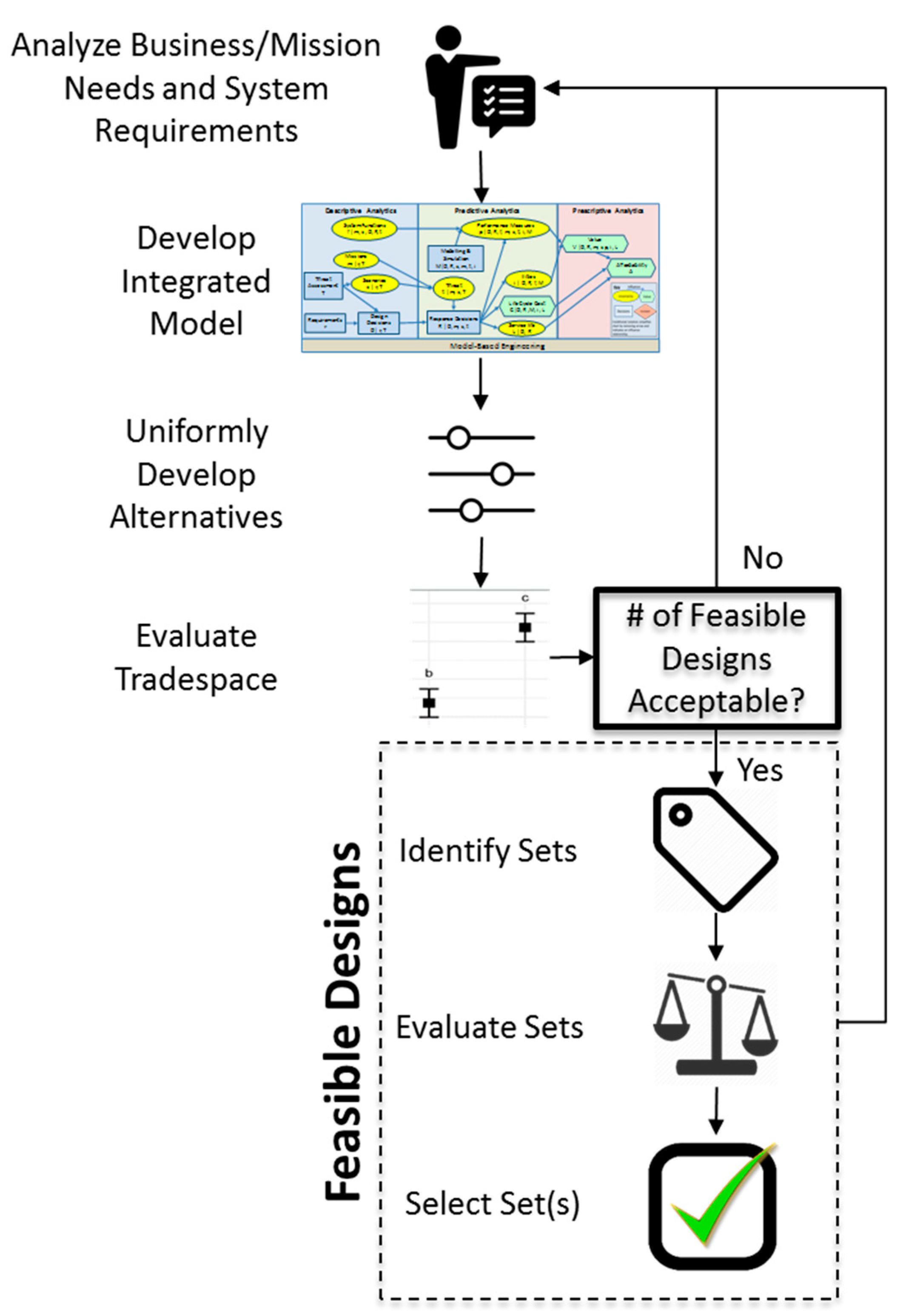
Figure 5 summarizes one approach to perform SBD tradespace exploration during the early design phase. This method starts with gathering the needed information to understand the business/mission needs and system requirements. Analysts should use this information to develop an integrated model. The model must be integrated and use MBE techniques, such as the Integrated Trade-Off Analysis Framework. Without an integrated model that uses MBE techniques, SBD during early design is not possible. The model must be able to update, in near real-time, the effects of the requirements, models, and simulations, on the response variable, such as system performance and cost. This means that the integrated model must be able to determine the response variables for any set of decisions. Analyzing needs/requirements and developing an integrated model are the most important parts of the SBD implementation process. These phases ensure that analysts analyze and solve the right problem in a meaningful manner.
After the integrated model is developed, the potential design alternatives are developed. This step is where SBD differs from PBD. Typically, analysts find “good” points to explore by using optimization techniques, such as a genetic algorithm. A cost analysis on these points determine which designs to carry forward. Instead, the model needs to explore “enough” points to compare sets of points. A design point consists of an option from each decision variable. Sets are comprised of two or more design points that have at least one design option in common. This means that analysts must select one and only one option for each decision variable. Additionally, the options for a decision variable are mutually exclusive and collectively exhaustive.
We develop SBD alternatives by making each decision variable a uniform (discrete or continuous) random variable. This makes each decision option equally likely. The next step is to select the number of desired alternatives to analyze by sampling, from each random variable, a decision option, and compiling them to make an alternative. We recommend repeating this process until you reach a desired number of alternatives. Of course, not all of the potential designs will be feasible. We then use a Monte Carlo simulation, with these points, and the integrated model. Excel tools, such as Probability Management in Excel [48], can perform the uniform sampling and evaluate the feasibility, value, and cost of each design. Finding an “acceptable” number of alternatives is part of the tradespace evaluation step in Figure 5. An integrated framework enables the exploration of all possible combinations of design variables, but this becomes more computationally complex with continuous decision variables and a large number of decision variables. One solution for continuous variables is to bin the variables into distinct discrete ranges. For example, you can round each number to the nearest integer.
The tradespace evaluation step consists of determining feasibility, finding an acceptable number of feasible alternatives to consider, and analyzing the feasible solutions to gain an understanding of how the requirements and decision variables affect the number of feasible alternatives. Feasibility based upon design requirements is important to consider. Infeasible points are not in the tradespace. Therefore, the integrated model should have some means to differentiate feasible from infeasible points and eliminate the infeasible points. A model that differentiates feasible from infeasible designs instead of automatically eliminating the infeasible designs may be the most useful as requirements change. Analysts should reconsider requirements if the number of feasible designs is an unacceptably small number. This could also mean that analysts should reconsider the selected concept or that the current technology limits the selected concept. An integrated framework with SBD can help inform requirements by identifying the number of feasible points with the given requirements. For example, it is possible that a set of design requirements produce a design space with zero feasible alternatives. This means that the design requirements are too constrained. Understanding how each design requirement affects the feasible space helps inform requirement development.
At this point, it may be appropriate to validate the tradespace exploration to find “good” points to compare against the uniformly created solutions. This will require updating the model, while increasing the number of considered solutions and then comparing the new solutions with the “good” points found from the validation process. Analysts should continue to increase the number of feasible alternatives until they find a satisfactory number of points. Finding the Pareto frontier is not always possible due to a non-linear design space. This is why analysts need to trade off computational time and finding enough “good” solutions. This ensures that they find an adequate tradespace. Convergent SBD is an alternative method developed by Wade [49] to find an adequate tradespace.
Performing an analysis on the feasible points will help the analyst gain insights into how the decision variables affect the tradespace. This analysis should include looking at descriptive statistics for each decision variable and response variable and other techniques to understand their relationships. For example, a large wingspan provides capacity for more sensors, but it might not be feasible with a smaller engine, due to a lack of power to propel the added weight. Physics models capture this relationship. This example also demonstrates how analyzing the feasible solutions and response variables can help analysts find trends that are enabled by the various models.
If the number of feasible solutions is sufficient based upon the tradespace exploration validation general process, sets can be identified from the various feasible design points. Identifying what points make up a set is essential to the SBD process. This is essentially how you define the sets, which is difficult since every point contains an option from each decision variable. A set is “a group of design alternatives classified by sharing one or more, but not all, specified design choice(s)” [29]. This means that the selected decision variables are more important decisions than the other decision variables. Defining sets arbitrarily may not provide useful information to design decision makers. To add meaning to the set definition, the concepts of set drivers and set modifiers are useful. Specking et al. [47] defined set drivers as design decisions that drive the performance evaluation metric(s), while set modifiers are all the remaining design decisions that add incremental value. Smaller numbers of set drivers will enable a larger number of points in each set. This is because the decision variables used as set modifiers are what differentiates the points in a set. If only one decision variable is declared a set modifier, then only its decision options are available to be varied in a set. Therefore, fewer set drivers are desirable during the early design stage for set identification. Having fewer set drivers also makes it easier to plot points for visual analysis. Determining the most important decision options for each decision variable is part of the set evaluation and selection stages.
The set evaluation stage should include a dominance analysis to determine what sets are dominated by another set (if any) and other optimization methods, such as applying response surface exploration, system optimization, or system robustness, to find optimal or near optimal decision variable options for a response variable. Dominating sets will have higher value at a lower or equal cost of another set. Similarly, sets that are deemed to be a dominate set, but do not contain the optimal decision variable options, may be eliminated. Just like in the tradespace exploration phase, designers should try to gain insights from the remaining sets, the decision variables that make them, and the feasibility of the remaining space.
Once analysts evaluate the sets, they select one or more sets for further analyses in the set selection phase. One way to select sets is by performing an affordability analysis between design performance and cost on the resulting sets from the set exploration phase. This trade-off between performance and cost helps the decision maker determine the cost necessary to achieve a certain level of design performance.
An important note is that analysts should repeat the tradespace evaluation and set identification, exploration, and selection steps with each model update. Additionally, set identification, exploration, and selection can provide information to help update and/or add additional design requirements. The next design phase uses the remaining sets.
5. UAV Case Study
5.1. Overview
The Integrated Trade-Off Analysis Framework with MSBE and set-based design used by Small [11] on a UAV case study started with the analysis of alternatives originally performed by Cilli [50] for the Army Armament Research Development Engineering Center (ARDEC). Small worked with Cilli to improve the original analysis of alternative by adding design choices and upgrading the physics, value (system performance), and lifecycle cost models. He went through nine iterations and used multiple subject matter experts [11]. His final model accounted for uncertainty in performance measures, cost, and decision makers’ preferences, and connected design parameters, physic models, a multiple objective decision analysis (MODA) value model, and a lifecycle cost model to create the tradespace (design cost versus performance) in Excel.
The final model contained 7 design decisions (length of wingspan, type of engine, operating altitude, electro-optical (EO) sensor pixel width, EO sensor field of view, infrared (IR) sensor pixel width, and IR sensor field of view) used 47 physics models to calculate 11 performance measures and produce 2576 feasible designs that considered uncertainty (2526 deterministic designs). Small [11] used Monte Carlo simulation with the Excel-based Probability Management™ tool to analyze 100,000 design alternatives in near real-time. This produced 100,000 cost estimates, 21,900,000 physics-based model calculations, and 1,100,000 performance measure estimates [11]. Small [11] captures the complexities of the UAV case study by using the Trade-Off Analytics Hierarchy seen in Figure 6. Specking et al. [3] used the same case study to show the validity of the Integrated Trade-Off Analysis Framework with SBD for tradespace exploration.
5.2. Implementation of the Integrated Trade-Off Analysis Framework
All aspects of the Integrated Trade-Off Analysis Framework are evident in Small’s [11] model. A combination of each of the 7 design decisions‘ options make up the design alternatives. The mission and scenario for the designed UAV was to perform surveillance. A value hierarchy captured the purpose, functions, objectives, and performance measures for the UAV. This value hierarchy assisted the creation of a multiple objective decision analysis model, which used an additive value function and a swing weight matrix. The swing weight matrix captured decision makers’ preference based upon the mission, scenario, and threat. We scored the performance measures for each alternative by using physics models. A value curve transformed each score into a value where the minimum accepted values for each performance measures’ value curve comes from the design requirements with the ideal value assigned 100. Additionally, the “ilities” affect the score of certain performance measures. The UAV model considered availability, reliability, survivability, and restoration to help create resilient response decisions. The aggregate of all performance measures found by the additive value model produces the aggregated performance (value) of the system. The UAV case study used this value with a lifecycle cost model to perform an affordability analysis, which helps decision makers select designs that maximizes performance while minimizing cost.
5.3. Integration of Set-Based Design
The Integrated Trade-Off Analysis Framework completes the first 2 steps of the SBD tradespace exploration implementation process (analyze business/mission needs and system requirements and develop integrated model). Small [11] developed alternatives uniformly by making each design decision a uniform random variable that varied based upon its decision options. For example, Small [11] transformed wingspan into a continuous uniform random variable from 2 to 12, and engine type a discrete uniform random variable with options E or P (binary). He used this method with Probability Management™ in Excel to create 100,000 design alternatives. The integrated framework with MBE was used to evaluate the 100,000 design alternatives to create the feasible tradespace (2576 designs), which were deemed to be an acceptable number of feasible designs.
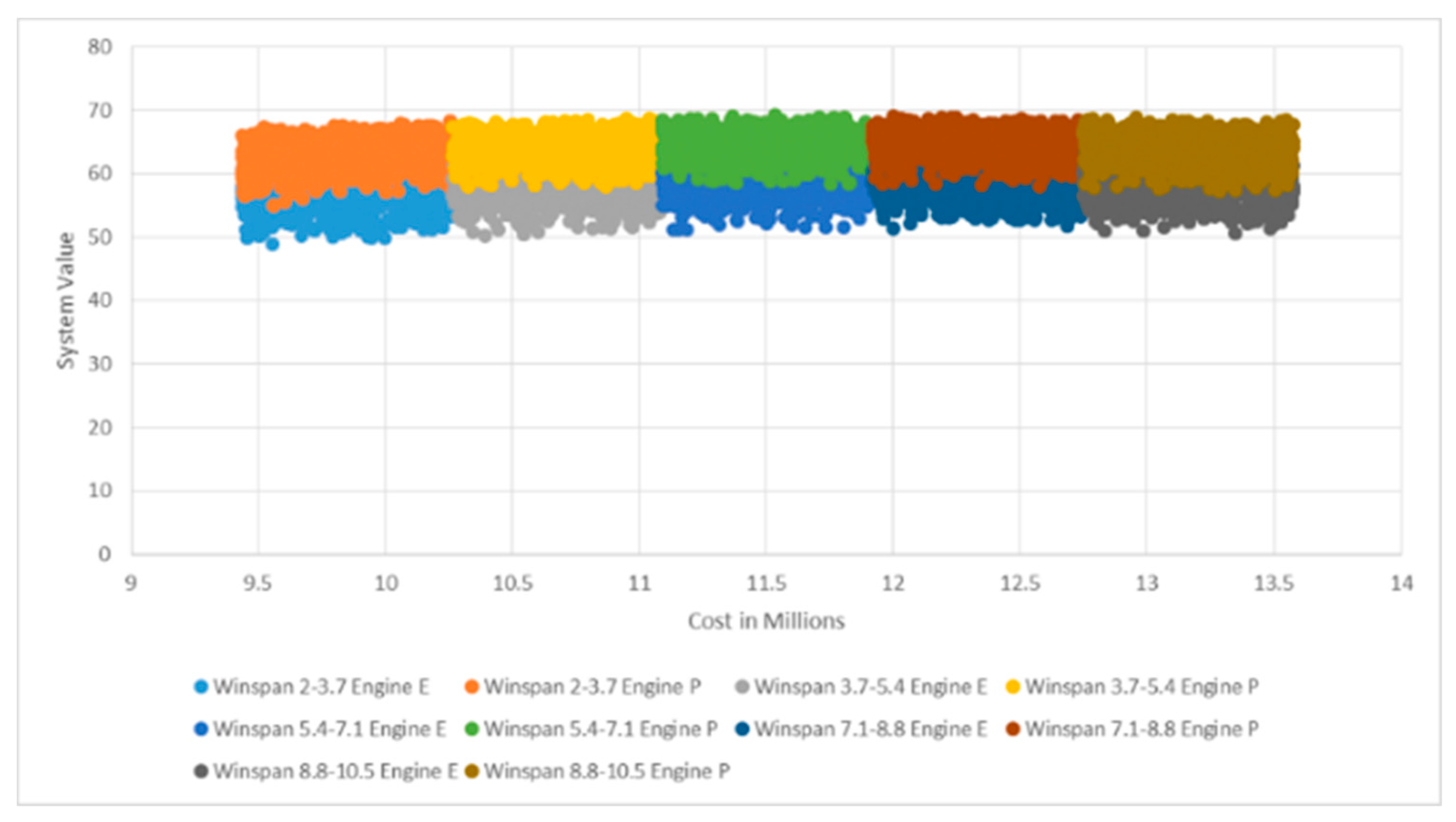
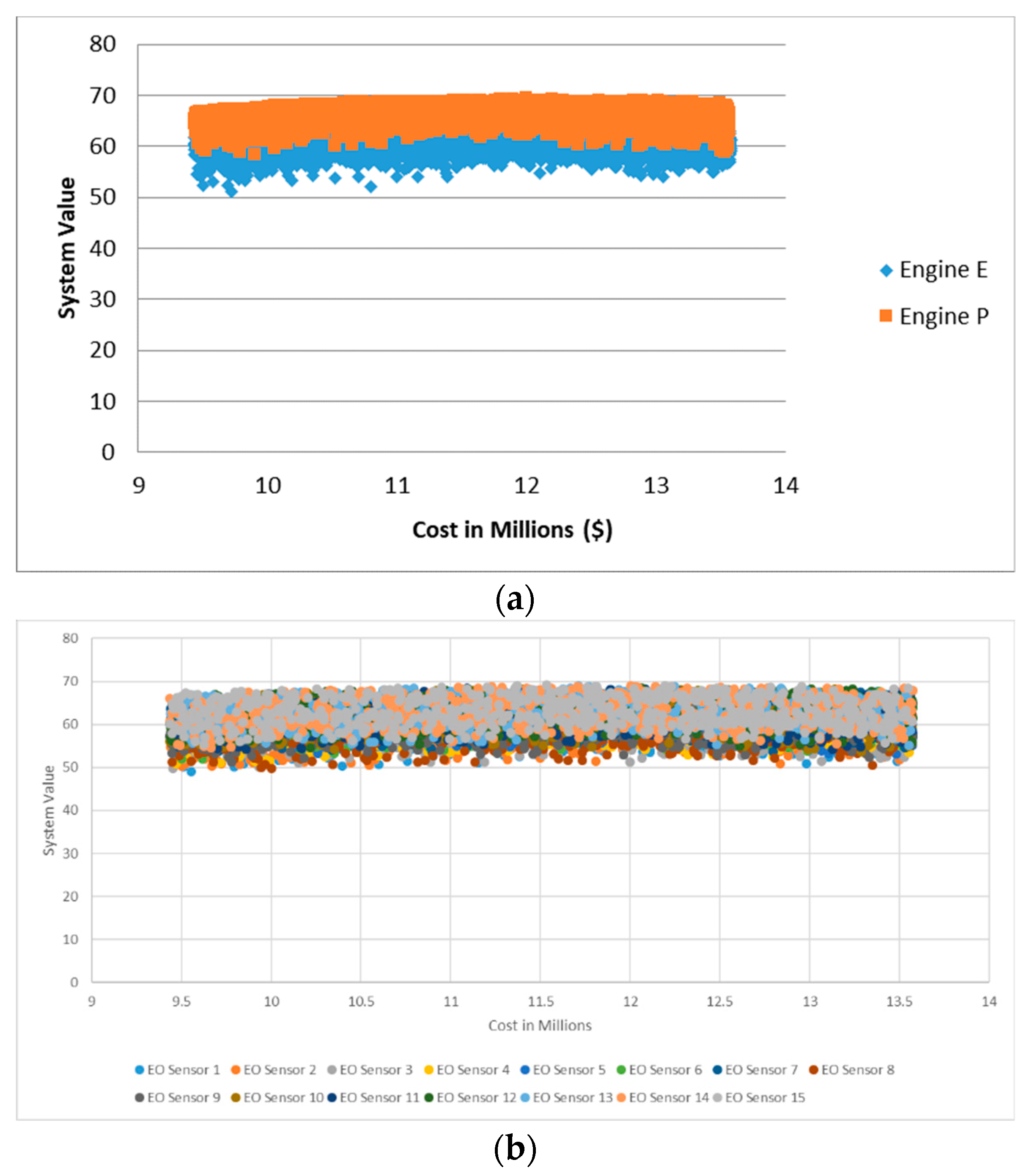
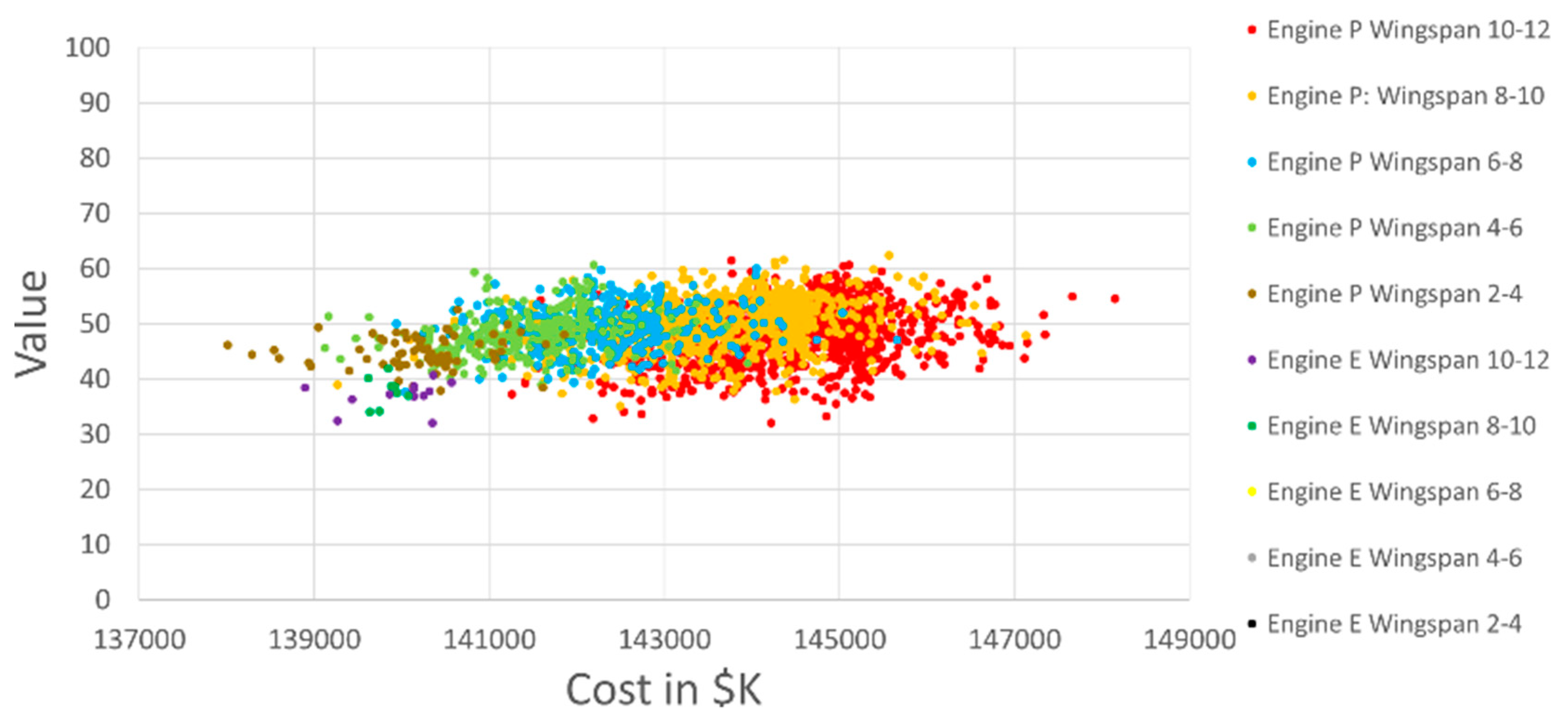
The next step was to analyze these designs to determine the set drivers for set identification. A visual heuristic was used on a previous model with subject matter expertise to determine that the type of engine and length of wingspan were the set drivers, seen in Figure 7. These set drivers can change depending upon the model. Small [11] should have updated his set drivers by performing the set identification analyses after each model update. The approach used was to graph the cost versus value points based upon each decision variable and visually inspect the graph to determine its effect. He used questions, such as how much overlap existed among the defined sets or did the define sets make a partition. Figure 8 demonstrates the difference between a good (engine type) and worse (EO sensor) visual result. He combined variables with little overlap or apparent sets with another decision variable. Subject matter expertise helped select the combined decision variables. He used engine type and wingspan as the set drivers from this analysis. The probabilistic model used the same set drivers, seen in Figure 9.
The problem with this analysis is that partitioning is typically not possible. A non-overlapping partition of the design space would enable an easier set selection process. For example, a non-partitioned tradespace might require the selection of more than one design set because the desired value/cost range consists of points from multiple sets. Additionally, how the sets are colored and how the design points overlap plays an important role. It is hard to determine the range of the sets in the background with just a visual inspection. Sets of points in the background can extend to the same level of value as the ones in the forefront. These points require further investigation. Background points with maximum value levels lower than the ones in the forefront are dominant, and can be eliminated in the set evaluation or selection stages. For example, the sets that range from 55 to 70 on top in Figure 7 appear to dominate the bottom ones, but it is impossible to determine overlap without further investigation. This is why the previous stage of tradespace exploration is vital. An analyst has to investigate the decision variables, response variables (performance and lifecycle cost), and their relationships.
Analysts can consider sets with higher performance as driving system value, but it is impossible to know if the overall decision variable drives value. For example, decision option “A” of design decision 2 could drive value upwards, but design decision 2, overall, does not drive value when compared to the other decision variables. Knowing which decision options produce higher values is important in the set selection stage of Figure 5.
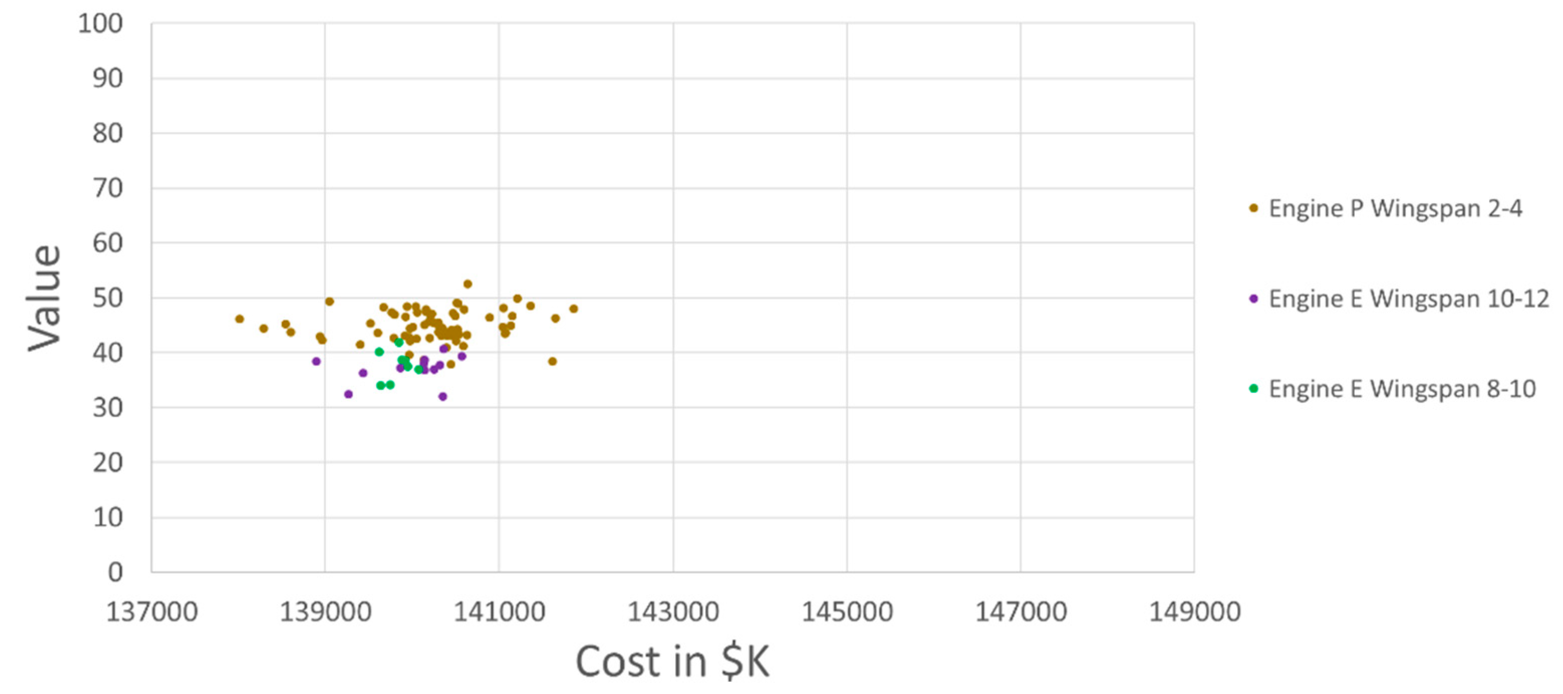
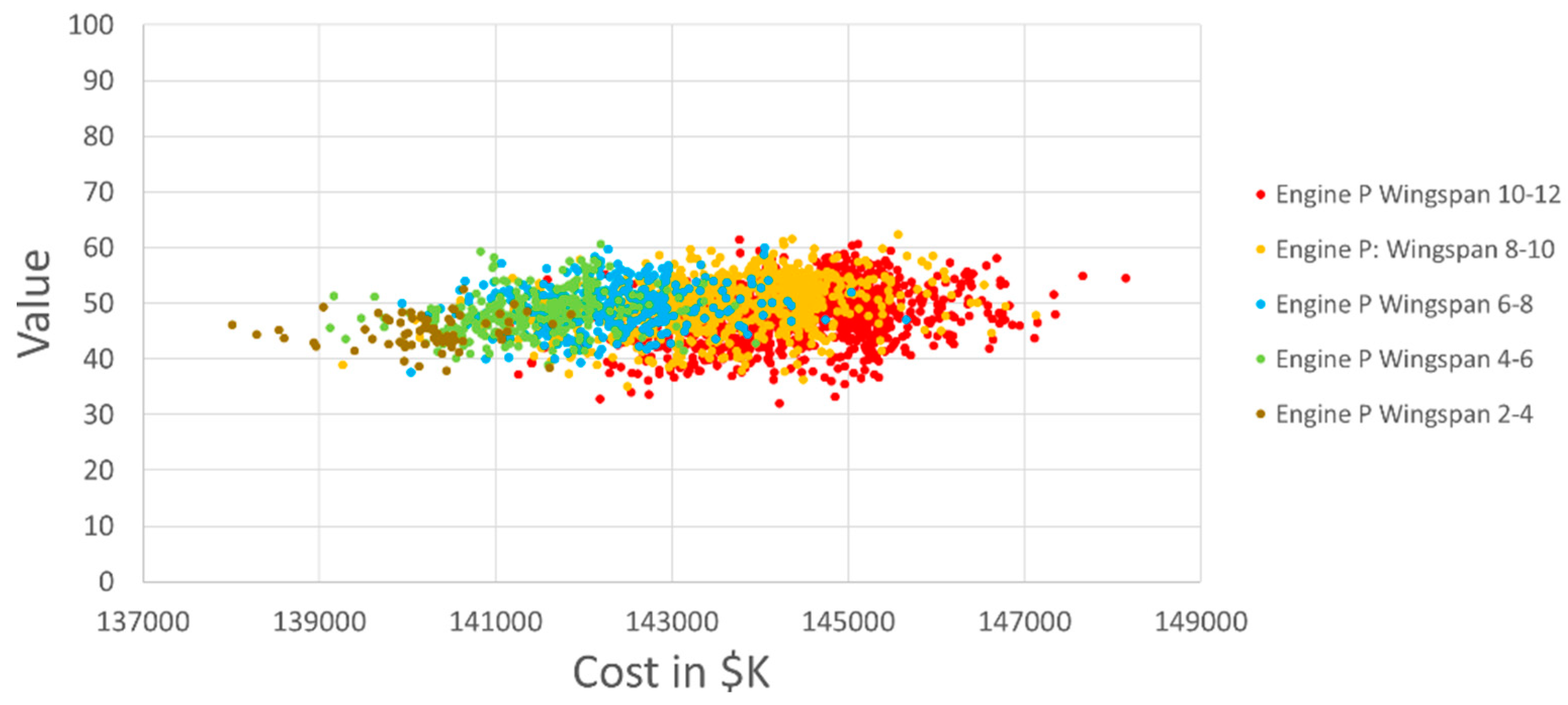
Small [11] focused on creating the integrated model to evaluate UAV designs. We performed a simple evaluation analyzing dominance and feasibility. This analysis found that engine type E with wingspans between greater than 2 and less than 8 did not produce feasible designs. We then performed a dominance analysis on the remaining sets. This involved doing a set-by-set comparison of the 10 set driver combinations for system performance (value). For example, engine type P with wingspan of 2 to 4 dominated in value engine type E with wingspan width of 8 to 10 and engine type E with wingspan 10 to 12, seen in Figure 10. Dominance does not eliminate the remaining five sets, seen in Figure 11.
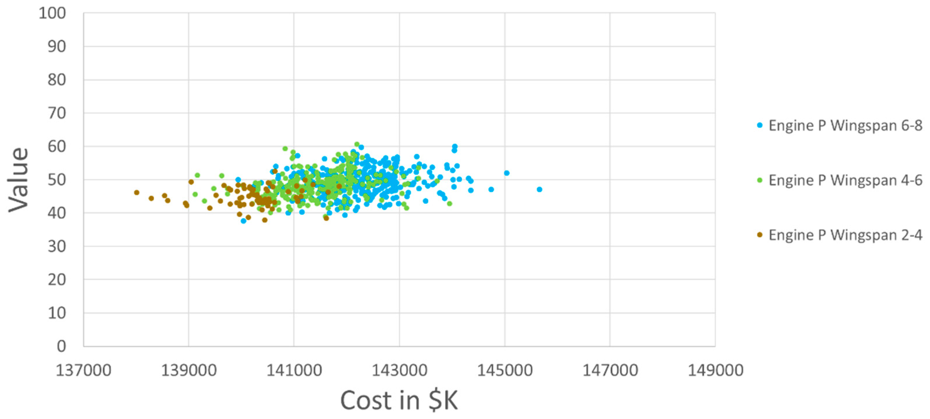
Descriptive statistics provides additional information about the remaining sets, as shown in Table 1. It is evident that engine P with a wingspan of 8 through 12 could be eliminated due to its large standard deviation in value and cost. Additionally, engine P with wingspan of 8 through 12 has a mean value and cost that is close to or better than the remaining sets, with a similar max value at a lower max cost. The three remaining sets (engine P with wingspan from 2 to 8) are presented to the decision maker as the recommend sets to carry forward to the next design phase for further analysis, seen in Figure 12. The three selected sets reduce the total feasible designs from 2537 to 671.
5.4. Tradespace Validation
Model validation and verification is vital to ensure trustworthy and quality results. Analysts need to demonstrate that their model adequately explores the design space. Specking et al. [3] hypothesized that a tradespace exploration method that uses SBD can be validated by using optimization techniques to find the efficient frontier. A valid model would find design points on the efficient frontier.
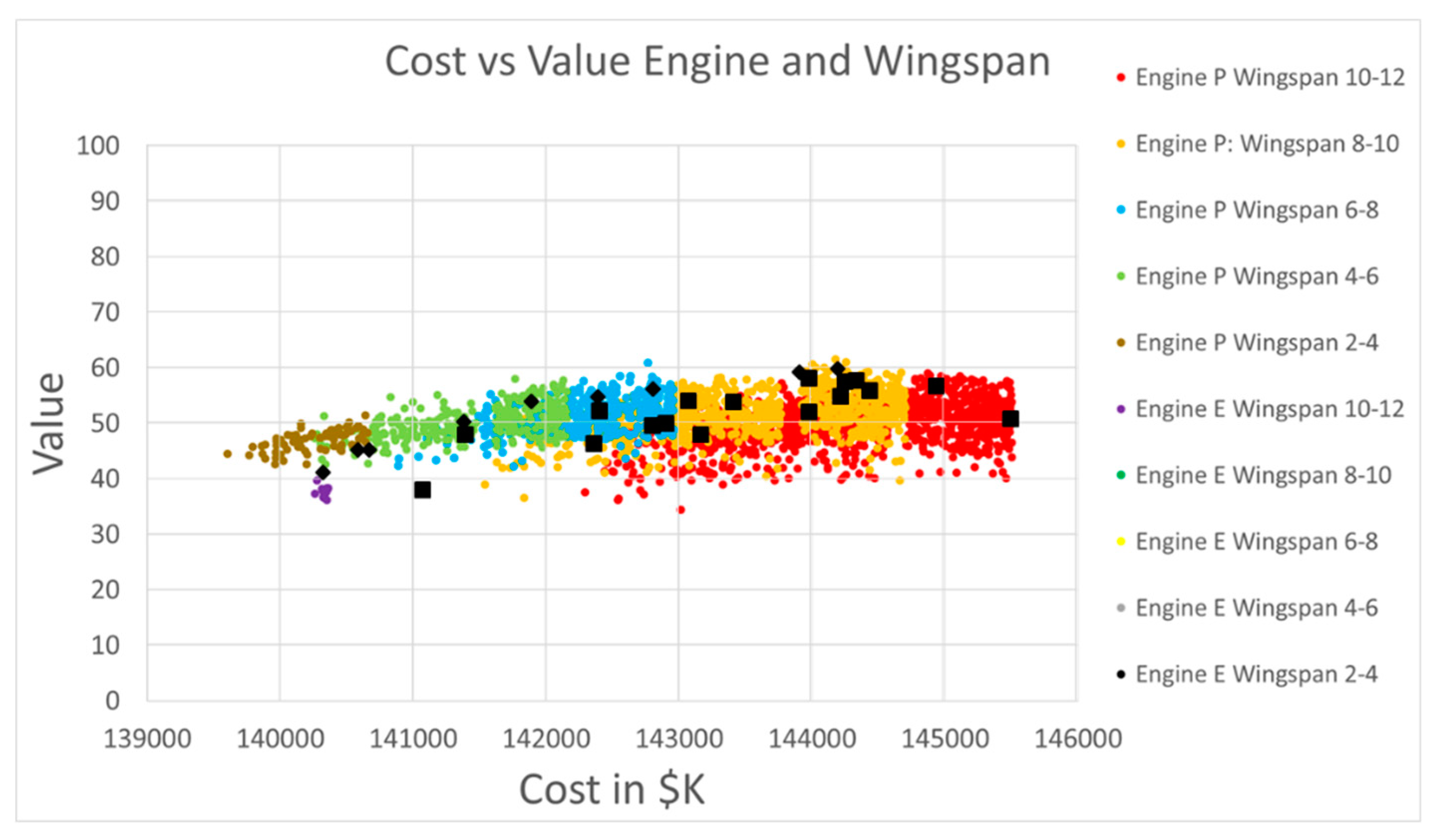
Specking et al. [3] validated an application of SBD using the Integrated Trade-off Analysis Framework by using a genetic algorithm on Small’s [11] unmanned aerial vehicle case study. The genetic algorithm found 26 unique “good” designs, seen as black squares in Figure 13. We compared these “good” designs with the 2526 feasible designs found by Small’s [11] deterministic model that used the Integrated Trade-off Analysis Framework. Small’s [11] tradespace exploration adequately explored the design space since the original tradespace exploration found 189 designs that dominated the 26 genetic algorithm points.
6. Summary and Future Work
Exploring the tradespace to find cost-effective designs in the early design phase is important for analysts, designers, system engineers, project managers, and decision makers. This is vital for the design of complex systems and systems-of-systems to ensure selected designs have a high probability of feasibility before starting the next design phase. This study proposes an early design phase SBD implementation methodology and demonstrates how SBD enabled by MBSE and an integrated framework provides an enhanced TSE that can inform system design requirements and help decision makers select high performing designs at an affordable cost. Specifically, this paper (1) provides an overview of TSE and SBD, (2) describes the Integrated Trade-off Analysis Framework with MBSE, (3) describes a methodology to implement SBD in the early design phase, and (4) demonstrates the techniques used in this paper through a UAV case study. The methodology description, with the example, provides a reproducible means to perform this method of tradespace exploration that uses an integrated framework (Integrated Trade-off Analysis Framework) with MBSE and SBD. Industry and governmental organizations can improve their early design phase analyses by using our SBD implementation process in their product’s early design phase. Our process helps increase the number of considered alternatives, provides a means to compare those alternatives, and analyzes the effects of design requirements on the feasible design space.
Model-based system engineering techniques enable the use of an integrated framework and set-based design. Without this type of modeling with an integrated model, there is not a means to update in near-real time the response variables (system performance and life-cycle cost) based upon design decisions (inputs) and/or requirement changes. This near-real time update with SBD and an integrated model with MBSE provides an improved decision analysis to evaluate and select alternatives in early design. In the UAV example, the Integrated Trade-off Analysis Framework uses model-based techniques to provide a score for each performance measure for each design alternative in a multiple objective decision analysis model. MBSE techniques update the life-cycle cost model based upon the design decisions. Using MBSE techniques increase the amount of time spent in the early design phase, but will allow systems engineers to rapidly respond to changes in requirements or new information about performance. This has the potential to help system engineers develop better systems with fewer problems while staying within the project’s schedule and cost [1]. Additionally, using MBSE with an integrated framework provides a means to inform requirement development based upon how the requirement changes affect the feasible design space.
The Integrated Trade-off Analysis Framework provides the traceability needed to help analysts and system engineers better explain the models used to select a design or sets of designs for the next design phase. By using this framework, analysts, designers, system engineers, project managers, and decision makers can improve their design decisions. Analysts can use the Integrated Trade-off Analysis Framework as a guide, but should create an influence diagram based upon the needs and requirements of the desired future system. This means that the newly created diagram should be a representation of the domain and future system.
SBD used with an integrated framework with MBSE explores a larger quantity of feasible designs compared to traditional point-based design methods and many better feasible designs. The SBD implementation method provides a repeatable process to incorporate SBD in early design analyses. The first 2 steps (analyze needs and requirements and develop an integrated model) is where a majority of time should be spent. This will help ensure that a type 3 error does not occur (wrong problem solved) and the selection of a realistic solution. It is possible to use other means to develop alternatives, but uniformly creating them increases the probability that a larger number of feasible solutions will be developed. SBD, with an integrated framework with MBSE, allows for the comparison of any number of design alternatives up to all possible combinations of design decisions. This is often not realistic due to computational complexities and the runtime required to examine all possible combinations. Increasing the number of design decisions increases the computational complexity. Additionally, increasing model fidelity will increase computational complexity and the required runtime. Analysts should dedicate time when evaluating the tradespace (step 4) and sets (step 6). A good analysis can provide useful information that updates the business/mission needs and system requirements. Step 4 can also provide insight into the design decisions and their options. Analysts should be careful when selecting how to categorize sets in step 5. Analysts should categorize based upon set drivers to prevent giving importance to a decision variable that does not add more value when considering the model’s response variables. After categorizing sets, analysts should spend time evaluating them to understand the characteristics that makes up that set and what drives the response variable. This information with feasibility and dominance will help analysts select sets to propose to the decision makers to move to the next design phase.
This work provides a foundation to implement SBD in early design, but future research is needed to enhance SBD techniques in early design. We need to implement greater fidelity models with the SBD and MBSE integrated model to determine its effect on the design space, which will increase the computational complexity of the overall model. Additionally, we need to develop and explore better techniques to help identify, evaluate, and select sets. Finally, we need to identify other MBSE techniques that could enhance the analysis of alternatives with SBD in the early design phase.
Author Contributions
Conceptualization, E.S.; Formal analysis, E.S.; Funding acquisition, G.P. and E.P.; Investigation, E.S.; Methodology, E.S.; Project administration, G.P.; Resources, G.P. and E.P.; Validation, E.S.; Visualization, E.S.; Writing—original draft, E.S.; Writing—review & editing, G.P., E.P. and R.B.
Funding
This research was funded by the United States Army Engineering Research and Development Center (ERDC) as part of an Engineering Resilient Systems (ERS) research project. Part of this research was submitted to ERDC as part of a technical report [3].
Conflicts of Interest
ERDC provided input and direction through quarterly meetings. ERDC personnel provided a review and comments before submission.
References
- Guo, Z.X. Co-Evolution of Complex Aeronautical System and Complex System Engineering. Presented at the 2018 INCOSE International Symposium, Washington, DC, USA, 9 July 2018. [Google Scholar]
- Specking, E.; Parnell, G.S.; Pohl, E.; Buchanan, R. A Foundation for System Set-Based Design Trade-off Analytics. In Proceedings of the American Society for Engineering Management 2018 International Annual Conference, Coeur d’Alene, ID, USA, 17–20 October 2018. [Google Scholar]
- Specking, E.; Small, C.; Wade, Z.; Parnell, G.; Cottam, B.; Pohl, E. Final Technical Report Task 2: Design Space Exploration; The U.S. Army Engineering Research and Development Center: Vicksburg, MS, USA, September 2018. [Google Scholar]
- Definition of Tradeoff Analysis. Available online: http://www.businessdictionary.com/definition/tradeoff-analysis.html (accessed on 30 January 2018).
- Parnell, G.S. Trade-Off Analytics: Creating and Exploring the System Tradespace; John Wiley & Sons: Hoboken, NJ, USA, 2016. [Google Scholar]
- Parnell, G.S.; Bresnic, T.A.; Tani, S.N.; Johnson, E.R. Handbook of Decision Analysis; John Wiley & Sons: Hoboken, NJ, USA, 2013. [Google Scholar]
- Parnell, G.S.; Driscoll, P.J.; Henderson, D.L. Decision Making in Systems Engineering and Management; John Wiley & Sons: Hoboken, NJ, USA, 2011; Volume 81. [Google Scholar]
- Small, C.; Parnell, G.; Pohl, E.; Goerger, S.; Cottam, B.; Specking, E.; Wade, Z. Engineering Resilience for Complex Systems. In Disciplinary Convergence in Systems Engineering Research; Madni, A., Boehm, B., Ghanem, R., Erwin, D., Wheaton, M., Eds.; Springer International Publishing: Cham, Switzerland, 2018. [Google Scholar]
- Monat, J.; Gannon, T. Applying Systems Thinking to Engineering and Design. Systems 2018, 6, 34. [Google Scholar] [CrossRef]
- Bonnema, G.M.; Broenink, J.F. Thinking tracks for multidisciplinary system design. Systems 2016, 4, 36. [Google Scholar] [CrossRef]
- Small, C. Demonstrating Set-Based Design Techniques—A UAV Case Study. Master’s Thesis, University of Arkansas, Fayetteville, AR, USA, 2018. [Google Scholar]
- INCOSE. Systems Engineering Handbook: A Guide for System Life Cycle Processes and Activities, 4th ed.; John Wiley& Sons: Hoboken, NJ, USA, 2015. [Google Scholar]
- Lee, J.Y.; Collins, G.J. On using ilities of non-functional properties for subsystems and components. Systems 2017, 5, 47. [Google Scholar] [CrossRef]
- Ross, A.M.; Stein, D.B.; Hastings, D.E. Multi-Attribute Tradespace Exploration for Survivability. J. Spacecr. Rocket. 2014, 51, 1735–1752. [Google Scholar] [CrossRef] [Green Version]
- Liker, J.K.; Sobek, D.K.; Ward, A.C.; Cristiano, J.J. Involving suppliers in product development in the United States and Japan: Evidence for set-based concurrent engineering. IEEE Trans. Eng. Manag. 1996, 43, 165–178. [Google Scholar] [CrossRef]
- Specking, E.; Whitcomb, C.; Parnell, G.; Goerger, S.; Pohl, E.; Kundeti, N. Trade-off Analytics for Set-Based Design. In Proceedings of the Design Sciences Series: Set Based Design, Washington, DC, USA, 26–27 September 2017. [Google Scholar]
- Lasdon, L.S. Optimization Theory for Large Systems; Macmillan: New York, NY, USA, 1970. [Google Scholar]
- Wismer, D.A. Optimization Methods for Large-Scale Systems ... with Applications; McGraw-Hill Companies: New York, NY, USA, 1971. [Google Scholar]
- Sobieszczanski-Sobieski, J.; Barthelemy, J.-F.M.; Giles, G.L. Aerospace Engineering Design by Systematic Decomposition and Multilevel Optimization; National Aeronautics and Space Administration, Langley Research Center: Hampton, VA, USA, 1984.
- Azarm, S.; Li, W.-C. Multi-level design optimization using global monotonicity analysis. J. Mech. Transm. Autom. Des. 1989, 111, 259–263. [Google Scholar] [CrossRef]
- Haimes, Y.Y. Hierarchical Multiobjective Analysis of Large-Scale Systems; Hemisphere Pub.: New York, NY, USA, 1990. [Google Scholar]
- Sobieszczanski-Sobieski, J. Sensitivity Analysis and Multidisciplinary Optimization for Aircraft Design: Recent Advances and Results. In Proceedings of the 16th Congress International Council of the Aeronautical Sciences (ICAS), Jerusalem, Israel, 28 August–2 September 1988. [Google Scholar]
- Sheridan, D.; Clark, D.; Jones, R.; Fein, J. The ASSET Program—A Current Navy Initiative. In Proceedings of the SNAME Spring Meeting, Los Angeles, CA, USA, 28 July–12 August 1984. [Google Scholar]
- Cramer, E.J.; Frank, P.D.; Shubin, G.R.; Dennis, J.; Lewis, R. On alternative problem formulations for multidisciplinary design optimization. In Proceedings of the 4th Annual AIAA/Air Force/NASA/OAI Symposium on Multidisciplinary Analysis and Optimization, Cleveland, OH, USA, 21–23 September 1992. [Google Scholar]
- Davis, W. A generalized decomposition procedure and its application to engineering design. J. Mech. Des. 1978, 100, 739–746. [Google Scholar] [CrossRef]
- Johnson, R.; Benson, R. A basic two-stage decomposition strategy for design optimization. J. Mech. Transm. Autom. Des. 1984, 106, 380–386. [Google Scholar] [CrossRef]
- Johnson, R.; Benson, R. A multistage decomposition strategy for design optimization. J. Mech. Transm. Autom. Des. 1984, 106, 387–393. [Google Scholar] [CrossRef]
- Ward, A.; Liker, J.K.; Cristiano, J.J.; Sobek, D.K. The second Toyota paradox: How delaying decisions can make better cars faster. Sloan Manag. Rev. 1995, 36, 43. [Google Scholar]
- Wade, Z.; Parnell, G.; Goerger, S.; Pohl, E.; Specking, E. Designing Engineered Resilient Systems Using Set-Based Design. In Proceedings of the 16th Annual Conference on Systems Engineering Research, Charlottesville, VA, USA, 8–9 May 2018. [Google Scholar]
- Singer, D.J.; Doerry, N.; Buckley, M.E. What Is Set-Based Design? Nav. Eng. J. 2009, 121, 31–43. [Google Scholar] [CrossRef]
- Burrow, J.; Doerry, N.; Earnesty, M.; Was, J.; Myers, J.; Banko, J.; McConnell, J.; Pepper, J.; Tafolla, C.T. Concept Exploration of the Amphibious Combat Vehicle. Available online: http://doerry.org/Norbert/papers/20140726ConceptExplorationoftheAmphibiousCombatVehicle.pdf (accessed on 30 January 2018).
- Finch, W.W.; Ward, A.C. A set-based system for eliminating infeasible designs in engineering problems dominated by uncertainty. In Proceedings of the 1997 ASME Design Engineering Technical Conferences, Sacramento, CA, USA, 14–17 September 1997. Paper No. DETC97/DTM-3886. [Google Scholar]
- Ford, D.N.; Sobek, D.K. Adapting real options to new product development by modeling the second Toyota paradox. IEEE Trans. Eng. Manag. 2005, 52, 175–185. [Google Scholar] [CrossRef]
- Ghosh, S.; Seering, W. Set-Based Thinking in the Engineering Design Community and Beyond. In Proceedings of the ASME 2014 International Design Engineering Technical Conferences and Computers and Information in Engineering Conference, Buffalo, NY, USA, 17–20 August 2014; p. V007T07A040. [Google Scholar]
- Kim, W. A Framework for Set-Based Manufacturing Analysis and Visual Feedback. Ph.D. Thesis, Pennsylvania State University, Old Main, PA, USA, 2015. [Google Scholar]
- Madhavan, K.; Shahan, D.; Seepersad, C.C.; Hlavinka, D.A.; Benson, W. An industrial trial of a set-based approach to collaborative design. In Proceedings of the ASME 2008 International Design Engineering Technical Conferences and Computers and Information in Engineering Conference, Brooklyn, NY, USA, 3–6 August 2008; pp. 737–747. [Google Scholar]
- Malak, R.J.; Aughenbaugh, J.M.; Paredis, C.J. Multi-attribute utility analysis in set-based conceptual design. Comput.-Aided Des. 2008, 41, 214–227. [Google Scholar] [CrossRef]
- McKenney, T.A.; Kemink, L.F.; Singer, D.J. Adapting to Changes in Design Requirements Using Set-Based Design. Nav. Eng. J. 2011, 123, 66–77. [Google Scholar] [CrossRef] [Green Version]
- McKenney, T.A.; Singer, D.J. Determining the influence of variables for functional design groups in the set-based design process. In Proceedings of the American Society of Naval Engineers Day, Arlington, VA, USA, 9–10 February 2012. [Google Scholar]
- Mebane, W.L.; Carlson, C.M.; Dowd, C.; Singer, D.J.; Buckley, M.E. Set-Based Design and the Ship to Shore Connector. Nav. Eng. J. 2011, 123, 79–92. [Google Scholar] [CrossRef] [Green Version]
- Nahm, Y.-E.; Ishikawa, H. A new 3D-CAD system for set-based parametric design. Int. J. Adv. Manuf. Technol. 2006, 29, 137–150. [Google Scholar] [CrossRef]
- Command, S.S.N. Ship Design Manager and Systems Integration Manager Manual. Available online: https://apps.dtic.mil/dtic/tr/fulltext/u2/a564501.pdf (accessed on 30 January 2018).
- Panchal, J.H. A Framework for Simulation-Based Integrated Design of Multiscale Products and Design Processes. Ph.D. Thesis, Georgia Institute of Technology, Atlanta, GA, USA, December 2005. [Google Scholar]
- Raudberget, D. The decision process in Set-based Concurrent Engineering-An industrial case study. In Proceedings of the DESIGN 2010, the 11th International Design Conference, Dubrovnik, Croatia, 17–20 May 2010. [Google Scholar]
- Sobek, D.K.; Ward, A.C.; Liker, J.K. Toyota’s principles of set-based concurrent engineering. Sloan Manag. Rev. 1999, 40, 67. [Google Scholar]
- Ward, A.; Durward Sobek, I.I.; John, J.C.; Jeffrey, K.L. Toyota, concurrent engineering, and set-based design. In Engineered in Japan: Japanese Technology-Management Practices; Oxford University Press: Oxford, UK, 1995; pp. 192–216. [Google Scholar]
- Specking, E.A.; Whitcomb, C.; Parnell, G.S.; Goerger, S.R.; Pohl, E.; Kundeti, N.S.A. Literature Review: Exploring the Role of Set-Based Design in Trade-off Analytics. Nav. Eng. J. 2018, 130, 51–62. [Google Scholar]
- Savage, S.; Thibault, M. SIPmath Modeler Tools for Excel Reference Manual. Available online: https://static1.squarespace.com/static/5a4f82d7a8b2b04080732f87/t/5a5c9a069140b796c40425fd/1516018186645/SIPmath+User+Reference+3.4.0+-+with+bookmarks.pdf (accessed on 30 January 2018).
- Wade, Z. Convergent Set-Based Design in Integrated Analysis of Alternatives: Designing Engineered Resilient Systems. Master’s Thesis, University of Arkansas, Fayetteville, AR, USA, 2018. [Google Scholar]
- Cilli, M. Decision Framework Approach Using the Integrated Systems Engineering Decision Management (ISEDM) Process. In Model Center Engineering Workshop; Systems Engineering Research Center (SEPC): Hoboken, NJ, USA, 2017. [Google Scholar]
Figure 1.
Decision Analysis Cycle [6].
Figure 1.
Decision Analysis Cycle [6].

Figure 2.
System Decision Process [7].
Figure 2.
System Decision Process [7].

Figure 3.
Integrated Trade-Off Analysis Framework [11].
Figure 3.
Integrated Trade-Off Analysis Framework [11].

Figure 4.
Point-Based Design (PBD) and Set-Based Design (SBD) Comparison [29].
Figure 4.
Point-Based Design (PBD) and Set-Based Design (SBD) Comparison [29].

Figure 5.
Early Design Set-Based Design Tradespace Exploration Implementation Process.

Figure 6.
Trade-Off Analytics Hierarchy of an Unmanned Aerial Vehicle (UAV) Case Study [11].
Figure 6.
Trade-Off Analytics Hierarchy of an Unmanned Aerial Vehicle (UAV) Case Study [11].

Figure 7.
UAV Set Drivers: Engine Type and Wingspan.

Figure 8.
Set Driver Identification Comparison: (a) Engine Type and (b) EO Sensor.

Figure 9.
UAV Feasible Stochastic Design Classified by Engine Type and Wingspan [11].
Figure 9.
UAV Feasible Stochastic Design Classified by Engine Type and Wingspan [11].

Figure 10.
UAV Set Dominance Example.

Figure 11.
Remaining UAV Sets from Dominance Analysis.

Figure 12.
UAV Affordability Analysis of Remaining Sets.

Figure 13.
100,000 SBD Points with Genetic Algorithm Points [3].
Figure 13.
100,000 SBD Points with Genetic Algorithm Points [3].


Table 1.
UAV Set Descriptive Statistics.
| Engine P Wingspan 2–4 | Engine P Wingspan 4–6 | Engine P Wingspan 6–8 | Engine P Wingspan 8–10 | Engine P Wingspan 10–12 | ||
|---|---|---|---|---|---|---|
| Feasible Designs | 68 | 256 | 347 | 835 | 1031 | |
| Value | Min | 38 | 39 | 38 | 35 | 32 |
| Max | 53 | 61 | 60 | 62 | 61 | |
| Stdev | 3 | 4 | 4 | 5 | 5 | |
| Mean | 45 | 49 | 49 | 50 | 48 | |
| Cost ($k) | Min | $138,013 | $139,121 | $139,938 | $139,265 | $140,616 |
| Max | $141,857 | $143,953 | $145,662 | $147,129 | $148,153 | |
| Stdev | $744 | $755 | $842 | $1034 | $1041 | |
| Mean | $140,216 | $141,505 | $142,279 | $143,623 | $144,421 |
© 2018 by the authors. Licensee MDPI, Basel, Switzerland. This article is an open access article distributed under the terms and conditions of the Creative Commons Attribution (CC BY) license (http://creativecommons.org/licenses/by/4.0/).
Share and Cite
MDPI and ACS Style
Specking, E.; Parnell, G.; Pohl, E.; Buchanan, R. Early Design Space Exploration with Model-Based System Engineering and Set-Based Design. Systems 2018, 6, 45. https://0-doi-org.brum.beds.ac.uk/10.3390/systems6040045
AMA Style
Specking E, Parnell G, Pohl E, Buchanan R. Early Design Space Exploration with Model-Based System Engineering and Set-Based Design. Systems. 2018; 6(4):45. https://0-doi-org.brum.beds.ac.uk/10.3390/systems6040045
Chicago/Turabian StyleSpecking, Eric, Gregory Parnell, Edward Pohl, and Randy Buchanan. 2018. "Early Design Space Exploration with Model-Based System Engineering and Set-Based Design" Systems 6, no. 4: 45. https://0-doi-org.brum.beds.ac.uk/10.3390/systems6040045
Note that from the first issue of 2016, this journal uses article numbers instead of page numbers. See further details here.