Technical Aspects of Mining Rate Improvement in Steeply Inclined Coal Seams: A Case Study


Faculty of Mining and Geoengineering, AGH University of Science and Technology, 30-059 Kraków, Poland
*
Author to whom correspondence should be addressed.
Resources 2020, 9(12), 138; https://0-doi-org.brum.beds.ac.uk/10.3390/resources9120138
Submission received: 27 September 2020
/
Revised: 18 November 2020
/
Accepted: 20 November 2020
/
Published: 24 November 2020
(This article belongs to the Special Issue Mineral Resource Management: Assessment, Mining and Processing)
Abstract
:This paper presents our experience obtained when mining the thick and steeply-inclined Seam 510 in the Polish Kazimierz-Juliusz coal mine with the use of a unique mechanical face mining system. Seam 510, which is 15–20 m thick and inclined at angles of 40°–45°, was initially treated as uneconomical because effective mining systems were not available. However, to extract high-quality coal resources, a completely mechanized variant of the sublevel caving system was designed based on standard machines and equipment applied in coal mining. Extraction was conducted top-down at the levels of the particular mining sub-level drifts with roof caving. The faces in the extracted coal release areas were protected by a single pair of specially designed mechanized mining system sections. One of the basic problems revealed during extraction of subsequent mining panels, was the observed changeability of the resource mining rates. The extraction losses changed in the available resources from less than 10% to about 50%. This paper presents two typical courses of changes in the extractable resource mining rates. Similar rate changes occurred in both cases with continued mining of a single seam section. Our analysis enabled deposit loss estimations and production output planning under the sublevel caving systems applied in the extraction of seam deposits of similar structure.
1. Introduction
Mining of thick and steeply-inclined hard coal deposits is one of the most difficult engineering challenges. These coal seams are mainly mined in China [1,2,3]. For that reason, the topic discussed in this paper has been widely studied in that country [4,5,6,7,8,9,10,11,12,13]. Longwall mining with roof caving is the predominant mining system applied to this type of seam; however, backfilling systems are exclusively used for steep coal seams with a narrow or medium thickness [14].
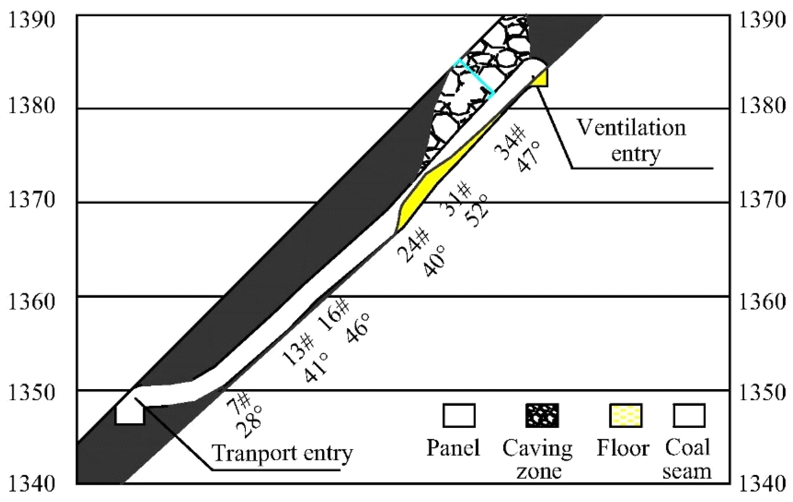
Current underground mining relies on three types of extracting methods for thick and steeply-inclined hard coal deposits. The first two methods are based on longwall top coal caving (LTCC) technology. When the deposit’s dip angle is up to 50°, LTCC is applied and adjusted to the longwalls that are parallel to stratification, but only in Chinese mines (Figure 1) [4,8,15,16].
The longwall height is usually about 2.5 m, and another 2–5 m of coal thickness is released from the roof. In this case, the fully mechanized longwall systems are additionally equipped with devices that stabilize the powered roof support and the longwall face conveyors. The mining of steeply inclined longwall faces is, however, associated with many problems mainly related to roof stability, as well as maneuvering with roof support, the conveyor, and the shearer. Work safety conditions require extensive worker experience and the use of advanced process solutions. For those reasons, mining of thick seams, whose inclination exceeds 40°, was abandoned in Poland.
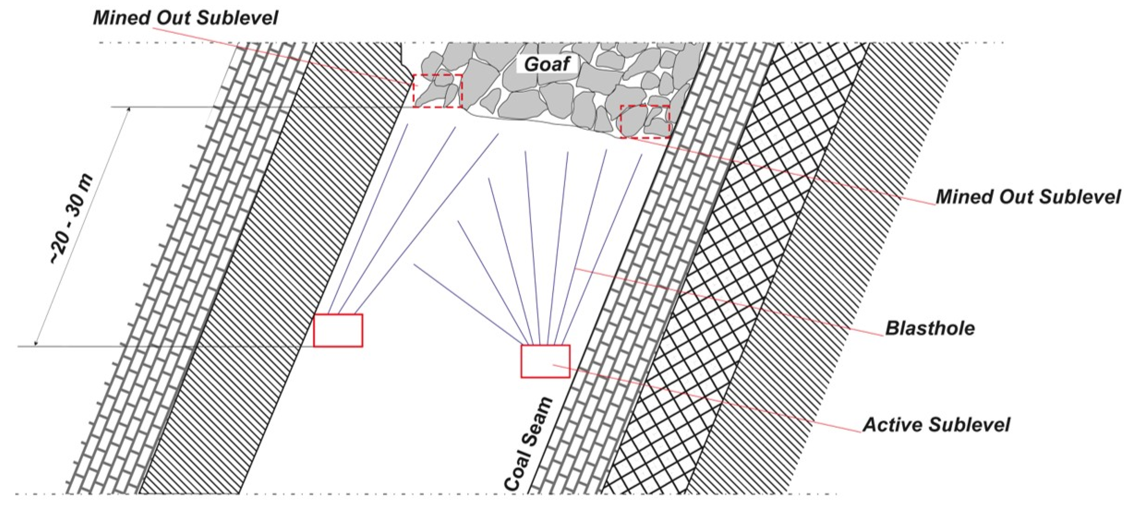
The second type of system requires coal seam subdivision into horizontal levels and mining of the particular level by subsequent longwall or shortwall top coal caving faces from top to bottom [17,18,19,20]. Levels of 2.5–3.5 m are mined with a shearer, followed by dropping the top coal whose thickness ranges from several to a dozen or so meters (Figure 2).
In this, typical mechanical systems are applied in the LTCC technology, which is why the method is fully mechanized. Such systems have been applied for several decades and several variations have been developed, e.g., the French sutirage or the Slovenian velenje [21,22,23,24,25,26]. The system has been used to extract steep coal seams 20–25 m thick in the Spanish province of Leon [27] using shortwall top coal caving. The shortwall fittings are a bit different there compared with typical solutions. The system uses a single-drum shearer and light sets of frame supports. Due to hardness of the coal, top coal dropping is preceded by layer destruction using blasting operations.
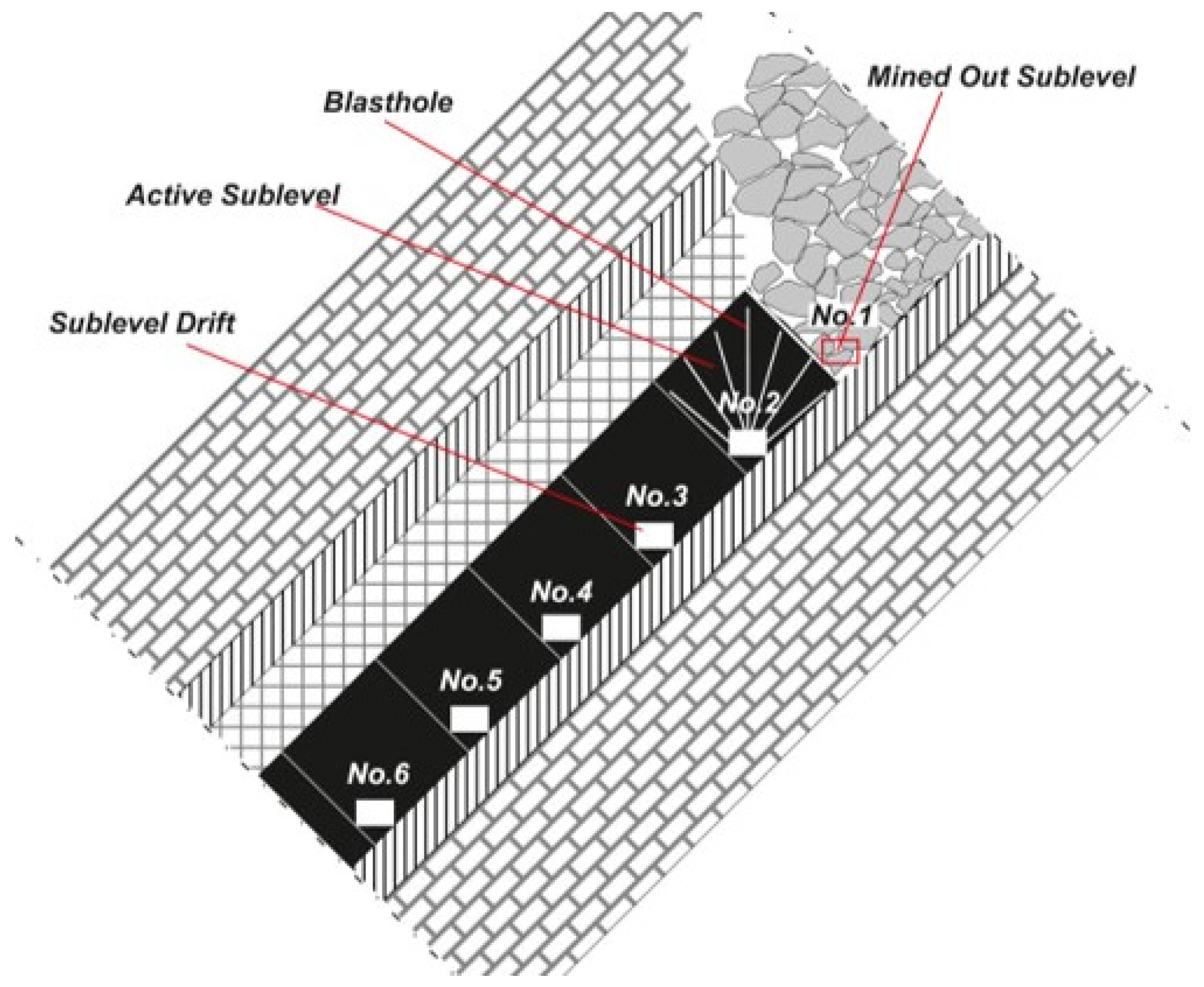
The third system is called sublevel caving, which was the focus of this study. The system is widely applied in underground ore mining [28,29]. Here, top coal is not dropped to the longwall or shortwall, but rather to the excavation system called the “sub-level drift”, which has a cross-section ranging from a dozen or so, to more than 20 m2. Depending on coal seam thickness, one to three sub-level drifts are performed on each sub-level. Extraction is performed by dropping the previously mined coal using fan-cut blasting pattern operations (Figure 3) [30,31,32,33]. Another method is based on hydro-cutting instead of blasting. Water is used in the cutting process for both coal cutting and transportation [34,35,36,37].
The sub-level height usually ranges from several meters to about 30 m. This system is characterized by low capital investments into mine-face equipment and low operating costs. Sub-level drifts are protected by steel supports that are dismantled before top coal dropping; thus, the supports can be reused many times. Coal loading is performed either only by gravity or by scop feeders, with transportation by chain and belt conveyors. Two to three miners are employed at the mine face. In this study, we constructed a detailed coal-seam mining method and described a mechanization system. However, much larger coal loss is another typical feature of the system in question. The coal loss usually does not exceed 15% in the LTCC systems, but can be more than 50% in the sub-level caving systems.
We introduced a unique face mechanization method in the Kazimierz-Juliusz coal mine in Poland to extract a bed about 20 m thick and inclined at more than 40°. The Kazimierz-Juliusz coal mine in Sosnowiec operated continually from 1884 to 2015. Starting in the 1990s, coal was extracted only from the thick Seam 510. That seam had been mined by the longwall system in areas where inclination did not exceed 30°, with division into layers with roof caving or backfill. The coal resources were almost completely extracted at the beginning of this century. Extraction of the remaining portion of Seam 510, with an inclination of 35° to 50°, was the object of designs and tests conducted jointly by the researchers of the AGH University of Science and Technology, Faculty of Mining and Geoengineering, in Kraków, and the engineers of the Kazimierz-Juliusz coal mine [32,38]. As a result, a completely mechanized variant of the sub-level caving system was designed and applied with success from 2003 until the coal mine closed down in 2015.
The first part of this paper presents the geological conditions of Seam 510 in the area of extraction conducted by the mechanized sub-level caving system, as well as the basic issues related to extraction technology. We present an example of a method for making coal resources available and the preparation of coal beds, followed by mining works mechanization and a short description of the extraction technology. The second part of this paper contains the extractable resource mining rates. In this regard, certain repeatable relationships were identified in that area during about a dozen of years of mining. Such relationships are illustrated on the basis of the results obtained in two typical deposit fields.
2. Material and Methods
2.1. Geological Characteristics of the Research Area
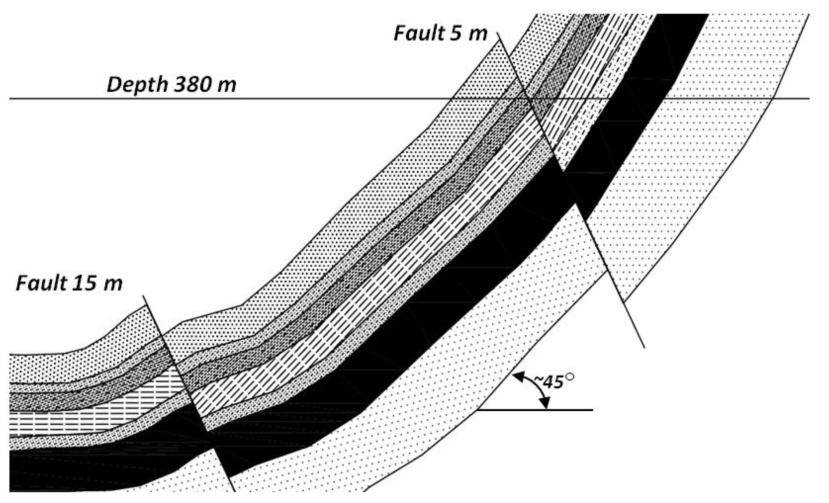
Seam 510 of mine section M-3 was deposited in the form of a trough. The trough bottom was about 500 m deep, with the deposit outcrop located at a depth of about 50 m in the trough wing. Mine section M-3 was cut through and divided into northern and southern parts by a fault dropping from 25 to 40 m. The coal seam inclination in the southern part, where the sub-level caving system was implemented, was 45° (Figure 4). The seam thickness varied in that area from 16 to more than 20 m. A number of faults were present in the mine section, representing various drop and direction parameters. Fault drops changed from several to about a dozen meters.
The average thermal coal properties of the mined coalbed are as follows: 3.5% ash, 0.4% sulphur, and 32.5% volatiles, with a calorific value of 5800 Kcal/kg and a density of 1.3 kg/m3. The coal of Seam 510 was characterized by an average uniaxial compressive strength (Rc) of more than 20 MPa, with the maximum value exceeding 35 MPa. The compressive strength of the sandstones occurring in the roof range from 30 to more than 70 MPa. The roof mudstone displayed strength ranging from 20 to more than 30 MPa, while the strength of sandy schist ranged from 30 to 40 MPa.
Seam 510 was classified as a Category I methane hazard (on a four-degree scale). However, the methane content of Seam 510 did not exceed 0.1 m3/Mgcsw (0.1 m3 of methane in one ton of dry and clean coal substance) in the area of the sub-level caving operation. The coal from Seam 510 across the whole coal mine was categorized as a Group V ignition temperature (on the five-degree scale of fire hazards), representing coal with a very high tendency to self-ignite. The self-ignition indicator of mine section M-3 coal was determined to be 179 °C/min, with an activation energy of 37 kJ/mol. The fire incubation time amounted to ca. 30 days.
The coal deposit level was categorized as a Degree II water hazard (on a three-degree scale). The aquifer located within the sandstone, lying above Seam 510, was the main source of water hazard. Coal workings and cutting operations caused water dripping and local leaks. Increased inflow was observed at the final stage of mining, with small influx from Tertiary sands.
Seam 510 was assigned to Degrees I and II of rock-burst hazard (on a three-degree scale). Coal mining by the sub-level caving method was performed in accordance with the regimes specific for Degree III rock-burst hazard due to the novelty of the mining method and the intention to ensure safety and obtain rock-mass data from the mining field. For that reason, the number of detectors (seismometers and geophones) was increased in the mining areas.
2.2. Sub-Level-Caving Mining Method—Assumptions and Practical Aspects
The high strength parameters of coal found at Seam 510 in the Kazimierz-Juliusz coal mine necessitated the use of blasting works for coal mining. Due to the changing coal seam thickness and its extent, the longwall or shortwall top caving methods were not used. Instead, a typical sub-level caving system with a single sub-level drift was applied in this coal seam.
2.2.1. General Description of the Sub-Level Caving System Applied in the Kazimierz-Juliusz Coal Mine
Mining panels were designed by dividing Seam 510 into horizontal blocks, determined by the planes perpendicular to the roof and bottom. The blocks, or mining panels, were shaped as cross-section squares with a vertically-situated diagonal. The square side length of the panel cross-section was close to the seam thickness in the given mining area, i.e., usually from 16 to 24 m [32,38]. The panel arrangement diagram for Seam 510 is shown in Figure 5.
One working, called the sub-level drift, was cut out from the transportation ramp in each mining panel at particular mine levels. These workings were cut out nearly horizontally, observing the direction of the seam extent at the seam’s bottom, starting with the lowest mining panel. The drift was cut out from the transportation ramp to the field boundary in the given deposit wing.
Once the sub-level drift reached the assumed mining panel boundary and after the drift was fitted, mining was conducted by caving. The mining operations continued by regularly repeated drilling of a fan-shaped blasting borehole arrangement, explosive charging and blasting, gravitational release, and coal removal with conveyors and reloading systems in the sub-level drift.
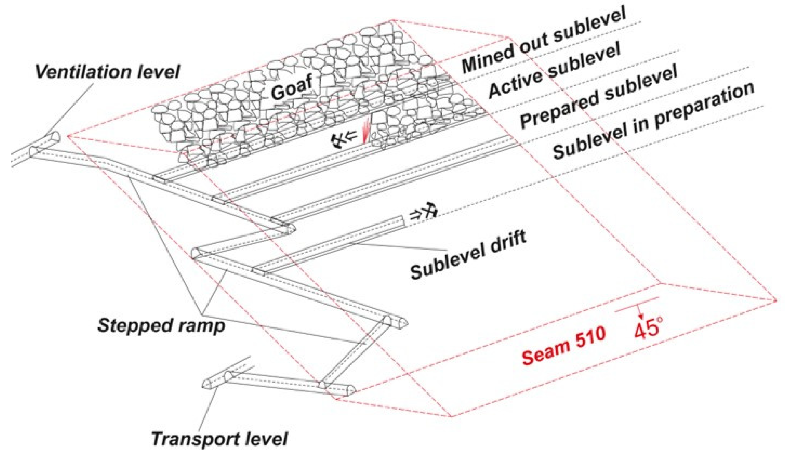
Mining was completed at the run out once the stopping line was reached, usually at the protection pillar location designed for the transport ramp. The face equipment was relocated to the subsequent panel before the final liquidation of the previous panel by placing an insulation plug. A diagram of the sub-level caving system applied in the Kazimierz-Juliusz coal mine is presented in Figure 6.
The details of the particular engineering stages of the sub-level caving mining technology applied for Seam 510 of the Kazimierz-Juliusz coal mine are provided in the sections below.
2.2.2. Development
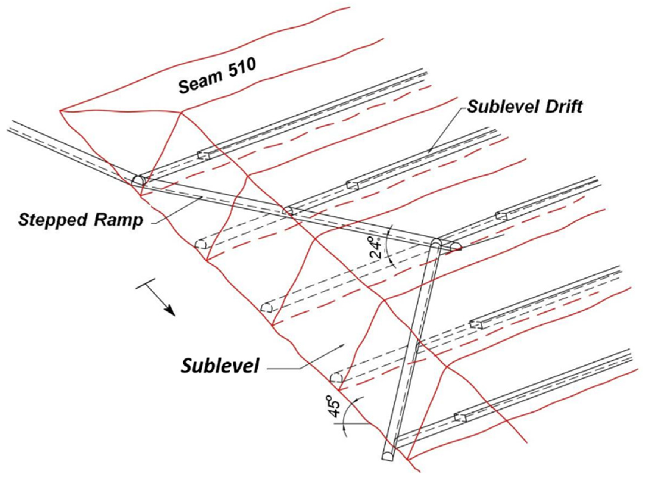
The connection of the mining and ventilation workings within the coal seam inclined at 45° (with a difference in height of ca. 110 and 170 m) was performed by cutting a series of stepped ramps. Such ramps were composed of fairly short sections (usually ca. 60 m each) situated diagonally with respect to the coal seam extent and with an inclination angle of 25° (Figure 7). This inclination of the stepped ramps allowed for cutting the workings with roadheader technology using typical mining equipment. Maintaining the 25° inclination allowed for deliveries of materials, including heavy support systems, chain conveyor components, and steel stands, as well as coal delivery by conveyors. The ramps were placed under arched supports composed of V25 sections.
Sub-level drifts constituted the last link in the preparatory working arrangement designed for the sub-level caving system. The workings were cut from stepped ramps with a slight elevation of up to 5° along the coal seam bottom in the places determined by the field subdivision into particular mining panels (Figure 5). The distances between the operating drifts depended on the coal seam thickness; they were usually similar to seam thickness but no shorter than ca. 15 m.
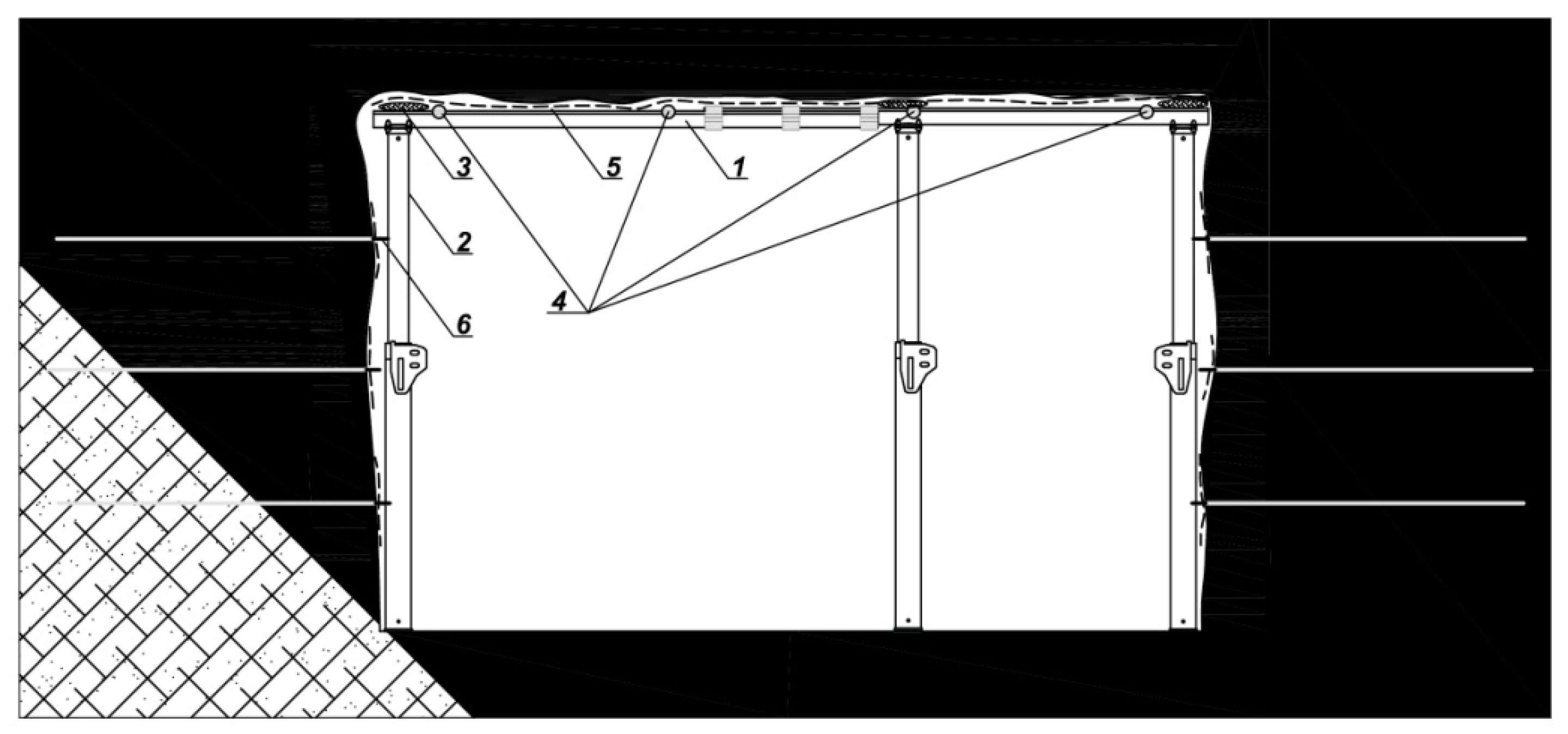
Similar to stepped ramp cutting, the sub-level drifts were cut out by the roadheader technology using typical transportation machines and equipment. The sub-level drifts were executed with rectangular supports in compliance with the shape of the powered support set used in the mining face at the mining works stage. A diagram of the rectangular sub-level drift support is presented in Figure 8.
2.2.3. Mining Face Equipment
The face of the sub-level drift was equipped with a system of three basic installations used for support, coal haulage, and borehole drilling as follows: powered roof support (PRS) powered roof support (BME Novaky, Novaky, Slovakia), Nowomag PZ-1000 chain conveyor (Famur, Katowice, Poland) and VPS-01 portable drilling machine (InterCupro, Ostrava, Czech Republic).
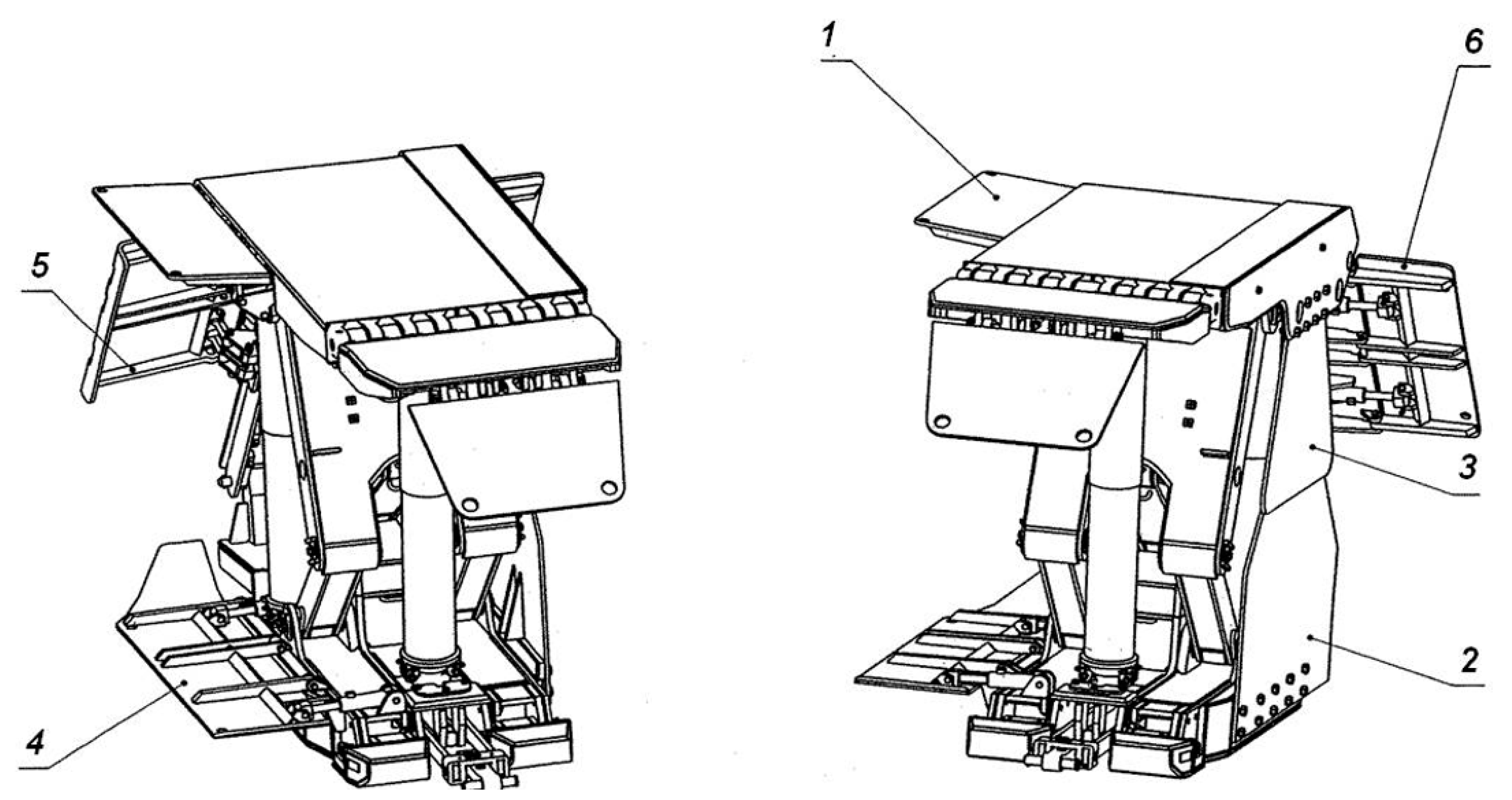
In addition, the mining faces were equipped with small tools such as pneumatic hammers, pneumatic or hydraulic screwdrivers, pneumatic blasters, burst charge and clay wad devices, and other blasting equipment. The protection of working areas at the face was provided by the PRS system. The set was composed of two specially-designed powered roof supports whose main task was to protect the area against dropping rocks or uncontrolled relocation of coal or waste rocks (Figure 9).
The PZ-1000 conveyor was used for the transport of coal released from the roof, i.e., by gravitational loading, directly after charge blasting. The conveyor structure allowed for retaining the conveyor crossover within the caving area ca. 5 m from the PRS protection system, facilitating transportation of coal released in the caving area.
The VPS-01 hydraulic drilling machine was installed at the mining face. That device was designed for drilling small-diameter blasting boreholes in coal and rock using the rotation method.
2.2.4. Coal Cutting Method
The mining technology based on the sub-level caving system design applied in the Kazimierz-Juliusz coal mine involved three separate stages: installation of face equipment, mining, and sub-level drift liquidation (backfill of drift end). The following sections of this paper only describe the mining proper, which consisted of a typical sub-level caving system application, with regularly repeated operations: drilling, explosive charging, and blasting, followed by gravitational release of coal, haulage, and relocation of the face equipment.
2.2.5. Blasting Works
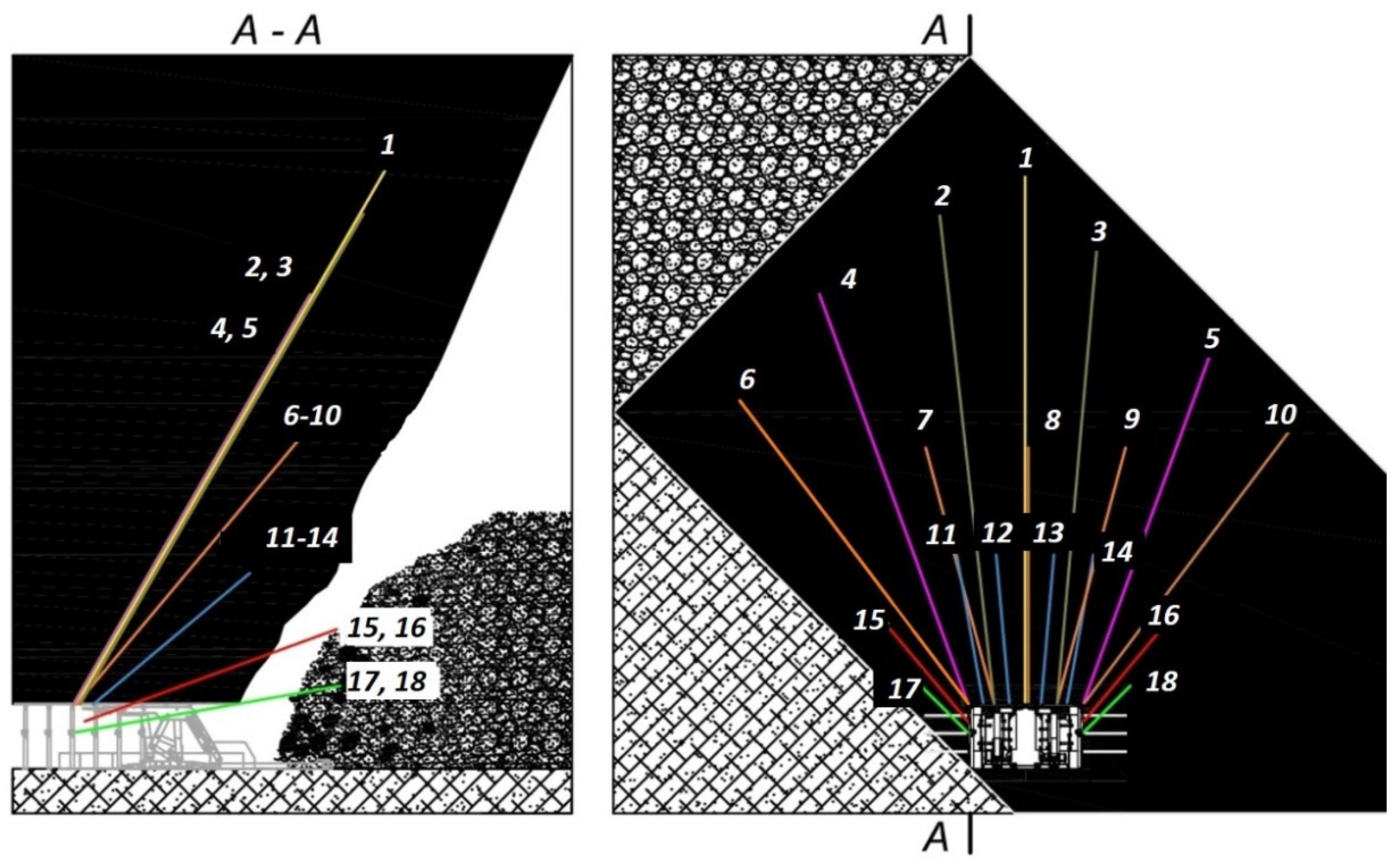
Each time when mining started in the sub-level drift, the start-up blasting works were conducted using a different procedure than the standard method applied during regular mining. After completion of the start-up blasting works (i.e., after full caving in the whole cross-section of the given mining panel), the coal seam was extracted upon borehole drilling, explosive charging, and blasting, in accordance with one of the blasting procedures designed for regular coal mining. Figure 12 presents a sample diagram of blasting borehole distribution. Blasting boreholes were drilled for mining purposes using one VPS-01 portable stand drilling machine. Usually, the boreholes for mining blasting had a diameter of 45 mm and the length of up to 30 m. Barbaryt 4HM explosive (Nitroerg, Bieruń, Poland) was mainly used in blasting works; it is a nitroglycerine-based material applied in coal deposit blasting in the presence of methane. The boreholes were plugged by clay wads packed in paper containers. Detonations were conducted with the use of the Nitrocord 8 pentrite detonation cord (Nitroerg, Bieruń, Poland) initiated by either Ergodet 0,.5AN instant or Ergodet 0o45A25M millisecond electric detonators (Nitroerg, Bieruń, Poland).
At the beginning, mining blasting was performed using traditional coal rock mass cutting methods, i.e., using up to 20 m long and up to 45 mm diameter blasting boreholes, with manual explosive charging and stemming. With time, however, pneumatic explosive charging was also applied in parallel, although the latter method required 75 mm diameter blasting boreholes, which allowed for shortening the charging process by half. A vinyl hose and a pneumatic blaster were used for pneumatic charging.
About 1 kg of the explosive material was pumped into a 1 m long and up to 45 mm diameter blasting borehole. For the 75 mm diameter boreholes, the quantity of the explosive material was about 5 kg per 1 m of borehole. With the progression of extraction, the results of cutting were analyzed and experience allowed for selection of a proper blasting procedure. In particular, the distribution, lengths, and diameters of boreholes, as well as charge sizes, were optimized. Both the number of boreholes in the fan arrangement and their distribution changed depending on the local conditions of the coal seam location (mainly its thickness, tectonics, and coal Rc). On average, 16–19 mining boreholes were drilled for one blasting operation. The boreholes were arranged in three fans, with each row of the fans inclined at a different angle, and the boreholes were of various lengths (Figure 12). Four undercutting boreholes were drilled within the drift walls (two on each side). According to Polish mining law, blast holes had to be fired simultaneously. The borehole length did not reach the full mining panel height, i.e., boreholes were not drilled and blasted directly under the coal seam roof or under the higher panel caving zone. A coal shelf about 2 m thick was left, which delayed the roof caving process. Although the process caused loss of a certain coal quantity, it reduced the loss in quality. When coal was still hanging after blasting and top coal release, additional boreholes were blasted. A unit charge (or the quantity of explosive in one borehole) weighed from 5 to 20 kg depending on the borehole length. During a single face blasting job (with the total charge blasted), 100 to nearly 300 kg of explosives were fired. The average consumption of the explosives amounted to ~0.29 kg per ton of coal.
2.2.6. Coal Release and Delivery
After blasting and drift face ventilation, the miners released the top coal. The process consisted of the transportation of the coal using a PZ-1000 conveyor whose crossover station was located within the release zone (Figure 13 and Figure 14).
The conveyor supplied the coal to subsequent chain and belt conveyors that were arranged in series in the sub-level drift and other workings toward the shaft. Released coal streaming was controlled by opening and closing of the internal protection against the caving of the PRS section (Figure 9).
The periods of coal release were diverse and usually continued for several dozens of minutes. During that process, the face miners properly opened the PRS internal protection against caving (Figure 9, Item 5) to control the feed to the conveyor and prevent jamming of the face zone under the PRS. The miners were also responsible for observation of the coal stream and stopping delivery when oversize coal boulders fell. Such boulders would be cut by pneumatic hammers or crushers mounted on the PZ-1000 conveyor. Occurrence of oversize coal boulders depended on the effectiveness of the blasting procedure applied. When blasting works were poor, the conveyor had to be stopped often, which caused reduced face yield and output.
The essential experience gain from coal release in the Kazimierz-Juliusz coal mine was the direct roof caving behind PRS, which was also associated with the extent of blasting works. The effect was visible in the void created after the release of cut coal. Roof caving delay also contributed to the very low losses in coal quality. The roof caving occurred periodically and the goaf often filled the whole excavation void behind the PRS. When that was the case, the continuation of coal extraction and release works were usually not justified because of quality losses. The losses were mainly caused by a considerable difference between the coal density (1.3 Mg/m3) and the roof rock density (2.5 Mg/m3), which was transported quickly in the released coal stream. In such cases, once a large roof caving was observed and rocks were found on the PZ-1000 conveyor, regular operation was stopped at the mining face. Instead of drilling boreholes, the face equipment was relocated by 3–5 m, followed by the replacement of the collected steel stands with wooden ones. Consequently, a small coal pillar was left, separating the face in the new position away from the roof caving site. That operation was followed by regular mining until another full roof caving. The necessity of using protection pillars increased with the progress of mining in the given mining field. Consequently, the deposit use indicator gradually reduced with the progress of extraction in the mining field. Coal left in the gob zone and pillars constituted the mining losses of extractable resources. Together with the progress of mining operations in the coal mine, such losses increased until the loss rate of 50% was achieved. The course of the extractable resource mining rate changes is described in the next section.
3. Results and Discussion—Extractable Resource Mining Rate
During about a dozen years of extraction of Seam 510, a repeatable changeability of the extractable resource mining rate changes was identified. Our priority was to maintain a low level of quality losses during coal extraction. The level of extracted coal contamination with gangue did not exceed about 3%, and maintaining the required regime was associated with the generation of quality losses. As mentioned in Section 2.2.6, the appearance of a continuous gangue stream on a conveyor ended each time with immediate interruption of coal release. When large-volume gangue appearing in the gob zone created a stream, it prevented further coal release. Our observations were confirmed by model testing [39]. The continuous mining procedure would cause losses of coal remaining in the gob zone (unreleased coal) and losses of coal remaining in the pillar (3–5 m thick). On each lower sub-level drift, extraction losses increased, affecting the extractable resource mining rate. Simultaneously, typical models of rate changes were observed. That phenomenon presented in two mining fields: Fields A and B. These two fields were selected due to the regularity of seam locations within their areas and, primarily, the lack of significant faults at the end of sub-level drifts that would have obviously distorted the results of observations of the extractable resource mining rate changes. The seam inclination was constant in both fields (ca. 45°), with the seam thickness ranging from 16 to 24 m. The mining panel length (or sub-level drift length) generally did not exceed 200 m in the two fields. The mining depth ranges from 280 to 550 m. Table 1 and Table 2 describe the particular sub-level drifts in both fields together with their extractable resources, extracted resources, and percentage rates of extractable resource mining. The sub-level drifts are arranged in the tables in accordance with the mining sequence or from the shallowest to the deepest drifts.
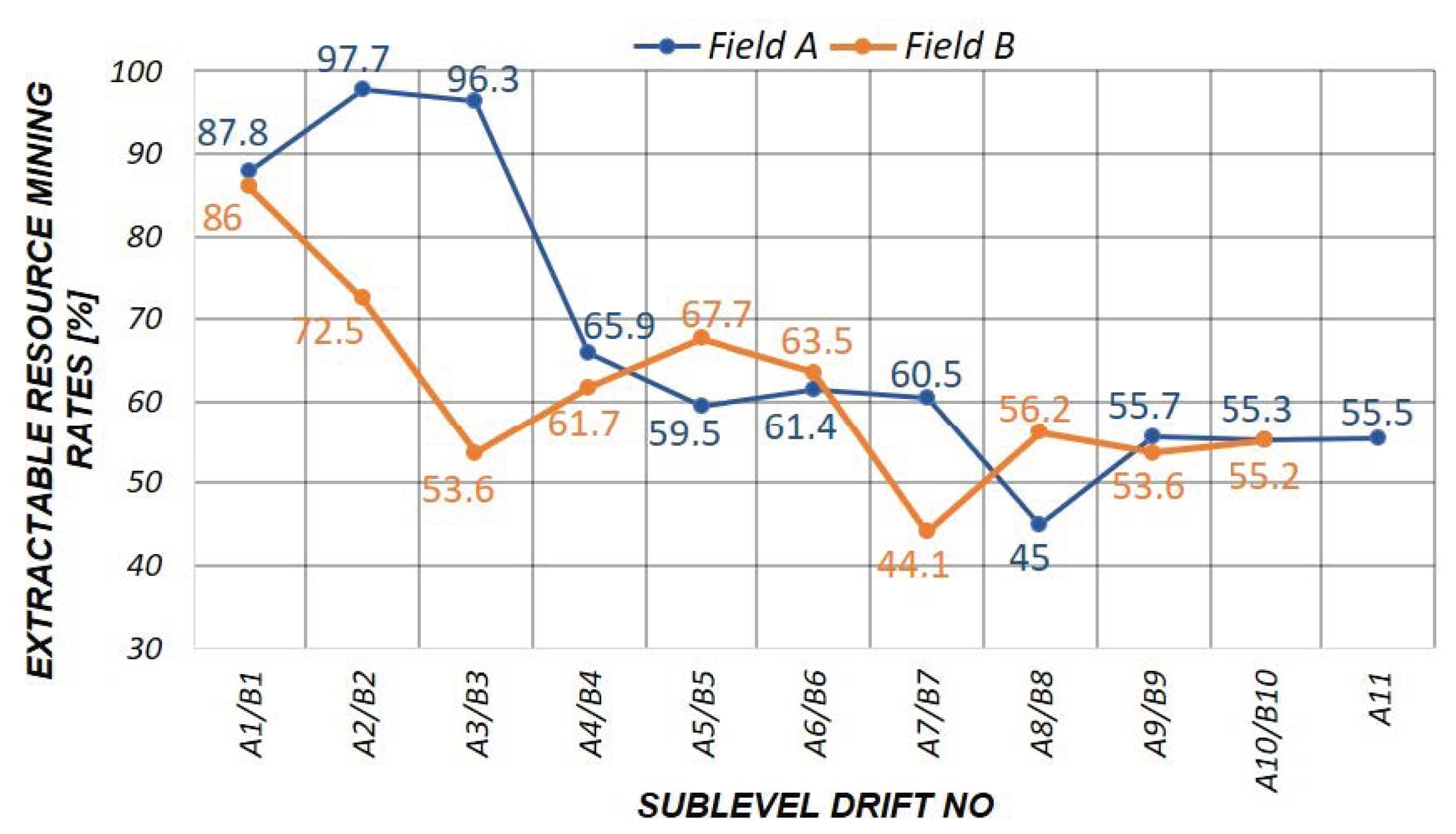
Figure 15 presents the extractable resource mining rate changes in both fields. Our analysis considered 11 subsequent mining panels (or sub-level drifts) in Field A and 10 in Field B. The exploitable resources were recognized in particular fields, at both the sub-level drifts cutting and mining operations stages. The seam thickness was determined by the drilling method.
Consequently, a high accuracy of resource recognition was attained. In both cases, at the initial stage of field mining (in the first sub-level drifts), the extractable resource mining rate exceeded 80% (and even 90% in Field A).
In the fourth sub-level drift of Field A and the third in Field B, we observed a considerable increase in resource losses. The rate dropped to ca. 66% and 54%, respectively. Later, rate stability was observed at the level of more than 60% in both sub-level drifts. This was followed by a sudden drop in the rate (below 45%) in both mining fields and, again, rate stability at a level exceeding 50%. The average extractable resource mining rates of those fields were 67.3% and 61.4%, respectively.
A rate drop from 80–90% to the final stable level exceeding 50% was also observed in other mining fields. Due to the seam distortions in the form of faults and local seam thickness reductions, other local distortions appeared within the trends presented above, generally in the form of local drops in the extractable resource mining rates. The observed course of the extractable resource mining rate changeability may be associated with the effects of rock pressure. Upon extraction of each subsequent mining panel, pressure on the undercut roof layers increased, followed by roof cracking and the appearance of caving. The roof cracking intervals depended on the roof-rock strength parameters, the span of the undercut roof, and the depth of the specific mining panel. Sub-level drift roof cracks migrated toward the coal release area at the drift face, producing gangue streams on the conveyors in cycles depending on the respective roof-rock strength parameters. Based on the experiences collected in the Kazimierz-Juliusz coal mine, building a precise and general model of extractable resource losses under the sub-level caving system would be difficult. However, we can assume that, in terms of quality, the process will occur similarly to that identified in deposits of similar structure. The relevant observations presented here should be useful in the production planning process and or prediction of the extractable resource mining rates when using the sub-level caving system in the extraction of thick and steeply inclined deposits.
4. Conclusions
The sub-level caving extraction system presented here constitutes a unique face mining mechanization solution for extraction from thick and steeply inclined coal seams. In our opinion, the system presented here should realistically allow for maintenance of the extractable resource mining rate of 50–95%, depending on geological conditions. When designing mining operations, the increase in mining losses to the level of even 50% should be considered, remembering that the final rate will mainly depend on the roof-rock strength parameters and the mining depth.
The application of the proposed mining system conception allowed for extraction of more than 12 million tons of coal from Seam 510 in 2003–2015. The effective solutions regarding the face protection systems, with maximum possible work mechanization, resulted in no serious accidents being recorded in the mining areas. Although the coal from Seam 510 was classified as belonging to self-ignition Group V, which is the highest in Poland, with a fire incubation time of about 30 days, no fire outbreaks occurred. The coal resources remaining in gobs did not present any hazard due to the relatively fast progress of face advance. In addition, the sub-level drift was ventilated by forced ventilation ducting. This system blocked the air flow through the gobs and coal within because, otherwise, breeding fire would be initiated. The ventilation performance was limited to the value of ca. 400 m3/min. Plugging and sealing the entrances to the abandoned sub-levels was the other equally essential factor that reduced the combustion hazard. A stopping system composed of mineral and cement binders was applied. Consequently, no drafts occurred from active sub-levels to goafs. Despite the low output, the coal mine obtained positive financial results each year due to the extraction of high-quality coal from Seam 510 with relatively low operating costs and expenditures on drift-face protection systems. In the initial mining period, the mine-face costs (i.e., the operating costs borne in a single sub-level drift), including labor, materials, and electricity, were USD 11.8 per ton and the costs regularly decreased. In the third year of mining, the costs were about USD 7.2 per ton and that level was maintained until the end of the coal mine’s operation. The capital investment associated with the infrastructure in a single mine face, considering all the machines and equipment described in Section 2.2.3, was about USD 520,000.
The mining method discussed here was subjected to regular modifications regarding machine, equipment, and blasting operation designs during the first several years of mining. Gradual improvements allowed the engineers to obtain a high level of system efficiency, except for one component. Blast hole drilling was the weakest process, and it was never improved. The mine face was equipped with only one VPS-01 portable drilling machine, which is why the drilling works required a whole shift. Fitting the mine face with a mobile two-arm drilling machine, suspended on the steel support of the sub-level drift, would considerably improve work efficiency. Even better results could be obtained by the implementation of two independent compact crawler drilling machines. Such machines could operate in parallel on two sides of the Nowomag PZ-1000 chain conveyor. In this case, it would be necessary to increase the sub-level drift width from 4.5 to 5.5 m, which would slightly increase the costs of preparatory works. The system has developmental potential. We therefore hope to both improve system efficiency and reduce mining costs with respect to the values that were attained in the Kazimierz-Juliusz coal mine.
Author Contributions
Conceptualization, Z.R., J.S., Z.B. and D.C.; methodology, Z.R., J.S., Z.B. and D.C.; validation, J.S. and D.C.; formal analysis, Z.R. and Z.B.; investigation, Z.R., J.S., Z.B. and D.C.; resources, Z.R., J.S., Z.B. and D.C.; writing—original draft preparation, Z.R., J.S., Z.B. and D.C.; writing—review and editing, Z.B. and D.C.; visualization, Z.R. and J.S.; supervision, Z.R. and Z.B. All authors have read and agreed to the published version of the manuscript.
Funding
The article was funded by AGH University of Science and Technology, Faculty of Mining and Geoengineering; subsidy number: 16.16.100.215.
Conflicts of Interest
The authors declare no conflict of interest.
References
- Wu, Y.; Liu, K.; Yun, D.; Xie, P.; Wang, H. Research progress on the safe and efficient mining technology of steeply dipping seam. J. China Coal Soc. 2014, 39, 359–364. [Google Scholar]
- Deng, Y.; Wang, S. Feasibility analysis of gob-side entry retaining on a working face in a steep coal seam. Int. J. Min. Sci. Technol. 2014, 24, 499–503. [Google Scholar] [CrossRef]
- Shi, P. The complexity of basic roof’s breaking movement in highly inclined seam. Mine Press Roof Manag. 1999, Z1, 26–28. [Google Scholar]
- Xiaomeng, L.; Zhaohui, W.; Jinwang, Z. Stability of roof structure and its control in steeply inclined coal seams. Int. J. Min. Sci. Technol. 2017, 27, 359–364. [Google Scholar]
- Zhang, Y.; Zhang, B.; Li, L. Study on the effect of roof fracture development on gas drainage in steep full-mechanized caving mining. J. Min. Saf. Eng. 2014, 31, 809–813. [Google Scholar]
- Xie, P.; Wu, Y.; Wang, H. Study on space activity law of overburden strata above longwall coal mining face in high inclined seam. Coal Sci. Technol. 2012, 40, 1–5. [Google Scholar]
- Liu, C.; Yang, J.; Wu, F. A proposed method of coal pillar design, goaf filling, and grouting of steeply inclined coal seams under water-filled strata. Mine Water Environ. 2015, 34, 87–94. [Google Scholar] [CrossRef]
- Wang, J.; Wei, W.; Zhang, J. Theoretical description of drawing body shape in an inclined seam with longwall top coal caving mining. Int. J. Coal Sci. Technol. 2019, 7, 82–195. [Google Scholar] [CrossRef] [Green Version]
- Zhang, Z.; Liu, X.; Meng, T. Analysis and evaluation on stability of the steep coal seam gob. Adv. Civ. Ind. Eng. 2013, 353, 1502–1506. [Google Scholar] [CrossRef]
- Yang, W.; Li, L.; Li, X.; Wang, L. Water outbursts in underground mining with steeply dipping coal seams: Numerical simulations based on a mining case. Eur. J. Environ. Civ. Eng. 2014, 18, 511–535. [Google Scholar] [CrossRef]
- Dong, L.; Tong, X.; Li, X.; Zhou, J.; Wang, S.; Liu, B. Some Developments and New Insights of Environmental Problems and Deep Mining Strategy for Cleaner Production in Mines. J. Clean. Prod. 2019, 210, 1562–1578. [Google Scholar] [CrossRef]
- Dong, L.; Sun, D.; Shu, W.; Li, X. Exploration: Safe and Clean Mining on Earth and Asteroids. J. Clean. Prod. 2020, 257, 120899. [Google Scholar] [CrossRef]
- Tu, H.; Tu, S.; Zhang, C.; Zhang, L.; Zhang, X. Characteristics of the Roof Behaviors and Mine Pressure Manifestations During the Mining of Steep Coal Seam. Arch. Min. Sci. 2017, 62, 871–891. [Google Scholar]
- Zhao, T.; Zhang, Z.; Yin, Y.; Tan, Y.; Liu, X. Ground Control in mining steeply dipping coal seams by backfilling with waste rock. J. S. Afr. Inst. Min. Metal. 2018, 118, 15–26. [Google Scholar] [CrossRef]
- Yajun, X.; Panfenga, G.; Fudong, G. Analysis of stability of support and surrounding rock in mining top coal of inclined coal seam. Int. J. Min. Sci. Technol. 2014, 24, 63–68. [Google Scholar]
- Xie, P.; Wu, Y.; Wang, H.; Ren, S. Interaction characteristics between strata movement and support system around large mining height fully-mechanized face in steeply inclined seam. J. Min. Saf. Eng. 2015, 32, 14–19. [Google Scholar]
- Tu, H.; Tu, S.; Yuan, Y.; Wang, F.; Bai, Q. Present situation of fully mechanized mining technology for steeply inclined coal seams in China. Arab. J. Geosci. 2015, 8, 4485–4494. [Google Scholar] [CrossRef]
- Cao, S.; Zhang, Z.; Peng, Y.; Liu, H. Technology of fully mechanized strike longwall mining in steep inclined seam. Coal Sci. Tech. 2010, 38, 23–26. [Google Scholar]
- Xingping, L.; Pengfei, S.; Jiantao, C.; Huan, S.; Zhengyong, S.; Feng, C. Hybrid assessment of pre-blasting weakening to horizontal section top coal caving (HSTCC) in steep and thick seams. Int. J. Min. Sci. Technol. 2014, 24, 31–37. [Google Scholar]
- Wang, Z.; Dou, L.; Wang, G. Coal Burst Induced by Horizontal Section Mining of a Steeply Inclined, Extra-Thich Coal Seam and Prevention: A Case Study from Yaojien No. 3 Coal Mine, China. Hindawi. Shock Vib. 2019, 2019. [Google Scholar] [CrossRef]
- Coates, D.F. Three Mining Methods for Vertical, Inclined and Thick Coal Seams Used in France. CIM Trans. 1972, 85, 96–102. [Google Scholar]
- Schneiderman, S.J. Mining Thick and Irregular Seams in France; World Coal: London, UK, 1980; Volume 6, pp. 30–34. [Google Scholar]
- Benech, M.; Collod, H. Soutirage Mining Used Effectively for Thick and Irregular Coal Seams; World Coal: London, UK, 1982; Volume 8, pp. 51–54. [Google Scholar]
- Ahcan, R. Mechanization and Concentration of Thic Coal Seams Mining in SSFR Yugoslavia. In Proceedings of the International Symposium on Thick Seam Mining, London, UK, 18–21 May 1980; Volume 4, pp. 1–5. [Google Scholar]
- Jeromel, G.; Medved, M.; Likar, J. An analysis of the geomechanical processes in coal mining using the velenje mining method. Acta Geotech. Slov. 2010, 7, 31–45. [Google Scholar]
- Likar, J.; Medved, M.; Lenart, M.; Mayer, J.; Malenkovi´c, V.; Jeromel, G.; Dervariˇc, E. Analysis of geomechanical changes in hanging wall caused by longwall multi top caving in coal mining. J. Min. Sci. 2012, 48, 135–145. [Google Scholar] [CrossRef]
- Toraño, J.; Torno, S.; Alvarez, E.; Riesgo, P. Application of outburst risk indices in the underground coal mines by sublevel caving. Int. J. Rock Mech. Min. Sci. 2012, 50, 94–101. [Google Scholar] [CrossRef]
- Hustrulid, W.; Kvapil, R. Sublevel caving—Past and future. In Proceedings of the 5th International Conference and Exhibition on Mass Mining, Luleå, Sweden, 9–11 June 2008; Luleå University Press: Luleå, Sweden, 2018; pp. 107–132. [Google Scholar]
- Brunton, I.D.; Fraser, S.J.; Hodgkinson, J.H.; Stewart, P.C. Parameters influencing full scale sublevel caving Material recovery at the Ridgeway gold mine. Int. J. Rock Mech. Min. Sci. 2014, 47, 647–656. [Google Scholar] [CrossRef]
- Bise, C.J.; Ramani, R.V.; Stefanko, R. Underground Extraction Techniques for Thick Coal Seams; The American Institute of Mining: New York, NY, USA, 1977; pp. 35–40. [Google Scholar]
- Dokukin, A.V. Research in the Coal Industry of the U.S.S.R.; World Coal: London, UK, 1977; pp. 65–68. [Google Scholar]
- Rak, Z. Mechanised sublevel caving systems for winning thick and steep hard coal beds. In International Mining Forum 2010: Mine Safety and Efficient Exploitation Facing Challenges of the 21 Century; CRC Press: Boca Raton, FL, USA, 2010; pp. 361–370. [Google Scholar]
- Jeremic, M. Strata Mechanics in Coal Mining; A.A. Balkema: Rotterdam, The Netherlands; Boston, MA, USA, 1985. [Google Scholar]
- Otsuka, T. Hydraulic Mining at Sunagawa Coal Mine. In Proceedings of the 4th Joint Meeting MMIJ-AIME, Tokyo, Japan, 4 November 1980; pp. 63–75. [Google Scholar]
- Mills, L.J. Hydraulic Mining in the U.S.S.R. Min. Eng. 1978, 6, 655–663. [Google Scholar]
- Jeremic, M.L. Hydraulic Mining Possible Method for Rocky Montain. Coal Min. Mag. 1979, 141, 330–338. [Google Scholar]
- Parkes, D.M.; Grimley, W.T. Hydraulic Mining Coal. Min. Congr. J. 1975, 61, 26–29. [Google Scholar]
- Rak, Z.; Stasica, J.; Burtan, Z. Ocena możliwości wykorzystania krótkofrontowych i specjalnych systemów eksploatacji w kopalniach węgla kamiennego w Polsce—The assessment of the possibility to use short-front and special mining systems in the coal mines in Poland. Bezpieczeństwo Pr. I Ochr. Środowiska W Górnictwie 2011, 11, 9–17. [Google Scholar]
- Klishin, S.V.; Klishin, V.I.; Opruk, G.Y. Modeling Coal Discharge in Mechanized Steep and Thick Coal Mining. J. Min. Sci. 2013, 49, 932–940. [Google Scholar] [CrossRef]
Figure 1.
Diagram of an inclined wall mined by the longwall top coal caving (LTCC) system in the Dayuan Coal Mine [4].
Figure 1.
Diagram of an inclined wall mined by the longwall top coal caving (LTCC) system in the Dayuan Coal Mine [4].

Figure 2.
Shortwall top coal caving method with the coal seam subdivided into horizontal levels.

Figure 3.
Sub-level caving in a coal seam, with two drifts [33].
Figure 3.
Sub-level caving in a coal seam, with two drifts [33].

Figure 4.
Cross-section of Seam 510 in mine section M-3 of the Kazimierz-Juliusz coal mine.

Figure 5.
Subdivision of Seam 510 into mining panels with extraction sequence [32].
Figure 5.
Subdivision of Seam 510 into mining panels with extraction sequence [32].

Figure 6.
Sub-level caving system diagram.

Figure 7.
Stepped ramp diagram.

Figure 8.
Rectangular steel support of the sub-level drift. 1—steel roof bar made of two V25 sections, 2—valent steel friction stand, 3—welded steel mesh strut, 4—double acting steel brace, 5—timber lining, and 6—steel anchor with a steel mesh strut.
Figure 8.
Rectangular steel support of the sub-level drift. 1—steel roof bar made of two V25 sections, 2—valent steel friction stand, 3—welded steel mesh strut, 4—double acting steel brace, 5—timber lining, and 6—steel anchor with a steel mesh strut.

Figure 9.
Internal and external sides of a powered roof support (PRS). 1—internal cover of the canopy, 2—external cover of the base, 3—external cover of the canopy, 4—internal cover of the base, 5—internal protection against caving, and 6—external protection against caving.
Figure 9.
Internal and external sides of a powered roof support (PRS). 1—internal cover of the canopy, 2—external cover of the base, 3—external cover of the canopy, 4—internal cover of the base, 5—internal protection against caving, and 6—external protection against caving.

Figure 10.
Locations of the PRS and PZ-1000 in the mining face.

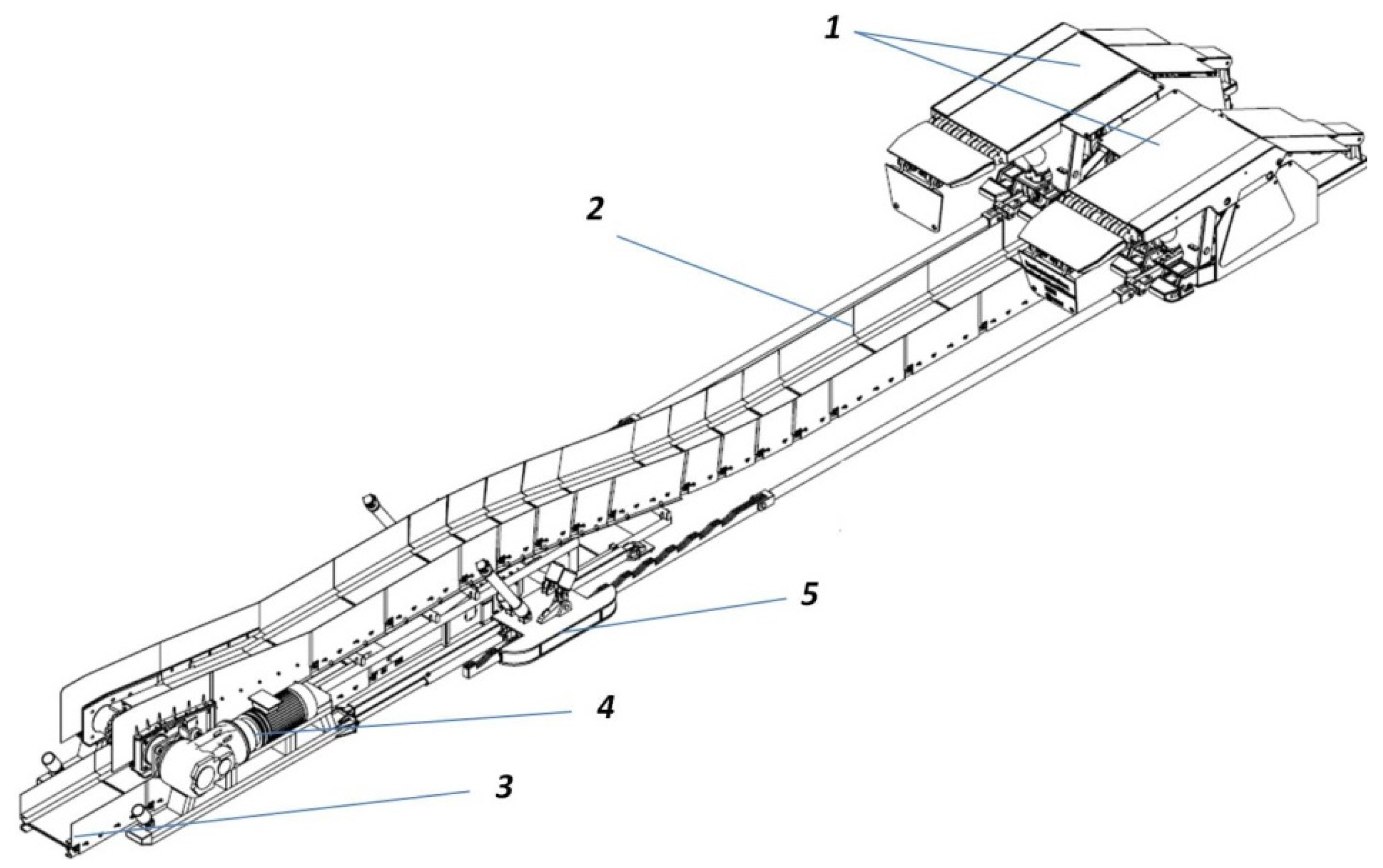
Figure 11.
PZ-1000 conveyor, with a sliding station and PRS. 1—PRS, 2—PZ-1000 conveyor, 3—another chain conveyor, 4—PZ-1000 drive, 5—sliding equipment.
Figure 11.
PZ-1000 conveyor, with a sliding station and PRS. 1—PRS, 2—PZ-1000 conveyor, 3—another chain conveyor, 4—PZ-1000 drive, 5—sliding equipment.

Figure 12.
Sample distribution of mining blasting works at the mining face.

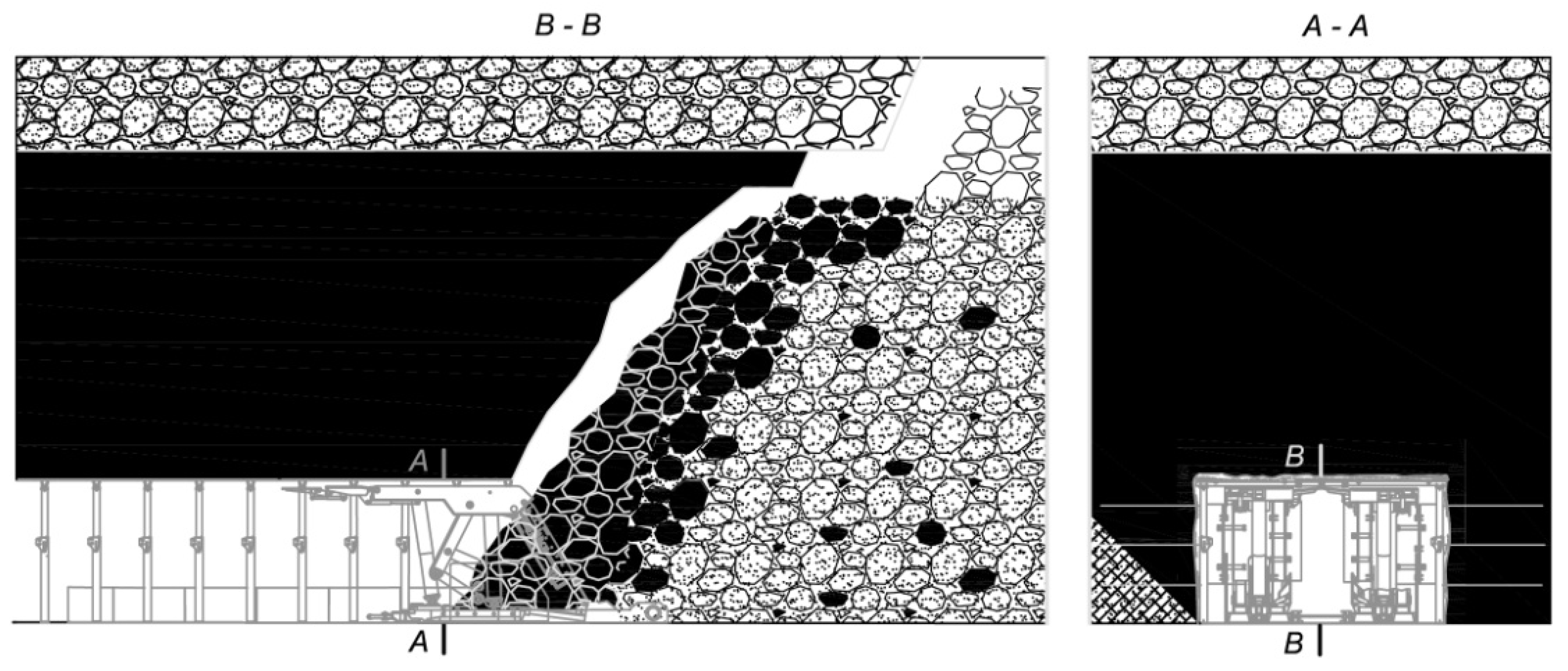
Figure 13.
Coal release diagram [10].
Figure 13.
Coal release diagram [10].

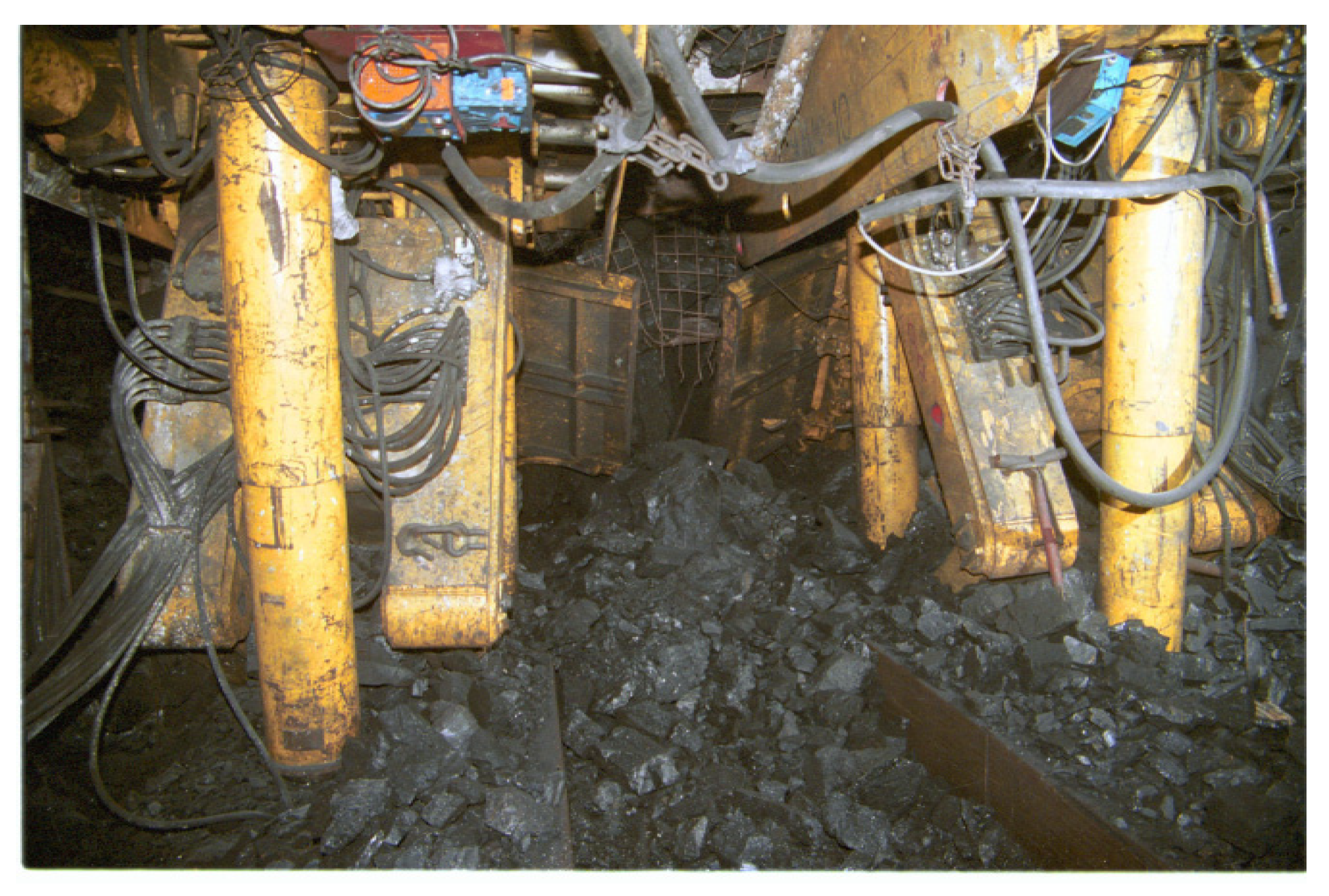
Figure 14.
View of the face when coal was released [10].
Figure 14.
View of the face when coal was released [10].

Figure 15.
The course of extractable resource mining rate changes in Fields A and B.


Table 1.
Extractable resource mining rates in Field A.
| Sub-level Drift No. | Sub-Level Drift Length (m) | Extractable Resources (Mg) | Output (Mg) | Extractable Resource Mining Rates (%) |
|---|---|---|---|---|
| A/1 | 82 | 27,211 | 23,891 | 87.8 |
| A/2 | 84 | 27,848 | 27,208 | 97.7 |
| A/3 | 120 | 45,738 | 44,063 | 96.3 |
| A/4 | 134 | 41,459 | 27,309 | 65.9 |
| A/5 | 136 | 54,264 | 32,261 | 59.5 |
| A/6 | 170 | 66,640 | 40,921 | 61.4 |
| A/7 | 172 | 75,852 | 45,921 | 60.5 |
| A/8 | 186 | 84,369 | 37,974 | 45 |
| A/9 | 142 | 60,832 | 33,908 | 55.7 |
| A/10 | 161 | 71,520 | 39,550 | 55.3 |
| A/11 | 174 | 69,950 | 38,850 | 55.5 |
| Σ Field A | 1561 | 625,683 | 391,856 | av. 67.3 |
Table 2.
Extractable resource mining rates in Field B.
| Sub-Level Drift No. | Sub-Level Drift Length (m) | Extractable Resources (Mg) | Output (Mg) | Extractable Resource Mining Rate (%) |
|---|---|---|---|---|
| B/1 | 107 | 31,158 | 26,794 | 86 |
| B/2 | 142 | 41,350 | 29,977 | 72.5 |
| B/3 | 155 | 58,590 | 31,389 | 53.6 |
| B/4 | 169 | 67,431 | 41,594 | 61.7 |
| B/5 | 191 | 74,872 | 50,712 | 67.7 |
| B/6 | 200 | 84,000 | 53,337 | 63.5 |
| B/7 | 178 | 65,789 | 29,031 | 44.1 |
| B/8 | 179 | 67,662 | 38,030 | 56.2 |
| B/9 | 185 | 66,245 | 35,520 | 53.6 |
| B/10 | 187 | 69,881 | 38,554 | 55.2 |
| Σ Field B | 1693 | 626,978 | 374,938 | av. 61.4 |
Publisher’s Note: MDPI stays neutral with regard to jurisdictional claims in published maps and institutional affiliations. |
© 2020 by the authors. Licensee MDPI, Basel, Switzerland. This article is an open access article distributed under the terms and conditions of the Creative Commons Attribution (CC BY) license (http://creativecommons.org/licenses/by/4.0/).
Share and Cite
MDPI and ACS Style
Rak, Z.; Stasica, J.; Burtan, Z.; Chlebowski, D. Technical Aspects of Mining Rate Improvement in Steeply Inclined Coal Seams: A Case Study. Resources 2020, 9, 138. https://0-doi-org.brum.beds.ac.uk/10.3390/resources9120138
AMA Style
Rak Z, Stasica J, Burtan Z, Chlebowski D. Technical Aspects of Mining Rate Improvement in Steeply Inclined Coal Seams: A Case Study. Resources. 2020; 9(12):138. https://0-doi-org.brum.beds.ac.uk/10.3390/resources9120138
Chicago/Turabian StyleRak, Zbigniew, Jerzy Stasica, Zbigniew Burtan, and Dariusz Chlebowski. 2020. "Technical Aspects of Mining Rate Improvement in Steeply Inclined Coal Seams: A Case Study" Resources 9, no. 12: 138. https://0-doi-org.brum.beds.ac.uk/10.3390/resources9120138
Note that from the first issue of 2016, this journal uses article numbers instead of page numbers. See further details here.