
The Wearable Robotic Forearm: Design and Predictive Control of a Collaborative Supernumerary Robot


Sibley School of Mechanical and Aerospace Engineering, Cornell University, Ithaca, NY 14850, USA
*
Author to whom correspondence should be addressed.
†
Current affiliation: Tata Consultancy Services, Bengaluru 560066, India.
Robotics 2021, 10(3), 91; https://0-doi-org.brum.beds.ac.uk/10.3390/robotics10030091
Submission received: 13 June 2021
/
Revised: 12 July 2021
/
Accepted: 13 July 2021
/
Published: 16 July 2021
Abstract
:This article presents the design process of a supernumerary wearable robotic forearm (WRF), along with methods for stabilizing the robot’s end-effector using human motion prediction. The device acts as a lightweight “third arm” for the user, extending their reach during handovers and manipulation in close-range collaborative activities. It was developed iteratively, following a user-centered design process that included an online survey, contextual inquiry, and an in-person usability study. Simulations show that the WRF significantly enhances a wearer’s reachable workspace volume, while remaining within biomechanical ergonomic load limits during typical usage scenarios. While operating the device in such scenarios, the user introduces disturbances in its pose due to their body movements. We present two methods to overcome these disturbances: autoregressive (AR) time series and a recurrent neural network (RNN). These models were used for forecasting the wearer’s body movements to compensate for disturbances, with prediction horizons determined through linear system identification. The models were trained offline on a subset of the KIT Human Motion Database, and tested in five usage scenarios to keep the 3D pose of the WRF’s end-effector static. The addition of the predictive models reduced the end-effector position errors by up to 26% compared to direct feedback control.
1. Introduction
Wearable robotic devices can augment the abilities of the human body beyond its natural limits, allowing users to extend their reach, lift more weight, and reduce physical and cognitive loads in repetitive tasks. The research on wearable robotics is mostly focused on prostheses and exoskeletons, reaching considerable maturity over the past years [1]. Prostheses serve as replacements for lost human functionality, while exoskeletons adhere to existing human limbs, either for support and rehabilitation of unhealthy joints, or for enhancing healthy limbs in tasks such as walking and lifting loads.
Expanding the scope of robotic augmentation, researchers have proposed supernumerary robotic (SR) devices for able-bodied persons, which add to human capabilities instead of replacing or supporting existing ones. The wearable robotic forearm (WRF) described in this article is aimed at assisting users in close-range collaborative tasks, while remaining lightweight and maneuverable. Building upon previous conference publications regarding its design process [2] and biomechanics [3], we provide additional descriptions of the robot’s mechanical architecture, kinematics, and control systems. We also extend upon preliminary work for 2D stabilization of the WRF’s end-effector previously published in conference proceedings [4], applying more robust predictive models to 3D stabilization scenarios involving a larger range of human motion.
One common configuration of SR devices seen in the literature is of large human-scale arms mounted on the user’s upper body, for instance a torso-mounted pair of robotic limbs for bracing and support of a crouching worker in settings such as aircraft manufacturing [5]. A second common configuration is wrist-mounted robotic fingers, designed to perform two-handed tasks with a single hand [6,7]. Wrist-mounted and torso-mounted configurations represent two extremes in terms of application, mounting point, size, weight, and power. The torso-mounted SR arms weigh over 15 kg and are capable of 50–70 Nm of torque, while the additional fingers typically weigh under 0.5 kg, with torques of up to 2 Nm. The WRF lies in between this spectrum of weight, power, and scale. Its latest prototype weighs about 2 kg with peak torques of 6 Nm, and is aimed at tasks with lower demands than the torso-mounted robots, leading to a smaller footprint. At the same time, its mounting configuration on the upper-arm allows for extended reach and multi-location work capabilities, in contrast to wrist-worn robots.
Aside from this form-factor, we envision the WRF to be an autonomous assistive agent, able to react and mutually adapt to the user through non-verbal communication based on body movements. This is in contrast to the prevailing paradigm in SR devices of direct control by the user, either through biological signals such as EMG [7], or push-button interfaces [8,9].
Owing to the novelty of this system, its design process took into account inputs from potential users at various stages of development. Starting with a rudimentary prototype (Model I), user surveys were conducted to generate design guidelines and requirements for the next version of WRF (Model II), which was evaluated in terms of workspace volume enhancement and biomechanical loads on the wearer due to the robot’s motion. Following a pilot interaction study, the final dexterous prototype of the WRF was developed (Model III).
The biomechanical loads on the wearer due to the robot’s motion (robot-to-human) constitute an important area of analysis for improving the ergonomics of usage. The other side to this interaction (human-to-robot), arising due to the physical coupling between the wearer’s arm and the robot’s base link, must also be considered. This interaction manifests in the form of disturbances introduced in the robot’s motion plan caused by the wearer’s independent body movements. The WRF must compensate for these disturbances in order to successfully acheive its goal during a shared activity. We describe each of these aspects of the WRF, and present novel methods for human-induced disturbance compensation. The contributions of this article can be summarized as follows:
- Description of the user-centered design process for a novel configuration of a wearable robotic supernumerary arm, resulting in three successive prototypes.
- Detailed analysis of the device’s hardware implementation and kinematics.
- Summary of the enhancement afforded by the WRF in tems of workspace volume, and a preliminary biomechanics analysis.
- Development of human motion prediction models (autoregressive time series and recurrent neural network), trained offline on the KIT Human Motion Database [10].
- Description of linear system identification of the actuators, and techniques for stabilizing the WRF’s end-effector against human-induced disturbances, with up to 26% improvement in performance with the inclusion of the prediction models compared to direct feedback control.
2. User-Centered Design Process
In this section, we summarize the considerations for design and usability that were involved in iterating through successive prototypes of the WRF.
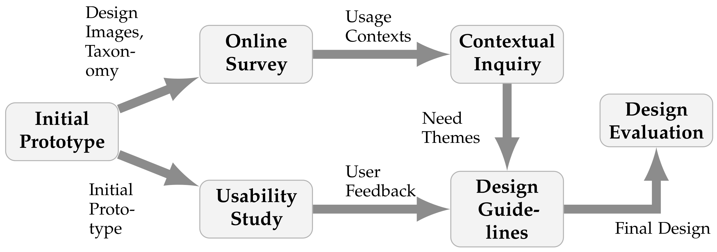
Robotic arms designed for industrial applications typically have well defined usage scenarios and task specifications. Since the WRF was a novel configuration, we needed to identify contexts where it would provide the most useful assistance, and the design features required to perform tasks in these contexts. Applying the principle of user-centered design [11], we collected feedback from potential end-users during the development of the robot. Starting with an initial low-fidelity prototype, three studies were conducted: an online survey, a contextual inquiry, and an in-lab usability study. Figure 1 shows the overall user-centered design process, that goes from abstract inquiries to concrete guidelines informing the final design. A full description of the design process can be found in [2].
2.1. Initial Design
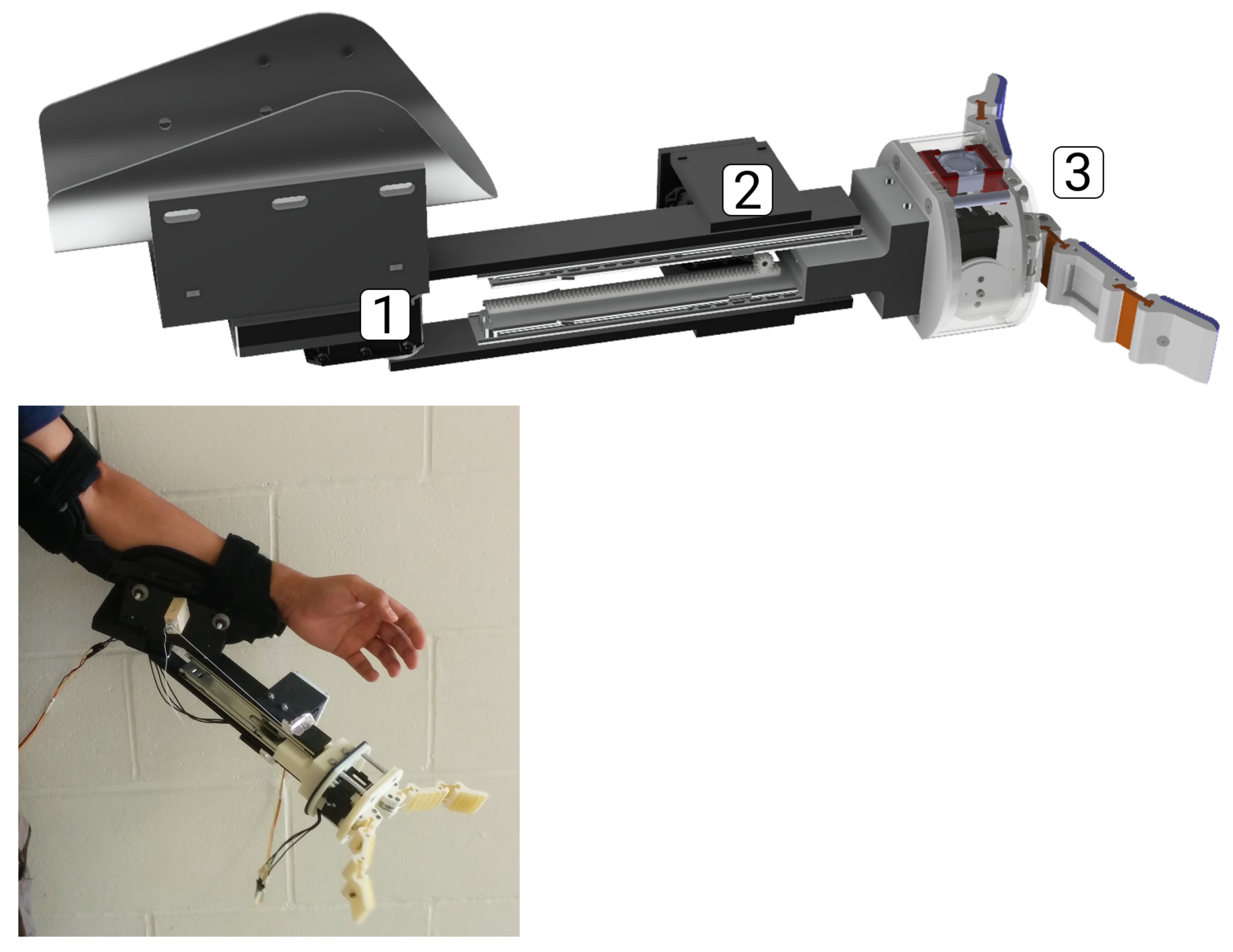
To keep the weight to a minimum while effectively increasing the wearer’s “wing-span”, the initial design included horizontal panning at the elbow and length extension as the degrees of freedom (DoFs), to allow for usage across multiple workspaces. The WRF Model I prototype was constructed out of acrylonitrile butadiene styrene (ABS) mounting components and stainless steel sliders, with a two-fingered gripper based on the Yale OpenHand T42 [12] as the end-effector, shown in Figure 2.
2.2. Online Survey and Contextual Inquiry
After constructing the prototype, we categorized usage affinity diagrams [13] into a taxonomy of usage contexts and functions (Figure 3) from a brainstorming session with colleagues to the question: “What would you use a wearable robotic third arm for?”
Using this taxonomy, an online survey was conducted on Amazon Mechanical Turk with 105 participants (57 male, 48 female). They were first asked to rate potential usage contexts for both classes of interaction (social/functional) with the prompts “A robotic third arm is useful for <context>”, and “I can see myself using a robotic third arm for <context>”. This was followed by similar prompts for rating the functions in both classes of interaction, and concluded with soliciting open-ended responses about desired features for the robot, and demographic details.
Participants considered the device to be more useful as a functional tool, particularly in tasks such as carrying objects and handling hazardous materials, than for social uses by a wide margin. They also considered it to be more useful in professional and military settings, and least in recreational contexts.
Informed by these results, a need-finding contextual inquiry [14] was conducted with a building construction crew on a university campus. The protocol for this inquiry was approved by the Cornell University Institutional Review Board (CU IRB) for human participant research (number 1611006802). The inquiry proceeded with guidance from a supervisor who offered expert testimony about the tasks of 10 workers. During and after observing their day-to-day tasks, workers were asked about the cognitive loads and common frustrations, which led to the identification of three usability “need themes”: assistance in reaching for objects and self handovers, stabilization of workpieces, and coordination of repetitive actions.
2.3. Usability Study
To generate actionable design principles grounded in physical interaction with the device as opposed to the previous conceptual inquiries, an in-lab study was conducted with users wearing the robot. In total, 14 university students (9 female, 5 male) participated in this study, which involved a semi-structured interview protocol (number 1608006549 approved by CU IRB). They began by describing a typical day in their lives, and were asked to imagine having a third arm attached to their body in some activities at home, at work, and performed for recreation. In order to narrow down their thought process towards the robotic arm, the same questions were repeated after showing them pictures of a 3D model of the prototype. Then they wore the robot and performed two scripted tasks: moving a cup on a table while seated, and handing over the cup to the interviewer. The robot was pre-programmed during these tasks, running an open-loop trajectory without feedback, sensing, or adaptation. Finally, participants were debriefed and asked for improvements and suggestions that they would like to see in future prototypes, and desirable features in a commercial product.
2.4. Design Guidelines
The verbal responses of the in-lab study participants were analyzed, and recurring opinions were grouped into common themes. For instance, multiple participants commented on the weight and ergonomics of the device (e.g., “It’s too heavy, definitely a strain on my arm”), and manipulation capabilities (e.g., “Gripping capacity should be better”, “More degrees of freedom [are needed]”).
The following guidelines and requirements for improving the WRF emerged from the responses to the contextual inquiry and the in-lab study:
- Weight and Balance: A majority of participants suggested reducing the weight of the robot, as well as selecting a more ergonomic attachment point to the human arm.
- Dexterity: Participants desired more dexterity than was presented to them at the end-effector, such as vertical pivoting for improved handovers and increasing the robot’s reach.
- Control and Autonomy: Participants suggested control schemes based on voice commands, and intention recognition from the wearer’s movements, with varying levels of robot autonomy based on the task scenario.
- Feedback: Most participants commented that the robot’s intentions were not clear throughout the usability study trajectories, suggesting that its intention be shown through lights, sounds, and voice feedback.
- Appearance: Participants suggested modeling the device on existing prosthetic devices, finding the idea of another human-like arm attached to their bodies to be discomforting. They also suggested selecting materials capable of handling hazardous substances.
2.5. Design Iterations
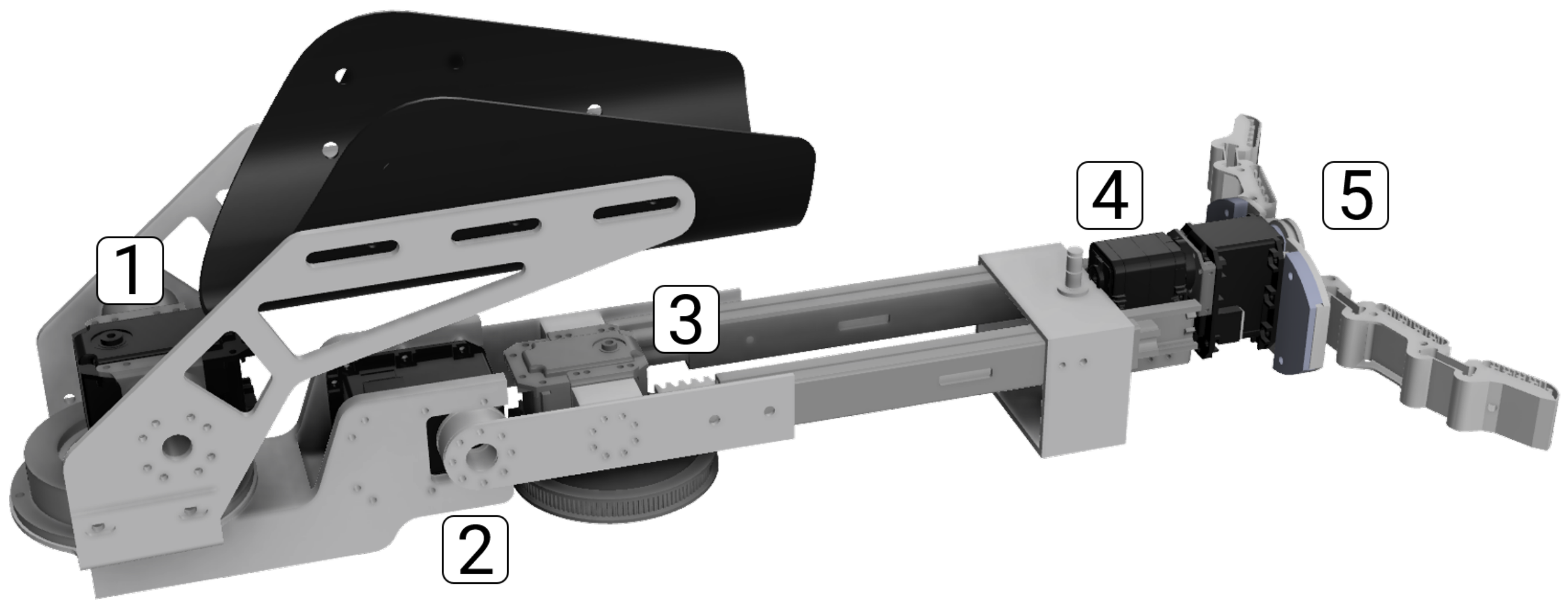
To address the concerns in the design guidelines, two additional degrees of freedom (DoFs) were added in the next WRF prototype (Model II): vertical pitching of the arm, and wrist rotation before the gripper (Figure 4). Additionally, the robot’s mounting point was shifted closer to the human elbow for improved ergonomic performance. This follows from the weight and balance of the robot being a consistent point of discussion. These considerations were balanced in trade-offs between ergonomics, motor power and robot dexterity, resulting in design improvements that allowed the robot to perform tasks similar to the contextual inquiry (Figure 5).
The vertical pitching, along with complete 360° panning, results in a full 3D workspace, and allows the robot to reach objects placed below as well as behind the user. The horizontal panning and vertical pitching DoFs are primarily responsible for bulk positioning of the WRF, while length extension further enhances its reach.
In the design of the wrist and end-effector, the most important trade-off is between dexterity and ergonomics. Articulated spherical wrists, including serial and parallel mechanisms, have been extensively studied and deployed in commercial and research robots [15]. A fully articular 6-DoF parallel mechanism, similar to a Gough–Stewart platform [16,17], was initially considered for the WRF’s wrist. However, based on the indicative usage scenarios discovered in the studies, a wrist with a single rotational DoF similar to human wrist pronation and supination was thought to be sufficient, along with rudimentary grasping capabilities with a two-fingered gripper.
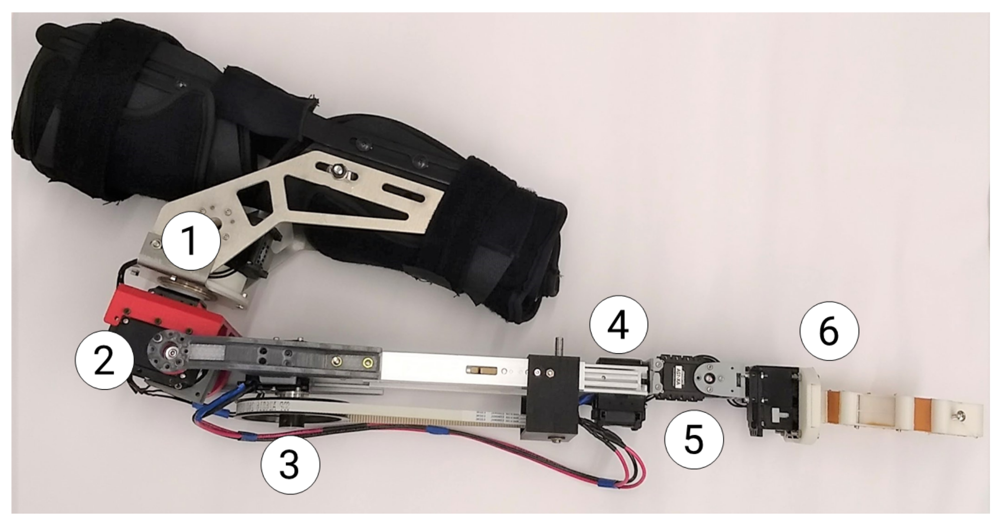
Following a pilot interaction study, described in detail in [3], more dexterity was desired from the WRF’s wrist, especially in pick-and-place tasks to orient grasped objects for handovers and drop-offs. As a result, in the final prototype (Model III), another DoF was added before the end-effector: vertical pitching of the wrist (DoF-5 in Figure 6). The other changes were to the place the DoF-2 motor right below DoF-1, and adding a planetary gearset at the output of DoF-2 with a 4:1 reduction.
3. Mechanical Design and Architecture
Following the progression in prototypes, in this section we describe the physical structure, actuators, and electronics architecture in the WRF’s hardware implementation, as well as the kinematics for Model III. Its features are summarized in Table 1.
3.1. Physical Structure
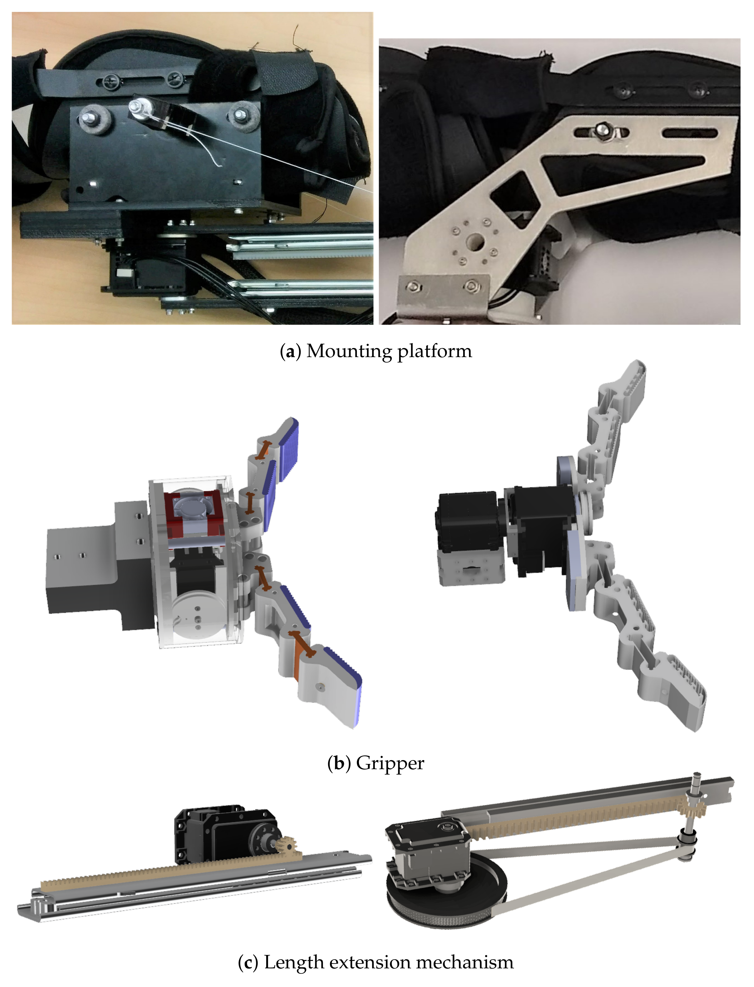
The WRF consists of an arm medical brace made of plastic, foam, and steel, used as the base for attaching the serial chain kinematic robot structure. Material selection played a major role towards weight reduction in the WRF from Model I to Model II. The ABS mounting platform for the robot was replaced with a waterjet-machined sheet aluminum structure (Figure 7a). Aluminum sliders were used instead of stainless-steel ones in the length extension mechanism, serving as both actuation and structural elements.
The initial gripper was designed after the Yale OpenHand Model T42 [12], adapted to constrain both fingers to move together using a single motor for weight considerations. In Model II, gripper finger sizes were reduced, and the motor housing and adaptor were removed, resulting in the motor body itself acting as a structural element connecting it to the previous DoF (Figure 7b). A serial mechanism in the form of a connector directly mounted on the motor horn of the wrist actuator was preferred over a parallel mechanism such as a four-bar linkage [18]. This is due to the mechanical simplicity, and lack in singularities within the workspace of a serial mechanism [19], as well as the fact that the motor body can itself act as a structural element in the relatively low-load applications for the WRF.
3.2. Actuation
The WRF was actuated with ROBOTIS Dynamixel servo motors. The horizontal panning and vertical pitching DoFs used MX-64T motors weighing 135 g each, with built-in proportional–integral–derivative (PID) feedback control for position and velocity, stall torque of 6.0 Nm at 12 V, and maximum speed of 63 rpm. These two DoFs required the most powerful motors since they were subject to the bulk of lifting and carrying loads. The length extension and gripper used smaller MX-28T motors, weighing 77 g with a stall torque of 2.5 Nm at 12 V, also with PID position and velocity control.
The wrist rotation and wrist pitching motors were subject to the least loads during operation, being at the end of the robot’s serial kinematic chain and not needing to generate contact forces for gripping. As a result, lower-end AX-12A motors were used for thes DoFs, with 1.5 Nm stall torque at 12 V, weighing 54.6 g each, and with only proportional feedback controllers for position and velocity.
The rack-and-pinion length extension mechanism in Model I was direct-driven, with the pinion gear mounted directly on the motor horn (Figure 7c, left). This design was updated to a belt-driven mechanism with a 7:1 transmission ratio and separated pinion gear, resulting in a faster extension speed and lower chance of slippage (Figure 7c, right).
Combined with aluminum sliders instead of steel, these design choices resulted in improved ergonomics and weight distribution.
3.3. Electronics
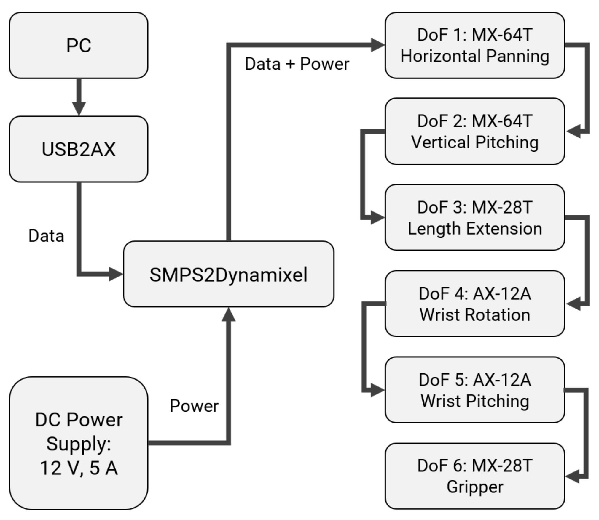
The motors in the WRF communicate at 1 mbps over a TTL protocol, attached serially in a daisy-chain fashion (Figure 8). The arm was tethered, receiving control commands from a PC, connected using a Xevelabs USB2AX v3.2a USB to TTL Dynamixel Servo Interface. It was powered by a 12 V, 5 A DC supply through an SMPS2Dynamixel Adapter. The MX-64T and MX-28T motors had onboard Cortex M3 CPUs, while the AX-12A had an Atmega8-16AU CPU.
3.4. Forward Kinematics
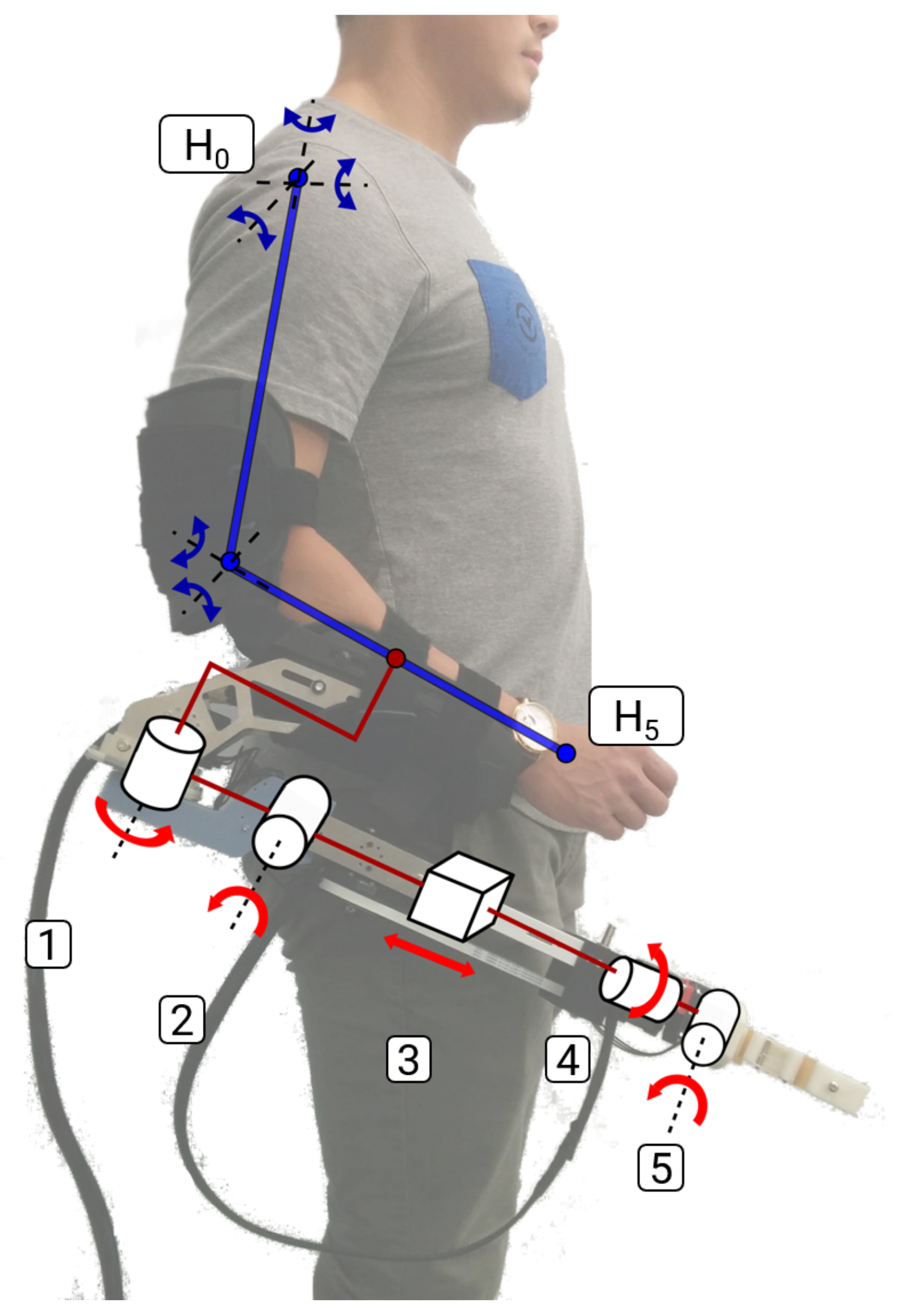
The WRF consists of a serial kinematic chain attached to the human forearm (Figure 9). Generally, the human arm can be represented as a 7-DoF chain [20]. However, since the robot’s motion is unaffected by human wrist movements, we used a reduced 5-DoF model, with three joints at the shoulder and two at the elbow.
The forward kinematics of each of these serial chains was described with coordinate frames derived using the Denavit-Hartenberg (D-H) convention [21], resulting in a homogeneous transformation matrix between the frame at the origin (human shoulder joint) and the frame at the human’s hand:
Here n = 5 is the number of joints, and are the D-H parameters for human arms.
In Table 2, (top), the anthropometric parameters and ranges of motion have been adapted from [20] and the NASA Man-System Integration Standards [22].
Similar to (1), transformation matrices can be constructed for the WRF models using the D-H parameters listed in Table 2, with m = 6 for Model III, and concatenating them with to get the transformation for the combined human–robot model:
To account for the attachment point offset between the human and robot, parameters for the fifth DoF in were modified to = 0.075 m, = 0.016 m in .
3.5. Inverse Kinematics
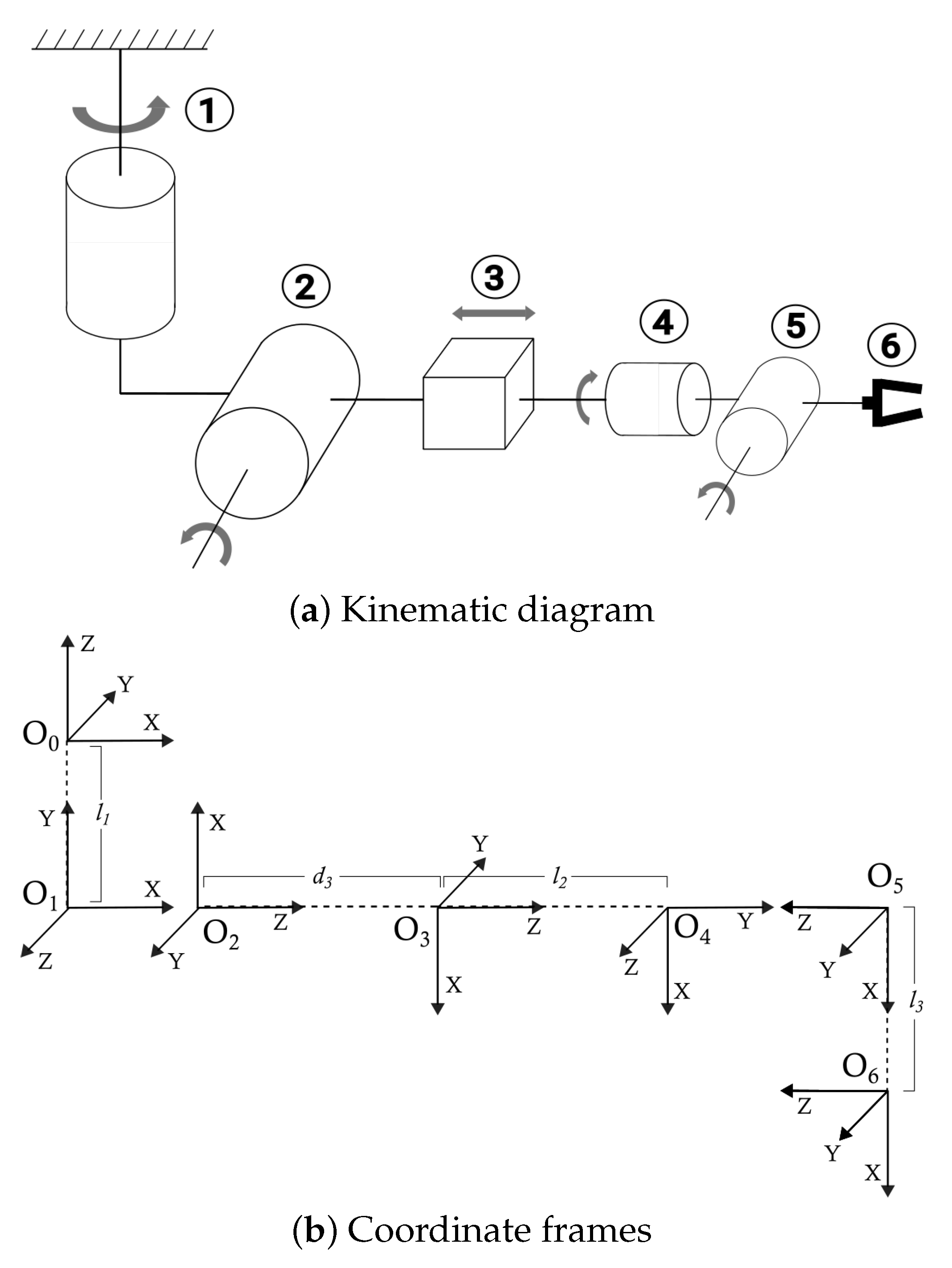
The inverse kinematics (IK) problem involves finding the values of the joint variables for a desired position and orientation (pose) of the end-effector. To find the IK for WRF Model III for a fixed human pose, we assigned coordinate frames according to the D-H convention, starting from the human arm attachment point, , to the mid-point of the robot end-effector’s fingers, (Figure 10).
The robot is over-constrained, having five articulated DoFs instead of six, resulting in no guaranteed solutions to the general position and orientation IK problem [23].
However, in most situations, the WRF’s wrist remains vertical, with . In this case, the position-only IK problem has an analytical solution in the first three DoFs. The position vector between the base frame and end-effector frame is a part of the transformation matrix , and can be written in terms of D-H parameters:
The joint variables for the first three DoFs can be computed for a given in terms of the parameters , , :
A more detailed analysis of the forward and inverse kinematics of the WRF, including for variable wrist orientations, has been presented in [24]. Another approach for solving the position-only IK problem with variable wrist orientation is by approximating the change in joint variables () required for a small change in end-effector position (). This involves determining the Jacobian matrix, J for the transformation between and , followed by computing its Moore–Penrose inverse (pseudoinverse) to find the change in joint angles [25]. Each element of the Jacobian matrix J is defined as:
For the WRF’s position-only IK, J is a 3 × 5 matrix such that:
This leads to the following approximate solution for , involving , the pseudoinverse of J:
This approach resulted in a fast computational method to implement IK for the WRF, further used for end-effector stabilization.
4. Preliminary Analyses
Along the development cycle, preliminary analyses were performed with the WRF prototypes to validate the changes in design. Model II significantly enhanced the user’s reachable workspace volume compared to Model I and the normal human range, while remaining within acceptable limits of biomechanical loads. These conclusions remain valid for Model III as well, indicating that at least physically, the WRF can be an effective augmentation without imposing unreasonable loads on the user.
4.1. Workspace Volume
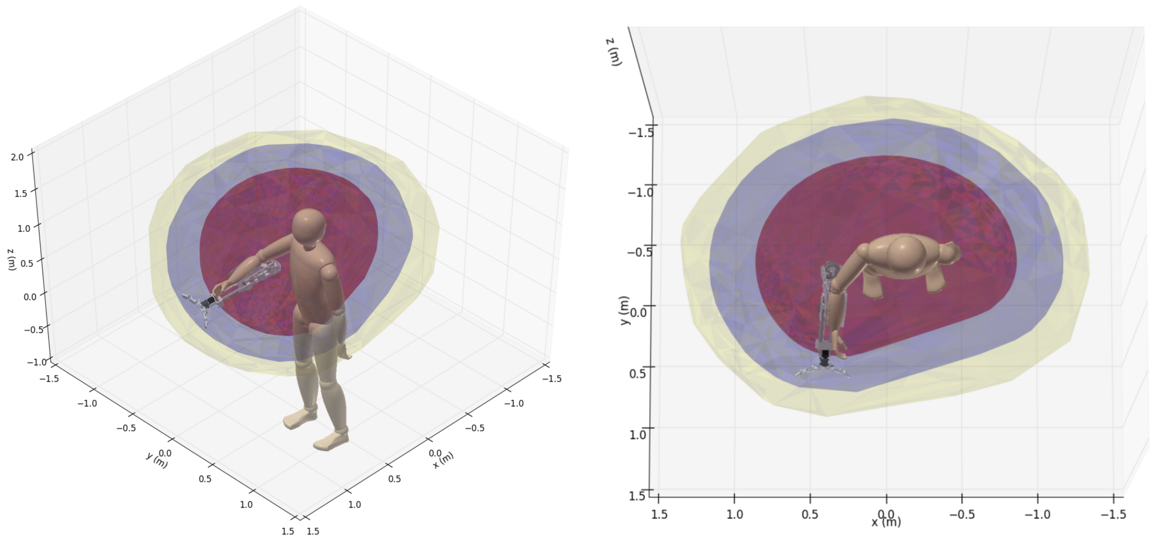
With the WRF, a user can reach objects farther than the normal human range. This enhancement was measured in terms of the total reachable workspace volume, which is the 3D region containing all possible end-effector positions when a mechanism undergoes its full range of motion (RoM).
Using a Monte-Carlo sampling procedure, point clouds of the end-effector positions were collected for the kinematic chains of the human arm, and combined human–robot chains with Models I and II, undergoing their full RoMs. These point clouds were decomposed into 2D horizontal slices, and numerically integrated along the vertical direction to compute the volumes, as described in [26].
The total reachable workspace volume for the human arm alone was found to be 1.003 m3. This was enhanced to 2.389 m3 while wearing Model I, an improvement of 138%. Wearing Model II further increased the total reachable workspace volume to 3.467 m3, an improvement of 246%, as illustrated in Figure 11.
4.2. Biomechanical Loads
The biomechanical loads on a wearer are an important consideration during prolonged usage of the WRF. In typical scenarios, such as those shown in Figure 5, the human’s arm remained fairly static, while the robot moved to fetch or grasp an object.
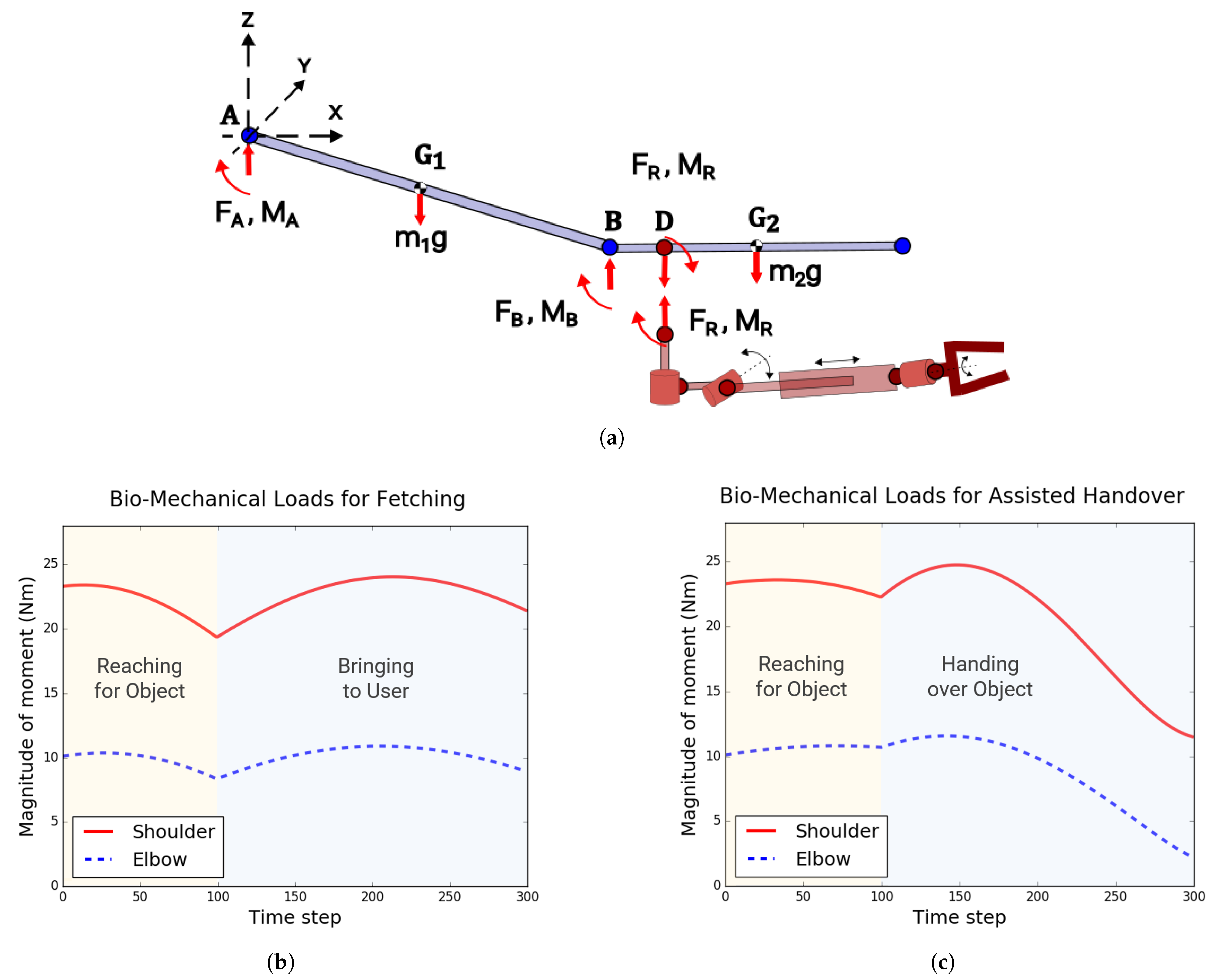
Building on the kinematics, as shown in Figure 12a, the dynamics of interaction between the human arm and robot was modeled as a point force and moment , considering them as separate bodies. The biomechanical load consisted of the force norms at the human shoulder and elbow: , , and corresponding moment norms: , . The statically determinate scenarios, fetching from below (Figure 5c), and assisted two-person handover (Figure 5d), were considered for this analysis. The forces and moments in these scenarios were computed using the iterative Newton–Euler dynamics algorithm [27].
The peak moment loads on the wearer’s shoulder and elbow during these tasks were ~24.8 Nm and ~11.6 Nm, respectively, (Figure 12b,c). The peak force loads were ~55.8 N at the shoulder , and ~31.3 N at the elbow . For comparison, the human shoulder can withstand moment loads of magnitude ~85 to 130 Nm and force loads of ~100 to 500 N, while the elbow can withstand moments of ~40 to 80 Nm and forces of ~50 to 400 N [28,29].
The anthropomorphic parameters (link lengths, masses, inertias) for the workspace volume computation, as well as biomechanical load analysis, have been adapted from the NASA Man-System Integration Standards [22].
Details on the procedures for computation of workspace volumes and biomechanical loads can be found in [3]. Concurrent to this article, we have also conducted a more detailed inquiry into the biomechanical effects of the WRF’s motion on the user’s body at the musculoskeletal level, and have developed trajectory optimization techniques to generate motion plans for the WRF that minimze these effects [30].
5. End-Effector Stabilization
Having established that the WRF enhances a user’s reachable workspace volume while remaining within ergonomic biomechanical load limits, we now consider the interaction effects between the user and the robot. During collaborative activities, disturbances are introduced in the robot’s motion plan due to the user’s independent arm movements. In order for the WRF to be an effective augmentation, it needs to be able to counteract these disturbances. In this section, we describe strategies for stabilizing the WRF’s end-effector while it is worn by a user performing close-range tasks.
We had previously achieved promising stabilization results for small, 2D planar movements using time series forecasting of human arm motion [4]. This approach was extended here to include a recurrent neural network (RNN) model for human motion prediction, and applied to 3D stabilization in five common tasks such as wiping a desk and stowing items into drawers.
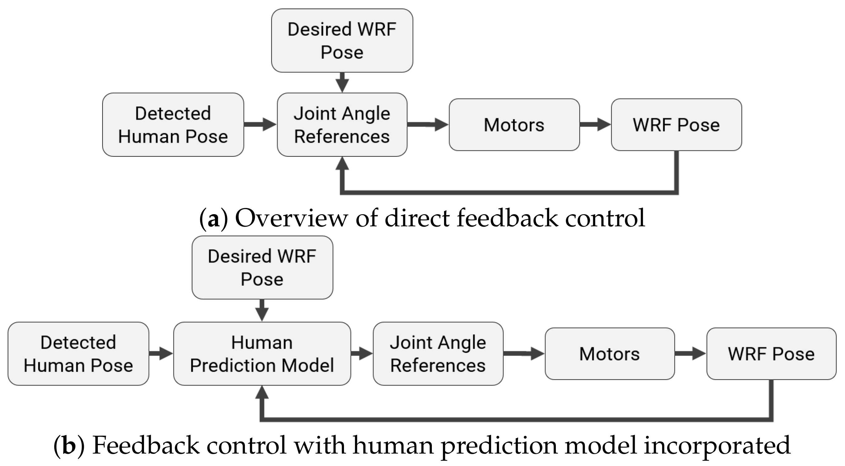
A direct feedback control strategy is outlined in Figure 13a. The joint angle reference signals for each motor are determined from the poses of the human and WRF detected by an optical motion capture system, as well as the desired pose of the end-effector. The aim is to stabilize the end-effector at a static position in 3D, with the relevant joint angles computed using the inverse kinematics described in Section 3.5.
It was discovered in [4] that, while the WRF’s actuators possess sufficient bandwidth to be effective in a direct feedback control strategy even with stock tuning, in practice, their performance is hindered due to sensing and actuation delays. A predictive approach, where the user’s arm motion is determined over a finite horizon, was found to mitigate these effects. Linear system identification techniques were applied to estimate the delays and determine the prediction horizon.
Two approaches were considered for predicting human motion over this horizon for extended tasks in 3D: an autoregressive (AR) time series model as in [4], and a recurrent neural network (RNN) model adapted from [31]. These models take in the poses for the WRF and human, and generate a sequence of joint angle references over the time horizon. Both of these approaches were trained offline using the KIT Whole-Body Human Motion Database [10] and adapted for online predictive control through the framework shown in Figure 13b.
5.1. System Identification
As a precursor to the application of human motion prediction for stabilizing the WRF, the dynamic response of its motors were studied in typical usage scenarios, and system identification was performed to recover the in situ motor parameters for Model III. This allowed for the estimation of sensing and actuation delays in the physical system by augmenting a delay term to the linear models, and fitting to data from the motion capture system.
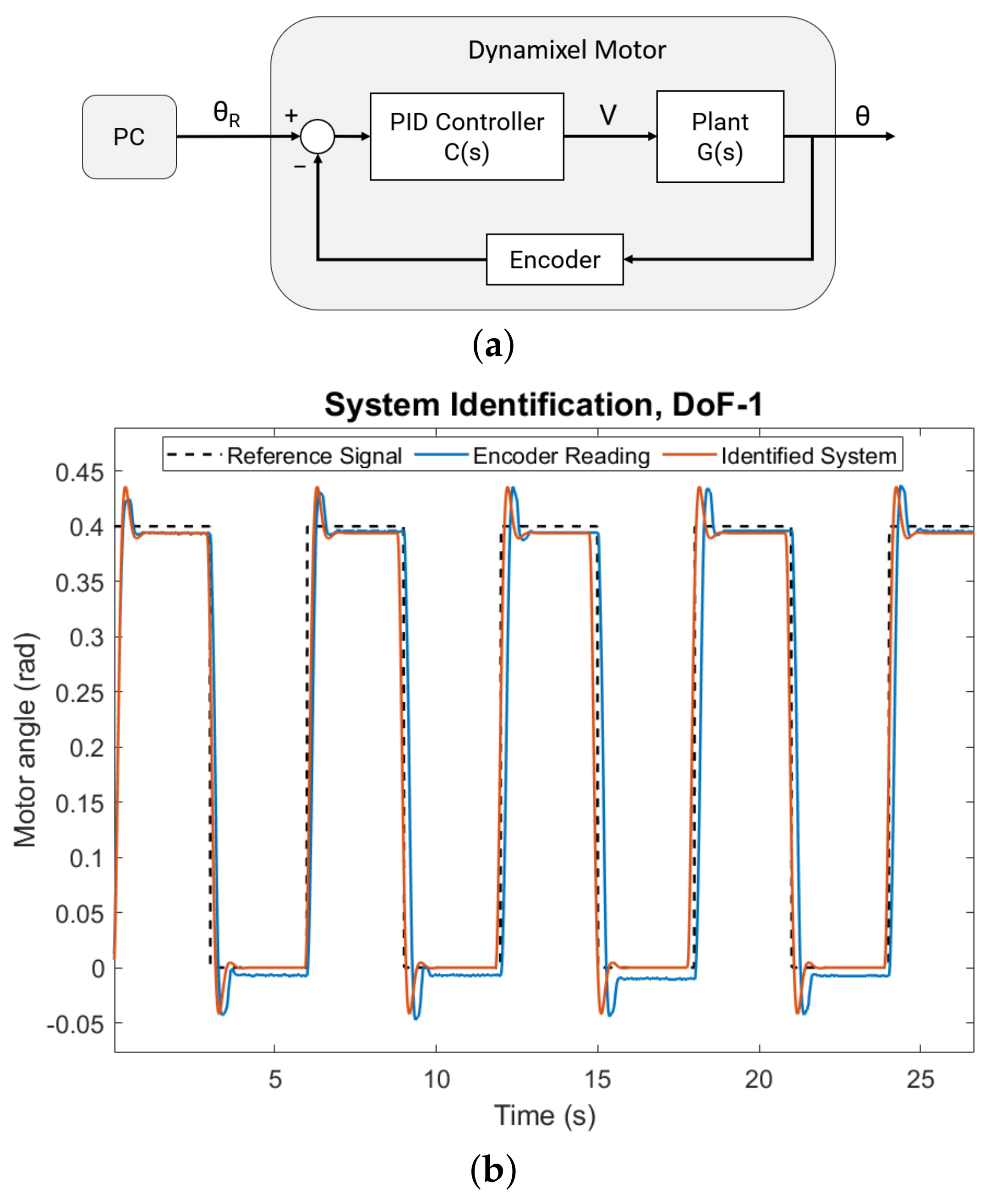
Each of the Dynamixel motors used in the robot have built-in PID controllers, apart from the AX-12A motors for wrist rotation and pitching that only have proportional control. Each motor receives a reference angle as input from the PC, driving a DC motor plant, with output angle measured using built-in encoders (Figure 14a).
The plant transfer function between voltage V and output angle is based on an L-R circuit DC motor model [32], resulting in a third order system in terms of parameters , and :
During system identification, the PID controller’s transfer function used manufacturer supplied values for the gains , , and . This resulted in the closed-loop transfer function between the motor output angle and reference signal to be a third-order system with no zeros:
The closed-loop model parameters and were fit to the measured output signals using the Simplified Refined Instrumental Variable method for Continuous-time model identification (SRIVC) method [33]. No explicit delays were assumed in this transfer function since the encoders are built-in to the motors. The plant parameters , and were then obtained from and . Each DoF was identified individually, keeping all other motors fixed, and the magnitudes of the step reference input signals were determined from the usage scenarios (e.g., steps of 0.7 rad over 2 s for DoF-1 as shown in Figure 14b).
The accuracy of the identified system models was evaluated by computing the Normalized Root Mean Squared Error (NRMSE) goodness of fit between the output signals measured by the encoders and the simulated motor model outputs, for the same reference input. The plant parameters and model fitting metrics for each DoF are listed in Table 3.
Having obtained the open-loop plant transfer function parameters for each of the DoFs in the WRF, we can use augment these models to estimate the sensing and actuation delays in the overall system.
5.1.1. Delay Estimation
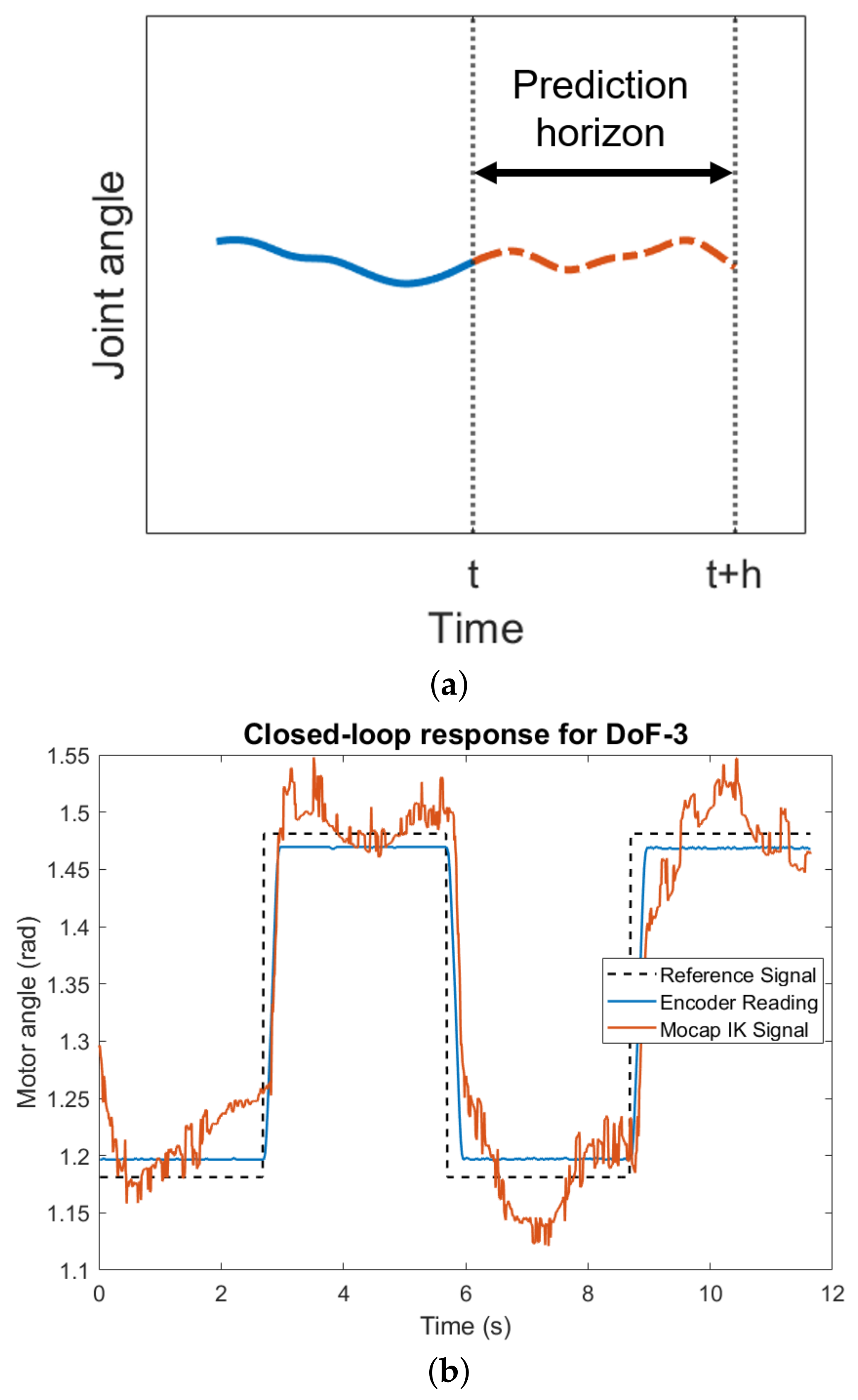
The first step in developing predictive models was to estimate the time horizon for predictions over which the WRF’s motors need to be controlled to compensate for sensing and actuation delays. This time horizon h (Figure 15a) was determined by system identification using the linear model described in Equation (10) with a delay term included:
is the motor response to an input step signal , reconstructed though the inverse kinematics equations in Section 3.5 using data from the motion capture system (Figure 15b). The other terms in the transfer function, and , were obtained from the system identification performed earlier by using the parameters in Table 3 and the stock PID control gains , , and . This allowed for the isolation of system delays in the motion capture and communication channels from the in situ motor dynamics.
The delay was estimated to be 86 ms using the same SRIVC method as before, averaged across DoFs 1–3 which showed relatively slower responses due to larger loads. This corresponded to a prediction time horizon h of about 10 time steps for the OptiTrack motion capture system used in this work with a frame rate of 120 Hz [34].
5.2. Previous Work on Planar Stabilization
In previous work [4], we had developed an end-effector stabilization strategy for a reduced 2D scenario. The positions of the WRF’s base and end-effector were tracked using fiducial markers and a stereo camera (Figure 16a) while the user’s arm moved in a periodic manner in the XY plane with small displacements of ~15 cm from an initial position at frequencies typically less than 1 Hz.
Using the identified linear system models through the procedure described in Section 5.1, the step response charactersitics were estimated for the DoF-1 and DoF-3 motors (Table 4). In particular, the bandwidth for both motors was found to be above 1 Hz, which should have been sufficient to stabilize the WRF against small, planar human arm motions through a direct feedback control strategy (Figure 13a). However, this performance was affected by delays in sensing and actuation.
After estimating these delays using similar linear models (Section 5.1.1), an autoregressive (AR) time series model for human arm motion was developed to determine the joint angle reference signals for DoF-1 and DoF-3 using the approach shown in Figure 13b to stabilize the end-effector in 2D. Compared to a direct feedback control approach, the AR model helped reduce position errors by 19.4% in X and 20.1% in Y (Figure 16b).
Related work in this domain includes stabilization of SR limbs using a time-series model of the forces and torques due to the wearer’s change in posture [35], as well as modeling of hand tremors as Fourier series for tool-tip compensation in a handheld surgical device [36]. This literature informed the choice of AR models for predictive control of the WRF, both in [4], as well as being applied to the full 3D case here.
5.3. Human Motion Prediction
The estimated system time delays for the WRF served as prediction horizons for the human motion prediction models for end-effector stabilization. The criteria for these models were real-time (or close to real-time) prediction with optical motion capture data, and good performance over the required controller time horizon in close-range tasks.
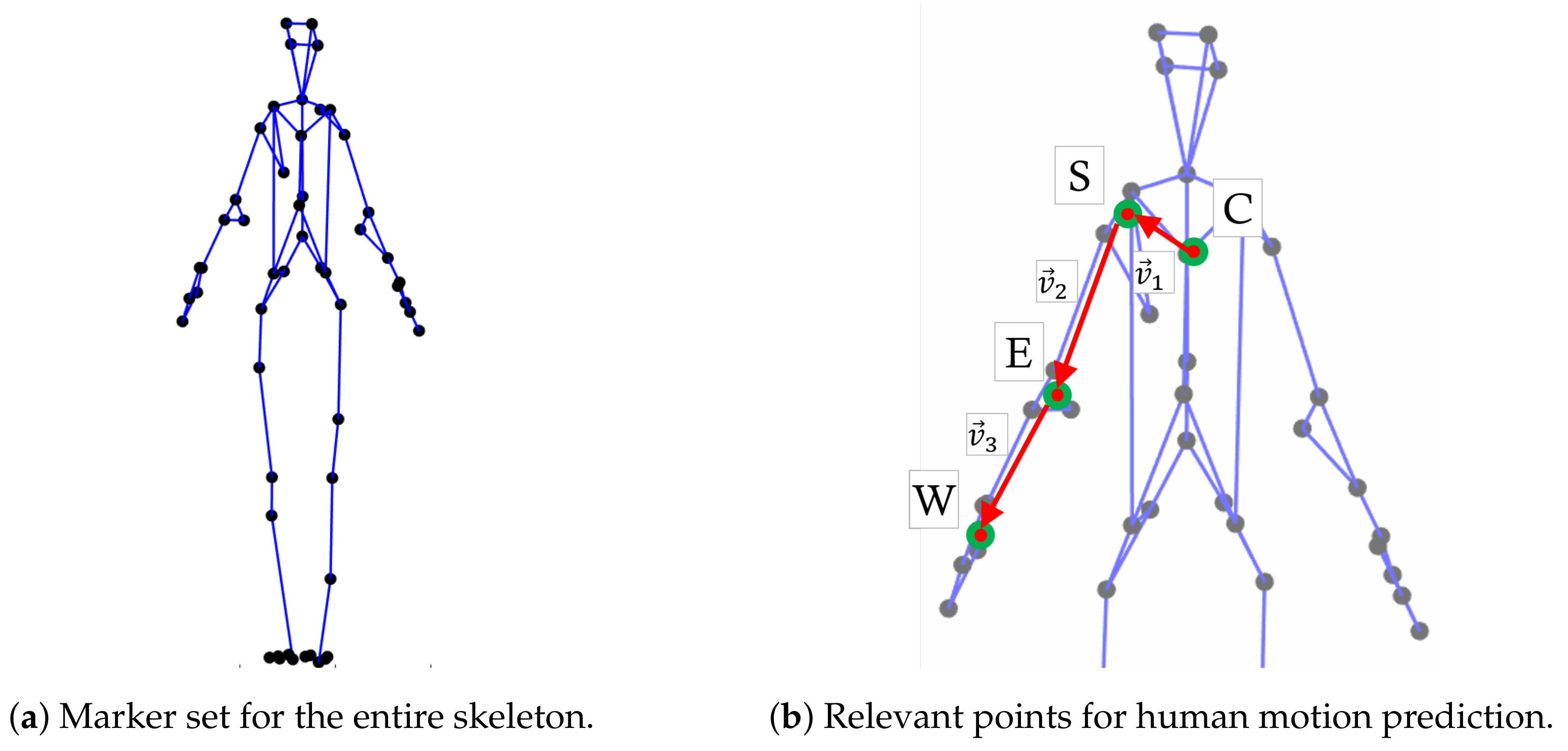
Two methods were utilized for this purpose: an autoregressive (AR) time series model, and a single-layered gated recurrent unit (GRU) adapted from [31] and modified for real-time performance. Both of these models were trained offline using the KIT Whole-Body Human Motion Database [10], available at [37]. It consists of a wide selection of task and motion scenarios, with annotated recordings from optical motion capture systems, raw video, as well as auxiliary sensors (e.g., force plates). For this work, we utilized labeled human skeleton marker data (Figure 17) from nine tasks in the database that involved periodic movement of the subject’s right arm. They are listed in Table 5 along with the number of trials performed for each task, and the total number of data points with human right arm movements extracted from all trials.
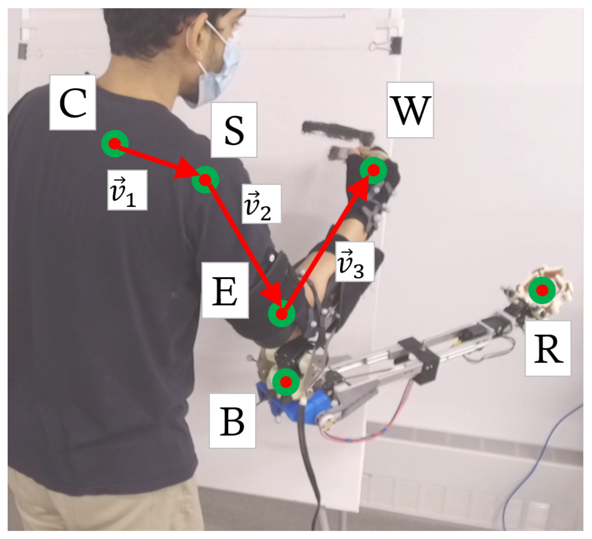
The full-body skeleton marker set consists of 56 points, out of which 10 are relevant for prediction of human right arm motion, with the positions on the body determined by a weighted sum of the individual 3D positions of the markers (Figure 17b): 3 for the clavicle (C), 3 for the shoulder (S), 3 for the elbow (E), and 4 for the wrist (W).
Three relative position vectors were generated from the four body points: , , and . This allowed for prediction of movements of a particular body segment independent of its previous neighbor, and improved the training accuracy of the models.
5.3.1. Autoregressive Time Series Model
As in [4], the time series model started with the initial assumption of an Autoregressive Moving-Average (ARMA) process:
Here is a discrete univariate series, composed of a constant term C, past terms weighted by coefficients for lag k (AR term), and past white noise terms weighted by the coefficients . The number of past terms, p and q determine the orders of the AR and MA parts, respectively.
Each component of the relevant body vectors , and , was considered to be an independent univariate series. The stationarity of these series was verified with augmented Dickey–Fuller hypothesis tests [38].
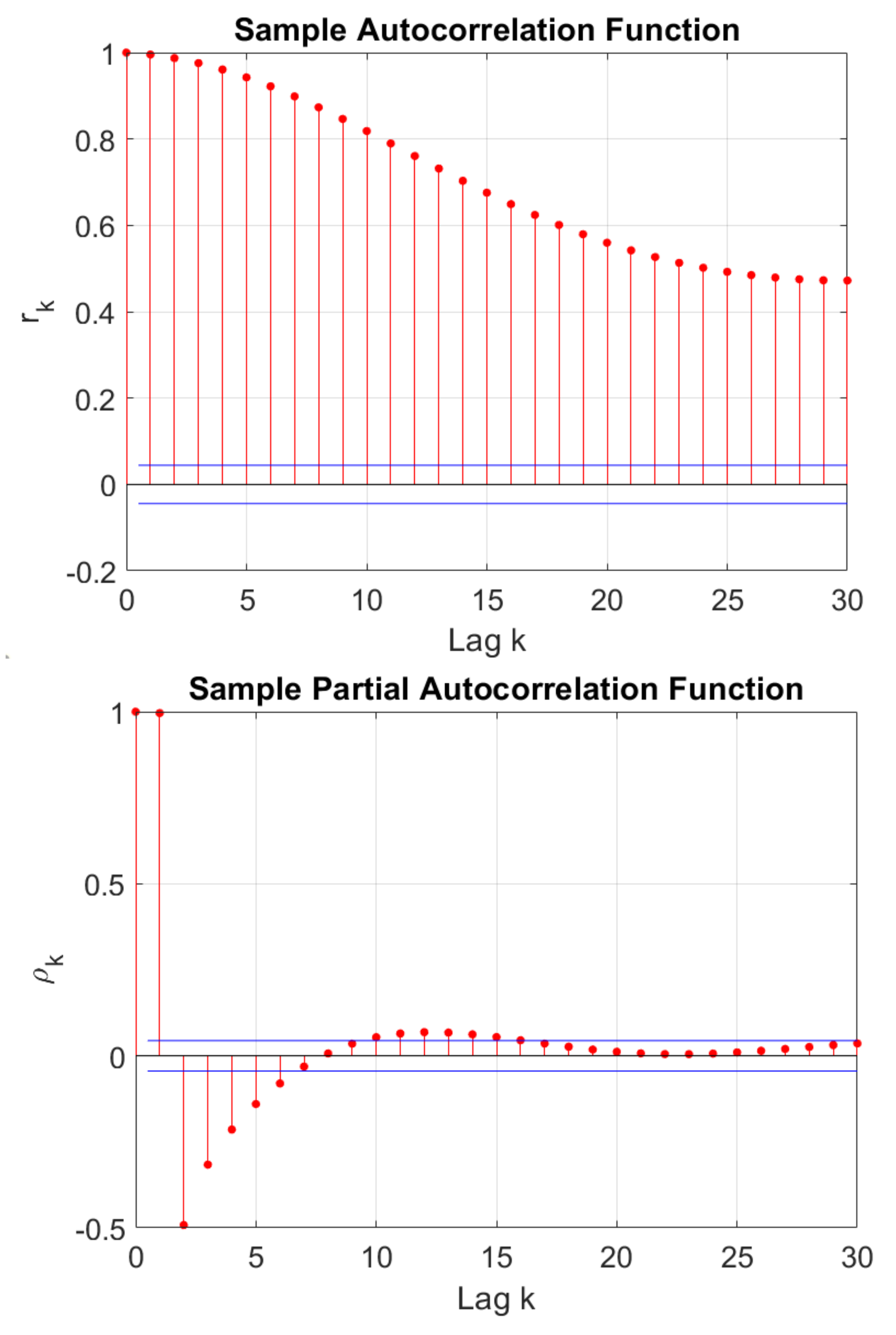
The autocorrelation () and partial autocorrelation () functions at lags k were computed for these series. There were sharp drop-offs in compared to over successive lags for each component of the body vectors, illustrated Figure 18 for the X component of . This indicated that the ARMA processes could be simplified into purely autoregressive (AR) models [39]:
The model order p for each of the nine components in the body vectors was determined using the Akaike Information Criterion (AIC), a maximum-likelihood measure of the goodness of fit [40]. The AIC was computed for model orders up to 30 for each of the nine series, and the one with minimum AIC was selected as p for that series. The minimum AIC values were obtained at different model orders for each series, ranging from p = 18 to p = 25. The model parameters , C, and were determined using the Yule–Walker method [41], trained on the task motions listed in Table 5.
5.3.2. Recurrent Neural Network Model
While an AR model is able to forecast human motions through local predictions, it does not capture dependencies over a longer time period, or encode structural information about the correlations between body components over time. To account for these factors and improve on the predictions from the AR models, we used a recurrent neural network (RNN) model for human arm motion prediction, and compared the performance between the methods.
Independent of robotics, RNNs have been applied extensively for human motion prediction, including architectures with Long-Short Term Memory (LSTM) cells [42], and structural RNNs that encapsulate semantic knowledge through spatio-temporal graphs [43]. These approaches include multiple recurrent layers as they are aimed at offline prediction of the entire human skeleton, and task classification in general motion scenarios. As the task scenarios for WRF stabilization involve periodic motions and require prediction of only the wearer’s arm, we used a simpler model with a sequence-to-sequence architecture [44] and a single Gated Recurrent Unit (GRU), as proposed in [31], which also includes a residual connection for modeling velocities. Compared to an AR model, this resulted in higher prediction accuracy of human arm motion, and improved the end-effector stabilization in most task scenarios.
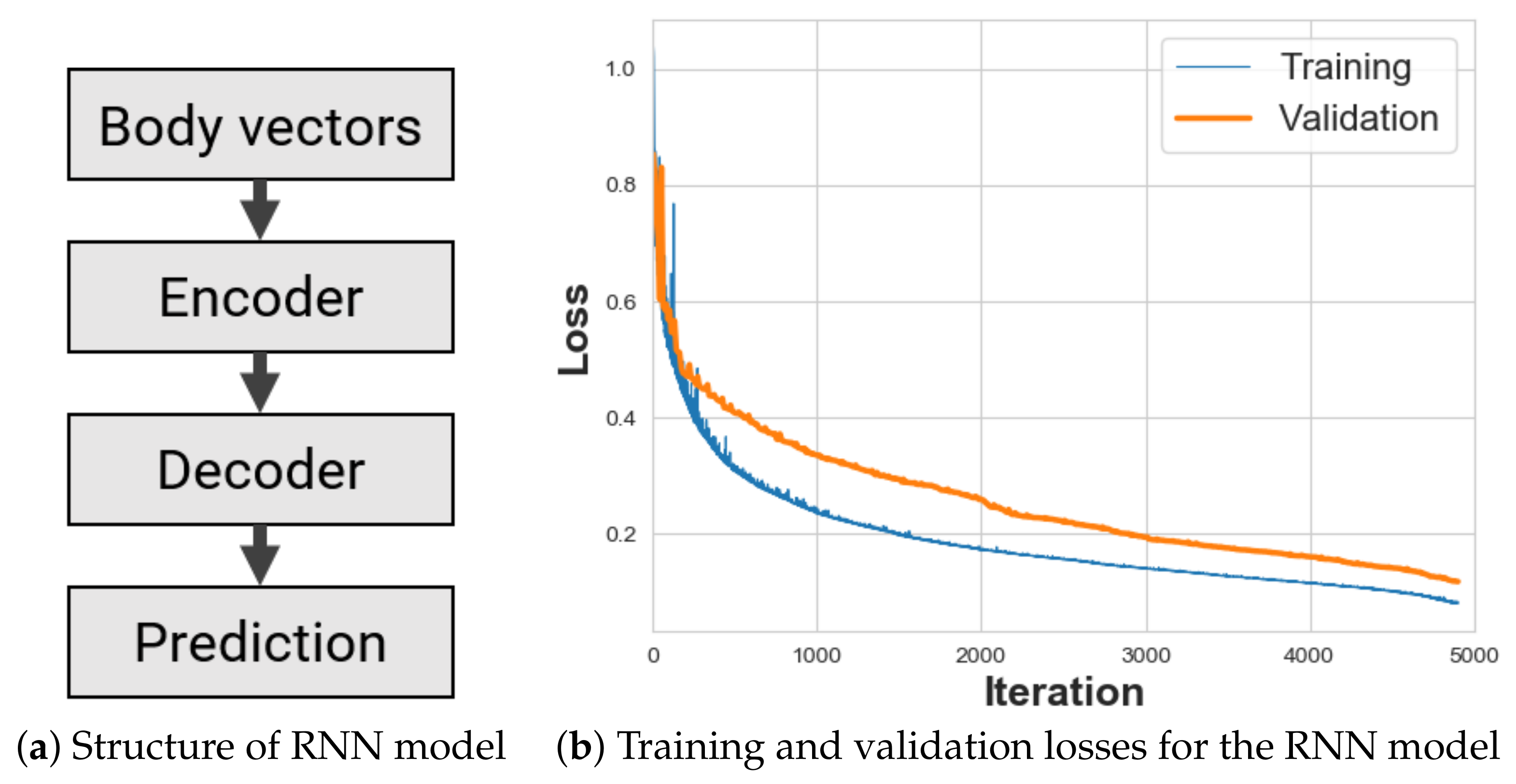
The schematic of the RNN model is shown in Figure 19a. It consists of an encoder network that takes in a 9-dimensional input of the body vectors, , 50 frames at a time from the KIT database or motion capture system, and a decoder network that converts the output from a single GRU cell with 1024 units into 9-dimensional predictions over k steps. Based on the estimated system delay, we set k = 10, and the learning rate to be 0.05 for batch sizes of 16, as specified in [31] for predictions up to 400 ms. This RNN model was trained on the KIT Database motions listed in Table 5, and converged at about 5000 iterations, as shown in Figure 19b with Mean-Squared Error (MSE) losses.
5.3.3. Model Evaluation
Both models were evaluated on the relevant motions from the KIT Database listed in Table 5. They were trained offline using all but two trials for each task, with one of remaining trials serving as the validation set, and the other as the test set. The training set was expanded to four times its original size by adding Gaussian white noise with standard deviation 1 cm to each of the nine components of the body vectors, leading to 89,864 data points for training. The test and validation sets had 18,922 and 15,042 data points, respectively.
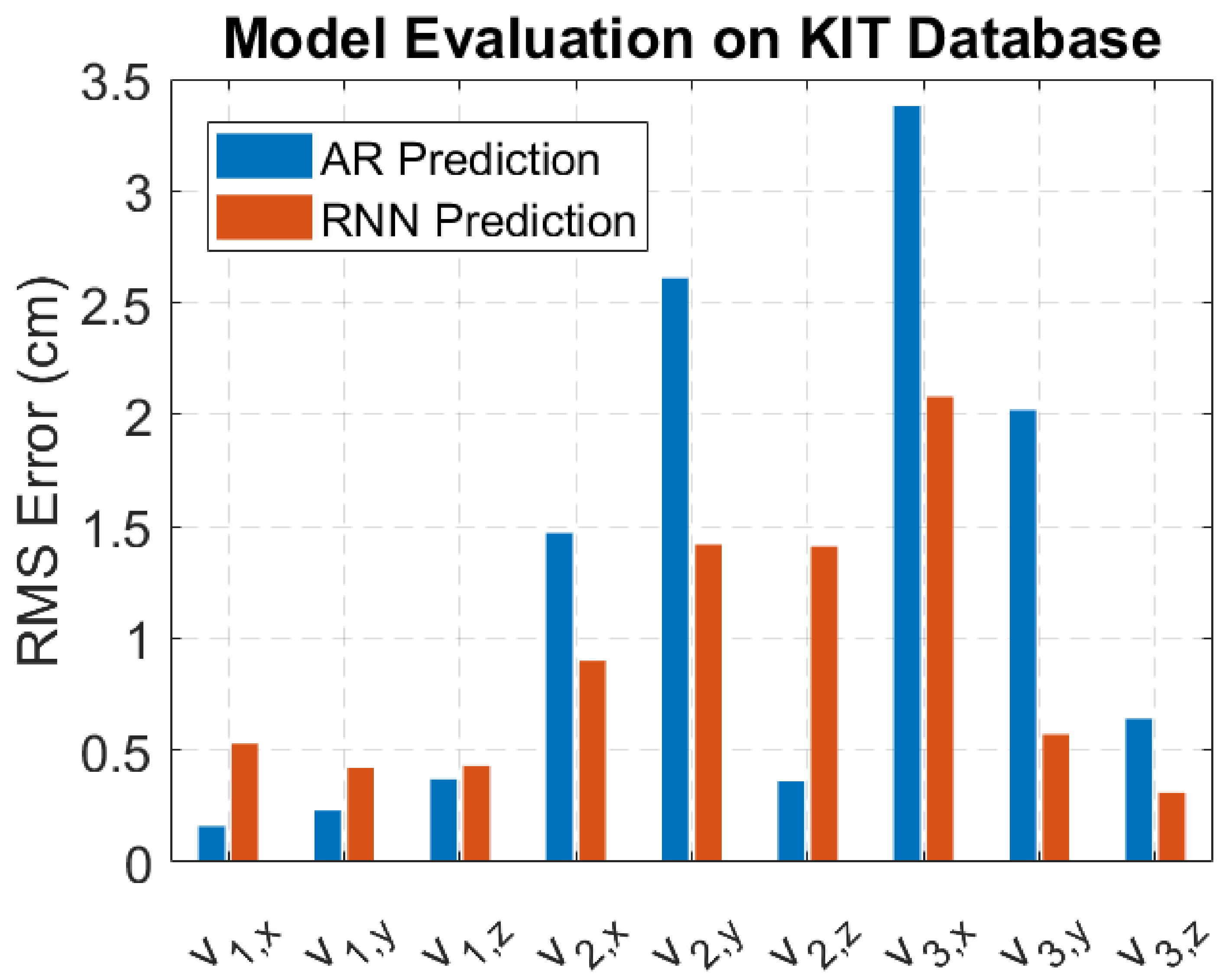
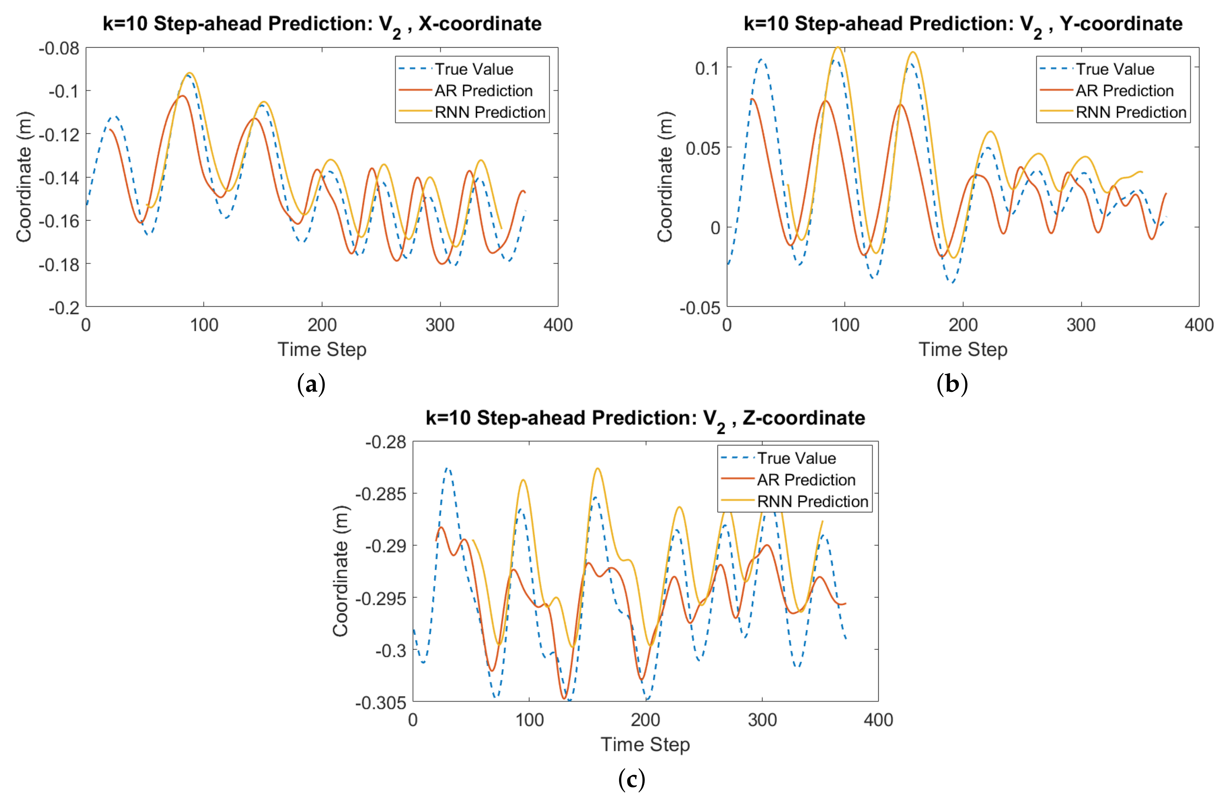
The Root-Mean-Square (RMS) prediction errors were computed on the test set for both models, and are listed in Table 6. While the RNN model did not improve upon the AR model for every component, it reduced the prediction errors in the components with the worst performance using AR (Figure 20). The RNN model also performed better overall, with an average RMS error of ~0.90 cm, compared to ~1.25 cm for the AR model. Figure 21 shows that while the RNN model tended to overshoot the ground truth, and be offset from it, the tracking of overall motion trends was better than the AR model.
5.4. Implementation on the WRF
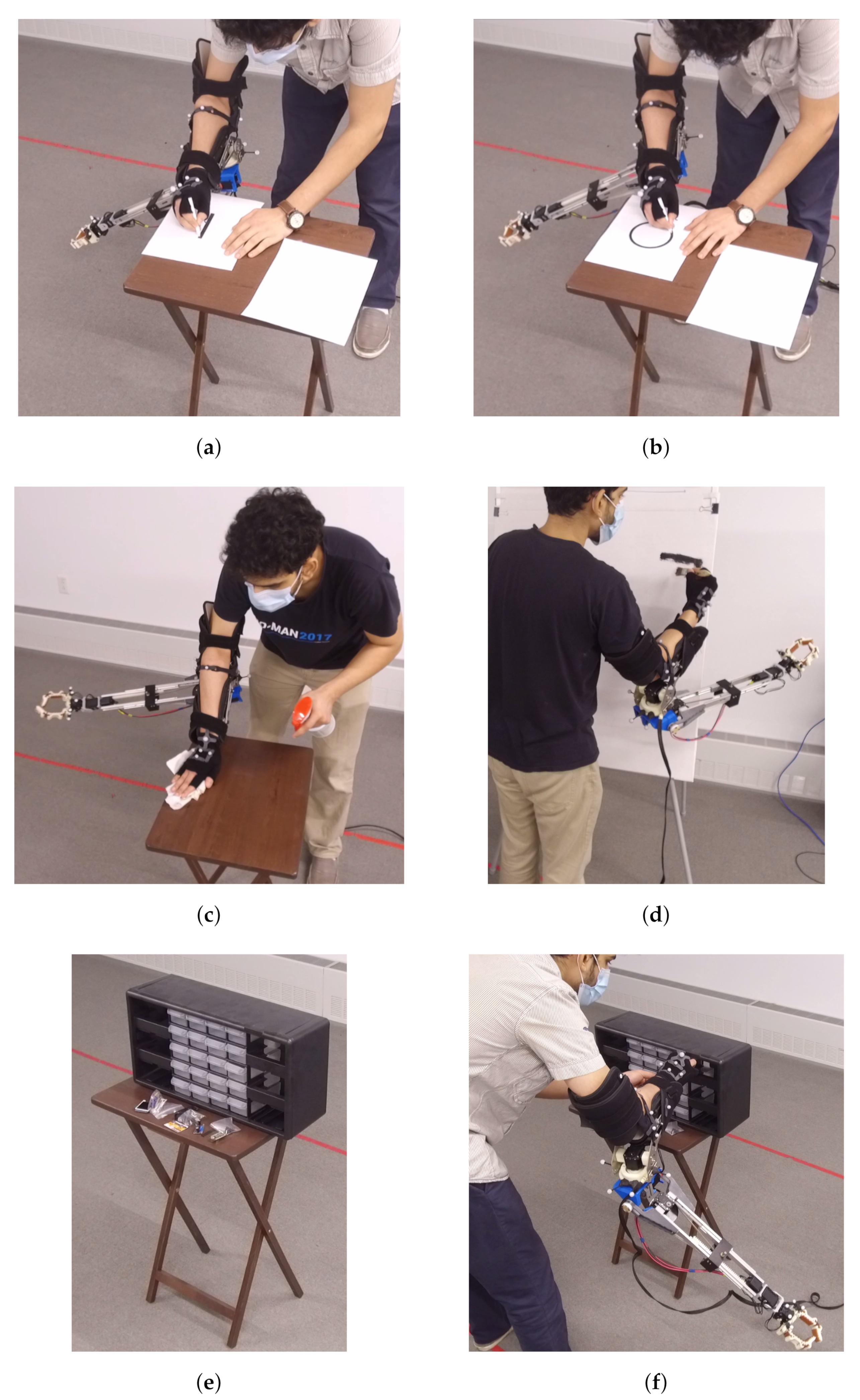
Having obtained two predictive models for human arm motion that performed well on the KIT Database, they were applied for stabilization of the WRF’s end-effector at an initial pose when subjected to disturbances due to movement of the user’s right arm. For validation of these models, we considered five task scenarios, shown in Figure 22, that involved periodic arm movements of relatively small magnitude—(a) tracing a line of length 10 cm, (b) tracing a circle of diameter 10 cm, (c) wiping a desk top, (d) painting with small brush strokes on a canvas, and (e) placing ten objects into shelves of a table-top drawer unit. Each task was performed for ~5 min, with each iteration lasting between 5 s (for tacing lines) and 30 s (for placing objects) depending on the complexity of the task. The initial end-effector pose was selected to be on the right of the user and below them, so as to not impede the task.
Optical markers were placed on the user’s right hand and elbow, as well as on the WRF’s end-effector and near the DoF-1 motor (Figure 23).
These markers were tracked at 120 Hz using an OptiTrack motion capture system [34]. The raw marker position data was smoothed and filtered using an IIR low-pass digital filter with transfer function coefficients for 6 Hz normalized cutoff frequency [45], following the techniques discussed in [46,47].
In all the scenarios shown in Figure 22, the body vector was assumed to be constant in each task, as the human shoulder and torso remained almost stationary at their initial positions. The other relevant points, B (base position of the WRF), and R (position of the end-effector), to be tracked are shown in Figure 23, We aimed to keep the end-effector static at the initial point at the start of each task. If the user’s arm were to move, the end-effector would also move by an amount at time t. To generate appropriate setpoints for the WRF’s motors, is converted from the a global frame G (fixed lab frame) to the robot’s base frame B. Using the convention for the homogenous transformation of the pose of frame B as seen in frame A, we need to convert from to . Using the elbow frame E as an intermediate,
The transformation between the robot base B and elbow E is constant, while the transformation consists of two variable parts: the rotation matrix between the elbow and ground frames, and the position of the elbow, which is tracked directly by the motion capture system. is the rotation matrix that takes the unit vector along the local X-axis, , and aligns it with the unit vector along the human forearm, , in the ground frame. Using the approximate method for position-only inverse kinematics (Jacobian pseudoinverse) discussed in Section 3, the change in WRF joint variables can be determined:
At time t, this gives the desired setpoint reference for each motor used for direct feedback control:
Following the procedure shown in Figure 13b, the predictive models were used to generate setpoint references over a time horizon of ~86 ms for each motor in the WRF:
For a stereo camera frame received at time t, a sequence of k = 10 joint angle references were sent to each motor, with ms, . As described above, is the desired joint angle in direct feedback control, computed using inverse kinematics for the detected human and robot poses at time t. The predictions from the AR and RNN models are represented as residuals added to .
During implementation, it was found that the AR model could generate predictions nearly in real time, though requiring a few seconds of sensor data collection to initialize the predictors at the start of each task. In comparison, the RNN model had lags of up to ~50 ms due to computational bottlenecks when predicting over the specified time horizon. To account for these lags, the pre-trained RNN model was executed in parallel with the AR model. Until a prediction was received from the RNN model, the AR prediction was used for computing . Depending on the amount of lag, determined through time stamps, a corresponding number of RNN predictions were discarded (typically the first 5–6 terms), and the remaining ones were added to the sequence to be sent to the motors.
This implementation of human motion prediction (RNN + AR) reduced the mean error in end-effector position by up to ~26 % over direct feedback control, while the AR model alone was able to improve upon direct feedback control by up to ~19 %, as listed in Table 7. Figure 24 shows that the performance of all three control methods varied according to the task, with more structured and periodic motions such as tracing a line and circle showing better stabilization performance compared to motions with less structured or periodic behavior such as stowing items into a drawer.
6. Conclusions
This paper summarized a novel configuration for a wearable supernumerary robotic (SR) arm aimed at close-range human–robot collaboration, and studied the performance of human motion prediction for stabilizing its end-effector in illustrative usage scenarios.
6.1. Design
The robot’s design process was driven by usage contexts determined through taxonomy development and surveys; specific functions were then derived from need-finding through contextual inquiry with construction workers, and further informed by a laboratory study with a physical robot prototype. This process was published earlier in conference proceedings [2]. These led to a robot design that increased the human-reachable workspace by 246%. Furthermore, it supported picking up objects for self-handovers, assisting in human-human handovers, and providing object stabilization. The design added action capabilities while being low in weight and well-balanced enough to stay within human biomechanical load limits. These results were published earlier in conference proceedings as well [3]. Since then, following further interaction studies, another design iteration led to a more dexterous prototype of the WRF, Model III, with five articular DoFs. Additional descriptions of the mechanical architecture, forward and inverse kinematics, and actuation systems of the WRF have been provided here.
6.2. Predictive Control
Linear system identification was performed to estimate the delays in sensing and actuation used as time horizons for the human motion prediction models. Previously published work involved 2D planar stabilization of the WRF’s end-effector with small human movements [4]. The primary contribution of this article is the extension of this work to 3D scenarios with a wider range of human movements. The human motion prediction models took the form of an autoregessive time series and a recurrent neural network, both trained and validated offline on the KIT Human Motion Database.
These trained models were tested directly on the physical system, resulting in lower mean position errors of the end-effector compared to direct feedback control. However, the absolute improvement in performance was relatively small for the tasks considered here. A potential solution could involve using more powerful and heavier actuators with greater bandwidths, though resulting in larger loads borne by the user during operation. Along with vision-based sensing, systems with wearable sensors such as Inertial Measurement Units (IMUs) mounted on the human and robot might help improve performance.
6.3. Future Work
Extensions of this work can include stabilizing over a trajectory in free space, over bulk human motions such as walking, handling heavier grasped objects, and wider human subjects studies to explore variations across tasks and users. These scenarios would be even more challenging due to greater uncertainties in human motion, requiring sensing and actuation with minimal delay. Having the actuation and control systems off-board [48] would, for a limited workspace, sidestep the trade-off between the motor power and weight of an SR device. To allow for a wider range of users for these systems, the length parameterization of the body vectors needs to be non-dimensionalized during training and testing of the predictive models. This can be achieved by separating the positions and orientations of the body vectors, and performing initial calibrations for each user.
While this article addresses the design challenges and stabilization of an SR device in close-range tasks, there are also challenges related to the human–robot collaboration aspects that remain to be studied. The work presented here summarizes the foundations for a research platform to achieve fluent performance in closely entangled human–robot collaborative setups, while accounting for the uncertainty introduced as a consequence of the wearer being an integral part of the system.
Author Contributions
Conceptualization, V.V. and G.H.; methodology, V.V. and G.H.; software, V.V.; validation, V.V. and G.H.; formal analysis, V.V.; investigation, V.V.; resources, G.H.; data curation, V.V.; writing—original draft preparation, V.V.; writing—review and editing, G.H.; visualization, V.V.; supervision, G.H.; project administration, G.H.; funding acquisition, G.H. Both authors have read and agreed to the published version of the manuscript.
Funding
This work was supported by the National Science Foundation (NSF) under NRI Award No. 1734399.
Data Availability Statement
The data for this article may be obtained from the corresponding author upon request.
Acknowledgments
We would like to thank the student researchers who contributed to the advancement of this work, including Siyu Zhou, Jonah Mittler, Lauren Klein, and Kevin Kruempelstaedter.
Conflicts of Interest
The authors declare no conflict of interest.
References
- Bergamasco, M.; Herr, H. Human-Robot Augmentation. In Springer Handbook of Robotics; Springer: Berlin/Heidelberg, Germany, 2016; pp. 1875–1906. [Google Scholar]
- Vatsal, V.; Hoffman, G. Wearing your arm on your sleeve: Studying usage contexts for a wearable robotic forearm. In Proceedings of the 26th IEEE International Symposium on Robot and Human Interactive Communication (RO-MAN), Lisbon, Portugal, 28 August–1 September 2017; pp. 974–980. [Google Scholar] [CrossRef]
- Vatsal, V.; Hoffman, G. Design and Analysis of a Wearable Robotic Forearm. In Proceedings of the 2018 IEEE International Conference on Robotics and Automation (ICRA), Brisbane, QLD, Australia, 21–25 May 2018; pp. 5489–5496. [Google Scholar]
- Vatsal, V.; Hoffman, G. End-Effector Stabilization of a Wearable Robotic Arm Using Time Series Modeling of Human Disturbances. In Proceedings of the ASME Dynamic Systems and Control Conference (DSCC), Park City, UT, USA, 8–11 October 2019; Volume V001T05A001. [Google Scholar]
- Parietti, F. Design and Control of Supernumerary Robotic Limbs. Ph.D. Thesis, Massachusetts Institute of Technology, Cambridge, MA, USA, 2016. [Google Scholar]
- Wu, F.; Asada, H.H. Supernumerary robotic fingers: An alternative upper-limb prosthesis. In Proceedings of the ASME Dynamic Systems and Control Conference (DSCC), San Antonio, TX, USA, 22–24 October 2014; Volume V002T16A009. [Google Scholar]
- Leigh, S.W.; Maes, P. Body Integrated Programmable Joints Interface. In Proceedings of the 2016 CHI Conference on Human Factors in Computing Systems, San Jose, CA, USA, 7–12 May 2016; pp. 3719–3722. [Google Scholar]
- Carter-Davies, D.; Chen, J.; Chen, F.; Li, M.; Yang, C. Mechatronic Design and Control of a 3D Printed Low Cost Robotic Upper Limb. In Proceedings of the 2018 11th International Workshop on Human Friendly Robotics (HFR), Shenzhen, China, 13–14 November 2018; pp. 1–6. [Google Scholar] [CrossRef]
- Hussain, I.; Meli, L.; Pacchierotti, C.; Salvietti, G.; Prattichizzo, D. Vibrotactile haptic feedback for intuitive control of robotic extra fingers. In Proceedings of the 2015 IEEE World Haptics Conference (WHC), Evanston, IL, USA, 22–26 June 2015; pp. 394–399. [Google Scholar]
- Mandery, C.; Terlemez, Ö.; Do, M.; Vahrenkamp, N.; Asfour, T. The KIT Whole-Body Human Motion Database. In Proceedings of the 2015 IEEE International Conference on Advanced Robotics (ICAR), Istanbul, Turkey, 27–31 July 2015; pp. 329–336. [Google Scholar]
- Abras, C.; Maloney-Krichmar, D.; Preece, J. User-Centered Design. Encycl. Hum. Comput. Interact. 2004, 37, 445–456. [Google Scholar]
- Odhner, L.U.; Ma, R.R.; Dollar, A.M. Open-Loop Precision Grasping With Underactuated Hands Inspired by a Human Manipulation Strategy. IEEE Trans. Autom. Sci. Eng. 2013, 10, 625–633. [Google Scholar] [CrossRef]
- Beyer, H.; Holtzblatt, K. Contextual Design: Defining Customer-Centered Systems; Elsevier: Amsterdam, The Netherlands, 1997. [Google Scholar]
- Hartson, R.; Pyla, P.S. The UX Book: Process and Guidelines for Ensuring a Quality User Experience; Elsevier: Amsterdam, The Netherlands, 2012. [Google Scholar]
- Rosheim, M.E. Robot Wrist Actuators; John Wiley & Sons, Inc.: Hoboken, NJ, USA, 1989. [Google Scholar]
- Gough, V. Universal Tyre Test Machine. In Proceedings of the 9th FISITA International Technical Congress, London, UK, 30 April–5 May 1962; pp. 117–137. [Google Scholar]
- Stewart, D. A Platform with Six Degrees of Freedom. Proc. Inst. Mech. Eng. 1965, 180, 371–386. [Google Scholar] [CrossRef]
- Bajaj, N.M.; Spiers, A.J.; Dollar, A.M. State of the Art in Artificial Wrists: A Review of Prosthetic and Robotic Wrist Design. IEEE Trans. Robot. 2019, 35, 261–277. [Google Scholar] [CrossRef]
- Spong, M.W.; Vidyasagar, M. Robot Dynamics and Control; John Wiley & Sons: Hoboken, NJ, USA, 2008. [Google Scholar]
- Pons, J.L. Wearable Robots: Biomechatronic Exoskeletons; John Wiley & Sons: Hoboken, NJ, USA, 2008. [Google Scholar]
- Hartenberg, R.S.; Denavit, J. A kinematic notation for lower pair mechanisms based on matrices. J. Appl. Mech. 1955, 77, 215–221. [Google Scholar]
- NASA-STD-3000 Man-System Integration Standards. Available online: https://msis.jsc.nasa.gov/ (accessed on 2 February 2017).
- Tolani, D.; Goswami, A.; Badler, N.I. Real-Time Inverse Kinematics Techniques for Anthropomorphic Limbs. Graph. Model. 2000, 62, 353–388. [Google Scholar] [CrossRef] [Green Version]
- Vatsal, V.; Hoffman, G. Analytical Inverse Kinematics for a 5-DoF Robotic Arm with a Prismatic Joint. arXiv 2020, arXiv:2011.07286. [Google Scholar]
- Craig, J.J. Introduction to Robotics: Mechanics and Control; Pearson Prentice Hall: Hoboken, NJ, USA, 2005; Volume 3. [Google Scholar]
- Cao, Y.; Lu, K.; Li, X.; Zang, Y. Accurate Numerical Methods for Computing 2D and 3D Robot Workspace. Int. J. Adv. Robot. Syst. 2011, 8, 76. [Google Scholar] [CrossRef] [Green Version]
- Luh, J.Y.; Walker, M.W.; Paul, R.P. On-Line Computational Scheme for Mechanical Manipulators. J. Dyn. Syst. Meas. Control 1980, 102, 69–76. [Google Scholar] [CrossRef]
- Otis, J.C.; Warren, R.F.; Backus, S.I.; Santner, T.J.; Mabrey, J.D. Torque production in the shoulder of the normal young adult male The interaction of function, dominance, joint angle, and angular velocity. Am. J. Sport. Med. 1990, 18, 119–123. [Google Scholar] [CrossRef] [PubMed]
- Kulig, K.; Andrews, J.G.; Hay, J.G. Human Strength Curves. Exerc. Sport Sci. Rev. 1984, 12, 417–466. [Google Scholar] [CrossRef] [PubMed]
- Vatsal, V.; Hoffman, G. Biomechanical Motion Planning for a Wearable Robotic Forearm. IEEE Robot. Autom. Lett. 2021, 6, 5024–5031. [Google Scholar] [CrossRef]
- Martinez, J.; Black, M.J.; Romero, J. On human motion prediction using recurrent neural networks. In Proceedings of the IEEE Conference on Computer Vision and Pattern Recognition (CVPR), Honolulu, HI, USA, 21–26 July 2016; pp. 2891–2900. [Google Scholar]
- Bolton, W.C. Mechatronics: Electronic Control Systems in Mechanical and Electrical Engineering; Pearson: London, UK, 2018. [Google Scholar]
- Wada, T.; Ishikawa, M.; Kitayoshi, R.; Maruta, I.; Sugie, T. Practical modeling and system identification of R/C servo motors. In Proceedings of the 2009 IEEE Control Applications (CCA) & Intelligent Control (ISIC), St. Petersburg, Russia, 8–10 July 2009; pp. 1378–1383. [Google Scholar]
- OptiTrack Motion Capture, Flex 13 Camera. Available online: https://www.optitrack.com/products/flex-13/ (accessed on 5 September 2020).
- Parietti, F.; Asada, H.H. Dynamic Analysis and State Estimation for Wearable Robotic Limbs Subject to Human-Induced Disturbances. In Proceedings of the 2013 IEEE International Conference on Robotics and Automation (ICRA), Karlsruhe, Germany, 6–10 May 2013; pp. 3880–3887. [Google Scholar]
- Becker, B.C.; MacLachlan, R.A.; Riviere, C.N. State estimation and feedforward tremor suppression for a handheld micromanipulator with a Kalman filter. In Proceedings of the 2011 IEEE/RSJ International Conference on Intelligent Robots and Systems (IROS), San Francisco, CA, USA, 25–30 September 2011; pp. 5160–5165. [Google Scholar]
- KIT Whole-Body Human Motion Database. Available online: https://motion-database.humanoids.kit.edu/ (accessed on 5 September 2020).
- Dickey, D.A.; Fuller, W.A. Distribution of the Estimators for Autoregressive Time Series With a Unit Root. J. Am. Stat. Assoc. 1979, 74, 427–431. [Google Scholar]
- Box, G.E.; Jenkins, G.M.; Reinsel, G.C.; Ljung, G.M. Time Series Analysis: Forecasting and Control; John Wiley & Sons: Hoboken, NJ, USA, 2015. [Google Scholar]
- Akaike, H. Maximum Likelihood Identification of Gaussian Autoregressive Moving Average Models. Biometrika 1973, 60, 255–265. [Google Scholar] [CrossRef]
- Friedlander, B.; Porat, B. The modified Yule-Walker Method of ARMA Spectral Estimation. IEEE Trans. Aerosp. Electron. Syst. 1984, AES-20, 158–173. [Google Scholar] [CrossRef]
- Fragkiadaki, K.; Levine, S.; Felsen, P.; Malik, J. Recurrent Network Models for Human Dynamics. In Proceedings of the IEEE International Conference on Computer Vision (ICCV), Santiago, Chile, 7–13 December 2015; pp. 4346–4354. [Google Scholar]
- Jain, A.; Zamir, A.R.; Savarese, S.; Saxena, A. Structural-RNN: Deep Learning on Spatio-Temporal Graphs. In Proceedings of the IEEE Conference on Computer Vision and Pattern Recognition (CVPR), Vegas, NV, USA, 27–30 June 2016; pp. 5308–5317. [Google Scholar]
- Sutskever, I.; Vinyals, O.; Le, Q.V. Sequence to Sequence Learning with Neural Networks. In Advances in Neural Information Processing Systems; Ghahramani, Z., Welling, M., Cortes, C., Lawrence, N., Weinberger, K.Q., Eds.; Curran Associates, Inc.: Red Hook, NY, USA, 2014; Volume 27, pp. 3104–3112. [Google Scholar]
- Filtering MoCap Data for Real-Time Applications—Project Page, S. A. Skogstad, University of Oslo. Available online: https://tinyurl.com/y2box9jn (accessed on 4 September 2020).
- Skogstad, S.A.; Nymoen, K.; Høvin, M.; Holm, S.; Jensenius, A.R. Filtering motion capture data for real-time applications. In Proceedings of the International Conference on New Interfaces For Musical Expression, Daejeon, Korea, 27–30 May 2013; pp. 142–147. [Google Scholar]
- Skogstad, S.A.; Holm, S.; Høvin, M. Digital IIR filters with minimal group delay for real-time applications. In Proceedings of the 2012 International Conference on Engineering and Technology (ICET), Cairo, Egypt, 10–11 October 2012; pp. 1–6. [Google Scholar]
- Véronneau, C.; Denis, J.; Lebel, L.P.; Denninger, M.; Blanchard, V.; Girard, A.; Plante, J.S. Multifunctional Remotely Actuated 3-DOF Supernumerary Robotic Arm Based on Magnetorheological Clutches and Hydrostatic Transmission Lines. IEEE Robot. Autom. Lett. 2020, 5, 2546–2553. [Google Scholar] [CrossRef]
Figure 1.
Steps involved in user-centred design of the wearable robotic forearm (WRF), going from initial concepts to an evaluated functional design.
Figure 1.
Steps involved in user-centred design of the wearable robotic forearm (WRF), going from initial concepts to an evaluated functional design.

Figure 2.
CAD model and physical realization of WRF Model I prototype with three degrees of freedom (DoFs): (1) Horizontal panning, (2) Length extension, (3) Gripper [3] (©2018 IEEE).
Figure 2.
CAD model and physical realization of WRF Model I prototype with three degrees of freedom (DoFs): (1) Horizontal panning, (2) Length extension, (3) Gripper [3] (©2018 IEEE).

Figure 3.
A taxonomy of contexts and functions of use for a wearable robotic arm, developed through brainstorming sessions, open-ended snowball sampled surveys, and affinity diagram clustering, along with non-exhaustive illustrative examples [2] (©2017 IEEE).
Figure 3.
A taxonomy of contexts and functions of use for a wearable robotic arm, developed through brainstorming sessions, open-ended snowball sampled surveys, and affinity diagram clustering, along with non-exhaustive illustrative examples [2] (©2017 IEEE).

Figure 4.
CAD rendering of the WRF Model II with five DoFs: (1) Horizontal Panning, (2) Vertical pitching, (3) Length extension, (4) Wrist Rotation, (5) Gripper [3] (©2018 IEEE).
Figure 4.
CAD rendering of the WRF Model II with five DoFs: (1) Horizontal Panning, (2) Vertical pitching, (3) Length extension, (4) Wrist Rotation, (5) Gripper [3] (©2018 IEEE).

Figure 5.
Usage scenarios for the WRF: (a) one-handed self-handover, (b) stabilizing a workpiece for bi-manual manipulation (bracing), (c) fetching an object from below, (d) assisted two-person handover [3] (©2018 IEEE).
Figure 5.
Usage scenarios for the WRF: (a) one-handed self-handover, (b) stabilizing a workpiece for bi-manual manipulation (bracing), (c) fetching an object from below, (d) assisted two-person handover [3] (©2018 IEEE).

Figure 6.
Final WRF prototype, Model III, with six DOFs, adding a vertical wrist pitching before the gripper.
Figure 6.
Final WRF prototype, Model III, with six DOFs, adding a vertical wrist pitching before the gripper.

Figure 7.
Design changes between Models I and II: (a) ABS mounting platform (left) replaced with sheet-aluminum (right); (b) Gripper size reduced and adaptor removed; (c) Direct-driven length extension mechanism (left) replaced with a belt drive (right).
Figure 7.
Design changes between Models I and II: (a) ABS mounting platform (left) replaced with sheet-aluminum (right); (b) Gripper size reduced and adaptor removed; (c) Direct-driven length extension mechanism (left) replaced with a belt drive (right).

Figure 8.
System architecture of WRF electronics.

Figure 9.
Kinematic architecture of the WRF attached to the human arm.

Figure 10.
(a) Kinematic diagram of the WRF with the human arm attachment point as the base link. (b) Coordinate frames based on the D-H convention for computing the inverse kinematics.
Figure 10.
(a) Kinematic diagram of the WRF with the human arm attachment point as the base link. (b) Coordinate frames based on the D-H convention for computing the inverse kinematics.

Figure 11.
Monte Carlo simulations reveal an improvement in total reachable workspace afforded by the WRF Model II (yellow), over Model I (blue), and the natural human arm range (red).
Figure 11.
Monte Carlo simulations reveal an improvement in total reachable workspace afforded by the WRF Model II (yellow), over Model I (blue), and the natural human arm range (red).

Figure 12.
(a) Free-body diagram of the human arm with the robot as a point load and moment; Moment loads on the human shoulder and elbow when using the WRF for (b) fetching an object from below, and (c) handing over an object to another person [3] (©2018 IEEE).
Figure 12.
(a) Free-body diagram of the human arm with the robot as a point load and moment; Moment loads on the human shoulder and elbow when using the WRF for (b) fetching an object from below, and (c) handing over an object to another person [3] (©2018 IEEE).

Figure 13.
The predictive models generate motor joint angle references over a finite horizon. This paper compares the end-effector stabilization (a) without human motion prediction, and (b) with human motion prediction included.
Figure 13.
The predictive models generate motor joint angle references over a finite horizon. This paper compares the end-effector stabilization (a) without human motion prediction, and (b) with human motion prediction included.

Figure 14.
(a) Control system schematic for the Dynamixel motors used in the robot. (b) The responses of identified system models (red) are compared with measured motor responses (blue) to the same reference signal (black, dashed), shown here for the horizontal panning motor.
Figure 14.
(a) Control system schematic for the Dynamixel motors used in the robot. (b) The responses of identified system models (red) are compared with measured motor responses (blue) to the same reference signal (black, dashed), shown here for the horizontal panning motor.

Figure 15.
Estimating sensing and actuation delays for determining the time horizon for human motion prediction. (a) Joint angle references need to be predicted over a finite horizon h. (b) Response of DoF-3 measured using motor encoders (blue) and IK from optical tracking (orange) to a reference step signal (black).

Figure 16.
(a) Fiducial markers were used to track the WRF’s base () and end-effector () through a stereo camera. (b) An AR predictive model reduced the error in end-effector position (orange) compared to direct feedback control (blue) [4]. (©2019 ASME).
Figure 16.
(a) Fiducial markers were used to track the WRF’s base () and end-effector () through a stereo camera. (b) An AR predictive model reduced the error in end-effector position (orange) compared to direct feedback control (blue) [4]. (©2019 ASME).

Figure 17.
Of the full set of (a) 56 markers from the KIT Whole-Body Human Motion Database, (b) we extract the relevant points on the human right arm—C: clavicle, S: shoulder, E: elbow, W: wrist.
Figure 17.
Of the full set of (a) 56 markers from the KIT Whole-Body Human Motion Database, (b) we extract the relevant points on the human right arm—C: clavicle, S: shoulder, E: elbow, W: wrist.

Figure 18.
Sample autocorrelation and partial autocorrelation functions for the component from relevant motions in the KIT Database for lags .
Figure 18.
Sample autocorrelation and partial autocorrelation functions for the component from relevant motions in the KIT Database for lags .

Figure 19.
(a) The RNN model consists of an encoder, GRU cell, and spatial decoder. (b) It was trained for 5000 iterations on the KIT Database motions.
Figure 19.
(a) The RNN model consists of an encoder, GRU cell, and spatial decoder. (b) It was trained for 5000 iterations on the KIT Database motions.

Figure 20.
RMS errors in the AR and RNN models for prediction on the KIT Database motions.

Figure 21.
Predictions from the AR model (red) and RNN model (yellow), k = 10 time steps ahead for body vector , realigned with ground truth (blue). (a) : X-component. (b) : Y-component. (c) : Z-component.
Figure 21.
Predictions from the AR model (red) and RNN model (yellow), k = 10 time steps ahead for body vector , realigned with ground truth (blue). (a) : X-component. (b) : Y-component. (c) : Z-component.

Figure 22.
Scenarios in which the WRF’s end-effector was stabilized while the user performed a task. (a) Tracing a line. (b) Tracing a circle. (c) Wiping a desk. (d) Painting on a canvas. (e) Setup for stowing ten items into a drawer unit. (f) Stowing items into the drawers.
Figure 22.
Scenarios in which the WRF’s end-effector was stabilized while the user performed a task. (a) Tracing a line. (b) Tracing a circle. (c) Wiping a desk. (d) Painting on a canvas. (e) Setup for stowing ten items into a drawer unit. (f) Stowing items into the drawers.

Figure 23.
Tracked markers and positions for determining the WRF’s motor joint angles.

Figure 24.
Summary of end-effector stabilization position errors.


Table 1.
Features of WRF Model III.
| Feature | Description/Value |
|---|---|
| Robotic augmentation type | Supernumerary forearm |
| Kinematics type | Serial chain |
| Number of DoFs (incl.gripper) | 6 |
| Gripper type | Two-finger, compliant |
| Weight | 2.0 kg |
| Max motor torque | 6.0 Nm |
| Power supply | 12 V, 5 A, DC |
Table 2.
D-H parameters for human arm and WRF Models.
| Human Arm DoFs | (m) | (m) | ||
|---|---|---|---|---|
| (1) Shoulder circumduction | −90° | 0 | 0 | [0°, 180°] |
| (2) Shoulder adduction | +90° | 0 | 0 | [−90°, 140°] |
| (3) Shoulder flexion | 0° | 0.335 | 0 | [−90°, 170°] |
| (4) Elbow flexion | +90° | 0 | 0 | [80°, 235°] |
| (5) Elbow pronation | +90° | 0 | 0.263 | [0°, 180°] |
| WRF Model I DoFs | (m) | (m) | ||
| (1) Horizontal panning | −90° | 0.254 | 0 | [−60°, 60°] |
| (2) Length extension | 0 | 0 | [0.07, 0.23] | 0 |
| WRF Model II DoFs | (m) | (m) | ||
| (1) Horizontal panning | +90° | −0.112 | 0 | [−180°, 180°] |
| (2) Vertical pitching | +90° | 0 | 0 | [−180°, 30°] |
| (3) Length extension | 0° | 0 | [0.28, 0.44] | 180° |
| (4) Wrist rotation | 0° | 0 | 0.106 | [−180°, 180°] |
| WRF Model III DoFs | (m) | (m) | ||
| (1) Horizontal panning | +90° | 0 | −0.08 | [−180°, 180°] |
| (2) Vertical pitching | +90° | 0 | 0 | [−180°, 0°] |
| (3) Length extension | 0° | 0 | [0.33, 0.45] | 180° |
| (4) Wrist rotation | 0° | 0 | 0.045 | [−180°, 180°] |
| (5) Wrist pitching | +90° | 0 | 0 | [0°, 180°] |
| (6) Gripper | 0 | 0.135 | 0 | 0 |
Table 3.
Identified Motor Model Parameters.
| DoF | Motor | Fit (1-NRMSE) | |||
|---|---|---|---|---|---|
| (1) Horizontal Panning | MX-64T | 1078.49 | 572.86 | 48.38 | 0.961 |
| (2) Vertical Pitching | MX-64T | 463.53 | 408.31 | 31.31 | 0.909 |
| (3) Length Extension | MX-28T | 1134.06 | 674.49 | 29.88 | 0.899 |
| (4) Wrist Rotation | AX-12A | 1098.43 | 733.68 | 98.76 | 0.919 |
| (5) Wrist Pitching | AX-12A | 4041.57 | 1439.19 | 64.49 | 0.869 |
| (6) Gripper | MX-28T | 173.35 | 1633.97 | 272.87 | 0.926 |
Table 4.
Motor Step Response Characteristics.
| Parameter | DoF-1 | DoF-3 |
|---|---|---|
| Rise time (s) | 0.133 | 0.294 |
| Settling time (s) | 0.539 | 0.489 |
| Overshoot (%) | 10.79 | 0.487 |
| Peak time (s) | 0.293 | 0.650 |
| Bandwidth (Hz) | 2.726 | 1.174 |
Table 5.
Relevant task motions from KIT Whole-Body Motion Database.
| Task | No. of Trials | Total no. of Data Points |
|---|---|---|
| (1) Drying right arm | 15 | 7918 |
| (2) Washing right arm | 6 | 4034 |
| (3) Taking a book from a shelf | 6 | 825 |
| (4) Opening pants | 6 | 672 |
| (5) Bringing hand to mouth | 5 | 586 |
| (6) Pouring from a cup | 7 | 2758 |
| (7) Wiping a table | 6 | 2411 |
| (8) Stirring a bowl | 7 | 2157 |
| (9) Pouring from a bottle | 5 | 1421 |
Table 6.
Predicting human body vectors from KIT Database, RMS Errors (cm).
| Shoulder | Elbow | Wrist | |||||||
|---|---|---|---|---|---|---|---|---|---|
| AR Model | 0.16 | 0.23 | 0.37 | 1.47 | 2.61 | 0.36 | 3.38 | 2.02 | 0.64 |
| RNN Model | 0.53 | 0.42 | 0.43 | 0.90 | 1.42 | 1.41 | 2.08 | 0.57 | 0.31 |
Table 7.
End-Effector position errors in 3D.
| Task | Mean Error in End-Effector Position (cm) | ||
|---|---|---|---|
| Direct Control | AR Prediction | RNN + AR Prediction | |
| Line Tracing | 5.02 | 4.32 (−13.94 %) | 4.54 (−9.56 %) |
| Circle Tracing | 6.92 | 5.87 (−15.17 %) | 5.09 (−26.44 %) |
| Wiping | 11.01 | 8.91 (−19.07 %) | 8.74 (−20.62 %) |
| Painting | 14.30 | 12.04 (−15.82 %) | 11.45 (−19.95 %) |
| Stowing | 15.87 | 14.74 (−7.12 %) | 12.65 (−20.28 %) |
Publisher’s Note: MDPI stays neutral with regard to jurisdictional claims in published maps and institutional affiliations. |
© 2021 by the authors. Licensee MDPI, Basel, Switzerland. This article is an open access article distributed under the terms and conditions of the Creative Commons Attribution (CC BY) license (https://creativecommons.org/licenses/by/4.0/).
Share and Cite
MDPI and ACS Style
Vatsal, V.; Hoffman, G. The Wearable Robotic Forearm: Design and Predictive Control of a Collaborative Supernumerary Robot. Robotics 2021, 10, 91. https://0-doi-org.brum.beds.ac.uk/10.3390/robotics10030091
AMA Style
Vatsal V, Hoffman G. The Wearable Robotic Forearm: Design and Predictive Control of a Collaborative Supernumerary Robot. Robotics. 2021; 10(3):91. https://0-doi-org.brum.beds.ac.uk/10.3390/robotics10030091
Chicago/Turabian StyleVatsal, Vighnesh, and Guy Hoffman. 2021. "The Wearable Robotic Forearm: Design and Predictive Control of a Collaborative Supernumerary Robot" Robotics 10, no. 3: 91. https://0-doi-org.brum.beds.ac.uk/10.3390/robotics10030091
Note that from the first issue of 2016, this journal uses article numbers instead of page numbers. See further details here.