Article

Effects on Trajectory of a Spear Using Movement of Robotic Fish Equipped with Spear Shooting Mechanism

Department of Mechanical and Physical Engineering, Osaka City University, Osaka 558-8585, Japan
*
Author to whom correspondence should be addressed.
Submission received: 10 December 2021 / Revised: 3 January 2022 / Accepted: 7 January 2022 / Published: 11 January 2022
(This article belongs to the Topic Motion Planning and Control for Robotics)

Abstract

:
In Japan, the disruption of ecosystems caused by alien fish in lakes and ponds is a major issue. To address this problem, we propose that the robotic fish COMET can assist in alien fish extermination by adding the function of spear shooting. The way of extermination is that when COMET finds an alien fish, let COMET approach an alien fish without being wary it and spear it. In this study, we investigated the spear shooting process under different movement conditions to determine the impact on the accuracy of the trajectory of the spear. The results confirmed that a certain set of conditions can improve the accuracy of hitting the target with a spear using specific movements of the robotic fish.

1. Introduction

The disruption of ecosystems caused by alien fish is a global issue, including in Japan [1].
In particular, this is because several different alien species of fish, including largemouth bass (Micropterus salmoides) and bluegill (Lepomis macrochirus), live in lakes and ponds in Japan and it is difficult to recover the ecosystems of the Edo era [2,3]. Prefectures and local governments treat alien fish as harmful ecosystem destroyers and practice extermination [4,5].
In general, extermination is practiced through fishing, electric shock boats, gill nets and spear guns [6,7,8] and are primarily practiced by humans. Only alien fish can be exterminated by fishing and spear guns. However, they require a lot of manpower. Extermination practiced by electric shock boats, or gill nets need less manpower. Although, there is a risk of exterminating non-alien fish. Extermination by shooting a spear using a robotic fish can be done without human intervention.
Several studies have been conducted for ecological surveys, such as fish tracking using image processing on robotic fish [9,10,11]. Moreover, it has been confirmed that the robotic fish COMET (compact observation machine equipped with tailfin) developed by Aritani et al. [
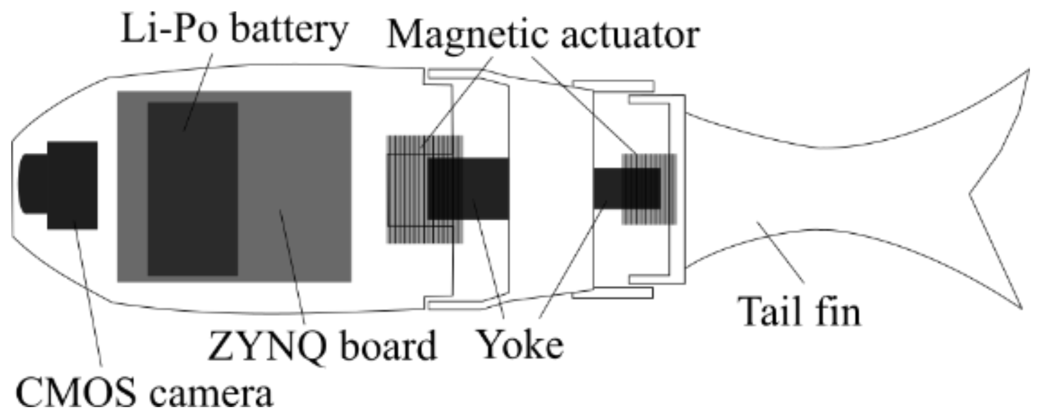
12] can track fish without them being aware of it. The specifications of this small robotic fish are listed in Table 1 and the schematics of its internal structure are shown in Figure 1. 
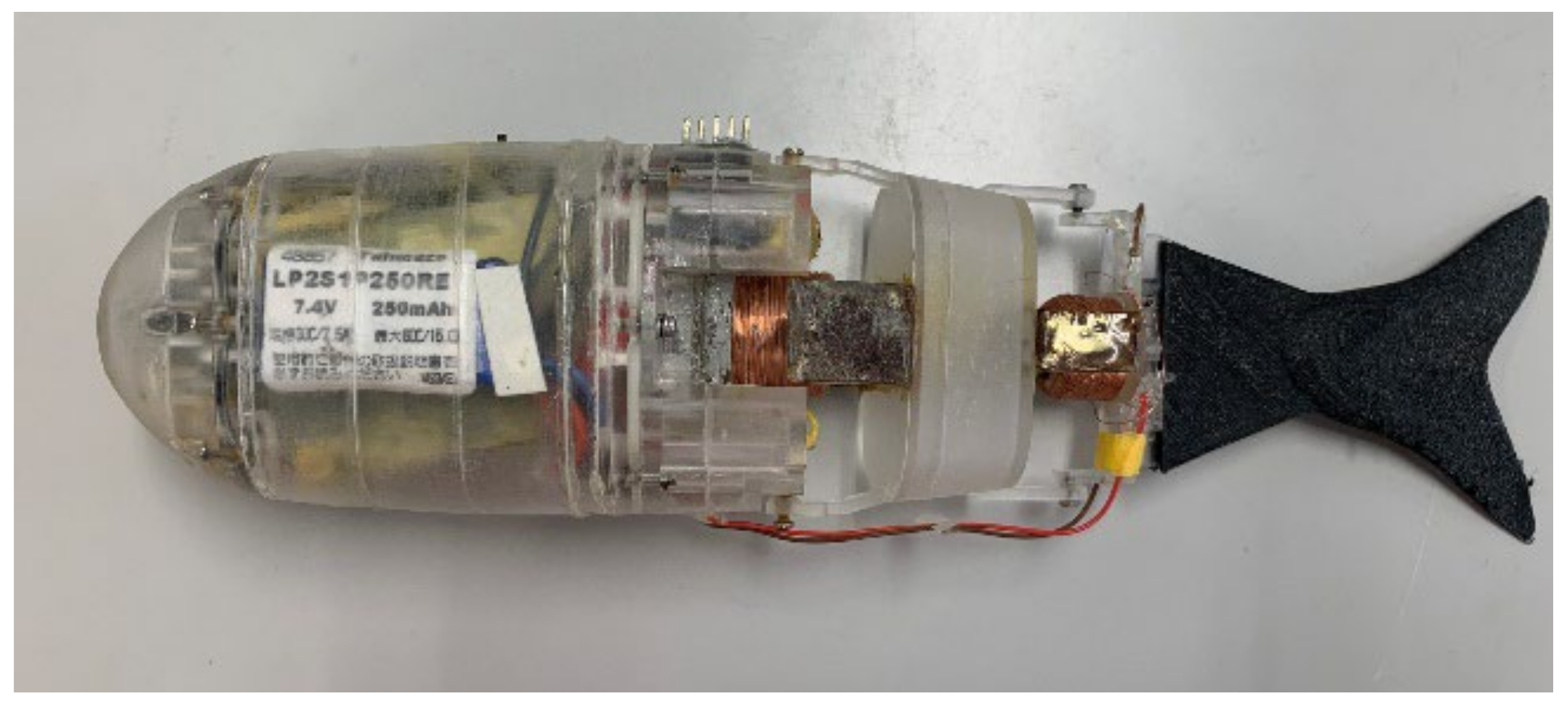
Figure 2 shows a photograph of the side view of the robot [12]. The COMET consists of parts that are cut from acrylic resin and possess two joints. In addition, magnetic actuators consisting of a neodymium magnet and a coil were attached to these joints. COMET is equipped with a 2-cell 7.4 V, 250 mAh lithium polymer battery as a power source. Power of magnetic actuators is supplied from the battery and the battery voltage is stepped down to 5 V, 3.3 V and 2.8 V and supplied to the control board. The angular velocity of the rolling motion when the COMET swims straight is approximately 120°/s and the angular velocity of the yawing motion is approximately 40°/s.
Archerfish prey upon waterside insects by shooting water at them using gills as a pump [13,14,15]. Therefore, we tried to use robotic fish as alien fish exterminators by imitating the habit of archerfish that shoot prey.
Humans are required to approach within 2 m to spear alien fish. However, we predict that robotic fish can approach target alien fish significantly closer than humans because the alien fish are unaware of the robotic fish.
Therefore, by adding the function of spear shooting, we expect that we can reduce the burden of exterminating alien fish by using robotic fish as an alien fish exterminator. There are studies on the behavior of spears on land; however, there are no previous studies on their behavior in water. Hence, studies on the behavior of spears shot by robotic fish are required to determine the necessary conditions to hit an alien fish with a spear.
Therefore, in this study, we developed a spear shooting mechanism that can be equipped with a small robotic fish COMET developed in an earlier study. Furthermore, we conducted spear shooting experiments in situations where the motion characteristics of a small robotic fish were reproduced and we considered the effect of the robot’s motion on the trajectory of the spear. Based on these results, we determined the conditions for the spears to reach the specified target from the small robotic fish.

2. The Mechanism for Experiments

This chapter discusses the structure of the shooting mechanism and the rotational testing machine.

2.1. Shooting Mechanism

In this study, we addressed the ability to shoot the spear by attaching a shooting mechanism outside of the COMET. 
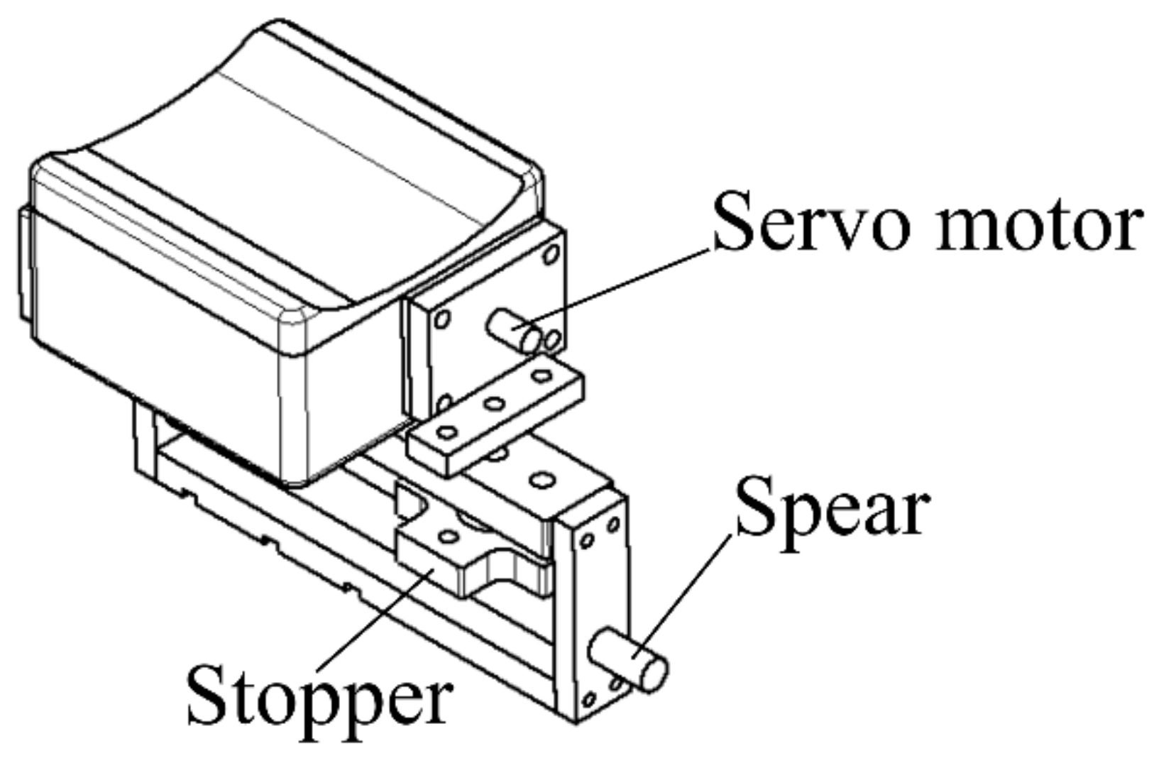
Table 2 shows the specifications of the shooting mechanism and Figure 3 shows the structure of the shooting mechanism.
Table 3 shows the specifications of the spear, Figure 4 shows the structure of the spear and Figure 5 shows an image of the spear. This spear was made of a uniform aluminum alloy cylinder stick (A1050, density: 2700 kg / m 3 ). To identify the location of the spear, the surface of the spear was colored red.
To fix the spear, the spear was pushed against a spring and a stopper was placed in the hole drilled in the spear to hold it in place. By moving the stopper upward with a servo motor, the spear was shot by the force from the spring (spring constant k = 0.37   N / mm ) in the tube.

2.2. Rotation Testing Machine and Experimental Environment

In this study, we developed a rotation testing machine with the ability shown below from (1) to (4) to imitate the movement of the COMET.
(1) The head of the COMET and shooting mechanism can rotate with the shooting direction of the spear as the axis of rotation at an angular velocity of ( ω = 180 ° / s )   and the maximum angle of rotation is ± 22.5 ° to imitate the rolling motion of the COMET.
(2) The head of the COMET and shooting mechanism can rotate about a vertical axis at an angular velocity of ( ω = 160 ° / s ) and the maximum angle of rotation is ± 20 ° to imitate the yawing motion of the COMET.
(3) All of the above movements can be performed under water.
(4) The two movements above can be performed independently.
Figure 6 shows the structure of the rotation-testing machine. We used a DC motor (Maxon 343185) with a gear ratio of 84:1. The 100 P/R rotary encoder (OMROM, E6A-2CW3C) was connected to the edge of the DC motor. A rotary encoder was used for one multiplication. In this case, the angle of the main axis of the motor could be measured with a resolution of 0.043°. This structure is commonly used to reproduce both the rolling and yawing motions.
To reproduce the rolling motion under water, a pulley was fixed to the main spindle of the DC motor, as shown in Figure 6a. The head of the COMET was moved using a rubber pully belt as the transmission mechanism and the reproduced rolling motion of the COMET was operated under water. Similarly, the base was constructed using a 3D printer fixed on the side of the main spindle of the DC motor. The COMET’s head was fixed on the base, as shown in Figure 6b. The base and head of the COMET were rotated together by activating the DC motor to reproduce the yawing motion of the COMET. The rotation angular velocity was obtained from the rotary encoder and an Arduino Uno microcontroller board connected to the main rotation spindle. These were controlled by adjusting the duty ratio of the pulse width modulation of the motor driver (DRV8835) that was connected to the DC motor.
The method for observing the trajectories of the spear that was shot by the shooting mechanism is described below in this section. As shown in Figure 7, shooting experiments of the spear were conducted with the rotation testing machine immersed in an acrylic aquarium 900 mm long, 450 mm wide and 450 mm high (water depth of 225 mm). We filmed the conditions of the experiment from cameras positioned on the top and at the side of the aquarium. The accuracy of the results is dependent on the frame rate; therefore, we filmed at the fastest rate for the camera of 240 fps. The coordinate system was defined with the point of shooting as the origin, the side camera direction as X, the shooting direction as Y and the height direction as Z.
For the graph in this study, the origin was the point of shooting and the value of the XY-coordinates was described as the distance from the origin in mm. The location of the spear was calculated as the center of the red range from the image processing.

3. Shooting Experiments of Spear with Rotation Testing Machine

3.1. Spear Shooting Experiment

First, a shooting experiment under stationary conditions was conducted to determine the influence of the rolling and yawing motions on the trajectory of the spear. We conducted 30 experiments under the same conditions to enable a statistical analysis to be performed. We conducted a t-test five times using the results of 30 shots and 12 shots, which were chosen randomly. When conducting the t-test, the values from Table 4 were compared with the values calculated from 30 experimental results produced in the same way as in Table 4. As a result of the t-test, the population mean of the X-coordinate with a 150 mm Y-coordinate was the same. Therefore, the results of other experiments under different conditions were shown for only 12 results. Figure 8 shows 30 trajectories of the spear shot from the stationary shooting mechanism. Figure 9 shows 12 randomly selected spear trajectories.
The pink lines and angles in Figure 8 and Figure 9 reflect the angles between the robotic fish and the X-axis in Figure 8a and Figure 9a and the XY plane in Figure 8b and Figure 9b. These angles were obtained from the pictures taken immediately before the spear was shot. Angle averages from the 12 sets of pictures were used. The same method for determining angles was adopted for all experiments.
As shown in Figure 8 and Figure 9, the robotic fish shot the spear after tilting relative to the shooting direction by approximately 0.88° towards the positive X-axis and by approximately 6.97° towards the positive Z-axis. The robotic fish does not have a buoyancy control unit; hence, the head of the robotic fish was fixed parallel to the ground (XY plane). However, the spear was allowed to tilt in the directions of the X- and Z-axes.
Next, to determine the influence of the rolling motion on the shot, we conducted an experiment with the rotation testing machine. The head of the robotic fish with the shooting mechanism was rotated with the same rotation angular velocity as the robotic fish. Figure 10 and Figure 11 show the trajectories of the spear shot 12 times from the rotating mechanism. It should be noted that rolling to the left (RL) and rolling to the right (RR) mean counterclockwise or clockwise rotation, respectively, by looking in the shooting direction.
As shown in Figure 10 and Figure 11, when the spear was shot with RL, the robotic fish shot the spear after tilting by approximately 7.9° towards the positive X-axis and by approximately 6.63° towards the positive Z-axis. When the spear was shot with RR, the robotic fish shot the spear after tilting by approximately 1.3° towards the positive X-axis and by approximately 3.88° towards the positive Z-axis. The results of these experiments indicate that the rolling motion of the robotic fish does not affect the trajectories of the spear significantly.
To determine the influence of the yawing motion on the shot, we conducted experiments with the rotation testing machine. The head of the robotic fish with the shooting mechanism of the spear rotated at the same rotation angular velocity of the yawing motion that occurs when the robotic fish swims. Yawing to the left (YL) and yawing to the right (YR) are defined as rotating counterclockwise and clockwise, respectively, by looking down on the robotic fish.
Figure 12 and Figure 13 show the trajectories of the spear shot with the yawing motion. As these figures show, when the spear was shot with YL, the robotic fish shot the spear after tilting by approximately 0.6° towards the positive X-axis and by approximately 6.91° towards the positive Z-axis. When the spear was shot with YR, the robotic fish shot the spear after tilting by approximately 2.7° towards the positive X-axis and by approximately 2.84° towards the positive Z-axis. As a result of these experiments, we deduced that regardless of the yaw direction, the yawing motion of the robotic fish narrowed down the area that the shot spear reached.

3.2. Distribution of Shot Spear Trajectories

Using the data of trajectories shown in the last section, we investigated the trends of the spear trajectories. According to previous studies [12], the robotic fish can track a goldfish by approaching within 100 mm to 200 mm. Therefore, in this study, we assumed that the shooting range (Y-axis) would be from 150 mm to 200 mm.
First, we focused on the X-coordinates with Y-coordinates set to 150 mm and calculated the standard deviation and mean. We used data from the 12 shots shown in Figure 9 to calculate these values. It is noted that the coordinates that could be obtained from pictures from the cameras are discretized so that we obtain the X-coordinate by connecting two points before and after the 150 mm Y-coordinates. Therefore, we applied linear interpolation to obtain the values. In addition, if there are some missing data near the 150 mm Y-coordinates, we approximated by the power function and obtained data for the X-coordinates. We applied a t-test to trajectories between the standard condition and motion condition by using the standard deviation and mean obtained from the above method and investigated whether they have differences in population mean. By applying the same method as above, we assessed the distance from 150 mm to 200 mm in 10 mm increments.
Table 4, Table 5, Table 6, Table 7, Table 8 and Table 9 show the standard deviation and mean of the X-coordinate for each condition. ‘Equal’ means that the data population mean judging from the t-test are similar and ‘Different’ means they are not.
From Table 4, Table 5, Table 6, Table 7, Table 8 and Table 9, the results of the t-test show that the population means of the X-coordinates of the spear shot under a yawing motion differ from those of the standard condition as the Y-coordinate increases. However, the population means under a rolling motion may be different or similar. This means that the rolling motion did not improve the accuracy of the trajectories of the spear compared with the standard condition. Considering these facts, it was inferred that the yawing motion has the potential to improve the accuracy of hitting the target.
The trajectories of the spear were estimated with a probability density function by using a kernel density estimation to research the tendencies of trajectories of the spear shot under different movements that occur in robotic fish. Kernel density estimation is a method of estimating the probability density function of random variables in statistics and the Gaussian function was adopted for kernel density estimation in this study. In addition, the value calculated using Scott’s rule was used for the bandwidth h [16].
Figure 14 shows the probability density function estimated by kernel density estimation.
According to Table 4, there were no differences in the population mean of positions that have 150-mm Y-coordinates between the standard condition and motion conditions, except in the case of rolling to the left. However, from Table 5, Table 6, Table 7, Table 8 and Table 9, the results of the t-test show that the population mean differed from the standard condition under a yawing motion for Y-coordinates ≥ 160 mm. In addition, the population mean was the same between the rolling motion and standard condition for Y-coordinates ≥ 190 mm but differed for the yawing motion. According to Figure 14, we can see that the spear shot under yawing motion behaved in a more stable way than under standard conditions and tended to have a small standard deviation. For the above facts, not only appearance but also statistics showed that the trajectories of the spear differed between the standard condition and yawing motion and the spear shot under yawing motion exhibited better stability. Furthermore, the spear shot under the yawing motion tended to proceed in the opposite direction of the rotating velocity of the shooting mechanism.

3.3. Consideration of Shot Spear Trajectories

The water flow in the aquarium was not the source of any error because the shooting experiments were conducted in a sufficiently large aquarium and there was no effective water flow. One of the sources of error could have been the positioning of the spear just before it was shot. First, in this study, the spear was loaded with a shooting tube for each experiment. The outer diameter of the spear was 3.89 mm and the inner diameter of the tube was 4.00 mm; hence, there was a difference of 0.11 mm. Therefore, it is possible that the posture of the spear differed in each experimental condition. According to the calculation, the spear shot tilted by a maximum of 0.19° towards the shooting direction. The maximum error in the X-axis coordinates was ±0.5 mm for a Y-axis coordinate of 150 mm because of the slope of the spear. However, practically, the fluid (water) exerts a resistance force on the spear that has the potential to shift it in the X-axis direction. Figure 15 shows the forces that are imposed on the spear that have the effect of tilting it in the Y-axis direction under water. Table 10 shows the drag force and lift force acting on the spear from water calculated from Hoerner’s rule [17,18]. α is defined as the angle between the spear and the Y-axis and Table 10 shows the magnitude of the force that was calculated by changing α in 15° increments.
Next, we considered the influence of the initial torque, τ . The initial torque indicates that the torque around the center of gravity of the spear is affected by the spring force, because the spear is tilted in the shooting direction. Figure 16 shows the forces acting on the tilting spear in the shooting tube.
The initial torque was calculated geometrically, based on Figure 16, using Equation (1):
τ = k x l sin θ .
where k is the spring constant; x is the spring compression that was measured in the experiments; l is the distance between the center of gravity of the spear and the point of application of an elastic force, that is, the half-length of the spear; and θ is the angle between the spear and the Y-axis.
Table 11 shows the initial torque calculated by changing θ in 0.05° increments from 0° to 0.15° and maximum angle 0.19° using Equation (1). It should be noted that Table 11 shows only scalar values where the direction of the slope was not considered.
As shown in Table 11, it is expected that the spear would have an angle of more than 0.19° soon after the shot because of the torque exerted by the tilting spear in the tube. As a result, we estimated that the position that the spear finally reaches would scatter along the X-axis because the working force in the X-axis direction was greater in proportion to the angle between the spear and the Y-axis.
Finally, a drag force of approximately 0.04 N was applied to the tip of the spear from the fluid under rolling and yawing motions. The direction of this force was in the opposite direction to the rotation of the robotic fish. This means that the force was always applied in the direction that tried to ensure 0° between the spear and the Y-axis. To follow the above, the rotating motion narrowed down the range of the angle before the shot and obtained a small standard deviation. However, the final positions of the trajectories of the spear shot under a rolling motion are scattered. This is because the turning radius of the rolling motion was smaller than that of the yawing motion, so that the velocity of the tip of the spear was slower for the rolling motion and the drag force from the fluid under rolling was weaker.

4. Behavior Analysis of Spear Shot under Water

To verify the significance of the considerations mentioned above, we created a simulation program that reproduced the behavior of the spear.
The center of gravity position and Euler angles of the spear after the shot from the absolute coordinate system are defined as q :
q = x O y O z O α β γ T .  
The Lagrangian function L is shown below calculated from the kinetic energy T and potential energy U .
L = T U .  
To derive the Lagrangian equation of motion from the Lagrangian function above is shown below:
d d t L q ˙ L q = Q .  
It is noted that Q is the force and torque that worked in the directions of each axis and angle. Q was defined as:
Q = F x   F y   F z   τ α   τ β   τ γ T .  
We investigated the trajectories of the spear after the shot using the above equations by substituting the values.
The position of the spear shown from the absolute coordinate system is x O = x O   y O   z O T . The angular velocity shown in the absolute coordinate system is ω O . There is a relational expression between ω O and the angular velocity of the Euler angle α ˙ = α ˙ β ˙ γ ˙ T , as shown below:
ω O = K C α ˙ .  
K C = 0 S α C α C β 0 C α S α C β 1 0 S β .
However, we defined cos α = C α ,   sin α = S α ,   cos β = C β ,   sin β = S β ,   cos γ = C γ ,   and   sin γ = S γ .
In addition, we used:
a C = R C O T K C α ˙ = R C O T ω O  
where R C O is the rotation transformation matrix that transforms a position on a local coordinate system into an absolute coordinate system, as shown below:
R C O = C α C β C α S β S γ S α C γ C α S β C γ + S α S γ S α C β S α S β S γ + C α C γ S α S β C γ C α S γ S β C β S γ C β C γ .
Therefore, variable α is the angular velocity of the spear on the local coordinate system.
In addition to the position x and angular velocity α C that is defined above, by providing the inertia tensor I C C of the spear represented by the local coordinate system, kinetic energy T was calculated using:
T O = 1 2 m x ˙ O T x ˙ O + a C T I C C a C .
The inertia tensor I C C was expressed by the following equation:
I C C = I c x x c I c x y c I c x z c I c y x c I c y y c I c y z c I c z x c I c z y c I c z z c .
The potential energy U O based on the origin of the absolute system is expressed by the following:
U O = m g T x O ,
where g = g x   g y   g z T is a vector of the gravitational acceleration for each axis direction.
By substituting the kinetic energy T O and the potential energy U O calculated from Equations (10) and (11) into Equation (3), the Lagrangian equation is calculated as
L O = 1 2 m x ˙ O T x ˙ O + 1 2 a T I C C a m g T x O .
Furthermore, after the Lagrangian equation of motion is calculated using the substituted Equation (13) in Equation (4), q was calculated by solving an ordinary differential equation using the Runge–Kutta method.
We simulated trajectories by substituting the initial velocity v O   =   1.6 m/s and initial torque into the program that was made by the above method. We changed the initial angle from −0.19° to 0.19° in 0.019° increments. 
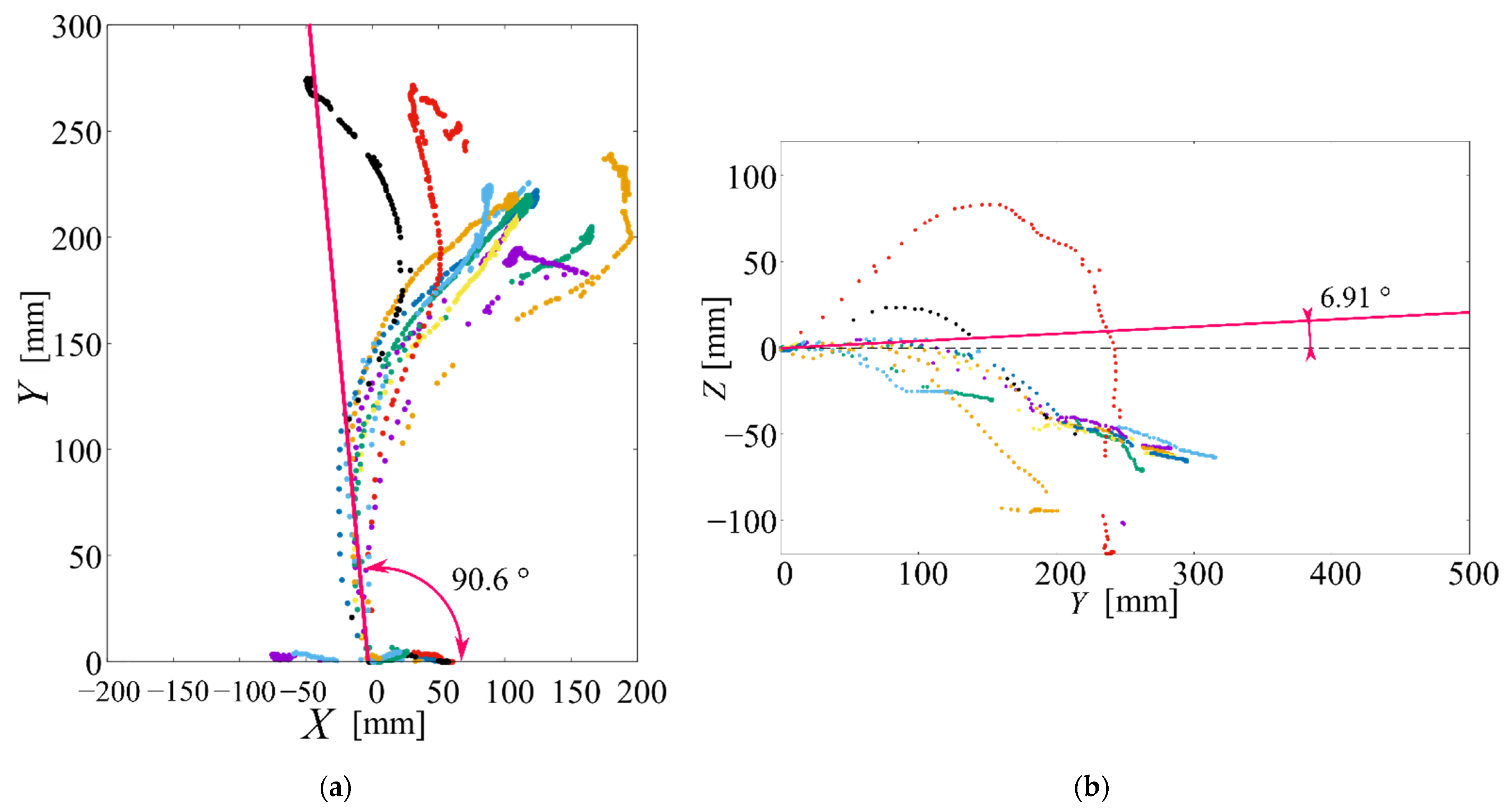
Figure 17 shows the simulation results of the trajectories of the spear shot under a stationary shooting mechanism.
In addition to the above condition, we substituted the initial angular velocity ω O = 160°/s, which has yaw rotation to the right shown from above looking down (Figure 18). This reproduced the yaw motion in the simulation.
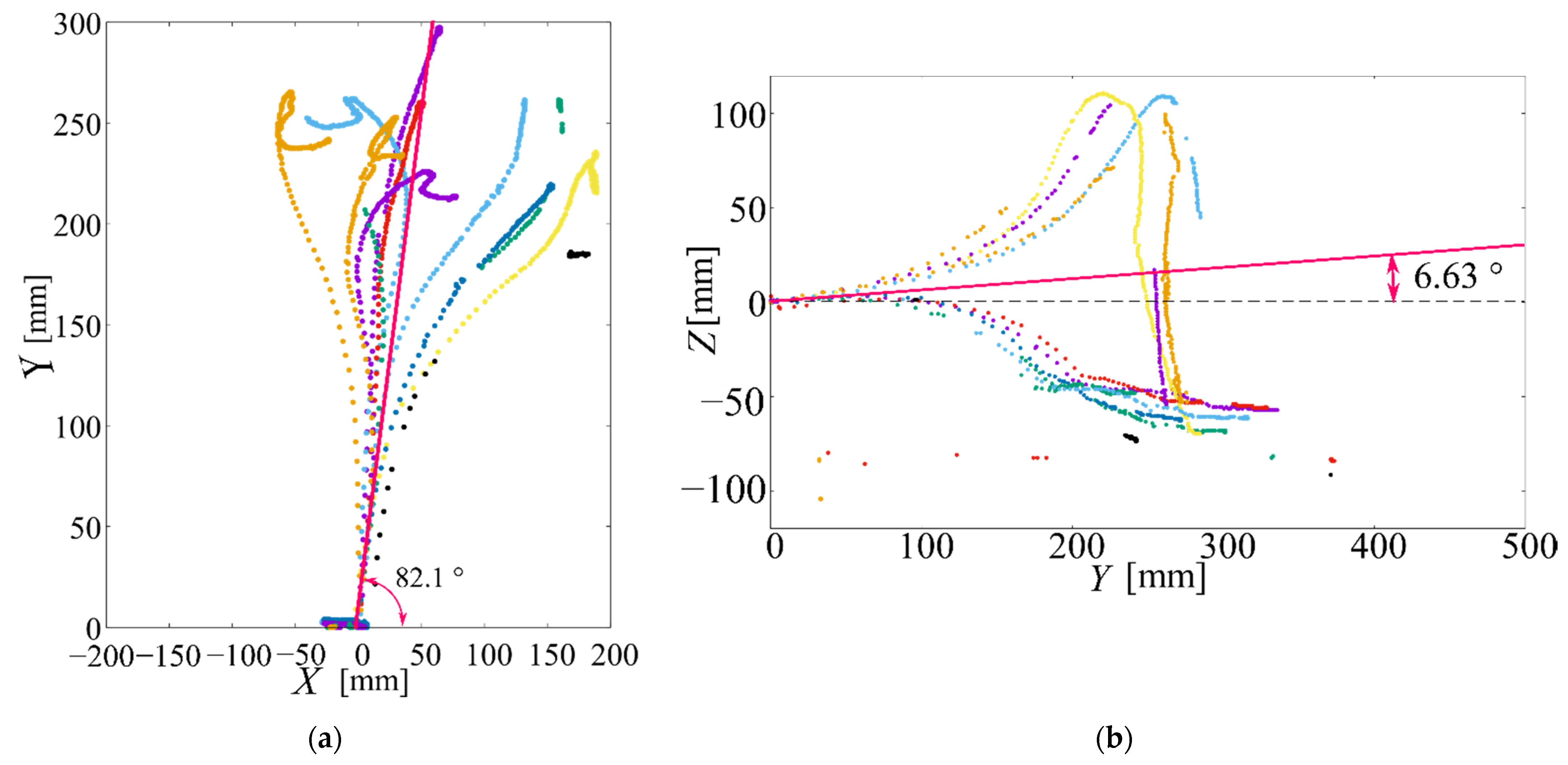
The trajectories of the spears were scattered in the X-axis direction, as shown in Figure 17. This result qualitatively confirms the experimental results. However, comparing Figure 13a with Figure 18, the simulation results show that the spear also proceeded in the positive X-axis direction, while the results of the experiments show that the spear proceeded only in the negative X-axis direction. Furthermore, according to Figure 13a, the spear proceeded in the positive X-axis direction immediately after the shot and then changed direction to the negative X-axis direction. In the simulation, however, the spear proceeded along the Y-axis and then changed direction to the X-axis direction. To explain these results, we also mentioned above that this is because the angle between the spear and shooting direction in the shooting tube under rotating motion was smaller than that under standard conditions. For example, with respect to the simulation conditions, the robotic fish rotated from left to right looking down from above. To follow this rotation, the spear tilted, as shown in Figure 16, when the bottom went right and the tip left. Because of the slope of the spear, the trajectories were concentrated in the direction of negative X-coordinates. It was assumed that the robotic fish shot the spear on 0 X-coordinates in the simulation. However, it is possible for the robotic fish to tilt the spear. According to the above consideration, to rotate Figure 18 around the origin by approximately 2.7° and focus on trajectories only in the negative X-axis direction, the simulation results qualitatively corresponded with the experimental results (Figure 13a). Therefore, the above considerations are reasonable.
For the above reasons, it was inferred that the angle between the spear and shooting direction in the shooting tube affects the trajectories of the spear.

5. Conclusions

In this study, we manufactured a spear shooting mechanism that can be equipped with a robotic fish developed to improve the shooting accuracy of spears and we conducted spear shooting experiments incorporating the motion of yawing and rolling caused by the robotic fish movements because the effects of rolling and yawing motions by robotic fish on the behavior of a spear shot from robotic fish have not been investigated so far. The results showed that the rolling motion did not significantly influence the arrival position of the spear. However, the yawing motion impact was an improvement for the arrival position of the spear. In addition, we conducted a simulation of the spear movement with yawing motion to understand the spear movement. The simulation indicated that the attitude of the spear during loading affected the trajectory of the spear after shooting. In addition, we confirmed that the rotational movement of the robotic fish reduces the range of dispersion in the direction of the X-axis of the trajectory of the spear after shooting owing to a resistance force impacting on the tip of the spear.
In future studies, we will study a method for shooting a spear at a target from a swimming robotic fish.

Author Contributions

Conceptualization, N.K.; methodology, N.K., K.T. and M.O.; software, N.K. and K.T.; investigation, K.T., M.O. and N.K.; writing—original draft preparation, K.T. and N.K.; writing—review and editing, N.K., A.S., M.O. and Y.T.; supervision, Y.T. All authors have read and agreed to the published version of the manuscript.

Funding

This research received no external funding.

Institutional Review Board Statement

Not applicable.

Informed Consent Statement

Not applicable.

Data Availability Statement

Not applicable.

Conflicts of Interest

The authors declare no conflict of interest.

References

  1. Nishizawa, E.; Kurokawa, T.; Yabe, M. Policies and resident’s willingness to pay for restoring the ecosystem damaged by alien fish in Lake Biwa, Japan. Environ. Sci. Policy 2006, 5, 448–456. [Google Scholar] [CrossRef]
  2. Sugiyama, H.; Jinguji, H. Impact and extermination of large mouth bass in irrigation pond. J. Jpn. Soc. Irrig. Drain. Rural. Eng. 2005, 9, 797–800. [Google Scholar]
  3. Nakai, K. Backgrounds and present status of alien species problems among freshwater fishes in Japan: Toward the future management. Ecol. Soc. Jpn. 2000, 2, 171–180. [Google Scholar]
  4. Atsuhiko, I.; Shinsuke, S. Countermeasures against Alien Fishes (Largemouth Bass and Bluegill) in Lake Biwa. Jpn. Fishes Res. Educ. Agency 2010, 29, 79–84. [Google Scholar]
  5. Takemoto, M.; Hosoya, K. Actions on eradication for alien invasive fishes by “Bass busters”. Memoirs Fac. Agric. Kinki Univ. 2012, 45, 241–249. [Google Scholar]
  6. Katano, O. Manual for eradication of harmful alien fish by Fisheries Agency of Japan. Fish Sci. 2012, 4, 773–776. [Google Scholar]
  7. Yoshioka, T.; Uegaki, M.; Ohta, T. The effective strategy for complete removal of alien fish species in Lake Biwa. Fish Sci. 2012, 4, 765–768. [Google Scholar] [CrossRef]
  8. Michalski, T. Multi-Jurisdiction Review of Fisheries Management Strategies for Illegally Introduced Non-native Sport Fish; Ministry of Environment: Nanaimo, BC, Canada, 2007. Available online: http://wikimapia.org/30362464/Ministry-of-Environment (accessed on 9 December 2021).
  9. Takada, Y.; Nakamura, T.; Koyama, K.; Wakisaka, T. Self-position estimation of small fish robot based on visual information from camera. J. Jpn. Inst. Mar. Eng. 2012, 3, 437–443. [Google Scholar] [CrossRef] [Green Version]
  10. Hirata, K.; Takimoto, T.; Tamura, K. Study turning performance of a fish robot. In Proceedings of the First International Symposium on Aqua Bio-Mechanisms, Honolulu, HI, USA, 27–30 August 2000; pp. 287–292. [Google Scholar]
  11. Zhao, Y.; Fukuhara, M.; Usami, T.; Takada, Y. Performance of very small robotic fish equipped with CMOS camera. Robotics 2015, 4, 421–434. [Google Scholar] [CrossRef] [Green Version]
  12. Aritani, T.; Kawasaki, N.; Takada, Y. Small robotic fish with two magnetic actuators for autonomous tracking of a goldfish. J. Aero Aqua Bio-Mech. 2019, 1, 69–74. [Google Scholar] [CrossRef] [Green Version]
  13. Schlegel, T.; Schmid, C.J.; Schuster, S. Animal cognition: How archer fish learn to down rapidly moving targets. Curr. Biol. 2006, 4, 378–383. [Google Scholar] [CrossRef] [Green Version]
  14. Wöhl, S.; Schuster, S. The predictive start of hunting archer fish: A flexible and precise motor pattern performed with the kinematics of an escape C-start. J. Exp. Biol. 2007, 2, 311–324. [Google Scholar] [CrossRef] [PubMed] [Green Version]
  15. Lawrence, M.D. Refraction and the spitting behavior of the archerfish (Toxotes chatareus). Behav. Ecol. Sociobiol. 1977, 2, 169–184. [Google Scholar] [CrossRef]
  16. Scott, D. On optimal and data-based histograms. Biometrika 1979, 3, 605–610. [Google Scholar] [CrossRef]
  17. Hoerner, S.F. Fluid-Dynamic Drag: Practical Information on Aerodynamic drag and Hyrodynamic Resistance, 2nd ed.; Sonoran Nutra LLC: Phoenix, AZ, USA, 1965. [Google Scholar]
  18. Shields, F.D., Jr.; Alonso, C.V. Assessment of flow forces on large wood in rivers. Water Resour. Res. 2012, 4, 1–16. [Google Scholar] [CrossRef]
Figure 1. Structure of COMET.
Robotics 11 00014 g001
Figure 2. Image of COMET.
Robotics 11 00014 g002
Figure 3. Structure of the shooting mechanism.
Robotics 11 00014 g003
Figure 4. Structure of the spear.
Robotics 11 00014 g004
Figure 5. Image of the spear.
Robotics 11 00014 g005
Figure 6. Structure of experimental rotational testing machine: (a) rolling motion; (b) yawing motion.
Robotics 11 00014 g006
Figure 7. Experimental environment for the spear shooting.
Robotics 11 00014 g007
Figure 8. Trajectories of spear shot from stationary shooting mechanism 30 times: (a) top view and (b) side view.
Robotics 11 00014 g008
Figure 9. Trajectories of spear shot from stationary shooting mechanism 12 times: (a) top view and (b) side view.
Robotics 11 00014 g009
Figure 10. Trajectories of spear shot from rotating shooting mechanism rolling to the left (RL): (a) top view and (b) side view.
Robotics 11 00014 g010
Figure 11. Trajectories of spear shot from rotating shooting mechanism rolling to the right (RR): (a) top view and (b) side view.
Robotics 11 00014 g011
Figure 12. Trajectories of spear shot from rotating shooting mechanism yawing to the left (YL): (a) top view and (b) side view.
Robotics 11 00014 g012
Figure 13. Trajectories of spear shot from rotating shooting mechanism yawing to the right (YR): (a) top view and (b) side view.
Robotics 11 00014 g013
Figure 14. Kernel density estimation of the target X-coordinates.
Robotics 11 00014 g014
Figure 15. Definition sketch of velocity and force components.
Robotics 11 00014 g015
Figure 16. Definition sketch of initial torque.
Robotics 11 00014 g016
Figure 17. Simulated trajectory of spear shot from stationary shooting mechanism.
Robotics 11 00014 g017
Figure 18. Simulated trajectory of spear shot from rotating shooting mechanism with YR.
Robotics 11 00014 g018
Table 1. Specifications of the robotic fish COMET.
Length252 mm
Width45 mm
Height60 mm
Mass274 g
Table 2. Specifications of the shooting mechanism.
Length74 mm
Width38 mm
Height48 mm
Mass45 g
Table 3. Specifications of the spear.
Length40.8 mm
Diameter3.89 mm
Mass1.23 g
Table 4. Standard deviation and mean of X-coordinates (Y = 150 mm).
Standard DeviationMean (mm)The Result of t-Test
Standard32.2−1.85-
Roll left (RL)32.932.9Different
Roll right (RR)29.0−14.9Equal
Yaw left (YL)21.224.9Equal
Yaw right (YR)26.9−22.6Equal
Table 5. Standard deviation and mean of X-coordinates (Y = 160 mm).
Standard DeviationMean (mm)The Result of t-Test
Standard39.8−2.08-
RL38.736.6Different
RR34.7−20.3Equal
YL25.738.1Different
YR30.7−33.9Different
Table 6. Standard deviation and mean of X-coordinates (Y = 170 mm).
Standard DeviationMean (mm)The Result of t-Test
Standard47.9−2.8-
RL46.341.2Different
RR42.2−24.3Equal
YL33.155.6Different
YR39.0−53.1Different
Table 7. Standard deviation and mean of X-coordinates (Y = 180 mm).
Standard DeviationMean (mm)The Result of t-Test
Standard57.4−3.71-
RL55.147.8Different
RR49.7−28.3Equal
YL39.871.5Different
YR60.6−80.5Different
Table 8. Standard deviation and mean of X-coordinates (Y = 190 mm).
Standard DeviationMean (mm)The Result of t-Test
Standard70.1−5.92-
RL57.045.0Equal
RR59.7−34.0Equal
YL43.181.8Different
YR53.0−68.3Different
Table 9. Standard deviation and mean of X-coordinates (Y = 200 mm).
Standard DeviationMean (mm)The Result of t-Test
Standard85.1−9.88-
RL63.650.7Equal
RR69.4−37.7Equal
YL45.992.7Different
YR58.8−79.9Different
Table 10. Drag and lift of the spear.
Angle   α Drag [N]Lift [N]
00.0130
0.190.013 4.1 × 10 5
150.0150.010
300.0340.039
450.0760.067
600.130.073
750.180.048
900.200
Table 11. Initial torque of the spear.
Angle   θ [°] Initial   Torque   τ   [ N · m ]
00
0.05 1.1 × 10 4
0.10 2.1 × 10 4
0.15 3.2 × 10 4
0.19 4.1 × 10 4
Publisher’s Note: MDPI stays neutral with regard to jurisdictional claims in published maps and institutional affiliations.

