Use of McKibben Muscle in a Haptic Interface †


Department of Mechanical and Aerospace Engineering, Politecnico di Torino, 10129 Torino, Italy
*
Author to whom correspondence should be addressed.
†
This paper is an extended version of our paper published in Franco, W.; Daniela, M.; Benedictis, C.D.; Ferraresi, C. Dynamic Modeling and Experimental Validation of a Haptic Finger Based on a McKibben Muscle. In Proceedings of the IFToMM Symposium on Mechanism Design for Robotics, Udine, Italy, 11–13 August 2018.
Robotics 2019, 8(1), 13; https://0-doi-org.brum.beds.ac.uk/10.3390/robotics8010013
Submission received: 17 January 2019
/
Revised: 9 February 2019
/
Accepted: 14 February 2019
/
Published: 18 February 2019
(This article belongs to the Special Issue Mechanism Design for Robotics)
Abstract
:One of the most relevant issues in the development of a haptic interface is the choice of the actuators that are devoted to generating the reflection forces. This work has been particularly focused on the employment of the McKibben muscle to this aim. A prototype of one finger has been realized that is intended to be part of a haptic glove, and is based on an articulated mechanism driven by a McKibben muscle. A dynamic model of the finger has been created and validated; then, it has been used to define the control algorithm of the device. Experimental tests highlighted the static and dynamic effectiveness of the device and proved that a McKibben muscle can be appropriately used in such an application.
1. Introduction
Teleoperation consists of the control of a remote machine or device (slave), using an appropriate interface, called a master. The master is haptic if it is able to transmit the sense of touch, for example generating a force reflection to the operator. In general, haptics refers to the study of touch feedback in different applications, including virtual reality (such as for example in medical simulators), gaming, and tele-robots (such as surgical robots or remote manipulators for space exploration).
Among the different haptic devices that are able to generate haptic feedback on different sites of human body, the haptic glove is the most used, because hands play a dominant role in perception and manipulation tasks when grasping virtual objects [1].
When designing a haptic glove, the architecture of the mechanism that is able to transmit the force to the single fingers, as well as the type of sensors and the actuation, must be chosen. Generally, the problem has to be solved for a single finger, and replicated to all the fingers of a hand.
Starting from the performance specifications in terms of degrees of freedom, weight, size, dexterous capabilities, and safety level, multiple mechanisms for the transmission of the reflection force have been developed [2]. In particular, in order to assure the coincidence between the center of the relative rotation of the links of the mechanism and the mean physiological rotational axes of the joints of the fingers, different solutions have been designed. Heo et al. [2] classified five mechanical architectures: serial linkages with rotational joints that are coincident with the physiological rotational axes, linkages with a remote center of rotation, redundant linkages [3], tendon-driven mechanisms, and serial linkages attached to distal segment.
As regards the sensing of the user’s intended motion, the reflection force on the finger and the position of the joints should generally be measured. Heo et al. [2] described some different solutions that have been adopted in the literature. For the measurement of the contact force, force sensing resistors, pneumatic pressure sensors, and strain gauge sensors are frequently used. For the measurement of motion sensing, a bending sensor or a rotary encoder can be used.
To drive the mechanism that is devoted to transmitting the reflection force to the finger, different types of actuators have been used. Conventional electric motors have been efficaciously employed for the availability, reliability, and simplicity of control [2,4]. Due to their intrinsic self-adaptability to the compliance of the biological tissues, non-conventional deformable actuators, such as shape memory alloy actuators [5], may be employed for this purpose. Pneumatic actuators provide some advantages over electric ones in terms of a high power-to-weight ratio, simplicity, safety, low cost, and easy maintenance. However, non-linearities due to air compressibility and actuator friction make it difficult to control pneumatic actuators [1]. Between the pneumatic actuators, the soft actuators present different advantages, due to very high force/weight ratio and low friction [6]. For all these reasons, among the pneumatic actuators, the McKibben pneumatic artificial muscle has been employed in several haptic devices, manipulators, and gloves [7,8,9,10].
The authors developed a prototype of a haptic finger, with a mechanism with one degree of freedom for force feedback actuated by McKibben’s muscle. The device has been studied both as a rehabilitation system [11] and as a haptic system. In particular, a mathematical model of the device was developed, which was validated in a specific condition [12].
In the paper, the prototype of a haptic finger is presented, and the non-linear model developed is described. Therefore, further different validation tests of the model are presented. Finally, several simulations are presented, which are aimed at highlighting the dynamic behavior of the entire device.
2. The Prototype
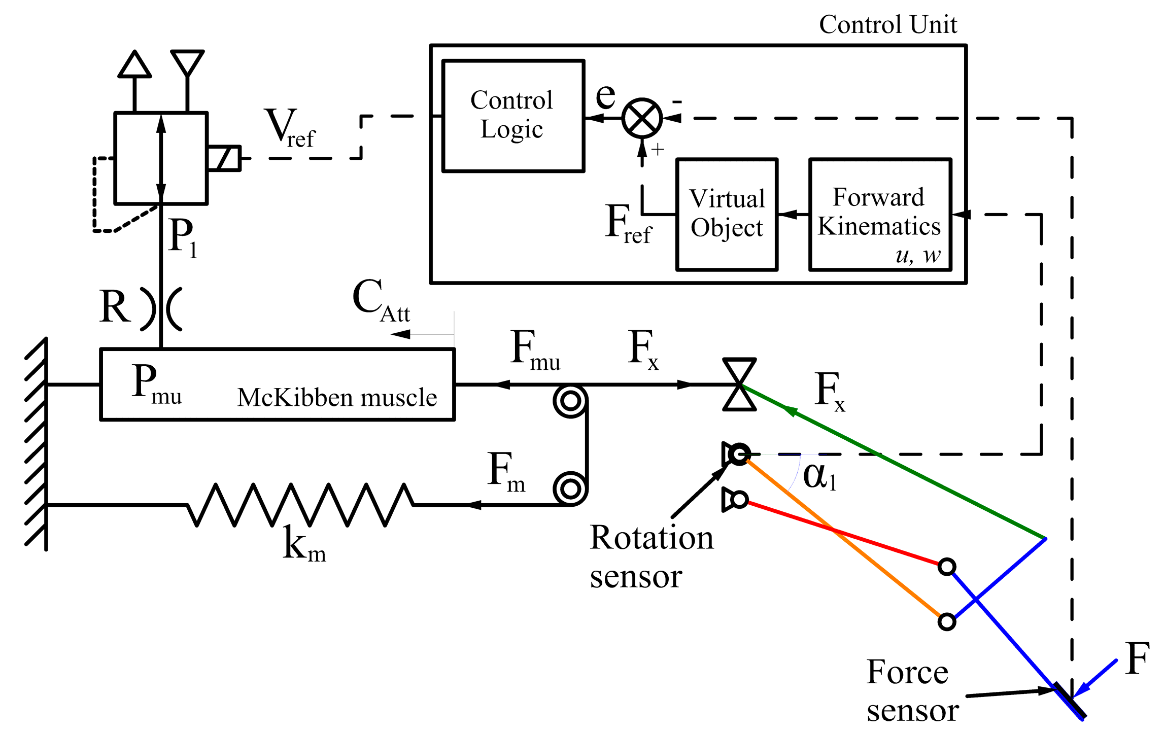
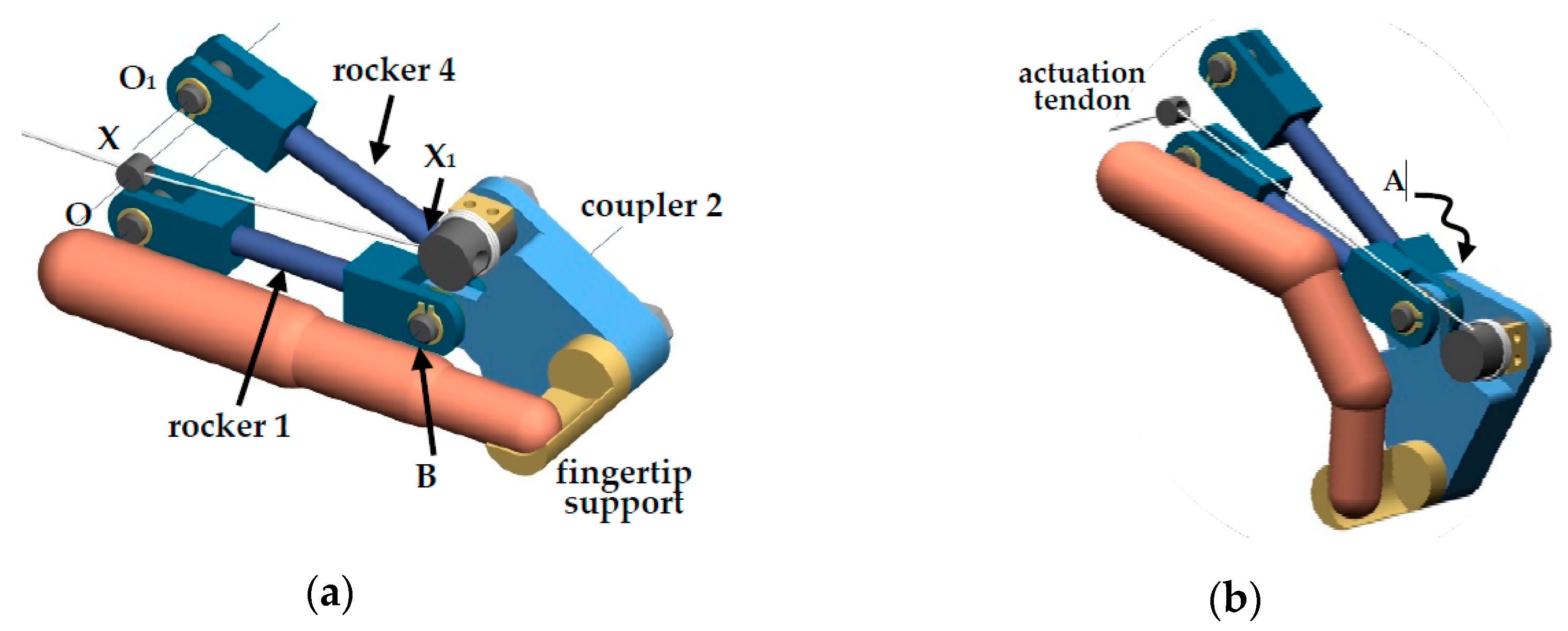
Figure 1 shows the general scheme of the developed device. As regards the mechanism for the transmission of the reflection force on the fingertip, a one degree-of-freedom planar four-bar linkage has been chosen. The operator rests his hand on the fixed frame of the device, while his fingertip is held by a specially designed support integral with the beam force sensor mounted on the coupler of the four-bar mechanism (Figure 2). The operator, manipulating a virtual object or actuating a remote device, moves the finger between the position of maximum extension (Figure 2a) and that of maximum flexion (Figure 2b). For each position of the fingertip imposed by the operator, a corresponding angle α1 of the rocker (Figure 1) is measured by a rotary encoder. The control unit, solving the forward kinematics equations of the mechanism, calculates the position of the fingertip (coordinates u, w in the sagittal plane, Figure 3a). Depending on the geometry and the stiffness of the remote or virtual object, the control unit evaluates the reflection force reference Fref that must be applied to the fingertip. The control unit also calculates the error e between the force reference Fref and the force F measured by the sensor, and provides the command signal for the pressure control proportional valve (FESTO® MPPE-3-1/4-10-010B) Vref, which is used to regulate the upstream pressure p1 of a fluidic resistance R. Regarding the actuation of the feedback force mechanism, a McKibben pneumatic muscle (Shadow Robot Company Ltd., London, UK) has been chosen. The pressure control proportional valve through the fluidic resistance R supplies the muscle and consequently generates a force Fmu that, in parallel with a spring force Fm, pulls a tendon that is connected to the coupler of the four-bar mechanism (Figure 1 and Figure 2).
The dimensional synthesis of the four-bar linkage was carried out by ensuring that the path generated by the coupler point P (fingertip holder) should be included into the natural workspace of a finger, which was calculated by taking into account the dependency among the rotations of each link of the finger (Figure 3a). The selected lengths of the proximal, middle, and distal phalanxes are respectively 4 cm, 2.5 cm, and 2 cm, while the rotation of the distal interphalangeal joint (DIP) joint has been considered to be equal to 2/3 of the proximal interphalangeal joint (PIP) joint rotation [11].
The dimensions of the links of the four-bar mechanism, whose scheme is shown in Figure 3b, are reported in Table 1. The operator’s fingertip is positioned at point P, while the metacarpophalangeal joint (MCP) is coincident with the fixed hinge O. Tendon 5 is connected to coupler 2 in X1; it passes through the low-friction support point X and is pulled by the McKibben muscle.
3. The Dynamic Model
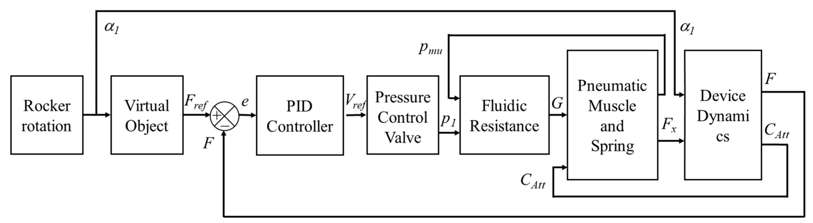
The dynamic model of the haptic finger has been developed according to the logic represented in the block diagram of Figure 5.
Being known the rotation angle of the rocker α1, depending on the position of the operator finger, and the force Fx generated by the McKibben muscle and by a parallel spring, the Device Dynamics block calculates the feedback force F that is applied to the fingertip and the stroke of the McKibben muscle CAtt.
The positioning in the sagittal plane (u, w) of each link of the mechanism can be calculated solving the non-linear system of Equations (1)–(3), thus obtaining ϑ1, ϑ2, and β:
Then, the trajectory of the fingertip in the (u, w) sagittal plane (Figure 3a) is calculated.
The stroke CAtt of the actuator depends on the length of the tendon l5 and the preload stroke of the spring, CAtt1, and is calculated by solving Equation (4):
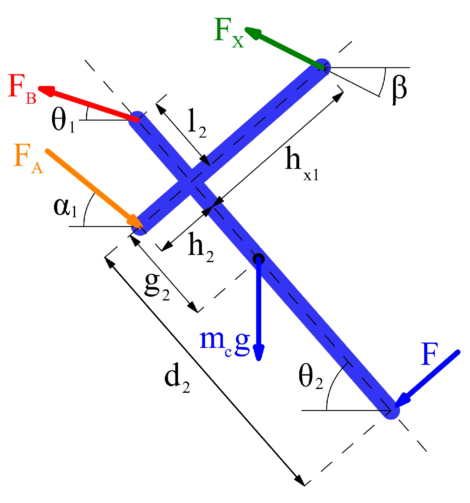
where l5max corresponds to the maximum length XX1 of the tendon (Figure 3b), which occurs at maximum finger flexion. The force F applied to the fingertip is calculated as a function of α1, imposing the equilibrium of the coupler 2 (Figure 6). The direction of F is considered to be perpendicular to the coupler 2 in point P, corresponding to the fingertip support, due to low friction and consequent sliding between the fingertip and the same support. The equivalent mass of the system mc has been considered as centered at point G belonging to the link 2. The static analysis yields the following Equations (5)–(7):
Once the reflection force F has been calculated, and considering that: (i) the force reference Fref is a function of the position (u, w) of the fingertip, depending on the geometry and the mechanical characteristic of the virtual/remote object, (ii) the fingertip position (u, w) is a function of the rocker rotation α1, it is possible to evaluate the force error e:
For the control, a proportional–integral–derivative (PID) algorithm has been adopted:
where KP, KI, and KD are, respectively, the proportional, integral, and derivative gains. After an iterative tuning approach, a simple proportional control came out to be sufficiently accurate and stable for the application, with a proportional coefficient of KP = 0.28.
A second-order transfer function has been used to model the dynamic behavior of the pressure control proportional valve (Pressure Control Valve block):
where KV is the static gain, σn is the natural frequency, and ζ is the damping factor of the valve.
The pneumatic resistance (Fluidic Resistance block) has been modeled according to the ISO 6358 [13]. The mass air flow passing through the resistance can be calculated in sonic or subsonic condition, depending on the ratio between the downstream and upstream pressures:
where P1 is the upstream absolute pressure, Pmu is the downstream absolute pressure, C is the sonic conductance, b is the critical ratio, and ρ0 = 1.18 kg/m3 is the air density in normal conditions. The C and b parameters are reported in Table 1.
Since R = 287.2 J/(kgK) is the air constant, and T is the absolute air temperature, assuming the variation of the internal volume V of the pneumatic muscle as negligible, the time derivative of the absolute internal pressure of the muscle for an isothermal transformation can be expressed as:
with the actual length l and the radius r of the actuator given by:
where, for the employed McKibben muscle (with a 20 mm diameter), Catt is the stroke of the pneumatic muscle, l0 is the initial preloaded length, and nt is the number of turns of the fibers, whose length h is 178 mm.
The internal relative pressure of the muscle pmu can be calculated integrating Equation (12). In order to estimate the force exerted by the pneumatic actuator as a function of the internal pressure pmu, a model of the McKibben muscle must be implemented. Various approaches have been proposed in the literature [14]. Ideal simple models consider only the kinematic relationship between the braided sheath and the inner tube, but unfortunately, they suffer when comparing theoretical and experimental results [15]. To overcome this issue, different models that account for the elastic energy that is stored in the bladder were developed based on the principle of virtual work [16,17,18]. Another approach to derive an analytical expression of the actuation force consists of writing balance equations of a free body diagram of the muscle [15]. Among these types of models, Ferraresi et al. [19] developed and validated a McKibben model, which is able to take into account the effects of the thickness and elasticity of the inner tube. Due to a good compromise between the simplicity and accurate numerical results, the latter model was used to calculate the force exerted by the muscle as a function of the internal pressure of the actuator [19]:
where ri and li are the initial radius and length of the muscle at rest, respectively, si is the initial thickness of the inner chamber, and E is the Young modulus of the chamber.
Finally, the force Fx is directly connected to the force exerted by the muscle Fmu and the spring Fm by the following relations:
where km is the spring constant, and Fm0 is its preload.
4. Experimental Validation of the Model
In order to verify the capability of the device to generate correct force feedback on the fingertip and validate the model, several experimental tests have been performed on the prototype presented in Section 2.
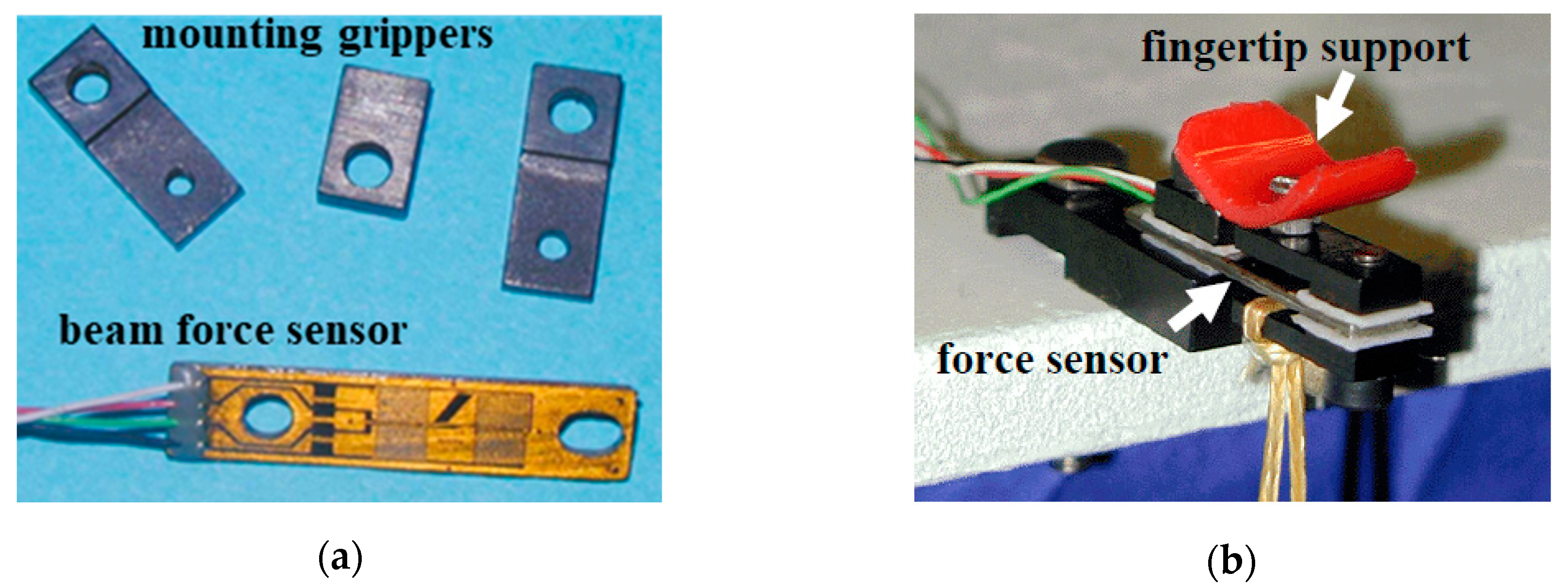
The angular rotation of the rocker 4 (Figure 3b) has been measured by a rotational encoder (BDK series, 1024 pulses, Baumer electric, Frauenfeld, Switzerland), which was processed and acquired by the incremental encoder interface board dSPACE® DS3002. The measurement of the force applied to the fingertip was made through a planar beam resistive sensor (Futek FR1020, capacity 89 N, combined error 0.25% rated output, Irvine, CA, USA) conditioned by a full bridge strain gauge module Meco, model MecoStrain. The acquisition of the force sensor signal was provided by a dSPACE® Multi-Channel A/D Board DS2002. The force sensor is mounted on the coupler by special grasping (Figure 7a). The fingertip support has been made by low-friction plastic material, as shown in Figure 7b, to ensure that the exchanged force can be considered perpendicular to the sensor itself.
The control algorithm was implemented in MATLAB-Simulink® environment, dSpace Control Desk. The command signal of the pressure control proportional valve Vref was generated by a dSPACE® D/A board DS2101.
Figure 8a shows an image of the entire experimental setup during the static experimental tests.
In order to evaluate the dynamic performance of the haptic interface, several experimental tests were conducted. An operator, after positioning his hand on the device with a fully extended index finger, as shown in Figure 4b, is invited to freely perform flexions and extensions of the index finger (Figure 8b), as if he were virtually manipulating an object. The virtual object that was chosen for the experimental tests has a constant stiffness Kobj, so that the feedback force is proportional to the rotation of the rocker α1 according to the equation Fref = Kobj Δα1. During the manipulation, both the angular rotation of the rocker α1, which is freely imposed by the operator, and the reflection force generated on the fingertip by the haptic device were acquired. In all of the tests, a purely proportional control (KP = 0.28 V/N) was implemented, while the stiffness of the virtual object Kobj has been changed in the different tests, and fixed respectively equal to 8 N/rad, 10 N/rad, 20 N/rad, 30 N/rad, 40 N/rad, and 50 N/rad. Then, each test is characterized both by different temporal rotations of the rocker α1 = α1(t) imposed by the operator, and by different stiffness Kobj assigned to the virtual object.
In order to validate the model, simulations were performed by imposing, as an input, the same rotation law of rocker α1 = α1(t) recorded in each experimental test, and calculating the reflection force generated by the system with the same control (purely proportional control with KP = 0.28 V/N), and with same stiffness of the virtual object Kobj.
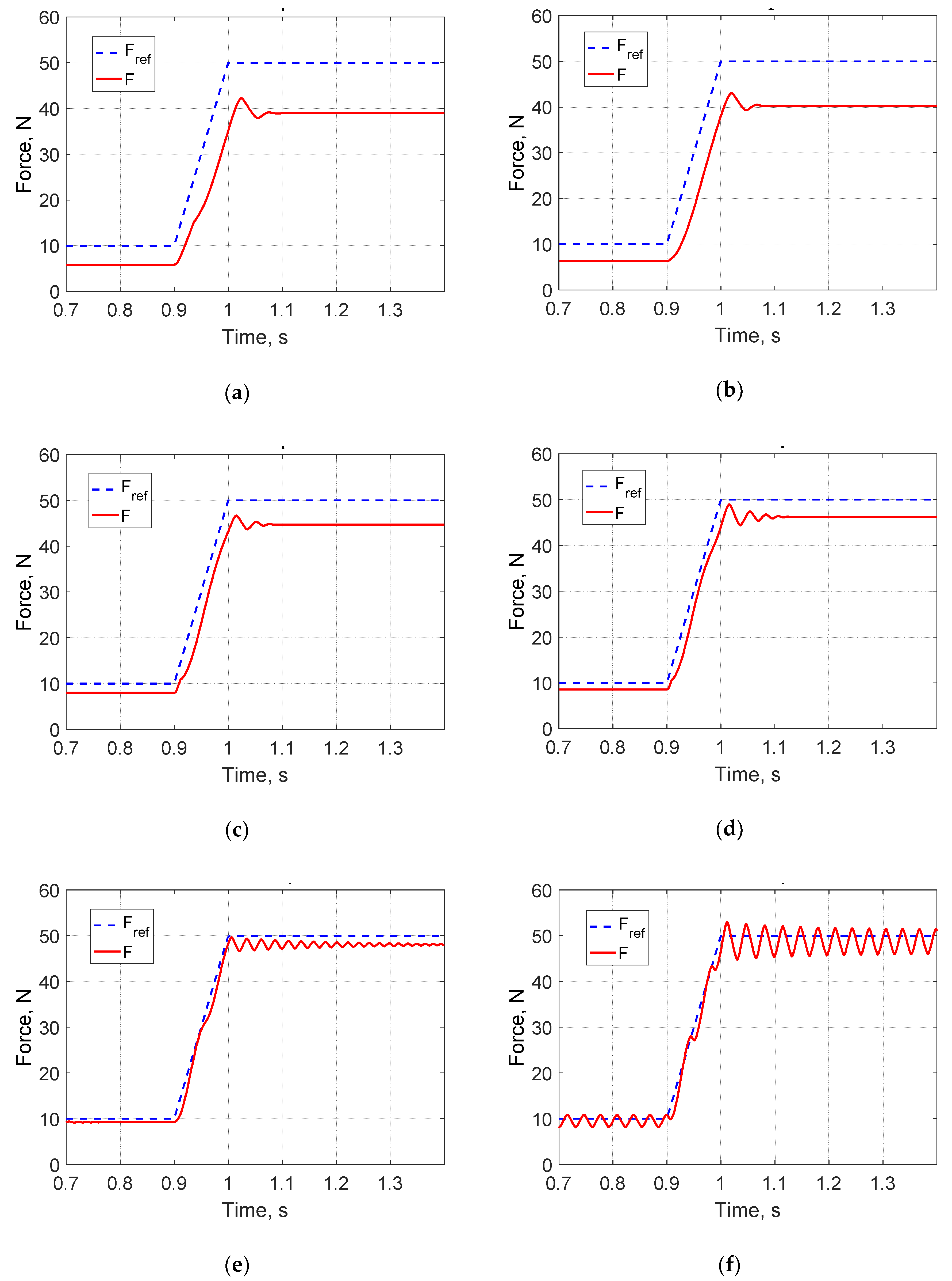
Figure 9 shows the experimental results obtained in the different tests described above, compared with the results of the simulation conducted under the same conditions. The figures show the trends of the experimental and simulated feedback force as a function of time, for different stiffnesses of the object, between 8 N/rad and 50 N/rad.
The most relevant differences between the simulated and the experimental results occurred for more rigid virtual objects, in cases where the operator imposed low-rocker rotation values (low reaction forces) and quickly reversed the direction of rotation.
Nevertheless, the model highlights the ability to predict with good accuracy the trend of the force generated by the device in dynamic conditions.
Based on these results, the model was considered validated and sufficiently reliable to predict the dynamic performance of the device, even under conditions different from those tested. This analysis is presented and discussed in the next section.
5. Dynamic Assessment of the Device
The validated model was used to evaluate the dynamic performance of the device. A first series of simulations concerned the study of the response to step input, for different proportional gain KP values of the pure proportional control (Figure 10). Due to pure proportional control, a steady state error is observed. As expected, when increasing the proportional gain KP, the steady-state error decreases, but for proportional gain values close to 2 V/N, the system tends to instability, and in fact becomes unstable for KP values equal to 3 V/N.
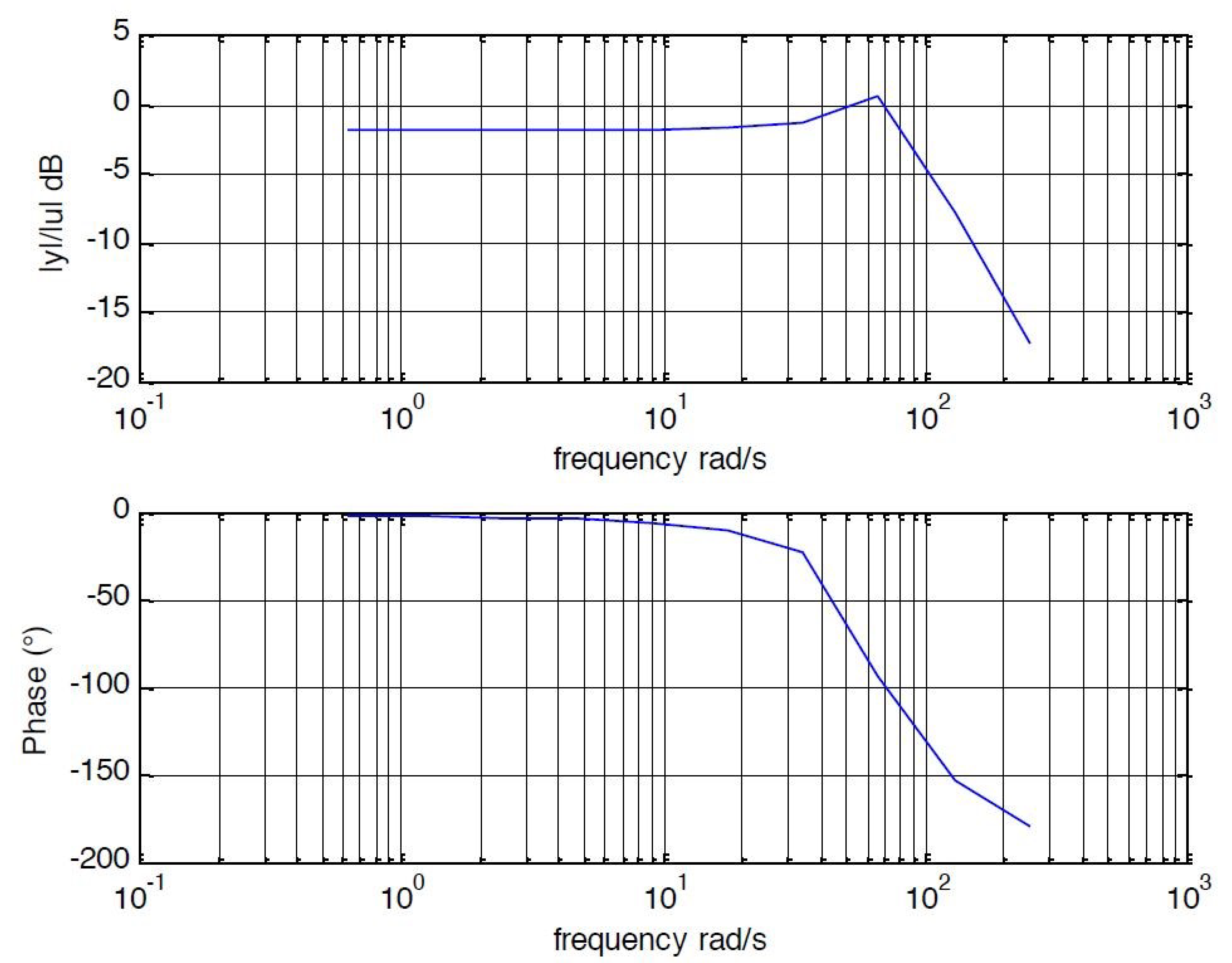
The bandwidth of the device was also estimated using the dynamic model, again with a purely proportional control. Figure 11 shows the Bode diagram of the system, whose behavior has been simulated under nominal conditions (KP = 0.7 V/N). We estimated a bandwidth close to 80 rad/s, which is certainly compatible with many haptic applications.
6. Conclusions
A novel haptic device, which was conceived as a finger for a haptic glove, has been developed and tested. The device is based on a four-bar mechanism, and is actuated by a McKibben muscle. The work has been particularly focused on the employment of such a kind of actuator in haptic applications.
A prototype has been realized and analytically modeled. The model, which was experimentally validated, proved to be able to predict with good accuracy the behavior of the system, and was used both to define the control algorithm and assess the static and dynamic performance of the device.
Experimental tests on the prototype highlighted its effectiveness in applications requiring good haptic sensitivity, confirming that the McKibben muscle can provide relevant advantages when used in these kinds of applications.
Future work will be focused first on the improvement of the control, in particular introducing an integral gain in order to achieve zero steady-state error, and then on the optimization of the finger’s mechanical structure, with the aim of realizing a full haptic glove.
Author Contributions
Conceptualization, W.F. and C.F.; methodology, D.M. and C.D.B.; software, W.F. and C.D.B.; validation, C.F. and D.M.; writing—original draft preparation, W.F.; writing—review and editing, C.D.B.; visualization, D.M.; supervision, C.F.
Funding
This research has not received external funding.
Conflicts of Interest
The authors declare no conflict of interest.
References
- Uddin, M.W.; Zhang, X.; Wang, D. A pneumatic-driven haptic glove with force and tactile feedback. In Proceedings of the 2016 International Conference on Virtual Reality and Visualization (ICVRV2016), Hangzhou, China, 24–26 September 2016; pp. 304–311. [Google Scholar]
- Heo, P.; Gu, G.M.; Lee, S.; Rhee, K.; Kim, J. Current hand exoskeleton technologies for rehabilitation and assistive engineering. Int. J. Precis. Eng. Manuf. 2012, 13, 807–824. [Google Scholar] [CrossRef]
- Malvezzi, M.; Valigi, M.C.; Salvietti, G.; Iqbal, Z.; Hussain, I.; Prattichizzo, D. Design Criteria for Wearable Robotic Extra–Fingers with Underactuated Modular Structure. In Proceedings of the 2nd IFToMM ITALY Conference, Cassino, Italy, 29–30 November 2018; pp. 509–517. [Google Scholar]
- Gerding, E.C.; Carbone, G.; Cafolla, D.; Russo, M.; Ceccarelli, M.; Rink, S.; Corves, B. Design and Testing of a Finger Exoskeleton Prototype. In Proceedings of the 2nd IFToMM ITALY Conference, Cassino, Italy, 29–30 November 2018; pp. 342–349. [Google Scholar]
- Maffiodo, D.; Raparelli, T. Three-Fingered Gripper with Flexure Hinges Actuated by Shape Memory Alloy Wires. Int. J. Autom. Technol. 2017, 11, 355–360. [Google Scholar] [CrossRef] [Green Version]
- Ferraresi, C.; Franco, W.; Quaglia, G. A novel bi-directional deformable fluid actuator. J. Mechan. Eng. Sci. 2014, 228, 2799–2809. [Google Scholar] [CrossRef] [Green Version]
- Sun, Z.; Bao, G.; Yang, Q.; Wang, Z. Design of a Novel Force Feedback Dataglove Based on Pneumatic Artificial Muscles. In Proceedings of the International Conference on Mechatronics and Automation, Luoyang, China, 25–28 June 2006; pp. 968–972. [Google Scholar]
- Li, H.; Kawashima, K.; Todano, K.; Ganguly, S.; Nakano, S. Achieving Haptic Perception in Forceps’ Manipulator Using Pneumatic Artificial Muscle. IEEE/ASME Trans. Mechatron. 2013, 18, 74–85. [Google Scholar] [CrossRef]
- Moon, K.; Ryu, D.; Chun, C.; Lee, Y.; Kang, S.; Park, M. Development of a Slim Haptic Glove Using McKibben Artificial Muscles. In Proceedings of the SICE-ICASE International Joint Conference, Bexco, Busan, Korea, 18–21 October 2006; pp. 204–208. [Google Scholar]
- Egawa, M.; Watanabe, T.; Nakamura, T. Development of a Wearable Haptic Device with Pneumatic Artificial Muscles and MR brake. In Proceedings of the IEEE Virtual Reality (VR), Arles, France, 23–27 March 2015; pp. 173–174. [Google Scholar]
- De Benedictis, C.; Ferraresi, C.; Franco, W.; Maffiodo, D. Hand rehabilitation device actuated by a pneumatic muscle. In Proceedings of the 27th International Conference on Robotics in Alpe-Adria-Danube Region (RAAD 2018), Patras, Greece, 6–8 June 2018; pp. 102–111. [Google Scholar]
- Franco, W.; Maffiodo, D.; De Benedictis, C.; Ferraresi, C. Dynamic modeling and experimental validation of a haptic finger based on a McKibben muscle. In Proceedings of the 4th IFToMM Symposium on Mechanism Design for Robotics, Udine, Italy, 11–13 September 2018; pp. 251–259. [Google Scholar]
- Ferraresi, C.; Sorli, G. Modelling of pneumatic systems. Fluid Apparecchiature Idraul. Pneum. 1993, 346, 48–54. [Google Scholar]
- Tondu, B. Modelling of McKibben artificial muscle: A review. J. Intell. Mater. Syst. Struct. 2012, 23, 225–253. [Google Scholar] [CrossRef]
- Kothera, C.S.; Jangid, M.; Sirohi, J.; Wereley, N.M. Experimental characterization and static modeling of McKibben Actuators. J. Mech. Des. 2009, 131, 091010. [Google Scholar] [CrossRef]
- Klute, G.; Hannaford, B. Accounting for Elastic Energy Storage in McKibben Artificial Muscle Actuators. ASME J. Dyn. Syst. Meas. Control 2000, 122, 386–388. [Google Scholar] [CrossRef] [Green Version]
- Tsagarakis, N.; Caldwell, D. Improved Modelling and Assessment of Pneumatic Muscle Actuators. In Proceedings of the IEEE International Conference on Robotics and Automation (ICRA 2000), San Francisco, CA, USA, 24–28 April 2000; pp. 3641–3646. [Google Scholar]
- Sugimoto, Y.; Naniwa, K.; Osuka, K.; Sankai, Y. Static and dynamic properties of McKibben pneumatic actuator for self-stability of legged robot motion. Adv. Robot. 2013, 27, 469–480. [Google Scholar] [CrossRef]
- Ferraresi, C.; Franco, W.; Manuello Bertetto, A. Flexible Pneumatic Actuators: A comparison between the McKibben and the straight fibres muscle. J. Robot. Mechatron. 2001, 13, 56–63. [Google Scholar] [CrossRef]
Figure 1.
Scheme of the device.

Figure 2.
Mechanism for the transmission of the reflection force to the fingertip: (a) Finger at maximum extension; (b) finger at maximum flexion.
Figure 2.
Mechanism for the transmission of the reflection force to the fingertip: (a) Finger at maximum extension; (b) finger at maximum flexion.

Figure 3.
(a) Workspace of a human index fingertip. (b) Sketch of the mechanism (metacarpophalangeal joint, MCP, proximal interphalangeal joint, PIP, and distal interphalangeal joint, DIP).
Figure 3.
(a) Workspace of a human index fingertip. (b) Sketch of the mechanism (metacarpophalangeal joint, MCP, proximal interphalangeal joint, PIP, and distal interphalangeal joint, DIP).

Figure 4.
The prototype of the device. (a) Detail of the four-bar linkage and of the sensors. (b) Positioning of the operator’s finger.
Figure 4.
The prototype of the device. (a) Detail of the four-bar linkage and of the sensors. (b) Positioning of the operator’s finger.

Figure 5.
Block diagram of the dynamic model of the haptic finger.

Figure 6.
The free body diagram of the coupler (represented in the thick blue line).

Figure 7.
Force sensor. (a) The sensor and the mounting gripper. (b) The sensor in static calibration operation.
Figure 7.
Force sensor. (a) The sensor and the mounting gripper. (b) The sensor in static calibration operation.

Figure 8.
(a) Experimental setup. (b) Handling a virtual object.

Figure 9.
Comparison between experimental and simulation results. (a) Kobj = 8 N/rad. (b) Kobj = 10 N/rad. (c) Kobj = 20 N/rad. (d) Kobj = 30 N/rad. (e) Kobj = 40 N/rad. (f) Kobj = 50 N/rad.
Figure 9.
Comparison between experimental and simulation results. (a) Kobj = 8 N/rad. (b) Kobj = 10 N/rad. (c) Kobj = 20 N/rad. (d) Kobj = 30 N/rad. (e) Kobj = 40 N/rad. (f) Kobj = 50 N/rad.

Figure 10.
Model step response. (a) KP = 0.3 V/N. (b) KP = 0.35 V/N. (c) KP = 0.7 V/N. (d) KP = 1 V/N. (e) KP = 2 V/N. (f) K P= 3 V/N.
Figure 10.
Model step response. (a) KP = 0.3 V/N. (b) KP = 0.35 V/N. (c) KP = 0.7 V/N. (d) KP = 1 V/N. (e) KP = 2 V/N. (f) K P= 3 V/N.

Figure 11.
Model frequency response in terms of F/Fref (KP = 0.7 V/N).


Table 1.
Parameters of the model.
| l1 | 55 mm | hx1 | 18 mm | nt | 1.52 |
| l2 | 5 mm | km | 140 N/m | E | 0.95 MPa |
| d2 | 25 mm | Fm0 | 13.93 N | KP | 0.28–3 V/N |
| g2 | 13 mm | CAtt1 | 20 mm | KV | 1 × 10⁵ Pa/V |
| h2 | 7 mm | mc | 55 g | ζ | 1.8 |
| l4 | 63.9 mm | l0 | 162 mm | σn | 140 rad/s |
| l5max | 81.4 mm | li | 110 mm | C | 5.25 10−9 m3 Pa−1s−1 |
| h0 | 15 mm | ri | 10 mm | b | 0.39 |
| hx | 0 mm | si | 0.8 mm | Kobj | 8–50 N/rad |
© 2019 by the authors. Licensee MDPI, Basel, Switzerland. This article is an open access article distributed under the terms and conditions of the Creative Commons Attribution (CC BY) license (http://creativecommons.org/licenses/by/4.0/).
Share and Cite
MDPI and ACS Style
Franco, W.; Maffiodo, D.; De Benedictis, C.; Ferraresi, C. Use of McKibben Muscle in a Haptic Interface. Robotics 2019, 8, 13. https://0-doi-org.brum.beds.ac.uk/10.3390/robotics8010013
AMA Style
Franco W, Maffiodo D, De Benedictis C, Ferraresi C. Use of McKibben Muscle in a Haptic Interface. Robotics. 2019; 8(1):13. https://0-doi-org.brum.beds.ac.uk/10.3390/robotics8010013
Chicago/Turabian StyleFranco, Walter, Daniela Maffiodo, Carlo De Benedictis, and Carlo Ferraresi. 2019. "Use of McKibben Muscle in a Haptic Interface" Robotics 8, no. 1: 13. https://0-doi-org.brum.beds.ac.uk/10.3390/robotics8010013
Note that from the first issue of 2016, this journal uses article numbers instead of page numbers. See further details here.