Article

Differential Pulse Voltammetric Detection of Acetaminophen Using Nickel Phthalocyanine/CeO2-Modified ITO Electrodes

by
Emiliano C. Gomes
1,
Camila L. Ribeiro
1,
Vianney O. Santos, Jr.
2 and
Leonardo G. Paterno
1,*
1
Laboratório de Pesquisa em Polímeros e Nanomateriais, Instituto de Química, Universidade de Brasília, Brasília 70910-900, DF, Brazil
2
Centro de Pesquisas e Análises Tecnológicas (CPT), Agência Nacional do Petróleo, Gás Natural e Biocombustíveis (ANP), Brasília 70830-902, DF, Brazil
*
Author to whom correspondence should be addressed.
Submission received: 15 January 2023 / Revised: 17 February 2023 / Accepted: 20 February 2023 / Published: 23 February 2023
(This article belongs to the Special Issue Voltammperometric Sensors)

Abstract

:
The present contribution reports a novel electrode based on an ITO substrate surface-modified with a nanofilm of nickel tetrasulfonated phthalocyanine (NiTsPc) with cerium oxide nanoparticles (CeO2) for the effective differential pulse voltammetric detection of acetaminophen, which is a contaminant of emerging concern (CEC). The optimized ITO/NiTsPc/CeO2 electrode responds linearly (r2 > 0.99) to acetaminophen in the range of 0.4 to 11.2 µM, with a limit of detection (S/N = 3) of 54.7 nM. This response is reproducible for fourteen consecutive runs (RSD = 10.97%) and insensitive to the presence of interfering CECs (amoxicillin, atenolol, caffeine, diclofenac, ethinyl estradiol, and ibuprofen) at the same concentration. The electrode can be used to detect acetaminophen in tap water, synthetic urine, and pharmaceutical tablets, in which it performs similarly to UV-Vis spectroscopy at a 95% confidence level.

1. Introduction

Acetaminophen (ACP) (N-(4-hydroxyphenyl)ethanamide), paracetamol) is one of the most used drug to relieve pain and treat fevers because of its analgesic and antipyretic actions [1,2]. Since it is produced and consumed in large amounts, it has been found in aquatic streams, including drinking and waste waters, at concentrations ranging from 0.1 to 300 μg L−1, especially in metropolitan areas [3]. Risk assessment studies reveal that at this level, ACP is toxic to the ecosystems and humans and may also exhibit many other environmental harmful effects [4]. ACP, as well as many other chemicals from pharmaceutical products, is currently classified as a contaminant of emerging concern (CEC) [5].
Determination of CEC in water bodies relies on conventional analytical methods, such as chromatography, mass spectrometry, and hyphenated variants thereof [6]. More specifically, ACP can be determined by titration, UV-Vis spectroscopy, capillary electrophoresis, and high performance liquid chromatography (HPLC) [7]. They are indeed standard methods for accurate determination of chemicals and despite their effectiveness, they all depend on large-sized instruments, specialized personnel for preparing and running sample measurements and data interpretation, and are time-consuming. These features hamper faster and on-site monitoring as well as the implementation within routine analyses.
Detection of ACP (and other CEC) employing electrochemical sensors is an alternative, since these devices meet ease-of-use and low-cost requirements as well as allowing for real-time and on-site sensing, usually waiving the need for a specialized operator [8]. In the particular case of ACP, its molecule is quite electroactive within a wide pH range when hydrolysis, hydroxylation, and dimerization reactions can be observed [9]. Consequently, successful electrochemical detection of ACP has been described for a long time. It is worth mentioning that nowadays, electrodes modified with nanomaterials lead this race because of their enlarged surface-to-volume ratio and improved electrocatalytic activity [10].
Among different types of nanomaterials, cerium oxide nanoparticles (CeO2 or nanoceria) are of great interest because of its intriguing surface chemistry, where it occurs an auto regenerative cycle between Ce3+ and Ce4+ states that results in enhanced catalytic activity [11]. Consequently, CeO2 nanoparticles have been immobilized onto inert electrodes to improve their electrocatalytic activity towards ACP oxidation, thus allowing its detection within various matrices. Using electrodes surface-modified with CeO2 nanoparticles, Kusuma et al. performed the voltammetric detection of ACP in water [12], whereas Azeredo et al. performed it in body fluids [13]. Aiming at point-of-care applications, Stanković et al. [14] developed a disposable biosensor using inkjet-printed carbon nanotube electrodes modified with a nanocomposite film of amidase, CeO2, and graphene. For the same purpose, Ponnaiah et al. [15] evaluated the performance of N-doped CeO2/reduced graphene oxide nanocomposites, whereas Sivakumar et al. [16] tested plain CeO2 nanoparticles.
In order to contribute to this research, we have developed a novel electrode based on an ITO substrate surface-modified with a layer-by-layer nanofilm of nickel(II) tetrasulfonated phthalocyanine (NiTsPc) with CeO2 nanoparticles for the differential pulse voltammetric detection of ACP. As a main result, the optimized ITO/NiTsPc/CeO2 electrode displayed a limit of detection (S/N = 3) of 54.7 nM. The success of this new sensing platform is due to two aspects of its supramolecular structure: (i) combination of the electrocatalytic activity of CeO2 and the electronic conductivity of NiTsPc; and (ii) establishment of a direct electrochemical pathway between CeO2 and NiTsPc that restraints both the oxidation of the phthalocyanine ring and the central Ni2+ ion, whose signals are close to that of ACP oxidation. The supramolecular structure of this nanofilm was investigated by UV-Vis and Raman spectroscopies and scanning electron microscopy, whereas its electrochemical behavior was studied by cyclic voltammetry (CV) and electrochemical impedance spectroscopy (EIS). Finally, its electroanalytical performance was evaluated by differential pulse voltammetry (DPV) with standard and pharmaceutical ACP samples dispersed in different matrices, including ultrapure water, tap water, and synthetic urine. Statistical Student’s t-test confirmed that the determination of ACP by DPV employing the optimized electrode was equivalent to UV-Vis spectroscopy at a 95% confidence level.

2. Materials and Methods

2.1. Materials

All chemicals used in the experiments were of analytical grade or better, without undergoing any additional purification procedure. The water employed for the synthesis of CeO2 nanoparticles, substrate/electrode cleaning, and electrochemical measurements was of ultrapure quality (resistivity: 18 MΩ cm), being provided by a Milli-Q Millipore purification system. The nanofilms were deposited onto rectangular (1 mm × 10 mm × 25 mm) substrates made of quartz and indium-doped tin oxide (ITO, sheet resistance: 15 Ω sq). Certified standards of ACP and other CECs (amoxicillin, atenolol, caffeine, diclofenac, ethinyl estradiol, and ibuprofen) as well as materials for film deposition, including NiTsPc, poly(diallyldimethyl ammonium) hydrochloride (PDAC, molecular weight 400,000 g mol−1), and sodium sulfonated polystyrene (PSS, molecular weight 70,000 g mol−1) were all purchased from Sigma-Aldrich (St. Louis, MI, USA).

2.2. Synthesis of CeO2 Nanoparticles

A stock solution of CeCl3.7H2O (1 mM, 200 mL) was prepared in an Erlenmeyer flask by magnetic stirring at ambient temperature (25 °C). After complete dissolution, a NH4OH solution (28%) was added dropwise until the pH of the mixture reached 10. After 1 h of stirring, 6 mL of H2O2 (35%) was added at once and the mixture was left stirring overnight at ambient temperature. The yellowish precipitate of CeO2 nanoparticles formed after this period was isolated by decantation and subsequently washed with ultrapure water. The mixture was centrifuged (8000 rpm, 10 min) and the supernatant was discarded. This process was repeated three times to ensure the removal of unreacted CeCl3 and remaining ions. An aliquot of the precipitated was dried in a vacuum desiccator for structural analyses, whereas the remaining portion was peptized in aqueous HClO4 solution at pH 4 to produce a colloidal suspension of positively-charged CeO2 nanoparticles for film/electrode fabrication and other structural characterizations.

2.3. Film/Electrode Fabrication

Quartz substrates were sequentially cleaned in piranha solution (H2SO4:H2O2, 3:1, v/v) and ammoniacal solution (H2O:NH4OH:H2O2, 5:1:1, v/v). In between, the substrates were copiously rinsed with ultrapure water. ITO substrates were manually rubbed with neutral detergent and put in an ultrasonic bath (80 W) for 20 min. The detergent was washed off with ultrapure water afterwards. Finally, the substrates were immersed in ultrapure water and put in the ultrasound bath for an additional 20 min.
The CeO2 nanoparticles suspension (3 g L−1; pH 4) and NiTsPc solution (1 g L−1; pH 4) were employed in all nanofilm depositions. A HClO4 (pH 4) solution was used for rinsing. Initially, the substrate (quartz and ITO) was primed with a single layer of the cationic PDAC. The substrate was kept immersed into the PDAC solution (1 g L−1; pH 9) for 3 min., rinsed with ultrapure water and blow dried with compressed air. This process renders the substrate surface positively charged, which aids the deposition of the subsequent layers. The deposition of a single NiTsPc/CeO2 bilayer is illustrated in Scheme 1 and consisted of immersing the PDAC-primed substrate first into the anionic NiTsPc for 3 min, followed by rinsing in HClO4 solution with stirring for 20 s and drying with compressed air. After that, the PDAC-primed substrate + NiTsPc layer was immersed into the CeO2 suspension for 3 min, rinsed with HClO4 solution with stirring for 20 s and dried with compressed air. This deposition cycle was repeated to produce multilayered (NiTsPc/CeO2)-n nanofilms, with n varying from 1 to 20. For comparison purposes, two additional nanofilm architectures were produced in the same way, namely (NiTsPc/PDAC)-10 and (PSS/CeO2)-10. Deposition of the nanofilms onto the ITO substrate was delimited to 0.5 cm2 using Scotch tape.

2.4. Structural and Morphological Characterizations

The structure and morphology of the CeO2 nanoparticles were assessed by X-ray diffractometry (D8 Focus Bruker diffractometer (Germany), Cu Kα 1.54 angstroms, increment 0.05°, and velocity 0.5° degrees min−1), transmission electron microscopy (TEM, JEOL JEM-2100 microscope operated at 200 keV (Japan)), electrophoretic light scattering (Malvern Zetasizer ZS90 (UK)), UV-Vis spectroscopy (Varian Cary 5000 spectrophotometer (Agilent, USA), range 200–800 nm with 10 nm s−1 scan rate and 0.5 nm resolution) and Raman spectroscopy (InVia Raman Renishaw (UK) equipped with a 632.8 nm laser, 25 mW; Leica microscope; CCD detector; 50× objective lens, backscattering configuration; 1200-lines/mm grating; resolution 1 cm−1).
Film deposition onto the quartz substrate was monitored ex situ by UV-Vis and Raman spectroscopies, whereas morphology and chemical composition were investigated by scanning electron microscopy and energy-dispersive X-ray spectroscopy (SEM-EDS, JSM—6610 Jeol microscope coupled with the Thermo Scientific NSS spectral imaging probe).

2.5. Electrochemical Measurements

A potentiostat/galvanostat (Metrohm Autolab PGSTAT 204) controlled by the NOVA 1.11 software was employed in all electrochemical experiments (CV, EIS, and DPV). Measurements were conducted at 25 °C under ambient air within a 70 mL glass cell (Metrohm) using a three-electrode arrangement: Ag/AgCl as the reference electrode, Pt wire as the counter electrode, and bare or nanofilm-modified ITO substrate as the working electrode. For EIS experiments, the FRA 2 module was used, with the following measuring conditions: 100 MHz to 0.1 Hz, 10 points per decade, and amplitude of 50 Mv.
Stock solutions (25 mL, 5 mM) of ACP and other CECs [amoxicillin (AMX), atenolol (ATN), caffeine (CAF), ibuprofen (IBPF), diclofenac (DCF), and ethinyl estradiol (EE2)] were prepared first in absolute ethanol. Aliquots (10 µL) were then spiked into the electrochemical cell containing sodium acetate buffer (50 mL, 0.1 M, pH 3). The mixture was homogenized by magnetic stirring prior to each measurement. Optimization of the DPV conditions was investigated with a fixed concentration of ACP (20 μM) in: (i) different pHs, using the Britton–Robinson buffer only; (ii) different electrolyte compositions (0.1 M, pH 3), using sodium sulfate, sodium citrate, acetic acid, sodium acetate, and Britton–Robinson buffer; and (iii) different scan rate, pulse time, and pulse amplitude. The latter investigation was aimed to find the conditions in which the full width at half maximum (W1/2) of the electrochemical signal was the narrowest one. The deposition time was fixed as 120 s followed by a rest time of 30 s before starting the measurements. For the reproducibility test, the electrode was rinsed with the electrolyte between each run and ACP oxidation was measured under the optimized conditions until the current density decreased to 11%, which is the limit established by AOAC recommendations [17].
Determination of ACP in the pharmaceutical tablet was done by DPV and also by UV-Vis spectroscopy. For DPV analysis, the pharmaceutical tablet with a nominal ACP dose of 750 mg (as informed in the package label) was first ground in a mortar. An adequate amount of the powder was then dissolved in 15 mL of absolute ethanol by ultrasonic stirring for 20 min. The solution was transferred to a volumetric flask (25 mL) and the final volume was reached using absolute ethanol. The final concentration of ACP in this solution was estimated as 5 × 10⁻³ M. After that, 50 µL of this solution was added to the electrochemical cell containing 25 mL of 0.1 M sodium acetate, pH 3.0. After measuring this sample, we made successive spikes of standard ACP to reach three concentrations: 5, 10, and 20 µM. A calibration plot was built to estimate the concentration of ACP in the pharmaceutical tablet. For comparison, the concentration of ACP in the pharmaceutical tablet was determined by UV-Vis spectroscopy according to the method described elsewhere [18]. The ground tablet powder (0.1 g) was dissolved in 50 mL of 0.010 M NaOH solution for 15 min in an ultrasonic bath. The solution was then transferred to a volumetric flask (100 mL) and the volume completed with ultrapure water. In the next step, 80 μL of this stock solution was transferred to a 10 mL volumetric flask and the volume was completed with 0.010 M NaOH solution. The UV-Vis spectrum of this solution was registered in the range of 200–350 nm. The conversion of absorbance (at 257 nm) to mg was done with the aid of a calibration plot that was built with the absorbance of four aqueous solutions of standard ACP (3.3, 3.9, 4.6, and 6.6 µM).
Synthetic urine was prepared according to the following composition as reported elsewhere [19]: ultrapure water (50 mL), NaCl (0.146 g), KCl (0.08 g), CaCl2 2H2O (0.056 g), Na2SO4 (0.112 g), KH2PO4 (0.07 g), NH4Cl (0.05 g), urea (1.25 g), and creatinine (0.004 g). Determination of ACP was done by standard addition/recovery tests, in the following ACP concentrations: 1.0, 2.0, 2.4, 2.8, 50, 90, 110, and 130 µM.
Tap water was filtered through a 0.45 µM PTFE syringe membrane and used to prepare the electrolyte (0.1 M sodium acetate, pH 3). After that, aliquots of the standard ACP solution were successively added to the electrolyte prepared in tap water to reach 1 µM, 5 µM, and 50 µM final concentrations and the electrochemical signal was registered. The recovery was then calculated.

3. Results and Discussion

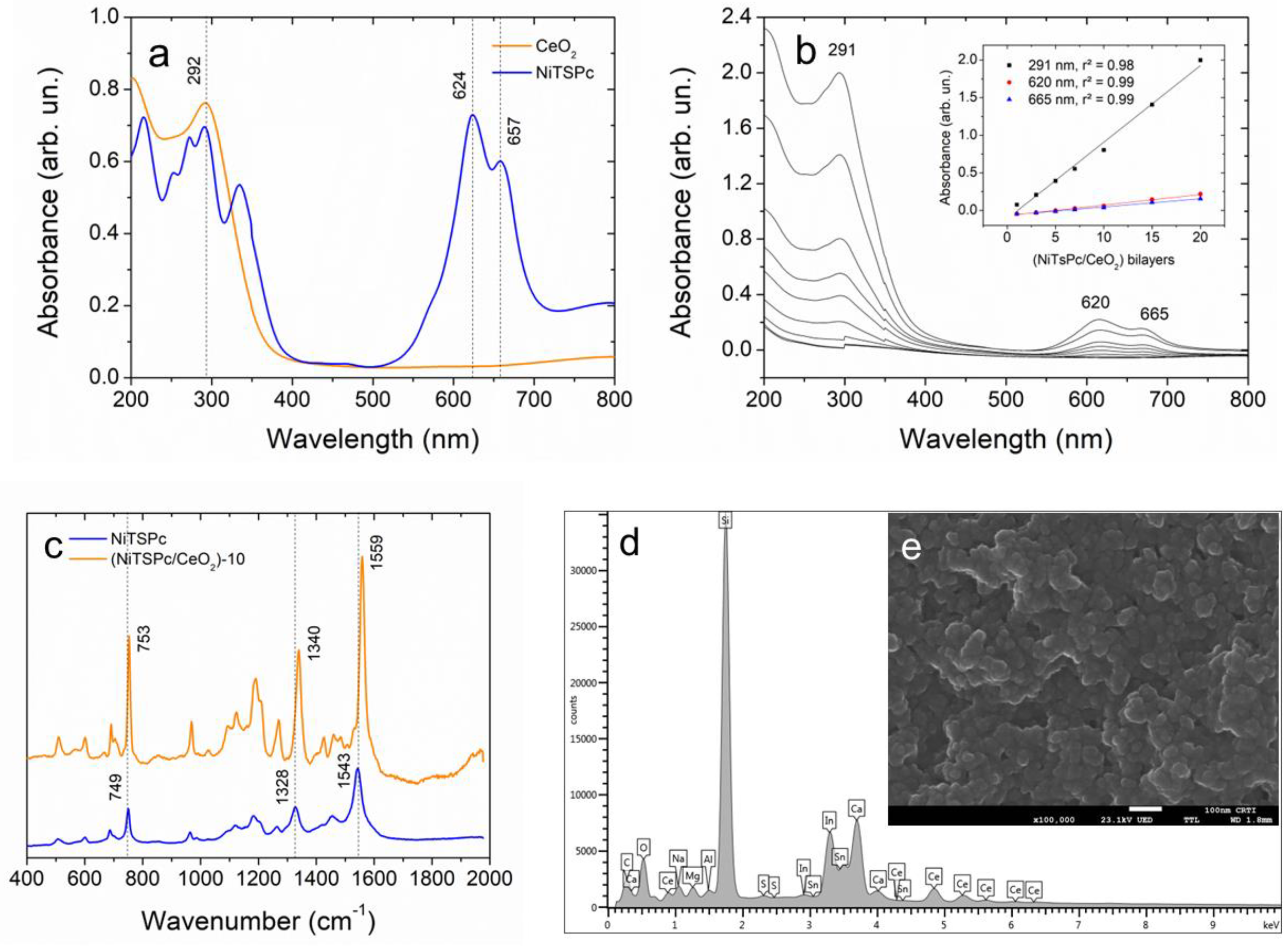
3.1. Structural Characterization of CeO2 Nanoparticles and (NiTsPc/CeO2) Nanofilms

The structural features of the CeO2 nanoparticles were assessed by a set of characterization methods as discussed in detail in the Supplementary Materials along with Figure S1. In brief, they confirmed the identity of the nanoparticles as being CeO2 in agreement with the literature [20,21]. They have a crystalline aspect and spherical shape, with a mean particle size of 2.93 ± 0.02 nm.
Figure 1 reports the structural features of the (NiTsPc/CeO2) nanofilm. As shown in Figure 1a, the UV-Vis spectrum of the suspension of CeO2 nanoparticles had a single peak at 292 nm, which is ascribed to the O2-(2p) → Ce4+(4f) charge-transfer [20]. Meanwhile, the spectrum of NiTsPc was composed by two main absorptions: the Q-band, which is split into two components at 624 nm and 657 nm and assigned to dimeric and monomeric species, respectively; and the Soret band, located at 335 nm [22]. The spectra of the nanofilm adsorbed onto quartz after successive deposition of (NiTsPc/CeO2) bilayers are shown in Figure 1b. They feature a combination of both CeO2 and NiTsPc electronic transitions. In addition, we observed a slight blueshift of the absorption of dimerized species and a redshift of monomeric species, suggesting an interaction between NiTsPc and CeO2. The inset in Figure 1b reveals that those absorptions scaled linearly with the number of (NiTsPc/CeO2) bilayers. In other words, the amounts of NiTsPc and CeO2 were the same in each deposition cycle. This adsorption behavior is typical of an electrostatically driven, layer-by-layer assembly, in which charge overcompensation between oppositely charged materials leads to a self-regulated process [23]. It is worth mentioning that NiTsPc molecules contains four sulfonic groups (please refer to Scheme 1), whereas CeO2 nanoparticles are positively charged in pH 4 (zeta potential: 13.6 ± 1.3 mV). Therefore, electrostatic interaction between these materials is highly expected. Figure 1c provides the Raman spectra of plain NiTsPc and (NiTsPc/CeO2)-10 nanofilms. Three main peaks in the NiTsPc spectrum (in blue) were readily detected: macrocycle breathing (749 cm−1), isoindole N-Ni stretching (1328 cm−1), and C=C, C=N pyrrole stretchings (1543 cm−1) [24]. The same peaks appeared in the spectrum of the (NiTsPc/CeO2)-10 nanofilm although they were all blue shifted over 10 cm−1 for the case of the macrocycle breathing and isoindole N-Ni stretching. These shifts were observed independently of the number of (NiTsPc/CeO2) bilayers, thus reiterating the molecular-level interaction between NiTsPc and CeO2 as already seen by UV-Vis spectroscopy. Indeed, previous studies have described this blueshift in supramolecular systems comprising either NiTsPc or ZnTsPc with iron oxide nanoparticles [24,25]. Finally, as shown in Figure 1d,e, the (NiTsPc/CeO2)-10 nanofilm microstructure was porous, composed of aggregates of CeO2 nanoparticles embedded within an amorphous matrix with the presence of cerium (from CeO2) and silicon, tin, and indium (from the ITO substrate underneath).

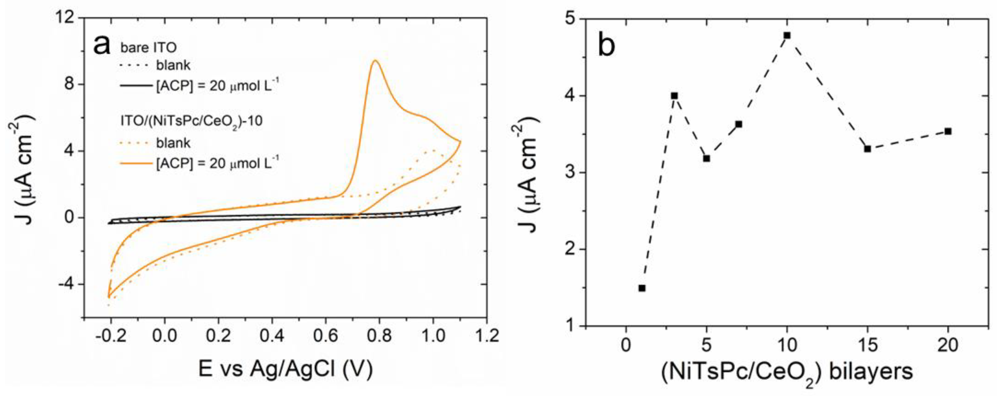
3.2. Electrochemical Behavior of ACP onto ITO/(NiTsPc/CeO2) Electrode

Figure S2 (Supplementary Material) shows the EIS spectra of ferri/ferrocyanide (1 mM) and ACP (20 µM) in sodium acetate buffer 0.1 M and pH 3 using bare ITO and ITO/(NiTsPc/CeO2)-10 as working electrodes. The beneficial role of the nanofilm for the electrode performance was clear in the ferri/ferro spectra (Figure S2a), as the overall impedance was decreased upon deposition of the (NiTsPc/CeO2)-10 nanofilm. More specifically, when the impedance spectra were fitted with the equivalent Randles circuit (inset of Figure S2a), the charge-transfer resistance (Rct) decreased from 370 Ω (bare ITO) to 104 Ω (ITO/(NiTsPc/CeO2)-10). The EIS spectra of ACP, using the same electrodes shown in Figure S2b, exhibited a rather capacitive behavior, which seems to be independent of the presence of the nanofilm. The equivalent circuit in the inset of Figure S2b is a modified version of the Randles circuit, where the Warburg element was replaced by a second capacitor. Among the different circuits, this one provided the best fitting parameters (please refer to Table S1). This capacitive element, Cads, accounts for the adsorption of ACP molecules onto the electrode. Additionally, it can be seen in Figure S2c, a monotonical decrease of Rct with the number of (NiTsPc/CeO2) bilayers, reached a plateau at 10 bilayers. Thereby, it corroborates the role of the nanofilm for the oxidation of ACP and consequent improvement of the electrode performance.
Figure 2 shows cyclic voltammograms of ACP using bare ITO and ITO/(NiTsPc/CeO2)-10 modified ITO electrodes. The current density J is given in µA cm−2. Figure 2a clearly shows the pivotal role of the (NiTsPc/CeO2)-10 nanofilm for the electrochemical oxidation of ACP. Using the modified electrode, ACP oxidation started at +0.65 V and peaked at +0.72 V. On the other hand, bare ITO was unable to oxidize ACP. Figure 2b shows that ACP oxidation current density scales more or less asymptotically with the number of (NiTsPc/CeO2) bilayers, with a maximum being reached at n = 10. This number of bilayers coincides with the minimum Rct reached upon nanofilm deposition, as shown in Figure S2c. Therefore, the ITO/(NiTsPc/CeO2)-10 electrode was selected for the electroanalytical determination of ACP.
Figure 3 reports the electrochemical kinetics of ACP electro-oxidation onto the ITO/(NiTsPc/CeO2)-10 electrode studied by CV. As shown in Figure 3a, voltammograms registered at different scan rates, from 50 mv s−1 to 175 mV s−1, had an anodic peak at +0.72 V, and whose current increased with the scan rate and was assigned to ACP oxidation. A secondary anodic peak was seen at +0.56 V. Its position shifted to higher potentials as the scan rate increased, which is typical of a charge-transfer process and will be discussed in detail later on. Figure 3b shows the linear dependence of the ACP oxidation current on the scan rate. Indeed, it had a correlation coefficient better than that determined between the current and the square root of the scan rate. This result suggests that ACP electro-oxidation is more dependent on adsorption than diffusion, as was already observed on the EIS study (please refer to Figure S2b). Figure 3c shows a Tafel plot, where we can see a linear dependence of the anodic peak potential (Epa) on log J. The respective fitting equation is given by: Ea = 0.406 + 0.209 log J, R2 = 0.997. The slope equals to Equation (1), as follows:
s l o p e = 2.303 R T 1 α F
where, R = 8.31 J K−1 mol−1, T = 298.15 K, and F = 96,500 C mol−1. The value found for α, the charge-transfer coefficient, was 0.72. Subsequently, Figure 3d shows the linear dependence between Epa and the scan rate (ln v), which is given by the following equation: Epa = 0.743 + 0.011 ln v, R2 = 0.997. This one resembles the Laviron equation,
E p a = E 0 + R T 2 α n F l n v  
The slope of the straight line is equal to [RT/2αnF], in which n is the number of transferred electrons. Once α is known, n can be calculated. The value found was 1.61 (~2), which corroborates with a two-electron oxidation process that is usually observed with ACP [9].
In order to understand further the underlying mechanism of the oxidation of ACP at the ITO/(NiTsPc/CeO2)-10 electrode, two other electrode architectures were tested in the same conditions, plain electrolyte and ACP (20 µM). As described in the experimental section, the other two electrode architectures, ITO/(PSS/CeO2)-10 and ITO/(NiTsPc/PDAC)-10, contained CeO2 and NiTsPc assembled separated and with non-electroactive polymers, PSS and PDAC, respectively. As seen in Figure S3a, in plain electrolyte, bare ITO had no electrochemical signal. For ITO/(PSS/CeO2)-10, the voltammogram showed a subtle anodic peak at ~+0.4 V assigned to Ce3+/4+, whereas for ITO/(NiTsPc/PDAC)-10, it showed two anodic peaks at ~+0.76 V and ~+1.0 V, which are ascribed to [TsPc]6−/5− (phtalocyanine ring) and Ni2+/3+ and two cathodic peaks at ~+0.64 V and ~+0.17 V, which were assigned to the respective reverse reactions [26]. Curiously, for ITO/(NiTsPc/CeO2)-10, the voltammogram only showed the anodic peaks (Ce3+/4+ and Ni2+/3+) and with much lower currents. When ACP is present (Figure S3b), the voltammograms for bare ITO and ITO/(PSS/CeO2)-10 were unaltered; for ITO/(NiTsPc/PDAC)-10, the [TsPc]6−/5− signal was somehow mixed with that of ACP oxidation, whereas the Ni2+/3+ peak remained the same. Finally, for ITO/(NiTsPc/CeO2)-10, the voltammogram showed a distinguished peak at +0.78 V due to ACP oxidation, followed by a smaller peak at ~+0.97 V that was assigned to Ni2+/3+.
Owing to its electrocatalytic activity, metallophthalocyanines have been used in different electrochemical applications, such as chemical sensors and O2/CO2 reduction reactions [27,28,29,30]. CeO2 nanoparticles have been employed in photocatalysis [31] and fuel cells [32] for the same reasons. However, electrodes modified with these materials alone were not capable of providing an electrochemical signal for the presence of ACP. The results presented in Figure S3 and detailed above suggest that the NiTsPc/CeO2 interaction is essential for the modified ITO to undertake the oxidation of ACP. The presence of CeO2 inhibits the oxidation of the phthalocyanine ring and Ni2+ to Ni3+ by establishing an alternative path with NiTsPc for the effective electron transfer across the nanofilm. Indeed, the intimate contact between these elements was detected in UV-Vis and Raman spectra, as discussed in Section 3.1, as well as by the charge-transfer event between them, which was seen as an anodic peak at +0.56 V (shown in Figure 3a). Additionally, since ITO/(PSS/CeO2)-10 did not respond to ACP, it is concluded that the electrocatalytic activity of CeO2 nanoparticles was not enough to provide an electrochemical signal for ACP. It is also necessary for the presence of a second electrical conducting phase to enable electron conduction paths across the electrode.

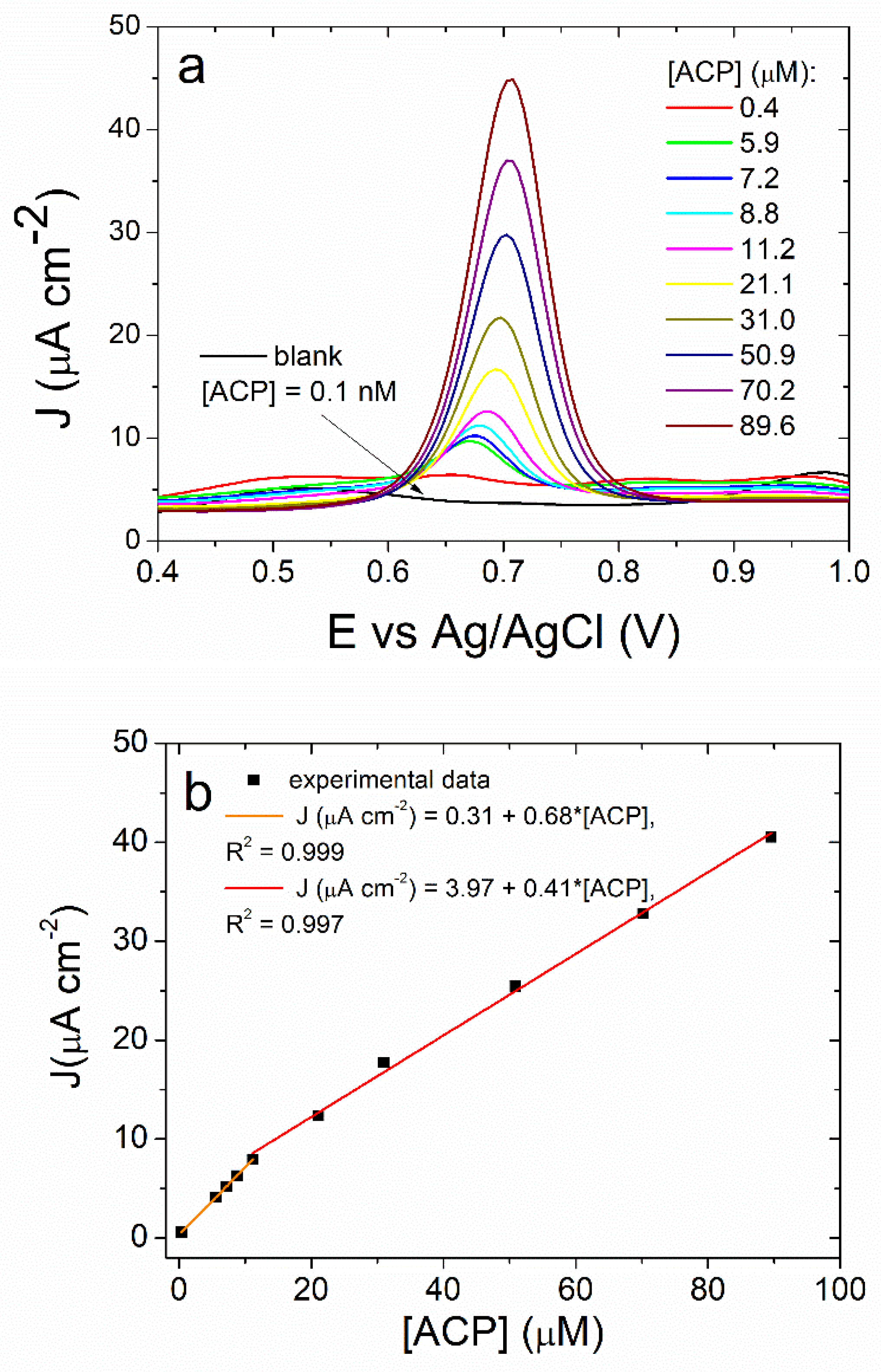
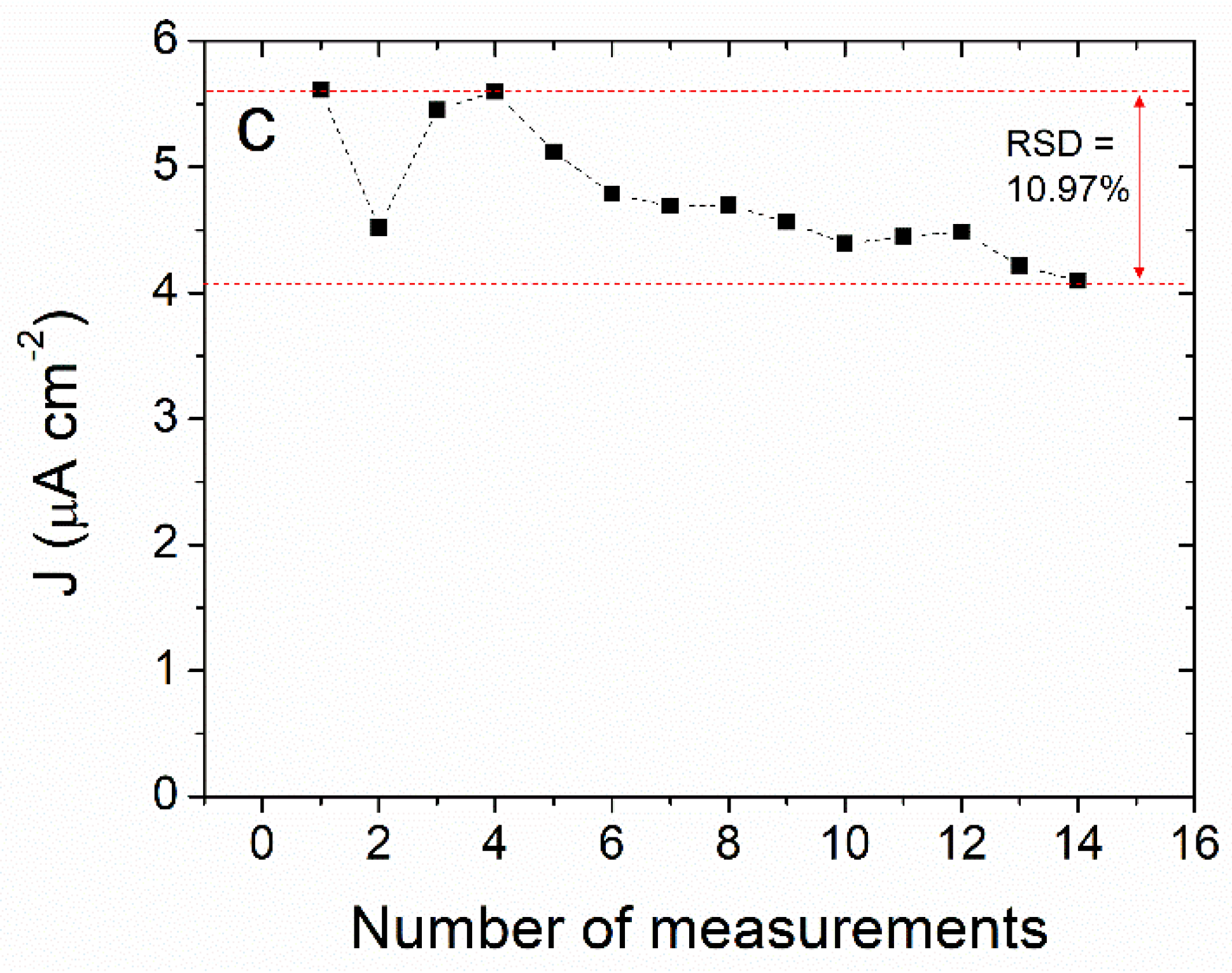
3.3. Differential Pulse Voltammetry Determination of ACP Using the ITO/(NiTsPc/CeO2)-10 Electrode

Figure 4 shows the voltammograms for different concentrations of ACP obtained by means of DPV. Optimization of DPV conditions were investigated and the results are reported in the Supplementary Material, Figure S4. The best operation conditions were as follows: sodium acetate buffer: 0.1 M, pH 3; scan rate: 10 mV s−1; pulse amplitude: 50 mV; pulse time: 25 ms; starting potential: −0.4 V; deposition and rest times: 120 s and 30 s; N2 purge: no; and stirring: no. As shown in Figure 4a,b, the ACP oxidation current scaled with its concentration in the range between 0.4 µM and 89.6 µM. There was a slight shift of the oxidation peak to higher potentials as the ACP concentration increased, which could be caused by an ohmic loss due to ACP adsorption onto the electrode as well as erosion of the nanofilm. Figure 4b shows that there were two linear regimes; the first one (in orange), which spanned from 0.4 µM to 11.2 µM and is fitted by: J = 0.31 + 0.68*[ACP], R2 = 0.999; the second one (in red) spanned from 11.2 µM to 89.6 µM and was fitted by J = 3.97 + 0.41*[ACP], R2 = 0.997. The limit of detection (LOD) was determined for the first regime using the following equation:
L O D = 3 × R S S N 2 b
where RSS is the residual sum of squares (4.62 × 10⁻⁴), N is the number of experimental points (=5), and b is the slope of the calibration curve (Figure 4b, in orange). The value found for the LOD was 54.7 nM, which is among the lowest found in the literature (please refer to Table 1). As shown in Figure 4c, the electrode’s response decreased by 10.97% after fourteen consecutive runs, which is below the limit established by the AOAC methods [17] to be considered as reproducible. The decrease was due to a gradual erosion of the (NiTsPc/CeO2) film after being submitted to successive operation cycles.
Figure S5 reports the results for the determination of ACP in pharmaceutical tablets, comparing UV-Vis spectroscopy and DPV (using the ITO/(NiTsPc/CeO2)-10). According to the data, the value found by UV-Vis spectroscopy was 745.56 ± 12.74 mg, whereas DPV gave a value of 744.03 ± 33.00 mg. The package label indicates 750 mg, thus showing that both methods are reliable. Moreover, the Student’s t-test indicated that both methods were statistically identical at a 95% confidence level. Figure S6 displays the DPV curves for ACP added in different concentrations to synthetic urine. The typical electrochemical behavior of ACP was observed in both ranges of ACP concentrations (1.0–2.8 µM and 50–130 µM), whereas the recoveries for 1 µM and 50 µM of added ACP were 99.3% and 105.6%, respectively. A similar performance was observed during determination of ACP in tap water. For ACP added at 1 µM, 5 µM, and 50 µM, the recoveries were, respectively, 99.3%, 99.8%, and 101.4%.
The influence of interfering species, such as other CECs was investigated. As shown in Figure S7 and Table S2, determination of ACP (10 µM) was not affected by the presence of six different CECs at the same concentration, namely amoxicillin, atenolol, caffeine, ibuprofen, diclofenac, and ethinyl estradiol.

4. Conclusions

Differential pulse voltammetry performed with indium-doped tin oxide (ITO) electrodes surface-modified with a nanofilm of nickel(II) tetrasulfonated phthalocyanine (NiTsPc) and cerium oxide nanoparticles (CeO2) proved to be an effective way of detecting acetaminophen, which is a contaminant of emerging concern. Proper adjustment of the ITO/NiTsPc/CeO2 electrode nanoarchitecture enabled the electronic communication between Ni(II) and Ce(III)/Ce(IV) and allowed detection of acetaminophen in different matrices including tap water and synthetic urine at a very low limit of detection. The electrode response was quite stable and seemed to be insensitive to the presence of at least six contaminants of emerging concern. In summary, the ITO/NiTsPc/CeO2 electrode shows a great potential for acetaminophen detection in aqueous samples.

Supplementary Materials

The following are available online at https://0-www-mdpi-com.brum.beds.ac.uk/article/10.3390/chemosensors11030154/s1, Figure S1: Structural features of CeO2 nanoparticles; Figure S2: EIS spectra of ferri/ferrocyanide and acetaminophen; Figure S3: CV of acetaminophen with different electrode nanoarchitectures; Figure S4: DPV experiments for optimization of the measurement conditions; Figure S5: Determination of acetaminophen in pharmaceutical tablet; Figure S6: Determination of acetaminophen in synthetic urine; Figure S7: Study of interfering species. Table S1: Fitting parameters for EIS spectra of acetaminophen; Table S2: Relative error of the electrochemical signal for acetaminophen in the presence of interfering species.

Author Contributions

Conceptualization, E.C.G., C.L.R. and L.G.P.; methodology, E.C.G. and C.L.R.; validation, E.C.G., C.L.R. and V.O.S.J.; investigation, E.C.G., C.L.R. and V.O.S.J.; formal analysis, E.C.G., C.L.R. and L.G.P.; writing—original draft preparation, E.C.G., C.L.R. and L.G.P.; writing—review and editing, E.C.G., C.L.R. and L.G.P.; supervision, L.G.P.; project administration, L.G.P. All authors have read and agreed to the published version of the manuscript.

Funding

This research was funded by Conselho Nacional de Desenvolvimento Científico e Tecnológico (CNPq), grant number 313223/2021-1; Coordenação de Aperfeiçoamento de Pessoal de Nível Superior (Capes), finance code 001; and Fundação de Apoio à Pesquisa do Distrito Federal (FAPDF), grant number 00193.00001824/2022-64.

Informed Consent Statement

Not applicable.

Data Availability Statement

Data are available from authors upon reasonable request.

Acknowledgments

The authors are thankful to the Brazilian funding agencies CNPq, CAPES, and FAPDF. The authors also thank the Laboratório Multiusuário de Microscopia de Alta Resolução (LabMic-UFG) for the TEM and SEM measurements and M.F.P Silva (University of Brasilia) for his valuable discussions.

Conflicts of Interest

The authors declare no conflict of interest.

References

  1. Warwick, C. Paracetamol and fever management. J. R. Soc. Promot. Health 2008, 128, 320–323. [Google Scholar] [CrossRef]
  2. Saragiotto, B.T.; Shaheed, C.A.; Maher, C.G. Paracetamol for pain in adults. BMJ 2019, 367, l6693. [Google Scholar] [CrossRef] [PubMed]
  3. Lee, W.J.; Goh, P.S.; Lau, W.J.; Ismail, A.F. Removal of pharmaceutical contaminants from aqueous medium: A state-of-the-art review based on paracetamol. Arab. J. Sci. Eng. 2020, 45, 7109–7135. [Google Scholar] [CrossRef]
  4. Sharma, R.K.; Raju, G.; Sarkar, P.; Singh, H.; Singla, E. Comparing the environmental impacts of paracetamol dosage forms using life cycle assessment. Environ. Dev. Sustain. 2022, 24, 12446–12466. [Google Scholar] [CrossRef]
  5. Agarwal, N. Paracetamol-A contaminant of high concern: Existence in environment and adverse effects. Pharmaceut. Drug Regul. Affair J. 2021, 4, 000128. [Google Scholar] [CrossRef]
  6. Benson, R.; Conerly, O.D.; Sander, W.; Batt, A.L.; Boone, J.S.; Furlon, E.T.; Glassmeyer, S.T.; Kolpin, D.W.; Mash, H.E.; Schenck, K.M.; et al. Human health screening and public health significance of contaminants of emerging concern detected in public water supplies. Sci. Total Environ. 2017, 579, 1643–1648. [Google Scholar] [CrossRef]
  7. Montaseri, H.; Forbes, P.B.C. Analytical techniques for the determination of acetaminophen: A review. Trends Analyt. Chem. 2018, 108, 122–134. [Google Scholar] [CrossRef]
  8. Sivaranjanee, R.; Kumar, P.S.; Saravanan, R.; Govarthanan, M. Electrochemical sensing system for the analysis of emerging contaminants in aquatic environment: A review. Chemosphere 2022, 294, 133779. [Google Scholar] [CrossRef]
  9. Nematollahi, D.; Shayani-Jam, H.; Alimoradi, M.; Niroomand, S. Electrochemical oxidation of acetaminophen in aqueous solutions: Kinetic evaluation of hydrolysis, hydroxylation and dimerization processes. Electrochim. Acta 2009, 54, 7407–7415. [Google Scholar] [CrossRef]
  10. Li, X.; Kang, J.; Ji, H.; Gong, P.; Li, N. Past, present and future of electroanalytical sensor for aspirin, ibuprofen and paracetamol detection. Curr. Pharm. Anal. 2022, 18, 24–33. [Google Scholar]
  11. Zhang, F.; Wang, P.; Koberstein, J.; Khalid, S.; Chan, S.W. Cerium oxidation state in ceria nanoparticles studied with X-ray photoelectron spectroscopy and absorption near edge spectroscopy. Surf. Sci. 2004, 563, 74–82. [Google Scholar] [CrossRef]
  12. Kusuma, K.B.; Manju, M.; Ravikumar, C.R.; Raghavendra, N.; Amulya, M.A.S.; Nagaswarupa, H.P.; Murthy, H.C.A.; Kumar, M.R.A.; Shekhar, T.R.S. Photocatalytic degradation of methylene blue and electrochemical sensing of paracetamol using cerium oxide nanoparticles synthesized via sonochemical route. Appl. Surf. Sci. Adv. 2022, 11, 100304. [Google Scholar] [CrossRef]
  13. Azeredo, N.F.B.; Gonçalves, J.M.; Lima, I.S.; Araki, K.; Wang, J.; Angnes, L. Screen-printed nickel-cerium hydroxide sensor for acetaminophen determination in body fluids. Chemeletrochem 2021, 8, 2505–2511. [Google Scholar] [CrossRef]
  14. Stanković, D.M.; Ognjanović, M.; Jović, M.; Cuplić, V.; Lesch, A.; Girault, H.H.; Jankulović, M.G.; Antić, B. Disposable biosensor based on amidase/CeO2/GNR modified inkjet-printed CNT electrodes-droplet based paracetamol detection in biological fluids for “point-of-care” applications. Electroanalysis 2019, 8, 1517–1525. [Google Scholar] [CrossRef]
  15. Ponnaiah, S.K.; Prakash, P.; Vellaichamy, B. A new analytical device incorporating a nitrogen doped lanthanum metal oxide with reduced graphene oxide sheets for paracetamol sensing. Ultrason. Sonochem. 2018, 44, 196–203. [Google Scholar] [CrossRef] [PubMed]
  16. Sivakumar, M.; Sakthivel, M.; Chen, S.-M. One pot synthesis of CeO2 nanoparticles on a carbon surface for the practical determination of paracetamol content in real samples. RSC Adv. 2016, 6, 104227–104234. [Google Scholar] [CrossRef]
  17. AOAC International. Official Methods of Analysis in Guidelines for Standard Method Performance Requirements (Appendix F); AOAC International: Rockville, MD, USA, 2016. [Google Scholar]
  18. Goes, E.J.A., Jr.; Roedera, J.S.; Oliveira, K.B.L.; Gois, L.C.; Ferreira, M.P.; Silva, J.G. UV spectrophotometry method validation for quantification of paracetamol in tablet formulations: A proposal of experimental activity for instrumental analysis. Orbital Electron. J. Chem. 2018, 10, 561–567. [Google Scholar]
  19. Ribeiro, C.D.; de Souza, J.R.; Pereira-da-Silva, M.A.; Paterno, L.G. Voltammetric detection of ethinylestradiol in water and synthetic urine samples using a Ni(II) phthalocyanine/iron oxide nanocomposite electrode. Electroanalysis 2020, 33, 609–617. [Google Scholar] [CrossRef]
  20. Babitha, K.K.; Sreedevi, A.; Priyanka, K.P.; Sabu, B.; Varghese, T. Structural Characterization and optical studies of CeO2 nanoparticles synthesized by chemical precipitation. Indian J. Pure Appl. Phys. 2015, 53, 596–603. [Google Scholar]
  21. Spanier, J.E.; Robinson, R.D.; Zhang, F.; Chan, S.-W.; Herman, I.P. Size-dependent properties of CeO2 nanoparticles as studied by Raman scattering. Phys. Rev. B 2001, 64, 245407. [Google Scholar] [CrossRef] [Green Version]
  22. Snow, A.W. Phtalocyanine aggregation. In The Porphyrin Handbook; Elsevier: New York, NY, USA, 2003; Volume 17, pp. 129–176. ISBN 9780123932273. [Google Scholar]
  23. Schlenoff, J.B.; Ly, H.; Li, M. Charge and mass balance in polyelectrolyte multilayers. J. Am. Chem. Soc. 1998, 120, 7626–7634. [Google Scholar] [CrossRef]
  24. Ribeiro, C.D.; de Souza, J.R.; Pereira-da-Silva, M.A.; Santos, V.O.; Paterno, L.G. Electrocatalytic oxidation of ethinyl estradiol by an iron oxide nanoparticle/nickel phthalocyanine supramolecular electrode. J. Phys. Chem. C 2020, 124, 19057–19069. [Google Scholar] [CrossRef]
  25. Silva, J.C.O.; Sousa, M.H.; Tourinho, F.A.; Rubim, J.C. Raman spectroscopic investigation of maghemite ferrofluids modified by the adsorption of zinc tetrasulfonated phthalocyanine. Langmuir 2002, 18, 5511–5515. [Google Scholar] [CrossRef]
  26. Alencar, W.S.; Crespilho, F.N.; Santos, M.R.M.C.; Zucolotto, V.; Oliveira, O.N.; Silva, W.C. Influence of film architecture on the charge-transfer reactions of metallophthalocyanine layer-by-layer films. J. Phys. Chem. C 2007, 111, 12817–12821. [Google Scholar] [CrossRef]
  27. Mphuthi, N.G.; Adekunle, A.S.; Fayemi, O.E.; Olasunkanmi, L.O.; Ebenso, E.E. Phthalocyanine doped metal oxide nanoparticles on multiwalled carbon nanotubes platform for the detection of dopamine. Sci. Rep. 2017, 7, 43181. [Google Scholar] [CrossRef] [Green Version]
  28. Coelho, M.K.L.; da Silva, D.N.; Pereira, A.C. Development of electrochemical sensor based on carbonaceal and metal phthalocyanines materials for determination of ethinyl estradiol. Chemosensors 2019, 7, 32. [Google Scholar] [CrossRef] [Green Version]
  29. Zagal, J.H.; Griveau, S.; Silva, J.F.; Nyokong, T.; Bedioui, F. Metallophthalocyanine-based molecular materials as catalysts for electrochemical reactions. Coord. Chem. Rev. 2010, 254, 2755–2791. [Google Scholar] [CrossRef]
  30. Cheng, Y.; Veder, J.P.; Thomsen, L.; Zhao, S.; Saunders, M.; Demichelis, R.; Liu, C.; De Marco, R.; Jiang, S.P. Electrochemically substituted metal phthalocyanines, e-MPc (M = Co, Ni), as highly active and selective catalysts for CO2 reduction. J. Mater. Chem. A 2018, 6, 1370–1375. [Google Scholar] [CrossRef]
  31. Thill, A.S.; Figueiredo, W.T.; Lobato, F.O.; Vaz, M.O.; Fernandes, W.P.; Carvalho, V.E.; Soares, E.A.; Poletto, F.; Teixeira, S.R.; Bernardi, F. New horizons in photocatalysis: The importance of mesopores for cerium oxide. J. Mater. Chem. A 2020, 8, 24752–24762. [Google Scholar] [CrossRef]
  32. Tinh, V.D.C.; Thuc, V.D.; Kim, D. Chemically sustainable fuel cells via layer-by-layer fabrication of sulfonated poly(arylene ether sulfone) membranes containing cerium oxide nanoparticles. J. Membr. Sci. 2021, 634, 119430. [Google Scholar] [CrossRef]
  33. Azizi, S.; Asadpour-Zeynali, K. Electrochemical synthesis of tungstate bimetallic nanoparticles with application in electrocatalytic determination of paracetamol. ChemistrySelect 2022, 7, e202104548. [Google Scholar]
Scheme 1. Illustration for the layer-by-layer deposition of the (NiTsPc/CeO2) nanofilm showing the molecular structure of NiTsPc and crystal structure of CeO2 and a digital photo of the ITO/(NiTsPc/CeO2)-10 electrode.
Chemosensors 11 00154 sch001
Figure 1. UV-Vis absorption spectra of (a) NiTsPc solution and CeO2 suspension, and (b) nanofilm deposited onto quartz substrate with different numbers of (NiTsPc/CeO2) bilayers, where the inset shows the dependence of the nanofilm’s absorbance on the number of bilayers at 291 nm (r2 = 0.98), 620 nm (r2 = 0.99), and 665 (r2 = 0.99). (c) Raman spectra of plain NiTsPc and (NiTsPc/CeO2)-10 nanofilms, (d) EDS spectra and (e) SEM micrograph of the (NiTsPc/CeO2)-10 nanofilm deposited onto ITO substrate. Scale bar in (d) is 100 nm.
Chemosensors 11 00154 g001
Figure 2. (a) Cyclic voltammograms registered in plain electrolyte (0.1 M sodium acetate, pH 3) and in ACP solution (20 µM) using bare ITO and ITO/(NiTsPc/CeO2)-10. Scan rate: 25 mV s−1. (b) Dependence of ACP oxidation current density on the number of (NiTsPc/CeO2) bilayers.
Chemosensors 11 00154 g002
Figure 3. (a) Cyclic voltammograms of ACP (20 µM) in sodium acetate buffer (0.1 M, pH 3) registered with the ITO/(NiTsPc/CeO2)-10 electrode at different scan rates (50–175 mV s−1). (b) Dependence of the oxidation current density (Jpa) on the scan rate, (c) Tafel plot of the ACP oxidation peak at 50 mV s−1, and (d) dependence of the peak potential (Epa) on ln v.
Chemosensors 11 00154 g003
Figure 4. (a) DPV curves registered with the ITO/(NiTsPc/CeO2)-10 electrode for different concentrations of ACP (0.4 µM to 89.6 µM). (b) Variation of the oxidation current with the ACP concentration. (c) Variation of the oxidation current with the number of consecutive DPV runs for a fixed ACP concentration (10 µM). DPV conditions: scan rate, 10 mV s−1; pulse amplitude, 50 mV; pulse time: 25 ms; electrolyte: sodium acetate buffer, 0.1 M and pH 3.
Chemosensors 11 00154 g004aChemosensors 11 00154 g004b
Table 1. Configuration and performance of different electroanalytical methods for determination of acetaminophen.
ElectrodeMethodLinear RangeLOD (nM)Ref
CPE/CeO2CV1–5 mM1 × 106[12]
SPE/α-Ni0.9Ce0.1(OH)2CV100–1000 mM1700[13]
CNT/amidase/CeO2/GrSWV1–100 μM180[14]
GCE/N-CeO2/rGODPV0.05–0.600 μM9.8[15]
GCE/CeO2-CDPV1–1219 µM70[16]
GCE/CoNiWO4-NSDPV10–1000 µM1451[33]
ITO/(NiTsPc/CeO2)DPV0.4–11.2 µM54.7This work
CPE: carbon paste electrode, SPE: screen-printed electrode, CNT: carbon nanotubes, Gr: graphene, rGO: reduced graphene oxide, ITO: indium-doped tin oxide.
Disclaimer/Publisher’s Note: The statements, opinions and data contained in all publications are solely those of the individual author(s) and contributor(s) and not of MDPI and/or the editor(s). MDPI and/or the editor(s) disclaim responsibility for any injury to people or property resulting from any ideas, methods, instructions or products referred to in the content.

