Article

Experimental Study on the Separation Performance of an Intermittent Discharge Concentrated Hydrocyclone

College of Mechanical & Electronic Engineering, Shandong University of Science and Technology, Qingdao 266590, China
*
Author to whom correspondence should be addressed.
Submission received: 1 February 2023 / Revised: 20 February 2023 / Accepted: 24 February 2023 / Published: 25 February 2023
(This article belongs to the Special Issue Research on Separation Performance of Separator)

Abstract

:
In the pretreatment for the solid–liquid separation of sewage, the traditional hydrocyclone cannot reasonably achieve a high underflow concentration and high separation efficiency at the same time. An intermittent discharge concentrated hydrocyclone was proposed in this paper to solve this problem. In order to determine the specific separation performance of the intermittent discharge concentrated hydrocyclone, this paper studied the influence of the structure parameters and process parameters on its separation performance through experimental testing. The results indicate that increasing the overflow backpressure improves the separation efficiency but reduces the underflow concentration; that increasing the diameter of the overflow pipe and reducing the diameter of the underflow orifice improve the underflow concentration but reduce the separation efficiency; and that a proper increase in the inlet pressure simultaneously increases the separation efficiency and underflow concentration. The parameter combinations of the hydrocyclone were separately optimized for the underflow concentration and total separation efficiency.

Graphical Abstract

1. Introduction

A hydrocyclone can generate a centrifugal force field to separate materials with different densities or different grain sizes. It has been widely applied in many fields (such as for concentration, classification, and clarification) due to its simple structure, high separation efficiency, convenient operation, and small size [1,2,3]. In sewage treatment, the solids in sewage usually have varied particle sizes and small specific gravity, which makes separation from the liquid fraction difficult [4,5,6]. Flocculation settling results in a high cost due to chemical consumption [7,8,9], while membrane filtration can easily cause blockage, which reduces the membrane flux and limits the processing capacity of the membrane filtration process [10,11,12]. Therefore, in order to ensure the stable operation of the subsequent equipment, the hydrocyclone is often used in the first process to remove most of the solid particles from the sewage [13,14,15]. In order to remove the solid particles from the sewage to the maximum extent and recover the liquid phase, the hydrocyclone must have a higher separation efficiency to achieve a high solid removal efficiency and a higher underflow concentration to ensure a high recovery rate of the liquid phase [16,17]. Restricted by the separation principle, the traditional cylindrical-conical hydrocyclone cannot reasonably achieve a high separation efficiency and high underflow concentration at the same time [18,19,20]. Reducing the diameter of the underflow orifice is the most common method to improve the underflow concentration, but this method leads to a lower separation efficiency and muddy overflow [21,22]. Although increasing the diameter of the underflow orifice can improve the separation efficiency, the underflow rate is increased, the underflow concentration is decreased, and the flow rate of the liquid phase recovered by the overflow is decreased [23,24]. Therefore, simultaneously improving the underflow concentration and total separation efficiency has become a popular topic and difficult challenge in water treatment and hydrocyclone research.
In order to improve the separation efficiency of the hydrocyclone, many scholars have studied the hydrocyclone from the perspectives of structural innovation and parameter optimization [25,26,27,28,29]. Vieira et al. [30] replaced the traditional conical section with a conical filtering wall. When the pulp rotates downward along the conical filtering wall, part of the liquid can penetrate the filtering wall for separate recovery. The pulp with increased concentration continues to rotate downward and enter the underflow. Finally, it can be separated to obtain three products (i.e., the overflow, underflow, and filtrate). Ghodrat et al. [31] studied convex- and concave-curved conical hydrocyclones with different curvatures and their results revealed that the concave-curved cone could help improve the separation efficiency and reduce the particle content in the overflow. Yang et al. [32] proposed a double-cone hydrocyclone to replace the traditional single-cone hydrocyclone and found that cone combinations could improve the separation efficiency and separation accuracy of the hydrocyclone. Yang et al. [33] conducted an optimization study on the size of the hydrocyclone inlet and their results indicated that increasing the size of the feed inlet could improve the stability of the internal flow field of the hydrocyclone and increase the particle separation efficiency. According to the study conducted by Zhou et al. [34], although increasing the height of the cylinder section could improve the total separation efficiency, the underflow flow rate also increases. Bicalho et al. [35] found that increasing the feed flow within a certain range could increase the intensity of the centrifugal force field in the hydrocyclone and improve the total separation efficiency. Nevertheless, an excessively large flow rate reduced the particles’ effective retention time and lowered the total separation efficiency. Liu et al. [36] controlled the separation performance of the hydrocyclone by setting a backpressure at the outlet of the overflow pipe and found that an appropriate increase in the overflow backpressure could improve the total separation efficiency and greatly increase the recovery rate of fine particles. On the basis of these studies, this paper proposed an intermittent discharge concentrated hydrocyclone that could improve the total separation efficiency by setting a backpressure at the overflow outlet and raise the underflow concentration by providing an intermittent discharge concentrated hopper at the underflow orifice.
Although numerical simulation has been widely applied in research on the separation performance of hydrocyclones, the experimental method is still more reliable for the study of a high concentration flow field. Therefore, in order to accurately determine the separation performance of the intermittent discharge concentrated hydrocyclone, this paper studied the influence of the structure parameters and process parameters on its separation performance through traditional experimental testing and optimizing the related parameters.

2. Materials and Methods

2.1. Apparatus

During the process of separation, the traditional cylindrical-conical hydrocyclone cannot simultaneously achieve a high underflow concentration and high total separation efficiency. This paper optimized and improved the underflow concentration and total separation efficiency of the hydrocyclone. First, in order to solve the problem of a low separation efficiency of the common hydrocyclone, a backpressure valve was connected to the overflow pipe of the hydrocyclone to regulate the backpressure at the overflow outlet. Increasing the backpressure at the overflow outlet could improve the upward resistance of the liquid and reduce the possibility of particles entering the overflow. At the same time, a valve connected to the overflow pipe could reduce the amount of air flowing back into the hydrocyclone through the overflow pipe and the influence of the air column on the separation performance of the hydrocyclone. Second, to improve the underflow concentration, an intermittent discharge concentrated hopper was provided at the underflow orifice of the hydrocyclone, as shown in Figure 1. After the material entered the concentrated hopper through the underflow orifice, particles deposited longer in the hopper due to the increased separation space and declined slurry velocity. In the meantime, the fluid flowed slowly in the concentrated hopper, the flow field became more stable, and the particles naturally descended and accumulated at the bottom. On the other hand, particles constantly entered the concentrated hopper from the hydrocyclone, resulting in a smaller content of the water phase and a larger concentration of particles in the hopper. The valve was opened when the concentration of the material reached a certain value at the bottom of the concentrated hopper so that the material was discharged from the outlet.
For the convenience of replacing the underflow orifice, a tray was installed at the junction. The inverted conical shape of the concentrated hopper with a taper angle of 60° could reduce the outflow velocity of the material and improve its concentration performance as much as possible. To fill the concentrated hopper with the material, the volume capacity of the concentrated hopper was designed according to the underflow rate (i.e., a diameter of 200 mm and an overall height of 320 mm). At the outlet of the concentrated hopper, a pneumatic ball valve was installed through a threaded connection. With the help of a timer relay, the valve could be intermittently closed to increase the concentration time of the material in the concentrated hopper. The specific structure parameters of the hydrocyclone are shown in Table 1.
This test employed a closed-circuit circulating system to ensure the stable operation of the hydrocyclone. The test system was mainly composed of the hydrocyclone, a pneumatic valve, a backpressure valve, a slurry pump, a pressure gauge, and a stirring device, as shown in Figure 2. During the test process, water and quartz sand were mixed to the required concentration in proportion in the stirring tank and stirred with the stirring device. Then, the slurry pump supplied the material to the hydrocyclone for concentration and separation. The overflow and underflow returned to the stirring tank to form a closed loop. After the system became stable, it was sampled several times to reduce the test error and improve the accuracy of the test data. During the test, the thickening of materials was strengthened by adding a pneumatic valve to the thickening hopper outlet and using a time relay to control the valve to open and close intermittently. In order to investigate the changes of the underflow and overflow concentration during the whole concentration process, the time relay was activated after the system was stabilized, and different concentration times were set and discharged to take samples. Each concentration time was incremented by 20 s for the intermittent discharge test.

2.2. Materials

The material used in this test was quartz powder with a purity of 98% and a particle density of 2650 kg/m3. The distribution of the particle size is shown in Figure 3. The data indicate that 25.73% of the particles had a diameter less than 15 μm, 66.43% had a diameter less than 45 μm, and 15.75% had a diameter larger than 70 μm.

2.3. Experimental Design

A reasonable test arrangement can help us systematically explore the concentration performance of the hydrocyclone and the influence of various variables on the performance of the hydrocyclone in a short period of time. The specific arrangement was as follows: (1) the method of controlling variables was used to determine a feed pressure of 0.12 MPa, overflow pipe diameter of 36 mm, underflow orifice diameter of 18 mm and overflow backpressure of 17 kPa as the basic parameters to carry out the single-factor test to explore how the concentration performance of the hydrocyclone changes under different parameter settings, and (2) an orthogonal test with the underflow concentration and total separation efficiency as the evaluation indicators was conducted to obtain the best parameter combinations. Then, an orthogonal test analysis table was established according to the test results, and K i j denotes the sum of the results of the j-th level test for the i-th factor, and k denotes the average test result for the i-th factor. The optimal combination of parameters can be determined based on the magnitude of the k combined with the evaluation index. The R value is expressed as the difference between the maximum value and the minimum value of the i-th factor test result, which characterizes the magnitude of the influence of each factor on the performance evaluation index. The larger the R value, the more the performance index is influenced by the factor to determine the primary and secondary relationship between the magnitude of the influence of each factor on the separation performance. The test parameters are shown in Table 2.

2.4. Performance Index

The total separation efficiency is defined as the mass flow rate reporting to the underflow divided by feed mass flowrate. This mass flow rate of the solid phase includes the mass flow rate of all solid particles of different particle sizes, which is used to characterize the total recovery rate of the solid phase particles from the underflow. The calculation formula is shown in Equation (1).
E = M u M i × 100 %
where M i , M u are the solid-phase mass flow rate of the feed and underflow.
The comprehensive classification efficiency can reflect the separation effect of a specific particle level. For the concentration of hydrocyclone, the comprehensive classification efficiency can be calculated using Equation (2).
G = ( α γ ) ( β α ) α ( β γ ) ( 100 α ) × 10000 %
where α is the content of a particular particle size in the feed; β is the content of a particular particle size in the overflow; γ is the content of a particular particle size in the underflow.
The concentration ratio represents the increase in the underflow concentration compared to the feed concentration and is used to measure the concentration effect of the hydrocyclone, which can be calculated by Equation (3).
T = C u C i
where C i , C u are the concentration of the feed and underflow.

3. Results and Discussion

The product concentration, total separation efficiency, concentration ratio, and comprehensive classification efficiency were considered as the performance indicators to explore how the concentration performance of the hydrocyclone changed under different structure parameters and operating parameters. During the test process, to deeply explore how the underflow concentration changed with the concentration time under different test variables, samples were taken at the concentration time points of 80 s, 100 s, 120 s, 140 s, and 160 s and at the discharge time point of 3 s to obtain the underflow concentrations. The products at 120 s were selected to compare the performance indicators under different variables.

3.1. Effect of Overflow Backpressure on the Concentration Performance

Backpressure can increase the resistance for the fluid to enter the overflow pipe to some degree, causing particles to stay longer for full separation. Table 3 shows the change in the underflow concentration under different overflow backpressures.
The underflow concentration decreased from 54.17% to 47.37% at 120 s because after the overflow backpressure increased, the fluid discharge through the overflow pipe was difficult, and more water entered the concentrated hopper, which lowered the concentration in the concentrated hopper and thus reduced the underflow concentration after the concentrating process. Analysis of Figure 4, which shows the effect of changes in the overflow backpressure on the separation performance of the intermittent discharge concentrated hydrocyclone, revealed that increasing the overflow backpressure could reduce the proportion of the solid phase in the overflow and decrease the overflow concentration from 2.23% to 1.86%. With the increase in the overflow backpressure, the concentration ratio decreased from 13.54 to 11.84. This finding indicates that an excessively high overflow backpressure reduces the concentration efficiency of the hydrocyclone, which makes it difficult to obtain a high-concentration underflow product. The total separation efficiency was positively correlated with the backpressure. The overflow backpressure increased from 11 kPa to 23 kPa. The total separation efficiency increased by 9.53%, and the split ratio also increased from 0.021 to 0.055, because the greater the overflow backpressure, the smaller the overflow rate and the more easily particles enter the underflow instead of the overflow. As a result, both the total separation efficiency and split ratio increase.
Table 4 shows how the content of −45 μm particles in the product at each outlet changed with the overflow backpressure. The table indicates that with the increase in the overflow backpressure, the content of −45 μm particles in the overflow increased from 86.32% to 90.47%, indicating that the particle size in the overflow gradually decreased. The content of −45 μm particles in the underflow increased from 34.32% to 45.35%, and the total efficiency decreased from 55.27% to 50.36%. After the overflow backpressure increased, the upward resistance of the fluid rose and the axial velocity at the axis of the hydrocyclone decreased so that the fine particles had difficulty in entering the overflow pipe. On the other hand, increasing the overflow backpressure forced part of the fluid to enter the concentrated hopper through the underflow orifice. In turn, the muddy overflow was reduced to a certain extent, but the entrainment of fine particles by the underflow was enhanced, resulting in an increase in the content of −45 μm particles in the underflow. The table revealed that the contents of particles in the overflow and underflow at an overflow backpressure of 11 kPa showed little difference from those at an overflow backpressure of 14 kPa. Therefore, the overflow backpressure at this moment did not have a large impact on the trajectories of the fine particles.

3.2. Effect of Overflow Pipe Diameter on the Concentration Performance

As the main channel for the formation of the air column in the hydrocyclone, the overflow pipe had a large influence on the concentration and separation performance of the hydrocyclone. Figure 5 shows how the underflow concentration changed under different overflow pipe diameters. Upon the analysis of the data in Table 5, changes in the overflow pipe diameter had a great influence on the underflow concentration. With the increase in the overflow pipe diameter, the underflow concentration increased from 41.35% to 56.97% at 120 s, because when the overflow pipe diameter increased, the overflow rate increased, and the amount of water entering the underflow decreased. As a result, the underflow concentration became larger. Moreover, when the overflow pipe diameter reached 44 mm, changes in the underflow concentration were no longer obvious after 100 s, which indicates that a large overflow pipe diameter can help reduce the concentration time.
Figure 5 shows the impact of the overflow pipe diameter on the separation performance of the hydrocyclone. The figure indicates that with the increase in the overflow pipe diameter, the particles could more easily enter the overflow, and the proportion of the solid phase in the overflow increased, with the concentration increasing from 1.73% to 2.31% and the concentration ratio increasing from 10.58 to 14.24. Furthermore, the changes in the overflow pipe diameter had a great influence on the total separation efficiency. With the increase in the overflow pipe diameter, the total separation efficiency continuously decreased from 59.16% to 44.03%. When the overflow pipe diameter increased from 32 mm to 36 mm, the total separation efficiency sharply decreased, indicating that a large number of solid particles were discharged from the overflow at this moment. The split ratio decreased from 0.073 to 0.018, showing a large gradient because generally, the overflow pipe is the main pressure outlet of the hydrocyclone. When its diameter increases, the overflow rate changes considerably, which changes the underflow rate.
Table 6 indicates how the content of −45 μm particles in each product changed under different overflow pipe diameters. The content of −45 μm particles in the overflow was greatly affected by the changes in the overflow pipe diameter. With the increase in the diameter, the content of −45 μm particles in the overflow decreased from 91.61% to 85.87% (i.e., the particle size became larger). As the diameter increased, the overflow pipe had a greater ability to draw particles, so the overflow flow rate also increased accordingly. Some particles may even be directly carried by the fluid into the overflow pipe without separation. On the other hand, when the effect of the inner vortex flow was enhanced, particles could more easily leave the outer vortex flow and enter the inner vortex flow, which led to an increase in the particle content in the overflow and a decrease in the particle content in the underflow. As a result, the content of −45 μm particles declined from 49.64% to 31.34%, and the total efficiency increased from 45.17% to 56.10%.

3.3. Effect of Underflow Orifice Diameter on the Concentration Performance

The underflow orifice is an important outlet of the hydrocyclone. It determines the number of particles entering the concentrated hopper from the hydrocyclone. It is also an important structure parameter that affects the concentration performance of the hydrocyclone. Table 7 shows the underflow concentration under different underflow orifice diameters. With the increase in diameter, the underflow concentration decreased from 57.33% to 47.21% at 120 s. At the same time, the change in the underflow concentration when the diameter of the underflow orifice was 24 mm showed that the intermittent discharge method makes it possible to have a high underflow concentration when a large underflow orifice diameter is used. The table also indicates that when the underflow orifice diameter is 12 mm, the underflow concentration began to show little change after 80 s. Therefore, a small underflow orifice can help improve the initial concentration of the material in the concentrated hopper and reduce the time of concentration.
As shown in Figure 6, in the process of increasing the underflow orifice diameter from 12 mm to 24 mm, the overflow concentration decreased slightly, from 2.21% to 1.97%, and the concentration ratio decreased from 14.33 to 11.80. Additionally, with the increase in the underflow orifice diameter, the total separation efficiency and split ratio gradually increased from 46.61% to 52.95% and from 0.017 to 0.045, respectively. This increase occurred because as the underflow orifice diameter increased, the subsequent features of the particles near the underflow orifice were improved, and the particles therefore could more easily enter the concentrated hopper with the fluid. As a result, the total separation efficiency and underflow rate increased, and the split ratio increased accordingly. However, when the underflow rate increased, the amount of water entering the underflow also increased, which is not helpful for improving the underflow concentration.
Table 8 indicates changes in the content of −45 μm particles and the comprehensive classification efficiency of the product at each outlet under different underflow orifice diameters. According to the data in the table, when the underflow orifice diameter increased from 12 mm to 24 mm, the content of −45 μm particles in the underflow increased from 24.04% to 42.67%, and that in the overflow increased from 86.55% to 88.11%. This finding indicates that the particles in the overflow became fine. As the underflow orifice diameter increased, the downward resistance of the fluid decreased. In this case, the fine particles in the inner vortex flow could easily enter the underflow and flow to the concentrated hopper through the underflow orifice, leading to an increase in the content of fine particles in the underflow product. Calculations revealed that with the increase in the underflow orifice diameter, the comprehensive classification efficiency decreased from 61.18% to 50.83%.

3.4. Effect of Feed Pressure on the Concentration Performance

The feed pressure should be determined according to the material properties and requirements for the treatment capacity. An appropriate feed pressure can improve the separation size and underflow concentration of the hydrocyclone. In the experiment, the feed pressure of the hydrocyclone could be regulated through the inlet flow, which was controlled by changing the frequency of the slurry pump motor. The underflow concentrations under different pressures are shown in Table 9. The table indicates that as the pressure increased from 0.08 MPa to 0.16 Mpa, the concentration increased from 46.06% to 54.53% at 120 s. At the same time, when the pressure was between 0.14 Mpa and 0.16 Mpa, the underflow concentration changed little after 100 s. This finding indicates that the concentration time can be reduced by appropriately increasing the feed pressure.
According to Figure 7, as the feed pressure increased, the overflow concentration decreased from 2.21% to 1.93%, and the concentration ratio rose from 11.50 to 13.88, because the increase in feed pressure improved the concentration of the material itself to form a high-concentration layer at the bottom of the concentrated hopper. Hence, the concentration ratio increased. With the increase in feed pressure, the total separation efficiency increased from 46.75% to 53.61%. When the feed pressure increased, the tangential velocity of the fluid was improved, and the centrifugal force field was enhanced, which caused some fine particles to overcome the centripetal force and move toward the wall surface to enter the outer vortex flow and finally enter the concentrated hopper through the underflow orifice. Then, the total separation efficiency increased. It is inevitable that increasing the feed pressure improves the treatment capacity of the hydrocyclone. Since most of the fluid flows out from the overflow pipe, the overflow rate increases more than the underflow rate, causing the split ratio to decrease.
Table 10 shows the changes in the content of −45 μm particles and the comprehensive classification efficiency of each product under different feed pressures. According to the data in the table, when the pressure increased from 0.08 MPa to 0.16 MPa, the particle content in the overflow changed little, the content of −45 μm particles in the underflow increased from 35.88% to 40.27%, and the comprehensive classification efficiency decreased slightly from 54.83% to 52.55%. Therefore, with the increase in feed pressure, the tangential velocity increased, the ability of the outer vortex flow to capture fine particles improved, the content of fine particles in the underflow increased, and the separation size was reduced.

3.5. Parameter Optimization Test

According to the single-factor test results, the influence of different variables on the concentration performance of the hydrocyclone will vary. A comprehensive test requires an enormous amount of work. An orthogonal test features a fast speed, high accuracy, and small amount of workload. Accurate and reliable optimal parameter combinations can be identified by designing an orthogonal table and arranging a multifactor orthogonal test. A four-factor and three-level orthogonal test was arranged in this paper (feed pressure: 0.10 MPa, 0.12 MPa, and 0.14 MPa; underflow orifice diameter: 15 mm, 18 mm, and 21 mm; overflow backpressure: 14 kPa, 17 kPa, and 20 kPa; and overflow pipe diameter: 32 mm, 36 mm, and 40 mm). For the arrangement of the orthogonal test, see Table 11.

3.5.1. Optimization of the Underflow Concentration

Table 12 shows the analysis results of the orthogonal test data with the underflow concentration as the response. According to the range values in the table, the underflow concentration was affected by factors in the following order: overflow backpressure > underflow orifice diameter > overflow pipe diameter > feed pressure. The overflow backpressure had the greatest influence on the underflow concentration, with the R value reaching 4.35, because the overflow backpressure determines the resistance of the fluid entering the overflow pipe. When the overflow backpressure decreased, less water phase entered the concentrated hopper through the underflow orifice, which led to an increase in the underflow concentration. The second most influential factor was the underflow orifice diameter, with an R value of 2.81. When the underflow orifice diameter changed, the trajectories of particles in both the inner and outer vortex flows changed, which determines the number of particles that enter the concentrated hopper and thus affects the underflow concentration. Changes in the overflow pipe diameter had a large influence on the split ratio, causing the underflow concentration to change. The feed pressure showed the lowest impact on the underflow concentration. When it increased, the treatment capacity of the hydrocyclone increased, as did the flow at each outlet, which finally affected the material ratio in the overflow and underflow. According to the optimal values, when the underflow concentration is regarded as an evaluation indicator, the optimal parameter combination is as follows: feed pressure of 0.12 MPa, underflow orifice diameter of 15 mm, overflow backpressure of 14 kPa, and overflow pipe diameter of 40 mm.

3.5.2. Optimization of the Total Separation Efficiency

Table 13 shows the analytical results of the orthogonal test data with the total separation efficiency as the response. From the range value R, factors that affected the total separation efficiency of the hydrocyclone were obtained in the following order: underflow orifice diameter > overflow backpressure > overflow pipe diameter > feed pressure. When a concentrated hopper with a large diameter was used, the discharge flow of the material mainly depended on the underflow orifice diameter. When the underflow orifice diameter increased, the flow rate at the underflow orifice increased, and the number of concentrated particles entering the concentrated hopper through the underflow orifice increased, which finally resulted in a higher total separation efficiency. The second most influential factor that affected the total separation efficiency was the overflow backpressure. A large overflow backpressure could reduce the number of particles that enter the overflow to some degree and force them to be discharged from the underflow, thus increasing the proportion of solid particles in the underflow. An overflow pipe with a smaller diameter led to a smaller overflow rate so that more fluid entered the concentrated hopper through the underflow orifice to improve the total separation efficiency. The feed pressure had the lowest impact on the total separation efficiency. The larger the feed pressure, the stronger the centrifugal force field in the hydrocyclone, which is beneficial for the centrifugal separation of particles by reducing the number of fine particles entering the inner vortex flow and increasing the solid content in the underflow. For actual production that focused on improving the total separation efficiency, the optimal parameter combination was as follows: feed pressure of 0.14 MPa, underflow orifice diameter of 21 mm, overflow backpressure of 20 kPa, and overflow pipe diameter of 32 mm.

4. Conclusions

This paper studied the influence of the structure parameters and process parameters on the separation performance of an intermittent discharge concentrated hydrocyclone through experimental testing. The conclusions are as follows:
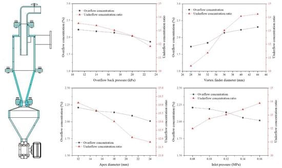
  • When the overflow backpressure increased, both the overflow concentration and underflow concentration decreased, both the total separation efficiency and split ratio increased, and the content of the −45 μm particles in the underflow significantly increased.
  • When the overflow pipe diameter increased from 28 mm to 44 mm, the underflow concentration and overflow concentration increased to varying degrees. The split ratio decreased significantly, the particle size in the underflow became larger, and the total separation efficiency decreased.
  • A small underflow orifice diameter could improve the underflow concentration and reduce the time of concentration. Increasing the feed pressure could improve both the concentration ratio and total separation efficiency.
  • The underflow concentration was influenced by various factors in the following order: overflow backpressure > underflow orifice diameter > overflow pipe diameter > feed pressure.
  • The total separation efficiency was influenced by various factors in the following order: underflow orifice diameter > overflow backpressure > overflow pipe diameter > feed pressure.

Author Contributions

P.L.: Conceptualization, writing—original draft preparation; H.W.: Methodology, software, formal analysis, writing—original draft preparation; L.J.: Conceptualization, funding acquisition, investigation, writing—review and editing; Y.Z. (Yuekan Zhang): Software, data curation; X.L.: Validation, data curation; Y.Z. (Yulong Zhang): Validation, data curation; Z.L.: Validation, data curation. All authors have read and agreed to the published version of the manuscript.

Funding

This work was supported by the National Natural Science Foundation of China (22108159) and the Natural Science Foundation of Shandong Province, China (ZR2021QB068, ZR2020ME105).

Data Availability Statement

Not applicable.

Conflicts of Interest

The authors declare no conflict of interest.

References

  1. Li, J.-P.; Zhao, W.; Li, S.-H.; Yang, X.-J.; Lyu, S.-G.; Liu, Y.-D.; Wang, H.-L. A novel hydrocyclone for use in underground DNAPL phase separation. Sci. Total Environ. 2022, 842, 156866. [Google Scholar] [CrossRef] [PubMed]
  2. Kuang, S.; Chu, K.; Yu, A.; Vince, A. Numerical study of liquid–gas–solid flow in classifying hydrocyclones: Effect of feed solids concentration. Miner. Eng. 2012, 31, 17–31. [Google Scholar] [CrossRef]
  3. Jiang, L.; Liu, P.; Zhang, Y.; Yang, X.; Wang, H.; Gui, X. Design boundary layer structure for improving the particle separation performance of a hydrocyclone. Powder Technol. 2019, 350, 1–14. [Google Scholar] [CrossRef]
  4. Mansour-Geoffrion, M.; Dold, P.L.; Lamarre, D.; Gadbois, A.; Déléris, S.; Comeau, Y. Characterizing hydrocyclone performance for grit removal from wastewater treatment activated sludge plants. Miner. Eng. 2010, 23, 359–364. [Google Scholar] [CrossRef]
  5. Rocha, C.; Ullmann, G.; Silva, D.; Vieira, L. Effect of changes in the feed duct on hydrocyclone performance. Powder Technol. 2020, 374, 283–289. [Google Scholar] [CrossRef]
  6. Vakamalla, T.R.; Vadlakonda, B.; Aketi, V.A.K.; Mangadoddy, N. Multiphase CFD modelling of mineral separators performance: Validation against tomography data. Trans. Indian Inst. Met. 2017, 70, 323–340. [Google Scholar] [CrossRef]
  7. Li, S.-H.; Liu, Z.-M.; Chang, Y.-L.; Li, J.-P.; Hu, J.-K.; Shen, Q.-S.; Wang, H.-L. Removal of coke powders in coking wastewater using a hydrocyclone optimized by n-value. Sci. Total Environ. 2021, 752, 141887. [Google Scholar] [CrossRef] [PubMed]
  8. Patra, G.; Barnwal, R.; Behera, S.K.; Meikap, B. Removal of dyes from aqueous solution by sorption with fly ash using a hydrocyclone. J. Environ. Chem. Eng. 2018, 6, 5204–5211. [Google Scholar] [CrossRef]
  9. Xu, J.; Sun, Y.; Liu, Y.; Yuan, W.; Dai, L.; Xu, W.; Wang, H. In-situ sludge settleability improvement and carbon reuse in SBR process coupled with hydrocyclone. Sci. Total Environ. 2019, 695, 133825. [Google Scholar] [CrossRef]
  10. Kim, J.-O.; Choi, J.; Lee, S.; Chung, J. Evaluation of hydrocyclone and post-treatment technologies for remediation of contaminated dredged sediments. J. Environ. Manag. 2016, 166, 94–102. [Google Scholar] [CrossRef]
  11. Sun, Y.; Liu, Y.; Zhang, Y.; Huang, Y.; Wang, L.; Dai, L.; Xu, J.; Wang, H. Hydrocyclone-induced pretreatment for sludge solubilization to enhance anaerobic digestion. Chem. Eng. J. 2019, 374, 1364–1372. [Google Scholar] [CrossRef]
  12. Radman, J.R.; Langlois, R.; Leadbeater, T.; Finch, J.; Rowson, N.; Waters, K. Particle flow visualization in quartz slurry inside a hydrocyclone using the positron emission particle tracking technique. Miner. Eng. 2014, 62, 142–145. [Google Scholar] [CrossRef]
  13. Vakamalla, T.R.; Koruprolu, V.B.R.; Arugonda, R.; Mangadoddy, N. Development of novel hydrocyclone designs for improved fines classification using multiphase CFD model. Sep. Purif. Technol. 2017, 175, 481–497. [Google Scholar] [CrossRef]
  14. Gonçalves, S.M.; Kyriakidis, Y.N.; Ullmann, G.; Barrozo, M.A.D.S.; Vieira, L.G.M. Design of an Optimized Hydrocyclone for High Efficiency and Low Energy Consumption. Ind. Eng. Chem. Res. 2020, 59, 16437–16449. [Google Scholar] [CrossRef]
  15. Tian, J.; Ni, L.; Song, T.; Shen, C.; Yao, Y.; Zhao, J. Numerical study of foulant-water separation using hydrocyclones enhanced by reflux device: Effect of underflow pipe diameter. Sep. Purif. Technol. 2018, 215, 10–24. [Google Scholar] [CrossRef]
  16. Tang, Z.; Gao, P.; Sun, Y.; Han, Y.; Li, E.; Chen, J.; Zhang, Y. Studies on the fluidization performance of a novel fluidized bed reactor for iron ore suspension roasting. Powder Technol. 2020, 360, 649–657. [Google Scholar] [CrossRef]
  17. Hao, M.-X.; Zhang, Y.-H.; Huang, Y.; Wang, H.-L.; Li, H.; Du, J.-Q.; Lv, W.-J.; Li, J.-P.; Fu, P.-B.; Wu, J.-W. Effect of particle self-rotation on separation efficiency in mini-hydrocyclones. Powder Technol. 2022, 399. [Google Scholar] [CrossRef]
  18. Hou, D.; Zhao, Q.; Cui, B.; Wei, D.; Song, Z.; Feng, Y. Geometrical configuration of hydrocyclone for improving the separation performance. Adv. Powder Technol. 2022, 33, 103419. [Google Scholar] [CrossRef]
  19. Liu, L.; Zhao, L.; Sun, Y.; Gao, S.; Jiang, M.; Jiang, M.; Rosso, D. Separation performance of hydrocyclones with medium rearrangement internals. J. Environ. Chem. Eng. 2021, 9, 105642. [Google Scholar] [CrossRef]
  20. Zhao, Q.-G.; Xia, G.-D. A theoretical model for calculating pressure drop in the cone area of light dispersion hydrocyclones. Chem. Eng. J. 2006, 117, 231–238. [Google Scholar] [CrossRef]
  21. Fu, S.; Qian, Y.; Yuan, H.; Fang, Y. Effect of cone angles of a hydrocyclone for the separation of waste plastics with low value of density difference. Waste Manag. 2021, 140, 183–192. [Google Scholar] [CrossRef]
  22. Wang, Y.; Chang, Y.-L.; Li, J.-P.; Wang, H.-L.; Li, L.-Q.; Chen, C.-G.; Zhao, Y.; Yuan, Y.-P. Analysis of performance of novel hydrocyclones in ebullated bed reactor with different vortex finder structures. Chem. Eng. Res. Des. 2020, 158, 89–101. [Google Scholar] [CrossRef]
  23. Jiang, L.; Liu, P.; Zhang, Y.; Li, X.; Yang, X.; Xu, H.; Wang, H. Experimental study of the separation performance of a hydrocyclone with a compound curve cone. Powder Technol. 2022, 409. [Google Scholar] [CrossRef]
  24. Vysyaraju, R.; Pukkella, A.K.; Subramanian, S. Computational investigation of a novel hydrocyclone for fines bypass reduction. Powder Technol. 2022, 395, 501–515. [Google Scholar] [CrossRef]
  25. Li, C.; Bai, Y.; Dong, Q.; Liu, G.; Zhao, J. Application of a small cone hydrocyclone on high ash fine coal pre-deslimg flotation. Int. J. Coal Prep. Util. 2019, 39, 233–245. [Google Scholar] [CrossRef]
  26. Cilliers, J.; Harrison, S. Yeast flocculation aids the performance of yeast dewatering using mini-hydrocyclones. Sep. Purif. Technol. 2019, 209, 159–163. [Google Scholar] [CrossRef]
  27. Padhi, M.; Kumar, M.; Mangadoddy, N. Understanding the Bicomponent Particle Separation Mechanism in a Hydrocyclone Using a Computational Fluid Dynamics Model. Ind. Eng. Chem. Res. 2020, 59, 11621–11644. [Google Scholar] [CrossRef]
  28. Padhi, M.; Mangadoddy, N.; Sreenivas, T.; Vakamalla, T.R.; Mainza, A. Study on multi-component particle behaviour in a hydrocyclone classifier using experimental and computational fluid dynamics techniques. Sep. Purif. Technol. 2019, 229, 115698. [Google Scholar] [CrossRef]
  29. Parvaz, F.; Hosseini, S.H.; Elsayed, K.; Ahmadi, G. Numerical investigation of effects of inner cone on flow field, performance and erosion rate of cyclone separators. Sep. Purif. Technol. 2018, 201, 223–237. [Google Scholar] [CrossRef]
  30. Vieira, L.G.; Damasceno, J.J.; Barrozo, M.A. Improvement of hydrocyclone separation performance by incorporating a conical filtering wall. Chem. Eng. Process. Process. Intensif. 2010, 49, 460–467. [Google Scholar] [CrossRef]
  31. Ghodrat, M.; Kuang, S.; Yu, A.; Vince, A.; Barnett, G.; Barnett, P. Numerical analysis of hydrocyclones with different conical section designs. Miner. Eng. 2014, 62, 74–84. [Google Scholar] [CrossRef]
  32. Yang, Q.; Wang, H.-L.; Liu, Y.; Li, Z.-M. Solid/liquid separation performance of hydrocyclones with different cone combinations. Sep. Purif. Technol. 2010, 74, 271–279. [Google Scholar] [CrossRef]
  33. Yang, J.; Sun, G.; Gao, C. Effect of the inlet dimensions on the maximum-efficiency cyclone height. Sep. Purif. Technol. 2013, 105, 15–23. [Google Scholar] [CrossRef]
  34. Zhou, Q.; Wang, C.; Wang, H.; Wang, J. Eulerian–Lagrangian study of dense liquid–solid flow in an industrial-scale cylindrical hydrocyclone. Int. J. Miner. Process. 2016, 151, 40–50. [Google Scholar] [CrossRef]
  35. Bicalho, I.C.; Mognon, J.L.; Shimoyama, J.; Ataíde, C.H.; Duarte, C.R. Effects of Operating Variables on the Yeast Separation Process in a Hydrocyclone. Sep. Sci. Technol. 2013, 48, 915–922. [Google Scholar] [CrossRef]
  36. Liu, P.; Fu, W.; Jiang, L.; Zhang, Y.; Li, X.; Yang, X.; Chen, B. Effect of back pressure on the separation performance of a hydrocyclone. Powder Technol. 2022, 409, 117823. [Google Scholar] [CrossRef]
Figure 1. Structure of the intermittent discharge concentrated hydrocyclone. 1—back pressure valve; 2—feeding port; 3—cone segment; 4—underflow orifice; 5—concentrated hopper; 6—pneumatic valves; 7—column segments; 8—overflow pipe.
Separations 10 00161 g001
Figure 2. The diagram of the experimental system. 1—slurry pump; 2—central control box; 3—flow meter; 4—pressure gauge; 5—hydrocyclone; 6—concentrated hopper; 7—pneumatic valve; 8—relief pressure gauge; 9—backpressure valve; 10—mixing drum; 11—stirrer.
Separations 10 00161 g002
Figure 3. Distribution of the particle size.
Separations 10 00161 g003
Figure 4. Effect of the overflow backpressure on the separation performance of the hydrocyclone. (a) Product concentration. (b) Product distribution.
Separations 10 00161 g004
Figure 5. Effect of the overflow pipe diameter on the separation performance of the hydrocyclone. (a) Product concentration. (b) Product distribution.
Separations 10 00161 g005
Figure 6. Effect of the underflow orifice diameter on the separation performance of the hydrocyclone. (a) Product concentration. (b) Product distribution.
Separations 10 00161 g006
Figure 7. Effect of the feed pressure on the separation performance of the hydrocyclone. (a) Product concentration. (b) Product distribution.
Separations 10 00161 g007
Table 1. Structure parameters of the hydrocyclone.
Structural ParameterValue
Diameter of the hydrocyclone (mm)140
Diameter of the inlet (mm)26.67
Overflow pipe diameter (mm)28, 32, 36, 40, 44
Underflow orifice diameter (mm)12, 15, 18, 21, 24
Diameter of the concentrated hopper (mm)200
Taper angle (°)60
Table 2. Test parameters.
FactorLevel
Overflow backpressure (kPa)11, 14, 17, 20, 23
Overflow pipe diameter (mm)28, 32, 36, 40, 44
Underflow orifice diameter (mm)12, 15, 18, 21, 24
Feed pressure (MPa)0.08, 0.10, 0.12, 0.14, 0.16
Table 3. Changes in the underflow concentration under different overflow backpressures.
Overflow
Backpressure (kPa)
Underflow Concentration (%)
80 s100 s120 s140 s160 s
1150.1653.1354.1754.7555.15
1449.7152.2453.5253.8754.18
1748.7550.8552.1152.8153.16
2045.1248.0350.4751.9252.84
2344.6346.6947.3748.9450.34
Table 4. Effect of the overflow backpressure on the classification performance of the hydrocyclone.
Overflow
Backpressure (kPa)
Content of −45 μm Particles (%)Comprehensive
Classification Efficiency (%)
OverflowUnderflow
1186.3234.0255.27
1486.9735.9555.02
1787.0838.0953.57
2089.6642.9352.38
2390.4745.3550.36
Table 5. Changes in the underflow concentration under different overflow pipe diameters.
Overflow Pipe
Diameter (mm)
Underflow Concentration (%)
80 s100 s120 s140 s160 s
2833.3936.8741.3544.1347.34
3236.8241.3445.4248.8849.37
3648.7550.8552.1152.8153.16
4050.8754.6756.3356.9157.12
4452.3256.3356.9757.0157.24
Table 6. Effect of the overflow pipe diameter on the classification performance of the hydrocyclone.
Overflow Pipe
Diameter (mm)
Content of −45 μm Particles (%)Comprehensive
Classification Efficiency (%)
OverflowUnderflow
2891.6149.6445.17
3288.9342.2552.26
3687.0838.0953.57
4086.3334.1855.18
4485.8731.3456.10
Table 7. Changes in the underflow concentration under different underflow orifice diameters.
Underflow Orifice
Diameters (mm)
Underflow Concentration (%)
80 s100 s120 s140 s160 s
1256.3257.0457.3357.9158.29
1551.8755.1355.6856.0356.34
1848.7550.8552.1152.8153.16
2141.9646.8748.3151.7652.01
2440.4742.5347.2149.9851.38
Table 8. Effect of the underflow orifice diameter on the classification performance of the hydrocyclone.
Underflow Orifice
Diameters (mm)
Content of −45 μm Particles (%)Comprehensive
Classification Efficiency (%)
OverflowUnderflow
1286.5524.0461.18
1586.8732.5457.17
1887.0838.0953.57
2187.6639.7553.08
2488.1142.6750.83
Table 9. Changes in the underflow concentration under different feed pressures.
Feed Pressures (MPa)Underflow Concentration (%)
80 s100 s120 s140 s160 s
0.0842.2845.3546.0649.1450.08
0.1044.9548.7250.9151.2552.44
0.1248.7550.8552.1152.8153.16
0.1450.3353.3453.6753.9554.47
0.1651.1653.9154.5354.8755.05
Table 10. Effect of the feed pressure on the classification performance of the hydrocyclone.
Feed Pressures (MPa)Content of −45 μm Particles (%)Comprehensive
Classification Efficiency (%)
OverflowUnderflow
0.0886.8235.8854.83
0.1087.0137.4353.98
0.1287.0838.0953.57
0.1487.3338.7453.41
0.1687.6640.2752.55
Table 11. Orthogonal test.
NumberFeed
Pressure (MPa) A
Underflow
Orifice Diameter (mm) B
Overflow
Backpressure (kPa) C
Overflow Pipe Diameter (mm) DUnderflow
Concentration (%)
Total
Separation
Efficiency (%)
11 (0.10)1 (15)1 (14)1 (32)54.8146.66
21 (0.10)2 (18)2 (17)2 (36)50.9147.13
31 (0.10)3 (21)3 (20)3 (40)49.3353.85
42 (0.12)1 (15)2 (17)3 (40)55.6846.84
52 (0.12)2 (18)3 (20)1 (32)50.4752.06
62 (0.12)3 (21)1 (14)2 (36)53.8247.05
73 (0.14)1 (15)3 (20)2 (36)52.2448.43
83 (0.14)2 (18)1 (14)3 (40)56.4648.18
93 (0.14)3 (21)2 (17)1 (32)51.1855.29
Table 12. Analysis of the orthogonal test data with the underflow concentration as the response.
Feed Pressure (MPa)Underflow Orifice
Diameter (mm)
Overflow
Backpressure (kPa)
Overflow Pipe
Diameter (mm)
K1j155.05162.73165.09156.46
K2j159.97157.84157.77156.97
K3j159.88154.33152.04161.47
k1j51.6854.2455.0352.15
k2j53.3252.6152.5952.32
k3j53.2951.4350.6853.82
R1.642.814.351.67
Optimal valuesA2B1C1D3
Table 13. Analysis of the orthogonal test data with the total separation efficiency as the response.
Feed Pressure (MPa)Underflow Orifice
Diameter (mm)
Overflow
Backpressure (kPa)
Overflow Pipe
Diameter (mm)
K1j147.64141.93141.89154.01
K2j145.95147.37149.26142.61
K3j151.90156.19154.34148.87
k1j49.2147.3147.2951.33
k2j48.6549.1349.7547.53
k3j50.6352.0651.4449.62
R1.984.754.153.80
Optimal valuesA3B3C3D1
Disclaimer/Publisher’s Note: The statements, opinions and data contained in all publications are solely those of the individual author(s) and contributor(s) and not of MDPI and/or the editor(s). MDPI and/or the editor(s) disclaim responsibility for any injury to people or property resulting from any ideas, methods, instructions or products referred to in the content.

