Nonlinear Multi-Frequency Dynamics of Wind Turbine Components with a Single-Mesh Helical Gear Train


Abstract
:1. Introduction
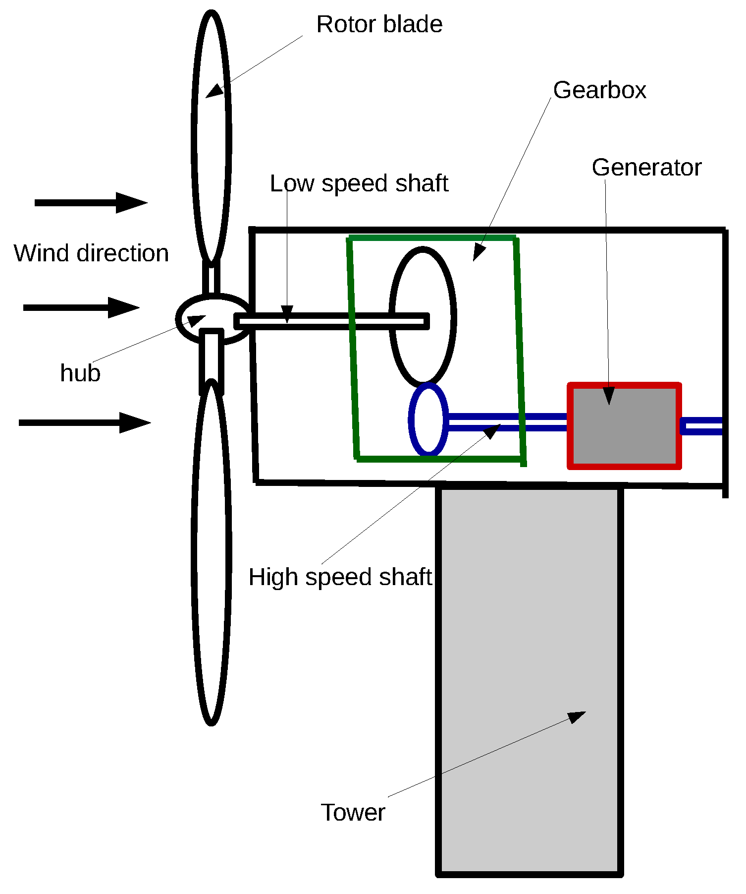
1.1. Background
1.2. Literature Survey
1.3. Contribution of This Study
1.4. Organization of the Paper
2. Methods
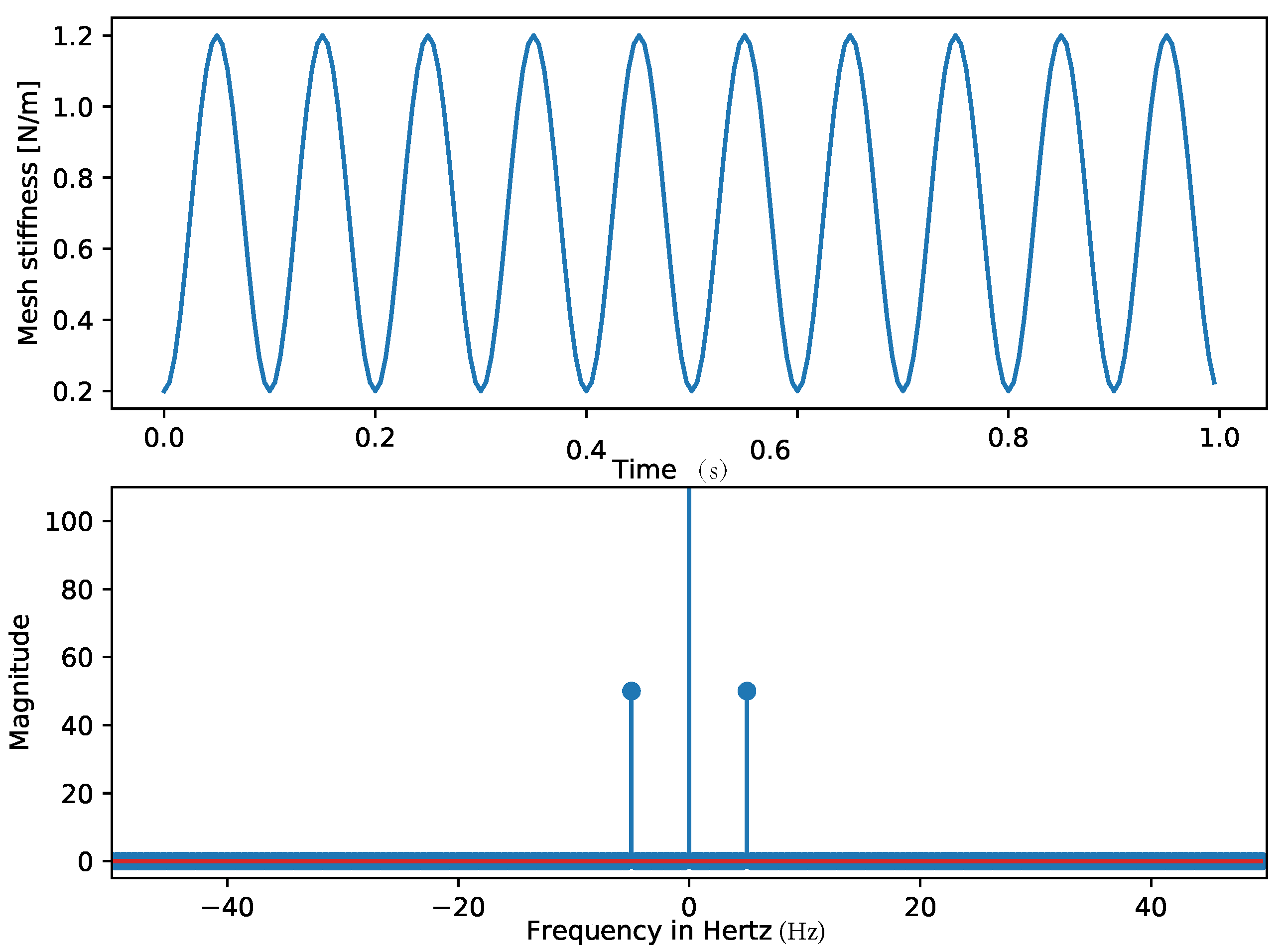
2.1. Mesh Stiffness
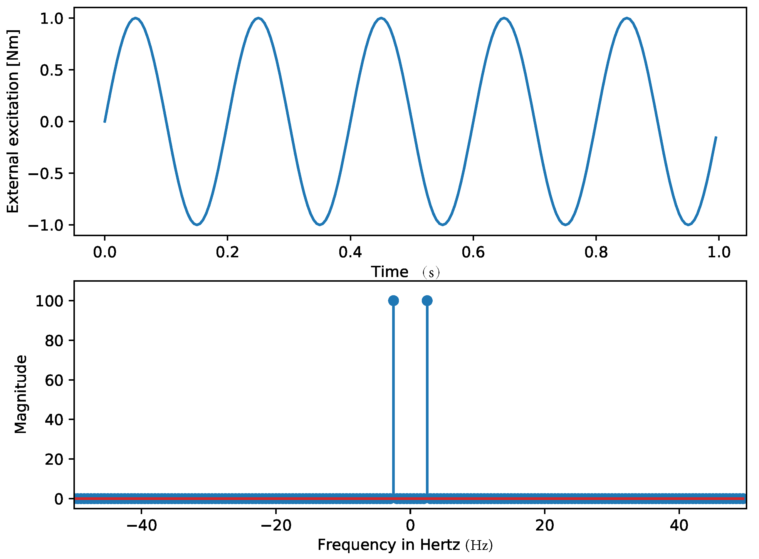
2.2. External Excitation
2.3. Generator Torque Equation
2.4. Backlash Equation
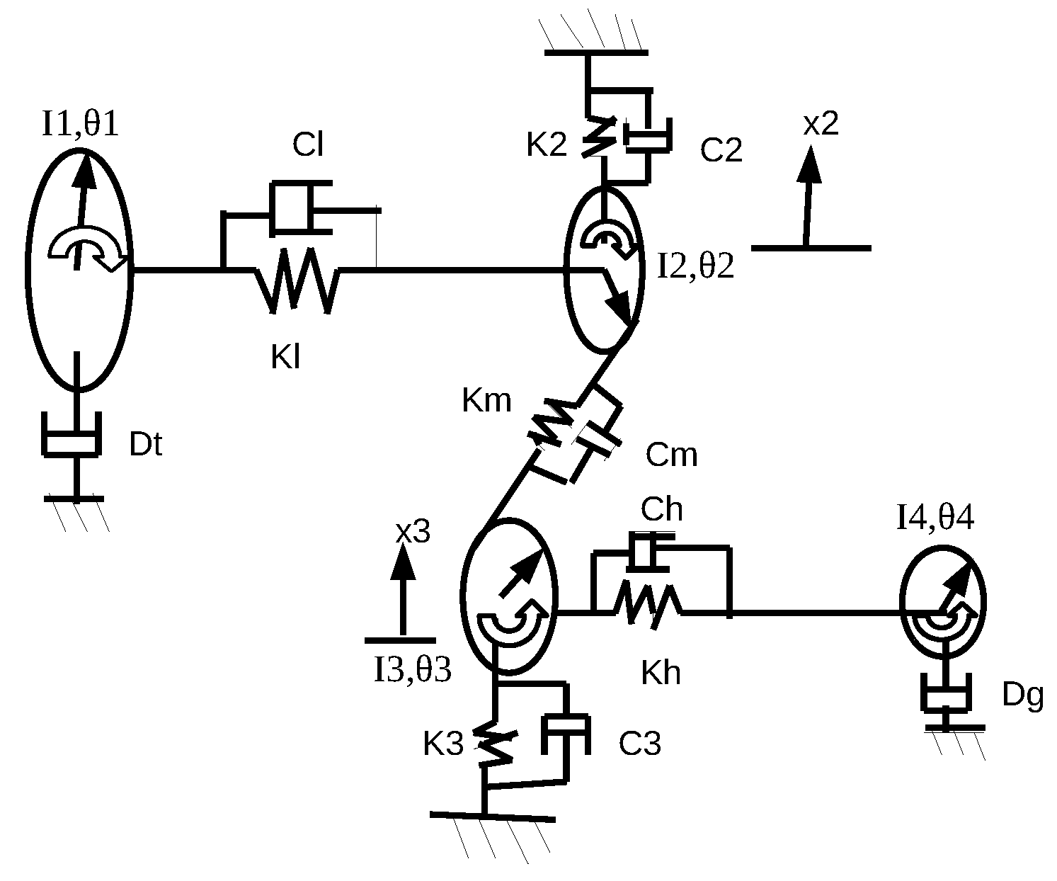
2.5. Rotational Equations of Motion
2.6. Equations for Axial Vibrations
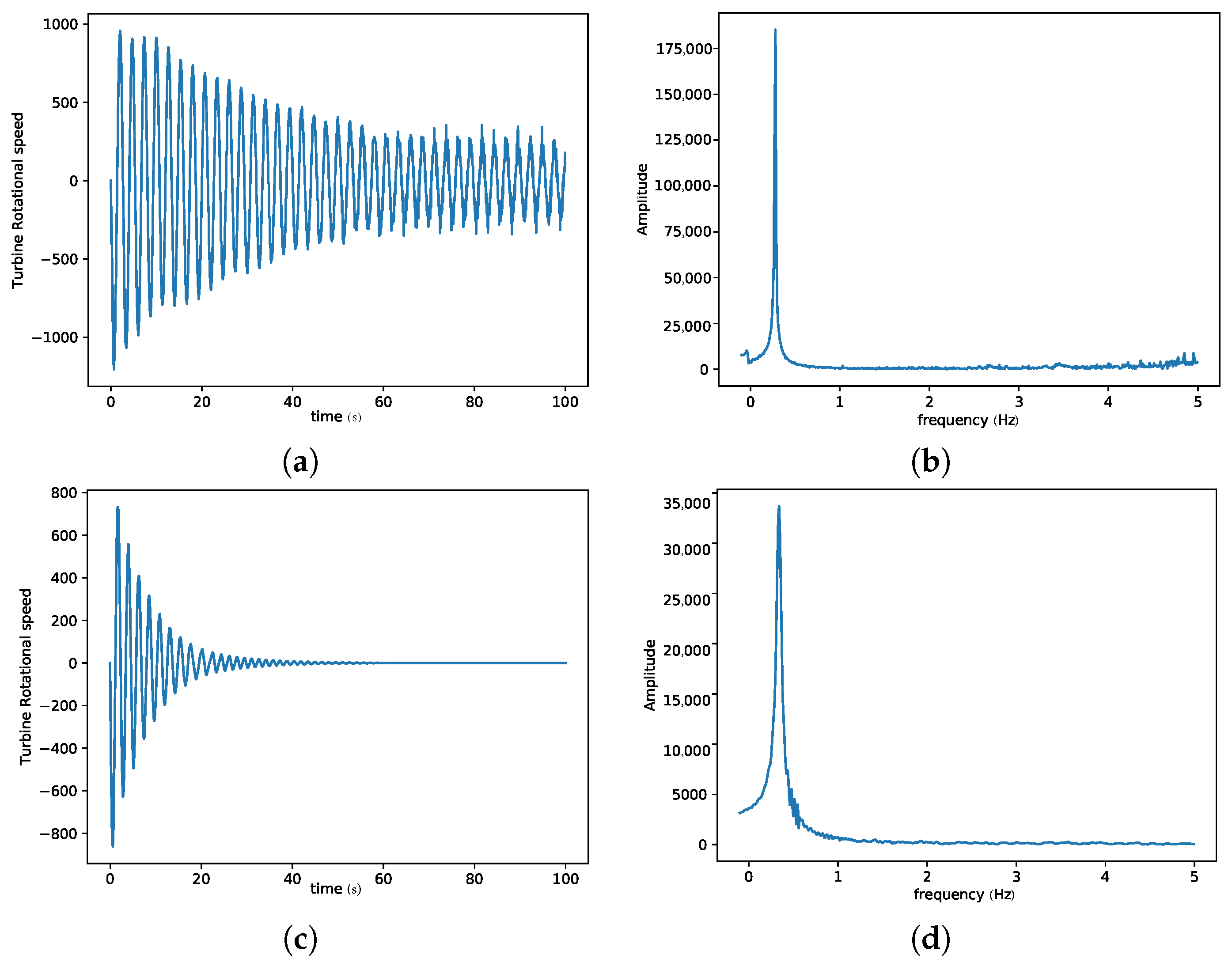
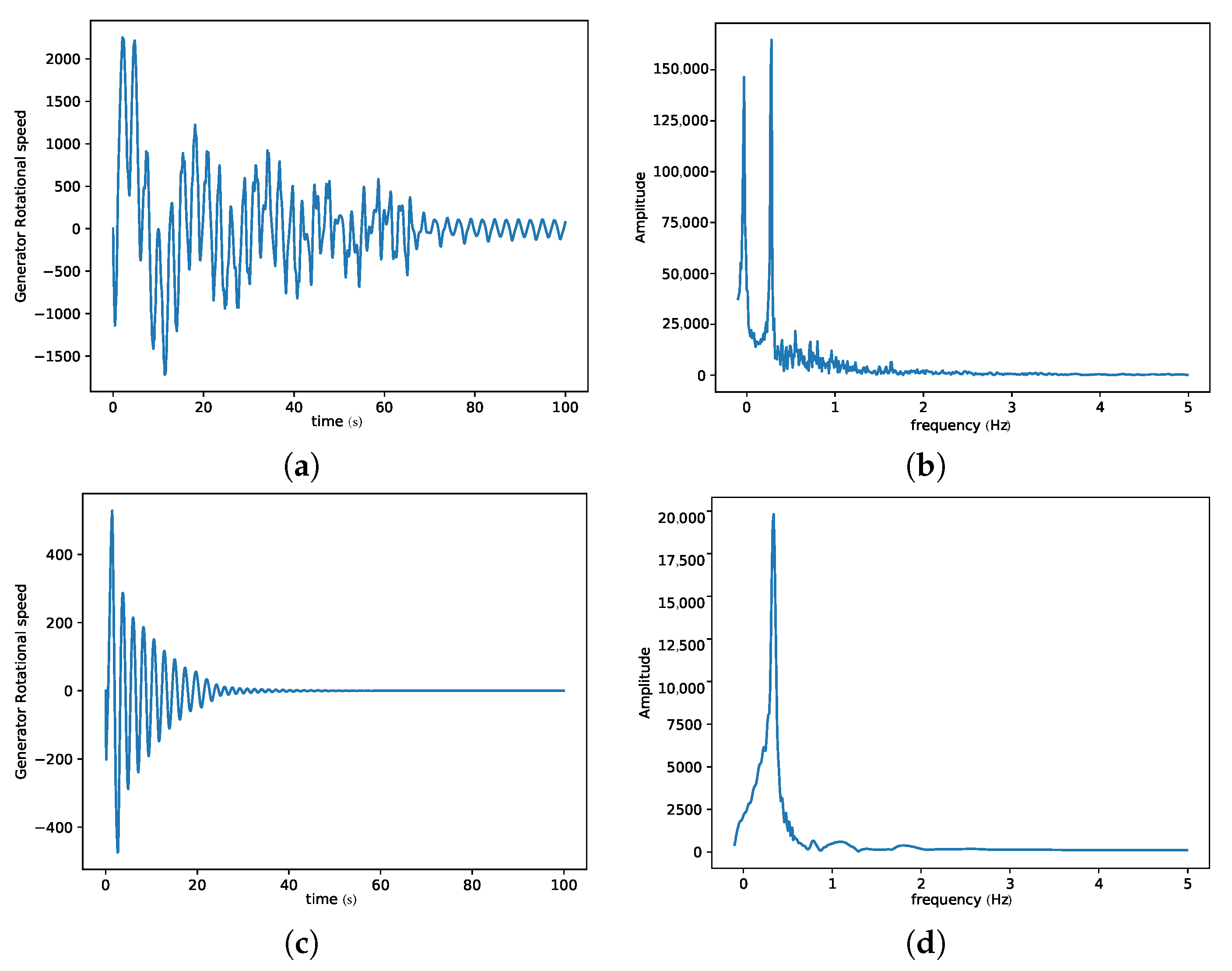
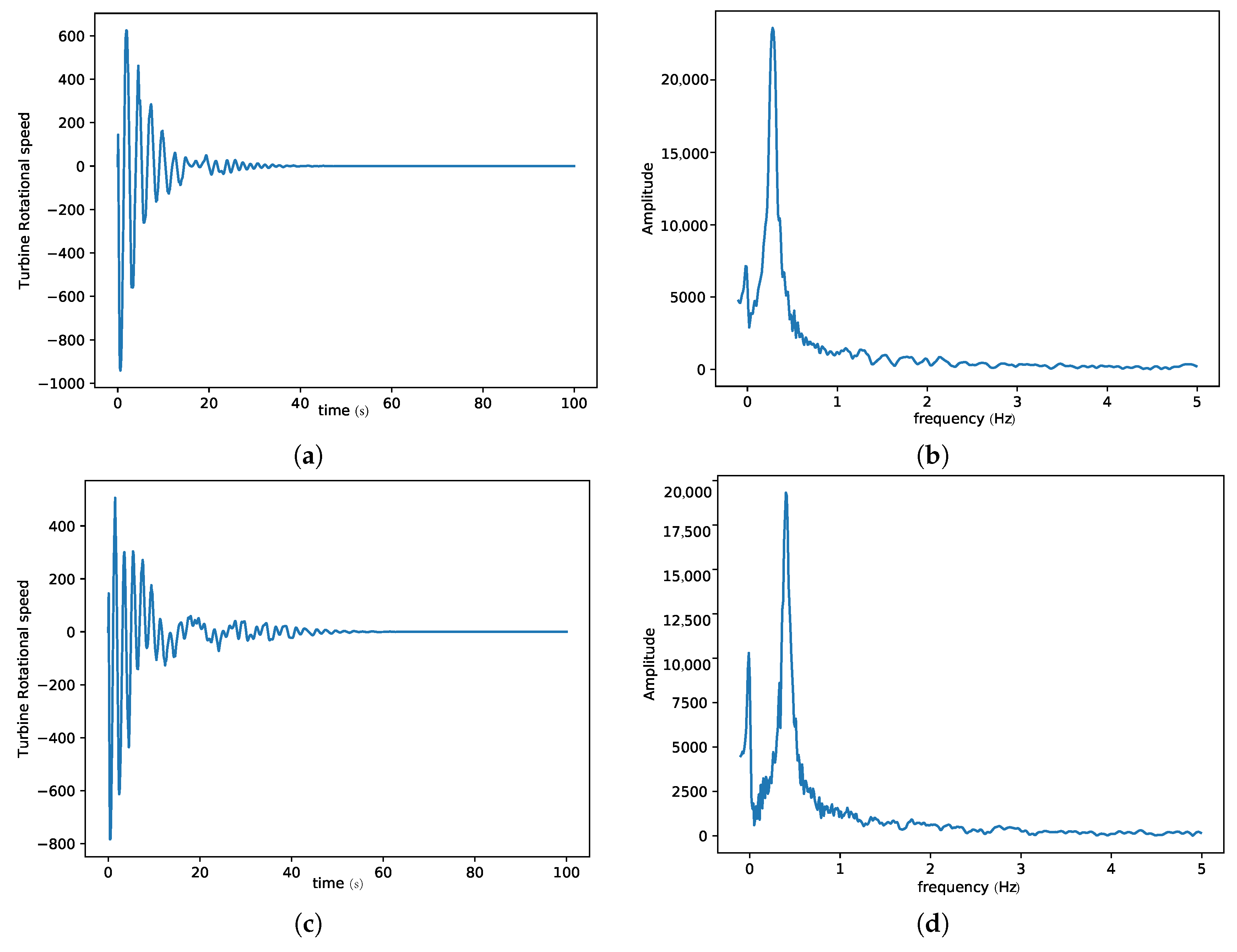
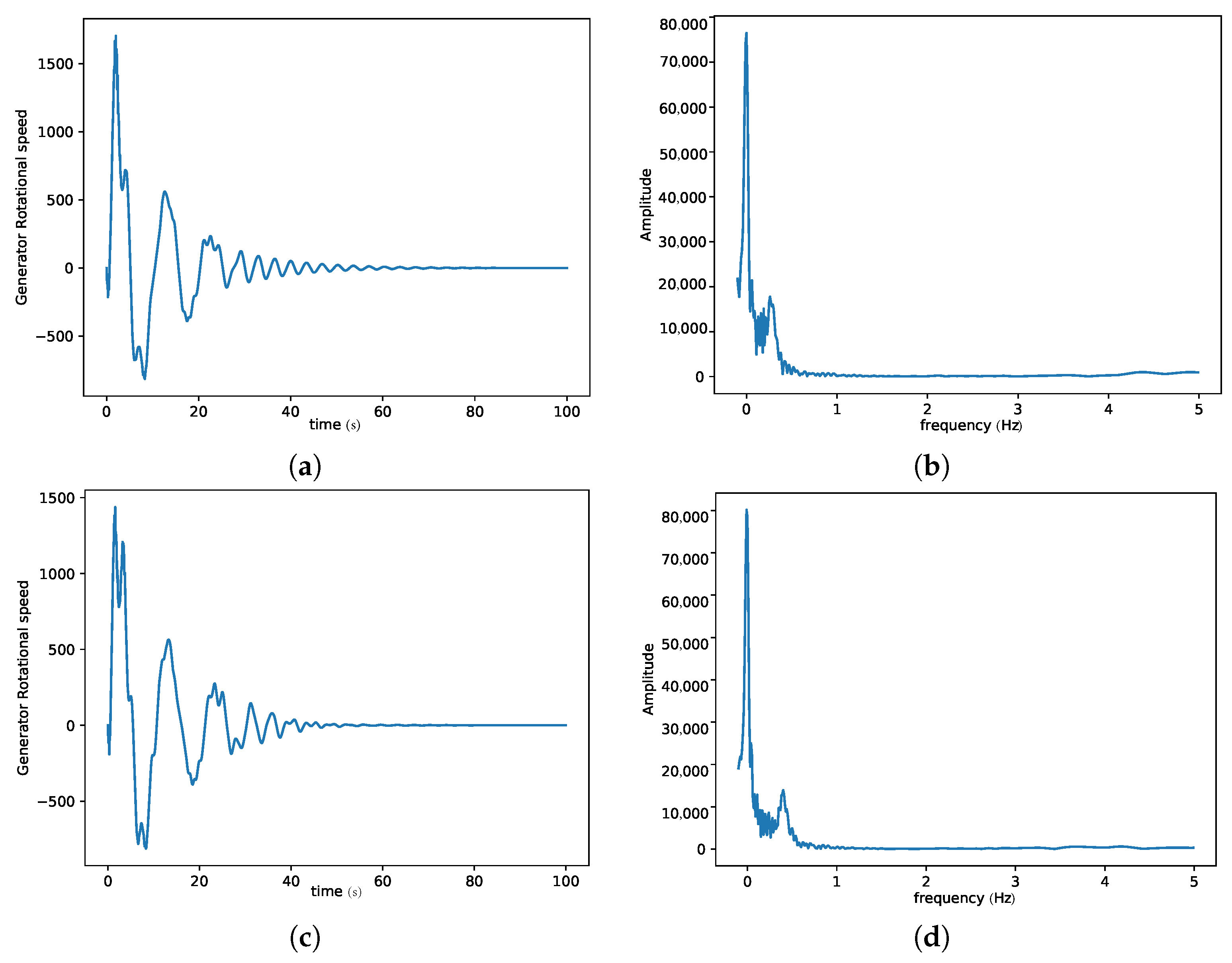
3. Results and Discussion
4. Conclusions
5. Future Work
Acknowledgments
Author Contributions
Conflicts of Interest
Abbreviations
| , | the turbine and generator torques |
| the moment of inertia of the wheels | |
| the masses of the wheels | |
| the angular positions of the wheels | |
| , , , | the low speed shaft torsional stiffness, high speed shaft torsional stiffness |
| and bearing stiffness for Gear 1 and Gear 2, respectively | |
| , , , | the low speed shaft damping, high speed shaft damping |
| and bearing damping for Gear 1 and Gear 2, respectively | |
| the helical or pressure angle | |
| and | the mesh damping and stiffness, respectively |
| RK4 | Runge-Kutta of order 4 |
References
- Perdana, A. Dynamic Models of Wind Turbines. A Contribution towards the Establishment of Standardized Models of Wind Turbines for Power System Stability Studies; Avancez: Goteborg, Sweden, 2008; pp. 29–32. ISBN 978-91-7385-226-5. [Google Scholar]
- Wasynczuk, O.; Man, D.; Sullivan, J. Dynamic behavior of a class of wind turbine generators during random wind fluctuations. IEEE Trans. Power Syst. Appar. Syst. 1981, PAS-100, 2837–2845. [Google Scholar] [CrossRef]
- Hinrichsen, E.; Nolan, P. Dynamics and stability of wind turbine genera- tors. IEEE Trans. Power Appar. Syst. 1982, 101, 2640–2648. [Google Scholar] [CrossRef]
- Zhao, M.; Ji, J.C. Nonlinear torsional vibrations of a wind turbine gearbox. Appl. Math. Modell. 2015, 39, 4928–4950. [Google Scholar] [CrossRef]
- Zhao, M.; Ji, J. Dynamic Analysis of Wind Turbine Gearbox Components. Energies 2016, 9, 110. [Google Scholar] [CrossRef]
- Yang, F.; Shi, Z.; Meng, J. Nonlinear dynamics and load sharing of double-mesh helical gear train. J. Eng. Sci. Technol. Rev. 2013, 6, 29–34. [Google Scholar]
- Helsen, J.; Vanhollebeke, F.; Marrant, B.; Vandepitte, D.; Desmet, W. Multibody modeling of varying complexity for modal behavior analysis of wind turbine gearboxes. Renew. Energy 2011, 36, 3098–3113. [Google Scholar] [CrossRef]
- Heege, A.; Betran, J.; Radovcic, Y. Fatigue load computation of wind turbine gearboxes by coupled finite element, multi-body system and aerodynamic analysis. Wind Energy 2007, 10, 395–413. [Google Scholar] [CrossRef]
- Zhao, X.; Maißer, P.; Wu, J. A new multibody modeling methodology for wind turbine structures using a cardanic joint beam element. Renew. Energy 2007, 32, 532–546. [Google Scholar] [CrossRef]
- Kim, T.; Hansen, A.M.; Branner, K. Development of an anisotropic beam finite element for composite wind turbine blades in multibody system. Renew. Energy 2013, 59, 172–183. [Google Scholar] [CrossRef] [Green Version]
- Pappalardo, C.M. A natural absolute coordinate formulation for the kinematic and dynamic analysis of rigid multibody systems. Nonlinear Dyn. 2015, 81, 1841–1869. [Google Scholar] [CrossRef]
- Pappalardo, C.M.; Guida, D. On the use of two-dimensional Euler parameters for the dynamic simulation of planar rigid multibody systems. Arch. Appl. Mech. 2017, 87, 1647–1665. [Google Scholar] [CrossRef]
- Girsang, I.P.; Dhupia, J.S.; Eduard, M.; Mohit, S. Gearbox and Drivetrain Models to Study Dynamic Effects of Modern Wind Turbines. National Renewable Energy Laboratory (NREL). Available online: www.nrel.gov/publications (accessed on 28 February 2018).
- Parker, R.G.; Lin, J. Mesh phasing relationships in planetary and epicyclic gears. J. Mech. Des. 2004, 126, 365–370. [Google Scholar] [CrossRef]
- Masters, G.M. Renewable and Efficient Electric Power Systems; John Wiley & Sons: Hoboken, NJ, USA, 2005. [Google Scholar]


| Name | |
|---|---|
| Parameters | Values |
| Inertia (Kgm2) | |
| mass | |
| Radius | , |
| Pressure angle | |
| Torsional stiffness | , , |
| Damping | |
| , , | |
| , | |
| , , | |
| Torque | , |
| Excitation frequencies | , |
© 2018 by the authors. Licensee MDPI, Basel, Switzerland. This article is an open access article distributed under the terms and conditions of the Creative Commons Attribution (CC BY) license (http://creativecommons.org/licenses/by/4.0/).
Share and Cite
Ayuketang Arreyndip, N.; Moise Dikande, A.; Joseph, E. Nonlinear Multi-Frequency Dynamics of Wind Turbine Components with a Single-Mesh Helical Gear Train. Math. Comput. Appl. 2018, 23, 12. https://0-doi-org.brum.beds.ac.uk/10.3390/mca23010012
Ayuketang Arreyndip N, Moise Dikande A, Joseph E. Nonlinear Multi-Frequency Dynamics of Wind Turbine Components with a Single-Mesh Helical Gear Train. Mathematical and Computational Applications. 2018; 23(1):12. https://0-doi-org.brum.beds.ac.uk/10.3390/mca23010012
Chicago/Turabian StyleAyuketang Arreyndip, Nkongho, Alain Moise Dikande, and Ebobenow Joseph. 2018. "Nonlinear Multi-Frequency Dynamics of Wind Turbine Components with a Single-Mesh Helical Gear Train" Mathematical and Computational Applications 23, no. 1: 12. https://0-doi-org.brum.beds.ac.uk/10.3390/mca23010012