Sensorless Speed Tracking of a Brushless DC Motor Using a Neural Network


1
División de Estudios de Posgrado, Universidad Tecnológica de la Mixteca, Carretera a Acatlima Km 2.5, Huajuapan de León 69000, Oaxaca, Mexico
2
División de Ingenierías, Campus Irapuato-Salamanca, Universidad de Guanajuato, Carr. Salamanca-Valle km 3.5+1.8, Comunidad de Palo Blanco, Salamanca 36700, Guanajuato, Mexico
*
Author to whom correspondence should be addressed.
Math. Comput. Appl. 2020, 25(3), 57; https://0-doi-org.brum.beds.ac.uk/10.3390/mca25030057
Submission received: 30 July 2020
/
Revised: 2 September 2020
/
Accepted: 2 September 2020
/
Published: 4 September 2020
(This article belongs to the Special Issue Advanced Mathematics and Computational Applications in Control Systems Engineering)
Abstract
:In this work, the sensorless speed control of a brushless direct current motor utilizing a neural network is presented. This control is done using a two-layer neural network that uses the backpropagation algorithm for training. The values provided by a Proportional, Integral, and Derivative (PID) control to this type of motor are used to train the network. From this PID control, the velocity values and their corresponding signal control (u) are recovered for different values of load pairs. Five different values of load pairs were used to consider the entire working range of the motor to be controlled. After carrying out the training, it was observed that the proposed network could hold constant load pairs, as well as variables. Several tests were carried out at the simulation level, which showed that control based on neural networks is robust. Finally, it is worth mentioning that this control strategy can be realized without the need for a speed sensor.
1. Introduction
Nowadays, Brushless direct current (BLDC) Motors are extensively used because of their characteristics. Such characteristics are high dynamic response and high-power density. Usually, these kinds of motors are controlled employing an electronic inverter of commutation composed of three-phases. Typically for controlling these types of motors, a six-step commutation and a three-phase voltage source inverter are used, where the commutation of the inverter components is determined by the state of the Hall effect sensors. In recent years, works have been reported for speed control in this type of engine based on this scheme; such is the case of the work presented by Zhao et al. [1].
There have been considerable efforts in solving the soft computing approach to control brushless motors. The work developed by Shanmugasundram et al. [2] presents a comparison of control for a brushless motor using PID, fuzzy logic, and a hybrid of neural networks which show the effectiveness of these controllers such as speed response, steady-state error, among others. Arulmozhiyal and Kandiban [3] made a fuzzy PID controller in which they present the facility to tune the PID constants using the implemented fuzzy system. For their part, Premkumar and Manikandan developed a diffuse neuro controller, which had a higher performance than the other implementations tested [4]. In [5], Al-Maliki and Iqbal have also used a fuzzy Logic Control, but this time for tuning a PID controller. In addition, Mamadapur and Mahadev [6] implemented a PID for speed control of a BLDC motor but using Neural networks.
For their part, Liu et al. [7] developed a control strategy for these types of motors that consisted of the implementation of control through an adaptive neural network for current monitoring in this system. Ibrahim et al. [8] made a comparison between the Particle Swarm Optimization techniques and the bacterial food search technique to determine the optimal parameters of a PID speed controller for a BLDC motor. In [9], an adaptive fuzzy logic for speed control of a BLDC motor was developed using ANN and PSO techniques. Potnuru et al. [10] used a pollination algorithm for speed control of a BLDC motor. Another work that implements a speed control for a BLDC motor can be found in [11], where an adaptive neural network with a fuzzy inference core was used. Templos-Santos et al. have used bio-inspired algorithms in order for parameter tuning of a PI controller in a Permanent magnet synchronous motor (PMSM) [12]. Merugumalla and Kumar [13] used the firefly algorithm to create a motor drive of speed control for a BLDC. One last work is that developed by ELkholy and El-Hay [14], and they have evaluated the efficient dynamic performance of BLDC motor using different soft computing approaches. It is worth mentioning that the works mentioned above use a sensing mechanism to give feedback to the control system, making this more elaborate and, in some cases, more costly to implement these methods.
More focused works concerning the control of direct current motors, beginning with the work of Yu et al. [15], who used a neural network to carry out adaptive control in a PMSM. For their part, Cheng et al. [16] made use of a radial neural network for the control of a brushless DC motor with excellent results. The fusion of neural networks with a diffuse system was presented by Abed et al. [17] to diagnose failures in the bearings of a BLDC engine. In [18], Luo et al. performed the control of a brushless motor using the adaptive dynamic surface control technique modeled by a neural network. Saleh et al. [19] used wavelet neural networks to implement a speed controller for a BLDC motor. Naung et al. [20] adjusted the parameters of a controller PI to control the speed of a BLDC motor through a neural network. In [21], Dynamic Neural Networks were used to develop an intelligent control for a BLDC Motor. Finally, let us mention the work of Ho et al., who implemented a driver for a DC motor through the use of neural networks [22].
In this paper, the main motivation to study the sensorless control of a BLDC motor is the use of neural networks.The above is due to the neural networks are a better way to recognize patterns from the sample of the system which going to be controlled. Therefore, when the control of a BLDC motor wants to be made, usually, the use of observators is necessary in order to estimate, mainly, the position of the motor. These observators replace the use of sensors but are very complicated to implement. For this reason, the use of any sensorless techniques for control or estimation of the parameters of the motor. For example, in [23], the five-phase induction of the motor was modeled by means of the short-circuit fault between turns and sensorless control strategy. In [24], König, Nienhaus, and Grassohave analyzed and modeled the current ripples generated by electromagnetic actuators to estimate the inductance and carry out sensorless monitoring of the device. On the other hand, Che et al. [25] implemented a sensorless speed control for an induction motor using the sliding modes method and genetic algorithms. Another kind of motor where the sensorless technique was used is the Permanent magnet synchronous motor. In the work of Wu and Zhang [26], sensorless speed control was developed for a PMSM using terminal sliding mode and backstepping. In [27], Aguilar et al. implemented a sensorless speed tracking controller for a PMSM based on a second-order sliding mode observer and tested with load variations. Meanwhile, Kivanc and Ozturk have developed a position sensorless speed control for PMSM by means of a space vector based on four switches and three phases inverter [28]. In [29,30], interesting studies about sensorless control of PMSM are presented using estimation methods and sliding mode observer.
Next, a couple of works where the sensorless and neural networks are combined will be mentioned. One of them is [31], where a sensorless speed system was implemented based on the reactive power-based model reference adaptive system speed estimator and adaptive neural network for a PMSM. In [32], a neural network was used for a sensorless control for a PMSM oriented tor wind energy conversion.
On the side of the BLDC motor, Sreeram [33] implemented a speed regulation control of a sensorless BLDC utilizing fuzzy logic and four-switch three-phase inverter. The development presented in [34], where the radial displacement of the stator is proposed as a mechanism to improve speed control for a BLDC drive in a sensorless way. In [35], Vanchinathan and Valluvan used the Bat algorithm to control in a sensorless way the rotor speed of the BLDC motor. A study comparative of different controller techniques is presented in [36], where a controller PI, an anti-windup PI, a fuzzy logic-based, and a fuzzy controller PI are compared to validate the performance of sensorless BLDC motor at different loads and speeds. Rif’an, Yusivar, and Kusumoputrohave proposed the use of the ensemble Kalman filter (EnKF) and neural networks to predict load changes and estimates of the disturbance by simulation of a sensorless BLDC [37].
Finally, other works that made use of non-invasive methods for sensing some physical variable or detect failures in motors will be next mentioned. In [38], the technique of Signal Analysis based on Chaos using Density of Maxima(SAC-DM) technique was applied in the diagnosis of failures of BLDC motors from sound signals. In addition, Medeiros et al. [39] used the SAC-DM to detect failures in BLDC motors. Meanwhile, other works are focused on detecting faults in induction motors based on the analysis of acoustic sound and vibration signals [40,41,42].
For this reason, in this work, the controlling brushless DC motor through neural networks and without the need for sensing is proposed. Solving this kind of problem is essential since it is not always easy to have a sensor for the different internal parameters of a motor in order to control such parameters, especially for a BLDC driver. In addition, the neural network utilized to solve the controller of this motor is implemented only with two-layer; then, the neural network is simple and easy to port into embedded hardware to generate a non-dependent computer system.
In order to show a generalized idea of the advantages of our implementation, the highlights of our work will be listed below:
- (i)
- A sensorless velocity control was developed through a neural network of the type multi-layer perceptron architecture.
- (ii)
- The neural network implemented has only two layers. This means that the network is the smallest of such used in the majority of the papers.
- (iii)
- The training set used is formed of just 22 values being that there are 5000 example data extracted from the curves used for training.
- (iv)
- The use of a neural network applied to the control of a motor avoids the use of a sensor.
The main novelty of our approach is found in the third item of the advantages previously presented, due to the vast majority of works about this topic and that use a neural network utilizing a big number of examples to train the neural network.
The implementation and the results obtained in various tests carried out are presented in the following sections—starting with Section 2, where the typical structure for brushless motor control is shown as well as its simulation in the PSIM software [43]. In addition, in Section 2, a brief review of the neural network and its architecture used is presented. The implementation of motor control and the training of the neural network are described in Section 3. Section 4 shows the tests and results of the motor control implementation through the neural network. Additionally, a comparison against the PID control is made in Section 4, too. In order to clarify some points about the results obtained in this work a discussion was added in Section 5. Finally, the conclusions of this work, as well as perspectives for its continuation, are presented in Section 6.
2. Materials and Methods
This section presents and explains the different methods and materials used to achieve the results in this paper. First, it is necessary to present a brief description of the brushless direct current just to contextualize the functioning of the motor. In the second part of this section, a general revision about the concepts of neural networks will be presented.
2.1. Motor Brushless
A brushless motor is an electric motor controlled by an electrical signal. This type of motor lacks any form of collector or sliding ring. The motor requires some form of alternating current to rotate, either from an alternating current (AC) power supply or an electronic circuit. These motors have certain advantages over brushed motors, which are ideal for robotics projects. Some advantages and disadvantages of this type of motors are presented below:
Advantages:
- (a)
- Higher efficiency (less heat loss)
- (b)
- Higher performance (longer battery life for the same power)
- (c)
- Less weight for the same power
- (d)
- They require less maintenance since they do not have brushes
- (e)
- Speed/torque ratio is almost a constant
- (f)
- Higher power for the same size
- (g)
- Better heat dissipation
- (h)
- High speed range without mechanical limitation.
- (i)
- Less electronic noise
Disadvantages:
- (a)
- Higher construction cost
- (b)
- Control is through an expensive and sophisticated circuit
- (c)
- It always takes an electronic control to work (ESC’s), which sometimes doubles the cost.
The BLDC motor uses a DC power supply applied by power devices, and the position of the rotor determines its switching sequence. The BLDC motor phase current, which has a rectangular waveform, must be synchronized with the rear counter electromotive force (EMF) to produce a constant torque at a constant speed. Electronic power switches replace the conventional mechanical switch, and the current of the motor windings is supplied depending on the position of the rotor. This type of AC motor is called a brushless DC motor, and its operation is similar to that of conventional DC motors with a switch.
BLDC motors are generally controlled employing three-phase inverters, so it requires a rotor position sensor to control the inverter in order to determine the switching instants and provide an appropriate sequence for switching. The position of the motor in these engines is generally determined by position sensors such as Hall effect sensors, resolvers, and absolute position sensors; otherwise, it must be prepared by estimating the parameters that specify the rotor position using sensorless techniques [44,45].
The driving range for each phase is usually 120 electrical degrees, which is divided into two 60-degree steps. For example, S5-S6, S1-S6, S1-S2, S3-S2, S3-S4, and S5-S4 are six steps of a 360-degree electric cycle. Therefore, only two phases are carried out at a time. The above can be seen graphically in Figure 1.
From the operation of the engine and their elements, the BLDC engine is modeled to simulate its behavior. The brushless motor model implemented in the PSIM simulation environment is shown in Figure 2. This figure shows the three-phase inverter, which has a sensor to monitor the current supplied to the BLDC. It is also possible to see that the BLDC motor is coupled with a sensor for speed reading. This sensor generates the control signal that determines the pulse width of the PWM (Pulse Width Modulation) that activates each of the inverter’s drivers, in addition to the necessary switching stage that depends on the state of the Hall effect sensors. This switching allows the three-phase inverter to function normally in addition to preventing a short circuit in any of the three branches.
2.2. Neuronal Networks
For artificial intelligence, neural networks are a significant field of application. These are inspired by the interconnections of the cells of the human brain. In addition, they try to simulate the behavior of a biological neural network. Thus, neural networks are usually used to model systems that solve difficult problems through other techniques.
Some examples where artificial neural networks have been used to solve various tasks such as pattern recognition [46], parameter estimation [47], prediction of values [48] and of course in the control of different types of systems [49,50,51].
In general, a neural network is formed by the next elements:
- Neurons
- Layer
- Transfer functions
- Weights
Usually, the neural networks have several layers composed of a different number of neurons each of them. In general, neural networks are composed of three different layers: input, hidden, and output. The information goes from one layer to another through the transfer functions. The transfer function determines how the information is transmitted between layers. Weights are directly associated with the connection between layers. That is, if a connection has weight with a high value, then it will make more contributions to the network output.
One of the most used neural networks is called multi-layer perceptron, and the best-known training method for this type of network is backpropagation. This algorithm is used more for learning this kind of multi-layer perceptron network. The backpropagation algorithm trains the neural network from sample vectors of the system that are of interest for their modeling, such as the texture of an object or, in our case, the speed of a motor.
Summarizing, the backpropagation training system consists of the following steps:
- Initialize the weights of the network randomly.
- Enter input data from among those to be used for training.
- Let the network generate an output data vector (forward propagation).
- Compare the network output with the desired output.
- The difference between the generated and the desired output (called error) is used to adjust the weights in the output layer.
- The error spreads backwards (hence the name of backpropagation), towards the previous neuron layer, and is used to adjust the weights of that layer.
- Continue propagating the error backwards and adjusting the weights until the input layer is reached.
One of the advantages that backpropagation presents is a speed of convergence and robustness compared to other types of training. For this reason, in this work, a multi-layer perceptron neuronal network has been implemented using backpropagation as a training algorithm. This network was used for speed control of a brushless motor. The architecture of the neural network used for the development of this work has a topology 2:8:1 and uses only two layers. The relation 2:8:1 means that the neural network has an input vector of a size of two elements. This means that every example presented to the neural network only has two elements. The second number 8 belongs to the number of neurons that have the first hidden layer. Finally, number 1 tells us that there is only one neuron in the output layer.
As it is possible to see, the neural network needs only two layers of neurons in order to obtain an excellent performance of the control system proposed. However, just with this configuration, the neural network is capable of learning the vectors related to brushless motor control.
Part of the neural network training will be addressed in the next section.
3. Neural Network Training
As previously noted, it is necessary to have example vectors related to the problem to be solved by the neural network. These sample vectors must come from real examples of the objects or the system to be modeled. In this case, examples of the motor’s response to different applied torques are required.
For this reason, a classical Proportional, Integral, and Derivative (PID) controller has been implemented in order to obtain previous test values to train the proposed network. Figure 3 shows the block diagram of the PID controller used. This figure consists of a DC/AC converter, usually called a voltage inverter. This inverter supplies the three-phase voltages for the BLDC motor. The applied load torque, the sensing of the rotor speed, a reference speed block that will serve for the training of the network, the PID control, and the inverter switching stage determined by the states of the Hall effect sensors are detailed in Figure 2.
From the PID control shown in the diagram in Figure 3, the different values for the input vectors of our neural network are obtained.
Figure 4 shows the training signal made to the BLDC motor with the PID control. This signal must follow the desired reference that starts from scratch and increases its speed smoothly to 750 rpm (revolutions per minute). It is worth mentioning that the value of 750 rpm is the maximum speed that the motor can reach. In the same figure (Figure 4), it is possible to observe the signal resultant, which was obtained with no external load pair applied to the system. For this reason, it will be mentioned as a zero pair in future mentions of it. In order to have greater control over the gains of the PID controller, they were chosen heuristically. Hence, the chosen earnings were and for , , and , respectively. From this test, pairs of velocity values and the control signal necessary to reach the velocity values for each pair are taken. These values are sampled every 40 rpm; therefore, 600 input vectors will be used as examples for the neural network. These values will serve to train our neural network so that it is capable of controlling the motor with zero torque.
Figure 5 graphically shows the 22 values obtained from the zero torque PID control tests that will be used to train the neural network. It is worth mentioning that, within the sample pairs used, the minimum and maximum values are included, which are 0 and 800 rpm, respectively.
Obtaining the previous values, as can be seen in the previous paragraphs, is only to train the neural network when the motor does not have an applied load, that is, when the torque is zero. Therefore, to determine the behavior of the network when a non-zero torque is applied, it is necessary to train the network with different load values.
As it was required to have the performance of the neural network in a range of 0 to 1 Nm, it was considered to train the network with load pairs applied in the said range in increments of 0.25 Nm.
To obtain the input vectors for each of the different load pairs to be learned by the network, the same procedure is performed as for obtaining the vectors with zero torque. Obviously, this time the network is trained with the desired speed values, control signal, and applied torque for each applied torque from 0 to 1 Nm in increments of 0.25 Nm.
Some values obtained for each of the different applied load pairs are observed in Figure 6. These values are used to train the network that can control the BLDC system when any load pair is applied.
This will allow the neural network to have a dynamic performance when applying a load in the range of 0 to 1 Nm. Although the network will train only with well-defined load values every 0.25 Nm, it will be able to infer the performance that it should have in the desired speed values that were never presented to the system.
Like any control system, it is necessary to determine the parameters with which the controller will work. Unlike a PID controller, a neural network does not require that these values be modified every time any element of the system changes. This is another advantage of using a neural network compared to classical control methods. This is because the network adapts to resolve cases that were not presented during training. It should be mentioned that this only happens within the logical ranges of the expected behavior of the system.
In this case, the parameters of the neural network and its training are presented in Table 1.
Some observations regarding the values shown in Table 1. First, it will be mentioned that, although the neural network training indeed used the backpropagation algorithm, this algorithm has four variants. These variants are listed below:
- Momentum,
- Variable learning ratio,
- Conjugate gradient, and
- Levenberg–Marquardt.
Being the Levenberg–Marquardt algorithm, the backpropagation variant with which, generally, better performance is obtained in the tasks assigned to the neural network. For this reason, in this implementation, it was decided to use this variant. Although this variant indeed has the highest computational cost, it is compensated by the excellent performance it offers.
Another observation regards the number of epochs that were specified as the maximum value in this implementation. In general, for a neural network to converge towards the optimal values of the weights, 1000 to 10,000 epochs are required. For this reason, this parameter began to carry out tests from 5000 epochs. However, in the different experiments made, it was observed that the neural network had a convergence in a range of 18 to 50 epochs. The last-mentioned means that training does not take a long time of 50 epoch to obtain a result. Then, this parameter was established in 50 as a maximum value that training needed to reach the optimal values of the weights.
The above is due in part to three main things. One of them is the use of the Levenberg–Marquardt algorithm for training, which has a faster convergence towards the optimal values of the network weights even if it requires more processing to get convergence of the network. The other is the number of network layers, which, in our case, only have the input and output layers.
Finally, the number of neurons is mentioned; in our implementation, only nine neurons are necessary. Eight of these neurons are in the input layer, while the output layer only has one neuron.
It is important to emphasize that our implementation occupies few neurons, as previously mentioned. This is a feature that will allow us to implement this controller quickly and efficiently in an embedded system, such as an FPGA [52]. It would even be possible to implement it on a lower-performance device such as an Arduino. The above would give portability to this controller, thus obtaining a lower-cost hardware implementation.
Once the implementation of the brushless motor controller through neural networks is presented, the results obtained are shown. Therefore, in the following section, both the tests performed and the results obtained from this implementation will be presented.
4. Results
This section presents the different tests carried out on the implementation of the control performed with the neural network as well as the comparison against the control carried out by the PID. It will begin with the performance of the control performed by the neural network when there is no load applied to the plant.
The different tests and results were developed using the Matlab/Simulink-PSIM package. For this, the BLDC model SG/F14 Gearless motor parameters were used. Parameters mentioned were obtained by characterizing it and used in the PSIM simulation environment. These values are shown in Table 2.
Figure 7 shows the block diagram of the plant which is made up of the following elements:
- A three-phase BLDC motor
- A mechanical load
- A Voltage Source Inverter (VSI)
- A current sensor (to measure the direct current () consumed by the inverter)
- A PWM device (with a frequency of 10 kHz)
- The path speed reference
- The neural network implemented in Matlab/Simulink.
On the other hand, Figure 8 shows the diagram of the implementation of the neural network made in Matlab/Simulink. In this diagram, the stage that defines the desired path, the applied load torque, as well as the implemented neural network and the BLDC motor system can be seen, shown above in Figure 2.
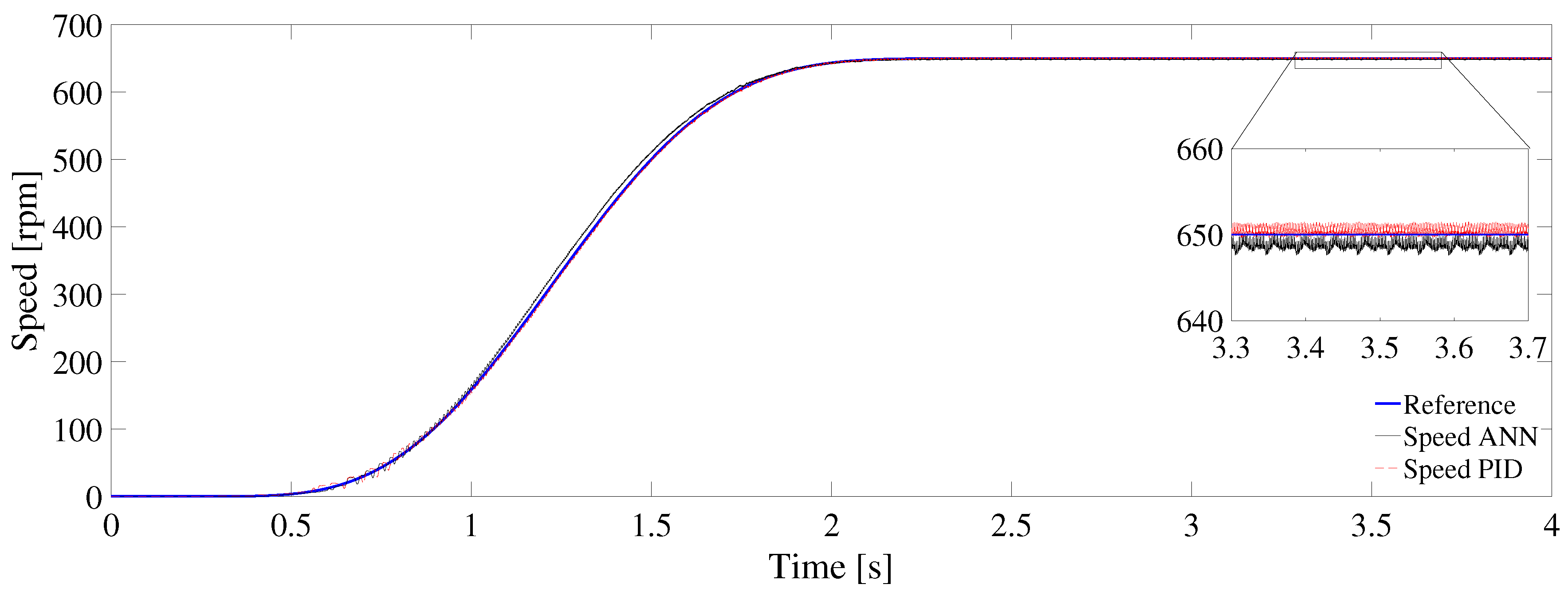
It will start with the performance of the control performed by the neural network when there is no load applied to the plant. The behavior of the trained network can be seen in Figure 9. In this test, the neural network is subjected to following a desired speed reference path from zero to 650 rpm. It should be mentioned that this was not a network training value. However, the fact of training without a load applied to the plant was to have a reference value for later comparison with variable load.
Furthermore, in this same figure, it can be observed the comparison of the control signals of both the network and the PID control. This comparison shows that both velocity signals are very similar, but the neural network remains around the desired reference. With this, it is shown that the scheme of the proposed network is functional.
The behavior of the implemented neural network control signals compared to that of the PID is shown in Figure 10. In this figure, it can be seen that the two responses to the desired velocity values are very similar.
In the same Figure 10, a satisfactory behavior of the neural network is observed both in the speed error obtained and the current required by the inverter. Analyzing the system error and leaving aside the part of the transient. In this case, it can be seen that the neural network has a much smaller error than that obtained by the controller through the PID; furthermore, the neural network is maintained around the desired reference.
On the side of the current required by the inverse, it can be seen that the one required with the control of the neural network is more stable and constant, unlike the requirement of the PID.
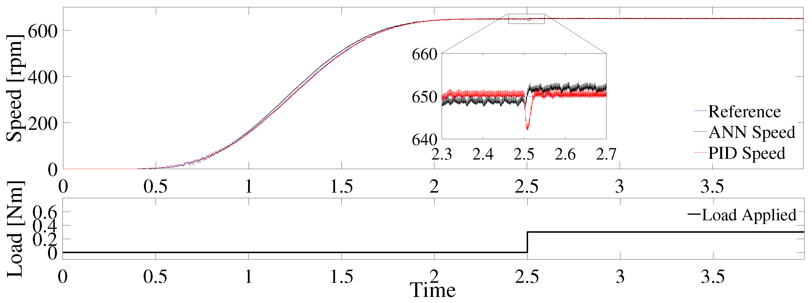
With the finality of extending these results, a test was also performed with a constant load torque applied to the BLDC motor and variable load torques.
Having seen the performance of the systems under conditions known, as are the values close to those of neural network training, it was proceeded to evaluate the system control with values different from these. In this test, the system was subjected to a load torque. The applied load was 0.3 Nm at s.
Under these characteristics, Figure 11 shows the speed monitoring from a speed of 0 rpm to 650 rpm. In this figure, it is possible to emphasize that the neural network is capable of compensating the speed response to this applied load torque. It should be noted that this applied torque was not used for network training.
Although the neural network indeed maintains an error with respect to the reference value, especially after the application of the load, it can be seen that the response of the network is smoother and without transients that could affect the performance of the plant as with the PID response.
Continuing with the analysis of this test, Figure 12 shows the control output of the neural network, which minimizes the speed error. Here, we also observe the comparison of the current consumed by the inverter for both the grid and the PID.
An important point that should be mentioned is that, in this implementation of the control by the neural network, the output speed of the system is not given as feedback. Therefore, this neural network control can be considered as a sensorless type system. The latter is due to it not being necessary to measure the speed for the system to work acceptably, with the inclusion of a system that does not require excessive computational load, and that does not use a sensor to measure speed. This allows us to make the implementation less expensive, mainly in computational terms. Therefore, the use of a neural network for the control of this type of motors is a highly recommended element to carry out the control.
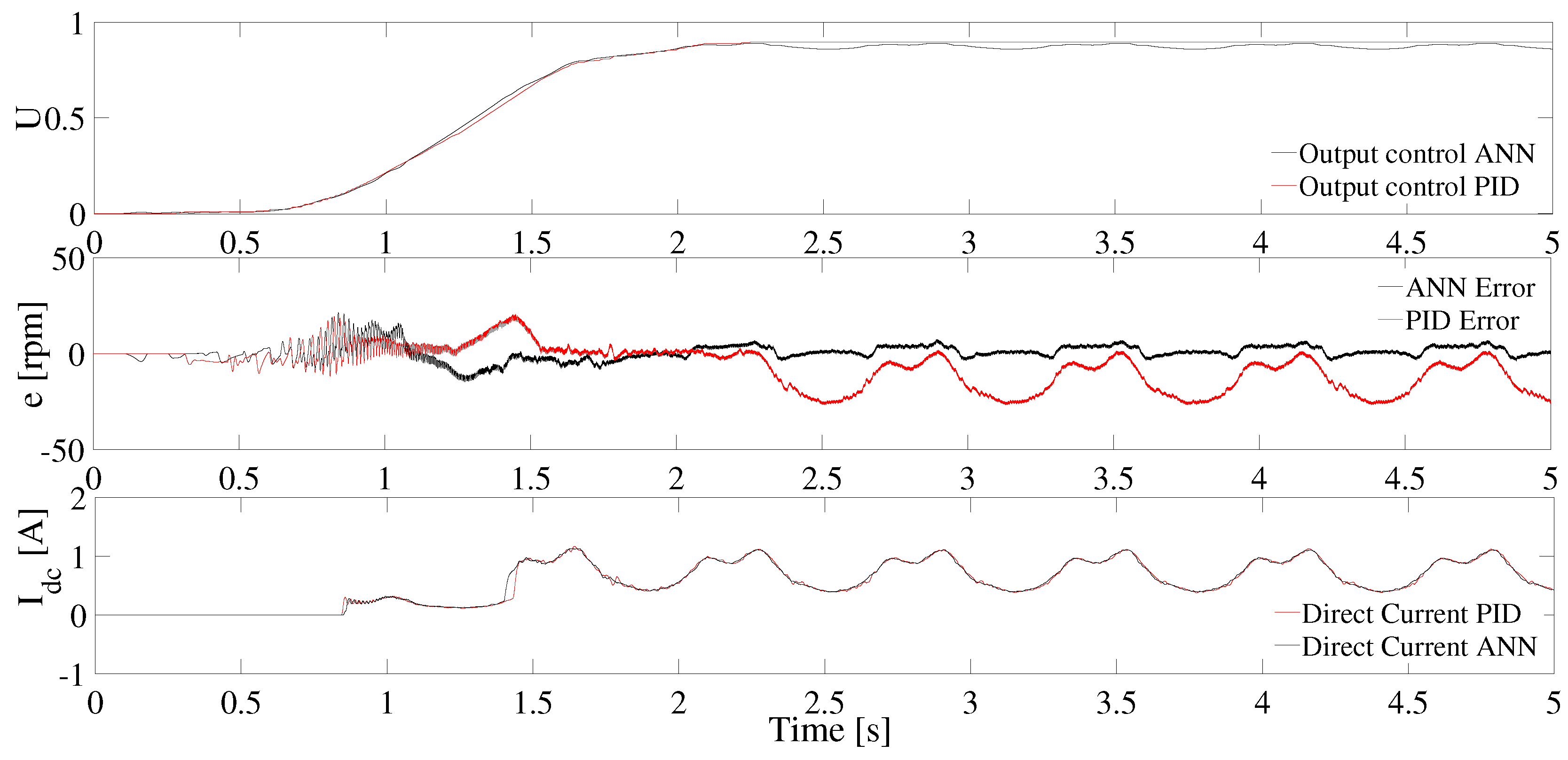
Finally, a test was performed where the system was subjected to the same desired speed path as the previous tests. However, to carry out this test, the system was subjected to a variable load torque. This torque load varied from 0 to 0.7 Nm in an irregular way and can be seen in the lower part of Figure 13.
This experiment gave us an interesting result and is the one presented in Figure 13. In this figure, it is observed that, despite the variable load torque, the system implemented with the neural network is capable of responding to this load variation. However, the PID controller fails to respond to these load variations adequately.
The reason the PID is unable to respond to changes in applied load variation is that the PID control signal becomes saturated and prevents it from reacting adequately to variable torque changes.
Another important point to highlight in this test is that the error generated by the neural network is less and closer to the value of zero than that obtained by the PID. This can be seen in Figure 14.
Controller Performance
Sometimes, it could be challenging to follow the graphics where the results are shown. The graphics are indeed a better way to present information but tiny, and essential details, are possibly not highlighted.
For this reason, in this section, some specific parameters like the controller performance, the power consumption, and the mean square error will be presented to give another point of view of the advantages in the approach presented in this work.
Some notes about the tables are next. The test marked as “No-load applied” belongs to the experiment shown in Figure 9 and Figure 10, while the legend “Constant load applied” is for the results in Figure 11 and Figure 12. The results presented in Figure 13 and Figure 14 are labeled as “Variable load applied.”
Beginning with our explanation, Table 3 shows the performance developed by each controller. Here, it is possible to see the different tests done and the performance obtained in every case. In this Table 3, it is easy to observe that the performance carried out by the two controllers is so close. However, the controller implemented through neural networks is robust since its performance, in the three cases, is around 99%. Meanwhile that made by the PID begins to show a dispersion when the load is applied to the motor varies.
Concerning the mean square error, similar behavior is observed. In this case, Table 4 shows the way that the error grows for the two controllers as the load applied to the BLDC motor varies. From the results presented in Table 4, it is evident that the values shown are high. This is due to the oscillations generated by the controllers when trying to follow the desired speed. Even so, the fact that the controller made by the neural network has a tendency to be more close to the desired value must be highlighted since the mean square error values in all three cases are lower than in the PID controller.
Finally, Table 5 exhibits the values corresponding to the average power consumption for each controller in the different tests carried out. As a reference value, the BDLC motor used for the experiments in this work can deliver a maximal power of 50 Watts. Thus, the values that are shown in Table 5 tell us that the PID controller wears more power than the one made using the neural network. In the test with a no-load applied, the power consumption in both controllers has almost the same value for both PID and Neural network controllers with just a minimal variation of 0.0529 Watts. In the other two tests, the power that is expended by the PID controller begins to grow; meanwhile, the power expended by the neural network maintains stable growth without significant variations. Here, again, the neural network controller is better than the PID controller.
5. Discussion
In order to clarify some points about the results obtained, a discussion will be presented in this section.
One of the considerations that it is necessary to comment on is the fact that, when a BLCD motor does not have Hall sensor, the counter electromotive force detection methods are commonly used to know the position of the motor at all times.
However, when the BLCD is fixed, no counter electromotive force is generated; therefore, there is no information on the position of the stator and rotor. The above mentioned is why motor starting methods are used, such as starting the motor in an open-loop configuration by activating the coils in a predetermined sequence. Now, when using Hall sensors, the use of digital tachometers based on the time of the rising edge of one of the Hall sensors or use of external sensors dedicated to speed reading, such as encoders or resolvers, solves the problem of starting and running the engine at low speeds.
Therefore, this work addresses the use of Hall sensors to control switching by varying the PWM output signals that go to the driver (see Figure 3 and Figure 7).
Another consideration is that the term sensorless refers to the fact that, in this approach, no external sensor or digital tachometers are used; that is, the proposed system only makes use of the desired speed and applied torque.
The next point to take into account is the expected performance of the control implemented using neural networks. It is evident that there will almost always be differences between real models and those used experimentally on simulations.
Independently of the method used to simulate a system like that shown in this work, it is almost certainly necessary to make adjustments in the real implementation. For this reason, the logical step to develop is to retrain the neural network. However, some points must be taken into account. First, the fact of the vectors for training the neural network to develop the proposed control were obtained from the real parameters of the BLDC motor target in this work. The above gives us an idea of the behavior of the real from the simulation tests. The physical parameters and variation due to wear are indeed an essential variable in the real motor. This is going to have a direct impact on the BLDC motor performance. However, the behavior of the real is expected to be closely similar to simulation. From the experience of when other control approaches have been applied, similar results have been obtained both in simulation and in the real system, especially in terms of the speed and current values obtained.
However, the behavior of the real and simulation tests is expected to be very similar since different control approaches have been applied, obtaining similar simulation and real results in terms of speed and current.
Finally, one last question arises: what if the BLDC motor changes? Here, the expected response of the neural network will be close to the training done. This means that the neural network will be able to always control the motor, and the parameters of the BLDC motor are near the value used to train in our work. The above mentioned is due to the ability of the neural networks to generalize information from data learning. It is an advantage of the neural networks facing other methods like PID, since the neural network will only need to be trained if the parameters of the motor to be controlled are very different. While a PID is just one variable changes slightly, the system needs to be tuned again.
6. Conclusions
In this work, an implementation of the speed control of a BLDC motor using a multi-layer perceptron type neural network was presented. From the tests carried out in this article, it was observed that the control implemented from the proposed neural network scheme is efficient, and satisfactory results similar to those presented by a PID in the presence of constant load pairs are obtained.
According to the results obtained in the different tests and experiments carried out in our implementation, it was evident that the neural network is superior to a PID control. This is because, in most real applications, it is difficult to find a constant load torque; therefore, the use of a PID control may not be appropriate for a system. This is highlighted by the fact that the PID control is not capable of supporting variable load changes. At this point, the neural network was superior since it is capable of supporting torque changes without the need for a speed sensor.
Finally, it is noted that the implementation of the neural network is computationally less expensive since it only needs nine neurons distributed in two layers. This will allow the future implementation of this control in embedded hardware.
Among the perspectives considered for the continuation of this work, just two of them will be mentioned—first, to implement this controller in an embedded system to validate its performance in a real system. Secondly, the improvement-oriented towards obtaining a system that does not depend on any sensor in which the neural network functions as the observers required for motor control.
For the above, the problem of starting the BLCD motor must be considered because, as it does not have any sensor, the observers will not give results at speeds close to zero, therefore it implies a greater challenge.
Author Contributions
Investigation, writing—original draft preparation, software, and validation, O.-D.R.-C.; Conceptualization, Project administration, and writing—review and editing, F.T.-R. All authors have read and agreed to the published version of the manuscript.
Funding
This research received no external funding.
Conflicts of Interest
The authors declare no conflict of interest.
References
- Zhao, M.; Liu, X.; Su, H. Robust adaptive speed control of disturbed brushless direct current motor. In Proceedings of the 2017 Eighth International Conference On Intelligent Control and Information Processing (ICICIP), Hangzhou, China, 3–5 November 2017; pp. 141–146. [Google Scholar] [CrossRef]
- Shanmugasundram, R.; Zakaraiah, K.M.; Yadaiah, N. Modeling, simulation and analysis of controllers for brushless direct current motor drives. J. Vib. Control 2013, 19, 1250–1264. [Google Scholar] [CrossRef]
- Arulmozhiyal, R.; Kandiban, R. Design of fuzzy PID controller for brushless DC motor. In Proceedings of the 2012 International Conference on Computer Communication and Informatics, Coimbatore, India, 10–12 January 2012; pp. 1–7. [Google Scholar] [CrossRef]
- Premkumar, K.; Manikandan, B. Adaptive neuro-fuzzy inference system based speed controller for brushless DC motor. Neurocomputing 2014, 138, 260–270. [Google Scholar] [CrossRef]
- Al-Maliki, A.Y.; Iqbal, K. FLC-based PID controller tuning for sensorless speed control of DC motor. In Proceedings of the 2018 IEEE International Conference on Industrial Technology (ICIT), Lyon, France, 20–22 February 2018; pp. 169–174. [Google Scholar] [CrossRef]
- Mamadapur, A.; Mahadev, G.U. Speed Control of BLDC Motor Using Neural Network Controller and PID Controller. In Proceedings of the 2019 2nd International Conference on Power and Embedded Drive Control (ICPEDC), Chennai, India, 21–23 August 2019; pp. 146–151. [Google Scholar] [CrossRef]
- Liu, L.; Liu, Y.J.; Chen, C.P. Adaptive neural network control for a DC motor system with dead-zone. Nonlinear Dyn. 2013, 72, 141–147. [Google Scholar] [CrossRef]
- Ibrahim, H.; Hassan, F.; Shomer, A.O. Optimal PID control of a brushless DC motor using PSO and BF techniques. Ain Shams Eng. J. 2014, 5, 391–398. [Google Scholar] [CrossRef] [Green Version]
- Ramya, A.; Balaji, M.; Kamaraj, V. Adaptive MF tuned fuzzy logic speed controller for BLDC motor drive using ANN and PSO technique. J. Eng. 2019, 2019, 3947–3950. [Google Scholar] [CrossRef]
- Potnuru, D.; Mary, K.A.; Babu, C.S. Experimental implementation of Flower Pollination Algorithm for speed controller of a BLDC motor. Ain Shams Eng. J. 2019. [Google Scholar] [CrossRef]
- Wang, M.S.; Chen, S.C.; Shih, C.H. Speed control of brushless DC motor by adaptive network-based fuzzy inference. Microsyst. Technol. 2018, 24, 33–39. [Google Scholar] [CrossRef]
- Templos-Santos, J.L.; Aguilar-Mejia, O.; Peralta-Sanchez, E.; Sosa-Cortez, R. Parameter Tuning of PI Control for Speed Regulation of a PMSM Using Bio-Inspired Algorithms. Algorithms 2019, 12, 54. [Google Scholar] [CrossRef] [Green Version]
- Merugumalla, M.K.; Kumar, N.P. FFA-based speed control of BLDC motor drive. Int. J. Intell. Eng. Inform. 2018, 6, 325–342. [Google Scholar] [CrossRef]
- ELkholy, M.M.; El-Hay, E.A. Efficient dynamic performance of brushless DC motor using soft computing approaches. Neural Comput. Appl. 2019, 1–14. [Google Scholar] [CrossRef]
- Yu, J.; Shi, P.; Dong, W.; Chen, B.; Lin, C. Neural network-based adaptive dynamic surface control for permanent magnet synchronous motors. IEEE Trans. Neural Netw. Learn. Syst. 2014, 26, 640–645. [Google Scholar] [CrossRef] [PubMed]
- Cheng, J.; Zhang, G.; Lu, C.; Wu, C.; Xu, Y. Research of brushless DC motor control system based on RBF neural network. In Proceedings of the 2017 32nd Youth Academic Annual Conference of Chinese Association of Automation (YAC), Hefei, China, 19–21 May 2017; pp. 521–524. [Google Scholar] [CrossRef]
- Abed, W.; Sharma, S.; Sutton, R. Diagnosis of bearing fault of brushless DC motor based on dynamic neural network and orthogonal fuzzy neighborhood discriminant analysis. In Proceedings of the 2014 UKACC International Conference on Control (CONTROL), Loughborough, UK, 9–11 July 2014; pp. 378–383. [Google Scholar] [CrossRef]
- Luo, S.; Wu, S.; Gao, R. Chaos control of the brushless direct current motor using adaptive dynamic surface control based on neural network with the minimum weights. Chaos Interdiscip. J. Nonlinear Sci. 2015, 25, 073102. [Google Scholar] [CrossRef] [PubMed]
- Saleh, A.L.; Obed, A.A.; Qasim, H.H.; Breesam, W.I.; Al-Yasir, Y.I.; Parchin, N.O.; Abd-Alhameed, R.A. Wavelet Neural Networks for Speed Control of BLDC Motor. In Energy Dissipation; IntechOpen: London, UK, 2020. [Google Scholar] [CrossRef] [Green Version]
- Naung, Y.; Anatolii, S.; Lin, Y.H. Speed Control of DC Motor by Using Neural Network Parameter Tuner for PI-controller. In Proceedings of the 2019 IEEE Conference of Russian Young Researchers in Electrical and Electronic Engineering (EIConRus), Saint Petersburg/Moscow, Russia, 28–31 January 2019; pp. 2152–2156. [Google Scholar] [CrossRef]
- Kim, C.H. Artificial Intelligent Control for DC Motor via Dynamic Neural Networks. J. Korean Soc. Railw. 2019, 22, 467–472. [Google Scholar] [CrossRef]
- Ho, T.Y.; Chen, Y.J.; Chen, P.H.; Hu, P.C. The design of a motor drive based on neural network. In Proceedings of the 2017 International Conference on Applied System Innovation (ICASI), Sapporo, Japan, 13–17 May 2017; pp. 337–340. [Google Scholar] [CrossRef]
- Khadar, S.; Kouzou, A.; Rezzaoui, M.M.; Hafaifa, A. Sensorless control technique of open-end winding five phase induction motor under partial stator winding short-circuit. Period. Polytech. Electr. Eng. Comput. Sci. 2020, 64, 2–19. [Google Scholar] [CrossRef] [Green Version]
- König, N.; Nienhaus, M.; Grasso, E. Analysis of Current Ripples in Electromagnetic Actuators with Application to Inductance Estimation Techniques for Sensorless Monitoring. Actuators 2020, 9, 17. [Google Scholar] [CrossRef] [Green Version]
- Che, H.; Wu, B.; Yang, J.; Tian, Y. Speed sensorless sliding mode control of induction motor based on genetic algorithm optimization. Meas. Control 2020, 53, 192–204. [Google Scholar] [CrossRef] [Green Version]
- Wu, S.; Zhang, J. A terminal sliding mode observer based robust backstepping sensorless speed control for interior permanent magnet synchronous motor. Int. J. Control Autom. Syst. 2018, 16, 2743–2753. [Google Scholar] [CrossRef]
- Aguilar, L.; Ramírez-Villalobos, R.; Ferreira de Loza, A.; Coria, L. Robust sensorless speed tracking controller for surface-mount permanent magnet synchronous motors subjected to uncertain load variations. Int. J. Syst. Sci. 2020, 51, 35–48. [Google Scholar] [CrossRef]
- Kivanc, O.C.; Ozturk, S.B. Low-Cost Position Sensorless Speed Control of PMSM Drive Using Four-Switch Inverter. Energies 2019, 12, 741. [Google Scholar] [CrossRef] [Green Version]
- Urbanski, K.; Janiszewski, D. Sensorless Control of the Permanent Magnet Synchronous Motor. Sensors 2019, 19, 3546. [Google Scholar] [CrossRef] [Green Version]
- Wang, B.; Wang, Y.; Feng, L.; Jiang, S.; Wang, Q.; Hu, J. Permanent-Magnet Synchronous Motor Sensorless Control Using Proportional-Integral Linear Observer with Virtual Variables: A Comparative Study with a Sliding Mode Observer. Energies 2019, 12, 877. [Google Scholar] [CrossRef] [Green Version]
- Shiva, B.S.; Verma, V.; Khan, Y.A. Q-MRAS-based speed sensorless permanent magnet synchronous motor drive with adaptive neural network for performance enhancement at low speeds. In Innovations in Soft Computing and Information Technology; Springer: Singapore, 2019; pp. 103–116. [Google Scholar] [CrossRef]
- Elbeji, O.; Hannachi, M.; Benhamed, M.; Sbita, L. Artificial neural network-based sensorless control of wind energy conversion system driving a permanent magnet synchronous generator. Wind Eng. 2020, 0309524X20903252. [Google Scholar] [CrossRef]
- Sreeram, K. Design of fuzzy logic controller for speed control of sensorless BLDC motor drive. In Proceedings of the 2018 International Conference on Control, Power, Communication and Computing Technologies (ICCPCCT), Kannur, India, 23–24 March 2018; pp. 18–24. [Google Scholar] [CrossRef]
- Saed, N.; Mirsalim, M. Enhanced sensor-less speed control approach based on mechanical offset for dual-stator brushless DC motor drives. IET Electr. Power Appl. 2020, 14, 885–892. [Google Scholar] [CrossRef]
- Vanchinathan, K.; Valluvan, K. A metaheuristic optimization approach for tuning of fractional-order PID controller for speed control of sensorless BLDC motor. J. Circuits Syst. Comput. 2018, 27, 1850123. [Google Scholar] [CrossRef]
- Verma, V.; Pal, N.S.; Kumar, B. Speed Control of the Sensorless BLDC Motor Drive Through Different Controllers. In Harmony Search and Nature Inspired Optimization Algorithms; Springer: Singapore, 2019; pp. 143–152. [Google Scholar] [CrossRef]
- Rif’an, M.; Yusivar, F.; Kusumoputro, B. Sensorless-BLDC motor speed control with ensemble Kalman filter and neural network. J. Mechatron. Electr. Power Veh. Technol. 2019, 10, 1–6. [Google Scholar] [CrossRef] [Green Version]
- Veras, F.C.; Lima, T.L.V.; Souza, J.S.; Ramos, J.G.G.S.; Lima Filho, A.C.; Brito, A.V. Eccentricity Failure Detection of Brushless DC Motors From Sound Signals Based on Density of Maxima. IEEE Access 2019, 7, 150318–150326. [Google Scholar] [CrossRef]
- Medeiros, R.L.V.; Filho, A.C.L.; Ramos, J.G.G.S.; Nascimento, T.P.; Brito, A.V. A Novel Approach for Speed and Failure Detection in Brushless DC Motors Based on Chaos. IEEE Trans. Ind. Electron. 2019, 66, 8751–8759. [Google Scholar] [CrossRef]
- Garcia-Calva, T.A.; Morinigo-Sotelo, D.; Garcia-Perez, A.; Camarena-Martinez, D.; de Jesus Romero-Troncoso, R. Demodulation Technique for Broken Rotor Bar Detection in Inverter-Fed Induction Motor Under Non-Stationary Conditions. IEEE Trans. Energy Convers. 2019, 34, 1496–1503. [Google Scholar] [CrossRef]
- Delgado-Arredondo, P.A.; Morinigo-Sotelo, D.; Osornio-Rios, R.A.; Avina-Cervantes, J.G.; Rostro-Gonzalez, H.; de Jesus Romero-Troncoso, R. Methodology for fault detection in induction motors via sound and vibration signals. Mech. Syst. Signal Process. 2017, 83, 568–589. [Google Scholar] [CrossRef]
- Zamudio-Ramirez, I.; Osornio-Rios, R.A.; Trejo-Hernandez, M.; Romero-Troncoso, R.d.J.; Antonino-Daviu, J.A. Smart-Sensors to Estimate Insulation Health in Induction Motors via Analysis of Stray Flux. Energies 2019, 12, 1658. [Google Scholar] [CrossRef] [Green Version]
- Zhou, Z.; Li, S.; Zhou, Y.; Jiao, Y. Simulation of BLDC in Speed Control System on PSIM and Matlab/Simulink Co-simulation Platform. In Proceedings of the First, Symposium on Aviation Maintenance and Management, Xi’an, China, 25–28 November 2013; pp. 621–629. [Google Scholar] [CrossRef]
- Mozaffari Niapour, S.; Shokri Garjan, G.; Shafiei, M.; Feyzi, M.; Danyali, S.; Bahrami Kouhshahi, M. Review of permanent-magnet brushless DC motor basic drives based on analysis and simulation study. Int. Rev. Electr. Eng. 2014, 9, 930–957. [Google Scholar] [CrossRef] [Green Version]
- Frolov, V.Y.; Zhiligotov, R.I. Development of sensorless vector control system for permanent magnet synchronous motor in Matlab Simulink. J. Min. Inst. 2018, 229. [Google Scholar] [CrossRef]
- Nautiyal, C.T.; Singh, S.; Rana, U. Recognition of noisy numbers using neural network. In Soft Computing: Theories and Applications; Springer: Singapore, 2018; pp. 123–132. [Google Scholar] [CrossRef]
- Ramirez-Leyva, F.; Trujillo-Romero, F.; Caballero-Morales, S.; Peralta-Sanchez, E. Direct Torque Control of a Permanent-Magnet Synchronous Motor with Neural Networks. In Proceedings of the 2014 International Conference on Electronics, Communications and Computers (CONIELECOMP), Cholula, Mexico, 26–28 February 2014; pp. 71–76. [Google Scholar] [CrossRef]
- Trujillo-Romero, F.; Jimenez Hernandez, J.d.C.; Gomez Lopez, W. Predicting electricity consumption using neural networks. IEEE Lat. Am. Trans. 2011, 9, 1066–1072. [Google Scholar] [CrossRef]
- Badillo, H.Y.; Olvera, R.T.; Mejía, O.A.; Carbajal, F.B. Control Neuronal en Línea para Regulación y Seguimiento de Trayectorias de Posición para un Quadrotor. Revista Iberoamericana de Automática e Informática industrial 2017, 14, 141–151. [Google Scholar] [CrossRef] [Green Version]
- Wu, S.; Liu, J. Simulation Analysis of Dynamic Characteristics of AC Motor Based on BP Neural Network Algorithm. In Proceedings of the International Conference on Cyber Security Intelligence and Analytics, Shenyang, China, 21–22 February 2019; pp. 277–286. [Google Scholar] [CrossRef]
- Sadrossadat, S.A.; Rahmani, O. ANN-based method for parametric modelling and optimising efficiency, output power and material cost of BLDC motor. IET Electr. Power Appl. 2020, 14, 951–960. [Google Scholar] [CrossRef]
- Mishra, P.; Banerjee, A.; Ghosh, M. FPGA Based Real-Time Implementation of Quadral-Duty Digital PWM Controlled Permanent Magnet BLDC Drive. IEEE ASME Trans. Mechatron. 2020. [Google Scholar] [CrossRef]
Figure 1.
Waveforms of the counter-electric force in 120 electrical degrees.

Figure 2.
Inverter-BLDC system implemented in PSIM.

Figure 3.
Block diagram of the PID control used.

Figure 4.
Training signal without torque load applied.

Figure 5.
Values obtained from the PID controller .

Figure 6.
Training values obtained from PID control with different loads applied.

Figure 7.
Configuration diagram for the BLDC system.

Figure 8.
Implementation of the Matlab/Simulink-PSIM simulation system.

Figure 9.
Speed response of the neural network and the PID with no load applied to the plant.

Figure 10.
Control signals, speed, and current error on the controller CD bus with the neural network and with the PID.
Figure 10.
Control signals, speed, and current error on the controller CD bus with the neural network and with the PID.

Figure 11.
Speed response of the neural network and the PID to two applied load changes.

Figure 12.
Control signals, speed, and current error on the CD bus for the neural network and the PID.
Figure 12.
Control signals, speed, and current error on the CD bus for the neural network and the PID.

Figure 13.
Speed response of the neural network and the PID by applying a variable load over time.

Figure 14.
Speed response of the neural network and the PID by applying a variable load over time.


Table 1.
Neural network parameters.
| Parameter | Value |
|---|---|
| Number of layers | 2 |
| Input layer neurons | 8 |
| Activation function | Sigmoidal |
| Output layer neurons | 1 |
| Activation function | Lineal |
| ANN architecture | Multi-layer perceptron |
| Training algorithm | Backpropgation |
| Variant | Levenberg–Marquardt |
| Performance | Mean Squared Error |
| Epoch | 5000 |
Table 2.
Motor parameters.
| Parameter | Value |
|---|---|
| Stator resistance () | 0.15 |
| Stator self-inductance () | H |
| Stator mutual induction | H |
| Vpk/krpm | 78.9 V |
| Vrms/krpm | 55.86 V |
| Number of poles (P) | 30 |
| Moment of inertia (J) | kgm |
| Mechanical time constant | 0.2369 |
Table 3.
Controller performance.
| LOAD | PID | ANN |
|---|---|---|
| No-load applied | 0.1186% | 0.0332 % |
| Constant load applied | 0.1351 % | 0.0930 % |
| Variable load applied | 2.9911 % | 0.3147 % |
Table 4.
Mean square error for the controller implemented.
| LOAD | PID | ANN |
|---|---|---|
| No-load applied | 952.18 | 425.4980 |
| Constant load applied | 1132.7 | 514.3944 |
| Variable load applied | 2794.2 | 946.8229 |
Table 5.
Average power consumption.
| LOAD | PID | ANN |
|---|---|---|
| No-load applied | 14.4753 W | 14.4224 W |
| Constant load applied | 27.127 W | 21.72 W |
| Variable load applied | 32.2768 W | 25.8408 W |
© 2020 by the authors. Licensee MDPI, Basel, Switzerland. This article is an open access article distributed under the terms and conditions of the Creative Commons Attribution (CC BY) license (http://creativecommons.org/licenses/by/4.0/).
Share and Cite
MDPI and ACS Style
Ramírez-Cárdenas, O.-D.; Trujillo-Romero, F. Sensorless Speed Tracking of a Brushless DC Motor Using a Neural Network. Math. Comput. Appl. 2020, 25, 57. https://0-doi-org.brum.beds.ac.uk/10.3390/mca25030057
AMA Style
Ramírez-Cárdenas O-D, Trujillo-Romero F. Sensorless Speed Tracking of a Brushless DC Motor Using a Neural Network. Mathematical and Computational Applications. 2020; 25(3):57. https://0-doi-org.brum.beds.ac.uk/10.3390/mca25030057
Chicago/Turabian StyleRamírez-Cárdenas, Oscar-David, and Felipe Trujillo-Romero. 2020. "Sensorless Speed Tracking of a Brushless DC Motor Using a Neural Network" Mathematical and Computational Applications 25, no. 3: 57. https://0-doi-org.brum.beds.ac.uk/10.3390/mca25030057