Article

Statistical Characteristics of a Twisted Anisotropic Gaussian Schell-Model Beam in Turbulent Ocean

1
Shandong Provincial Engineering and Technical Center of Light Manipulations & Shandong Provincial Key Laboratory of Optics and Photonic Device, School of Physics and Electronics, Shandong Normal University, Jinan 250358, China
2
Collaborative Innovation Center of Light Manipulations and Applications, Shandong Normal University, Jinan 250358, China
3
School of Physical Science and Technology, Soochow University, Suzhou 215006, China
*
Author to whom correspondence should be addressed.
Submission received: 11 May 2020 / Revised: 25 May 2020 / Accepted: 28 May 2020 / Published: 29 May 2020
(This article belongs to the Special Issue Recent Advances in the Study of Light Propagation in Optical Fibers)

Abstract

:
The analytical expression of the cross-spectral density function of a twisted anisotropic Gaussian Schell-model (TAGSM) beam transmitting in turbulent ocean is derived by applying a tensor method. The statistical properties, including spectral density, the strength of twist and beam width of the propagating beam are studied carefully through numerical examples. It is demonstrated that the turbulence of ocean has no effect on the rotation direction of the beam spot during propagation. However, the beam shape will degrade into a Gaussian profile under the action of oceanic turbulence with sufficiently long propagation distance, and a beam with a larger initial twist factor is more resistant to turbulence-induced degeneration. As oceanic turbulence becomes stronger, the beam spot spreads more quickly while the twist factor drops more rapidly upon propagation. The physical mechanisms of these phenomena are addressed in detail. The obtained results will be helpful in optical communication systems underwater.

Graphical Abstract

1. Introduction

In 1993, a twist phase was first imparted to a Gaussian Schell-model (GSM) beam, the most classical type of partially coherent beam [1]. It has the form exp[iμk(x1y2-x2y1)], where k is the magnitude of the wave vector and μ is the twist factor (a measure of the strength of the twist phase); (x1, y1) and (x2, y2) are two points in the transverse plane, perpendicular to the propagation axis of the light beam. Notably different from the conventional quadratic phase or vortex phase, the twist phase is an intrinsic two-dimensional phase and related with two points. In addition, the twist factor is bounded in strength |μ| ≤ 1/(02), with δ0 being the transverse coherence width, to ensure a bona fide twisted beam, and, therefore, the twist phase vanishes in the coherent limit (i.e., δ0 tends to infinity). This unique phase endows partially coherent beam with a new degree of freedom and brings about some interesting and useful properties. The beam impressed with twist phase possesses orbital angular momentum (OAM), and its beam spot rotates during propagation due to the twist phase [1,2]. The statistical characteristics of a TGSM beam propagating through a paraxial ABCD optical system [3,4], diffractive axicons [5,6], dispersive and absorptive media [7], uniaxial crystals [8] and random media [9,10] have been extensively studied. It have been confirmed that the twist phase can play an important role in optical imaging, optical trapping and optical communications. The TGSM beam can be used an illumination to overcome the classical Rayleigh limit by an order in imaging systems [11]. The twist phase can be used to enlarge the trapping area when a partially coherent beam is applied for trapping Rayleigh particles [12], and it also has the ability to reduce the turbulence-induced scintillation of the beam during its passing through a turbulent atmosphere [13]. Recently, a bona-fide TGSM beam has been generated by Wang et al., which makes progress toward its application [14].
As the twist phase imposed on a partially coherent beam has the possibility of destroying the nonnegativity of the beam’s cross-spectral density (CSD) function, it cannot be imposed on a partially coherent beam arbitrarily. As a result, the aforementioned studies were confined to the TGSM beam, which is the most-used and simplest class of twisted partially coherent beam. Recently, Borghi and co-workers proposed a modal analysis method to decide whether a twist phase can be imposed on a partially coherent beam with axial symmetry [15]. Later, the sufficient and necessary conditions for devising a genuine twisted CSD function with axial symmetry were obtained by Borghi [16]. Mei and Korotkova proposed another method for devising the bona-fide twisted CSD function [17]. More recently, Gori et al. presented a general mathematical formula for devising the genuine twisted CSD function with axial or rectangular symmetry [18]. Owing to these works, the twist phase has renewed the interest of researchers. Different kinds of theoretical models for twisted CSD functions were proposed, and the propagations of these new twisted beams passing through free space, uniaxial crystals and linearly random media were explored in detail [19,20,21,22,23,24,25,26].
In order to realize the further utilization of laser beams in the fields of remote sensing and imaging and wireless information transmission [27,28,29,30,31,32], it is urgent to investigate the propagation characteristics of laser beams in random media such as turbulent atmosphere and ocean [33,34,35]. Nevertheless, in the case of atmospheric or oceanic transmission, the beam will experience extra beam spreading, beam wander, intensity fluctuation and coherence degradation, which greatly limit the performance of the optical systems. The turbulence of ocean is somewhat more complicated than that of atmosphere. It can be characterized by the random index-of-refraction fluctuation of optical waves [36,37,38], which is dependent on the relative strength of temperature salinity fluctuations ( ω ), the rate of dissipation of mean-square temperature ( χ T ) and turbulent kinetic energy per unit mass of fluid ( ε ). In general, oceanic turbulence is much stronger than atmospheric turbulence under the same traveling distance.
Owing to their important applications in underwater communications and imaging, the transmission characteristics of a variety of laser beams such as vector beams [39,40,41,42], high-order beams/beam arrays [43,44,45] and partially coherent beams [46,47,48] travelling through turbulent ocean have been revealed.
It has been confirmed that one could reduce the turbulence-induced degradation effects to some extent by modulating the state of polarization, transverse coherence width and beam mode of the incident laser beam [49,50,51]. As we stated previously, the twist phase gives a new degree of freedom to a partially coherent beam. Some studies have shown that twisted beams can abate/overcome the degradation effects induced by turbulent atmosphere [14,52,53]. However, the behavior of twisted beams in turbulent ocean has not been well analyzed so far.
In this paper, the twist phase is embedded to an anisotropic Gaussian Schell-model (AGSM) beam, and we name it a twisted anisotropic Gaussian Schell-model (TAGSM) beam. We will explore the propagation characteristics of the beam under the action of oceanic turbulence. In Section 2, the precise expression for the CSD of a TAGSM beam passing through turbulent ocean is obtained with the aid of a tensor method. In Section 3, the effect of oceanic turbulence on second-order statistics characteristics such as intensity distribution, beam width and transverse coherence width is analyzed in detail through numerical simulation, and we present a summarization in Section 4.

2. The CSD Function of a TAGSM Beam Passing through in Turbulent Ocean

As a statistically stationary, monochromatic, random beam-like field, a partially coherent beam can be described by a two-point correlated CSD function within the space-frequency domain as W 0 ( r 1 , r 2 ) = E ( r 1 ) E ( r 2 ) , where r 1 = ( x 1 , y 1 ) T and r 2 = ( x 2 , y 2 ) T are two position vectors in the transverse plane perpendicular to the propagating direction, E represents the random electric field, the superscript “T” stands for vector transposition, and the asterisk and angular brackets denote the complex conjugate and averaging over the random fluctuations of the field, respectively. The Gaussian-Schell model (GSM) beam source, which is a classical form of partially coherent beam, can be described by the CSD expression as follows [54]:
W 0 ( r 1 , r 2 ) = [ I 0 ( r 1 ) I 0 ( r 2 ) ] 1 2 g ( r 1 r 2 )
where I ( r ) is optical intensity and g is the spatial complex coherence, which only depends on the difference of r 1 r 2 . Both I and g are of Gaussian distribution. To generalize the notion of Gaussian Schell-model sources to include anisotropies in the source-plane intensity and coherence distributions, an anisotropic Gaussian-Schell model (AGSM) beam is introduced. The CSD of the AGSM beam takes the form [55]:
W 0 ( r 1 , r 2 ) = G 0 exp [ 1 4 r 1 T ( σ I 2 ) 1 r 1 1 4 r 2 T ( σ I 2 ) 1 r 2 1 2 ( r 1 r 2 ) T ( σ g 2 ) 1 ( r 1 r 2 ) ] .
Considering the twist phase is embedded to an AGSM beam, the CSD function of a twisted AGSM beam (TAGSM) as a planar partial coherent source locating at the plane z = 0 and travelling along the z-axis into half-pace z > 0 can be written as [3,4]:
W 0 ( r 1 , r 2 ) = G 0 exp [ 1 4 r 1 T ( σ I 2 ) 1 r 1 1 4 r 2 T ( σ I 2 ) 1 r 2 1 2 ( r 1 r 2 ) T ( σ g 2 ) 1 ( r 1 r 2 ) ] × exp [ i k 2 ( r 1 r 2 ) T ( μ J + R 1 ) ( r 1 + r 2 ) ] ,
where G0 is a normalization constant; σ I 2 and σ g 2 are matrixes of the transverse beam spot width and transverse coherence width, respectively; R 1 is a matrix of wave-front curvature and J is an anti-symmetric matrix. The superscript “−1” in Equation (3) denotes the inverse of the matrix. ( σ I 2 ) 1 , ( σ g 2 ) 1 , R 1 and J are all transpose symmetric matrices of 2 × 2 , expressed as:
( σ I 2 ) 1 = ( 1 / σ I x x 2 1 / σ I x y 2 1 / σ I y x 2 1 / σ I y y 2 ) , ( σ g 2 ) 1 = ( 1 / σ g x x 2 1 / σ g x y 2 1 / σ g y x 2 1 / σ g y y 2 ) ,
R 1 = ( 1 / R x x 1 / R x y 1 / R y x 1 / R y y ) , J = ( 0 1 1 0 ) ,
k is the wavenumber, which is equal to 2 π / λ , with λ being the wavelength; the twist factor μ represents the strength of twist phase. To satisfy the nonnegative definition of the CSD, the value of the twist factor falls inside the range | μ | [ k 2 det ( σ g 2 ) ] 1 / 2 , where det is the determinant of the corresponding matrix. Equation (3) can represent all the known families of fundamental Gaussian beam, Gaussian Schell-model (GSM) beam and TGSM beam. When R 1 = ( σ g 2 ) 1 = 0 and μ = 0 , Equation (3) degrades into the equation for the collimated circular or elliptical Gaussian beam with the matrix ( σ I 2 ) 1 determining the initial shape of the beam. If μ = 0 , and the principal x and y axes of all three matrices R 1 , ( σ g 2 ) 1 and ( σ I 2 ) 1 coincide with the x and y axis of the Cartesian coordinate system established in the laboratory, the beam becomes an aligned astigmatic GSM beam. In most generated cases, if μ 0 and the principal axes of all three matrices do not coincide, the beam turns into a general TAGSM beam. To obtain the CSD formula of a TAGSM beam travelling through turbulent ocean, we rewrite Equation (3) in a more compact tensor form [8], given by:
W ( r ˜ ) = G 0 exp [ i k 2 r ˜ T ( M i 1 ) r ˜ ] ,
where r ˜ T = ( r 1 , r 2 ) = ( x 1 , y 1 , x 2 , y 2 ) is a row matrix. M i 1 represents a partially coherent complex curvature tensor of a 4 × 4 matrix.
M i 1 = ( R 1 + 1 2 i k ( σ I 2 ) 1 + 1 i k ( σ g 2 ) 1 μ J 1 i k ( σ g 2 ) 1 μ J T 1 i k ( σ g 2 ) 1 + 1 2 i k ( σ I 2 ) 1 + 1 i k ( σ g 2 ) 1 R 1 ) ,
When a partially coherent beam passes through turbulent ocean from the source plane to the output plane, within the valid area of paraxial propagating, the CSD of a partially coherent beam passing through turbulent ocean in the output plane can be treated with the help of the extended Huygens–Fresnel (eHF) integral [53]:
W 0 ( ρ ˜ , z ) = k 2 4 π 2 z 2 d 2 r 1 d 2 r 2 W 0 ( r ˜ ) h ( r 1 , ρ 1 ) h ( r 2 , ρ 2 )   × exp [ Ψ ( r 1 , ρ 1 , z ) + Ψ ( r 2 , ρ 2 , z ) ] m ,
where ρ 1 = ( u 1 , v 1 ) T and ρ 2 = ( u 2 , v 2 ) T are two position vectors in the output plane distance z from the source plane. h ( r , ρ ) is the response function in free-space propagation without turbulence:
h ( r , ρ ) = exp ( i k 2 z | r ρ | 2 ) ,
The last term in Equation (8) stands for the contribution of the complicated phase perturbation caused by seawater. The second-order statistics of its ensemble average expressed by angular brackets with subscript “m” will be calculated. Ψ ( r , ρ , z ) signifies the complicated phase for a spherical wave transmitting from ( r , 0 ) to ( ρ , z ) in oceanic turbulence. Supposing that the oceanic turbulence is homogeneous and isotropic, it can be specified by [38,39,40,42]:
exp [ Ψ ( r 1 , ρ 1 , z ) + Ψ ( r 2 , ρ 2 , z ) ] = exp { k 2 z M [ ( r 1 r 2 ) 2 + ( ρ 1 ρ 2 ) 2 + ( ρ 1 ρ 2 ) · ( r 1 r 2 ) ] } ,
with
M = π 2 3 0 + κ 3 Φ n ( κ ) d κ ,
Here, Φ n is the power spectrum of the refractive index fluctuations of the oceanic turbulence, taking the following form:
Φ n ( κ ) = 0.388 × 10 8 ε 1 / 3 κ 11 / 3 [ 1 + 2.35 ( κ η ) 2 / 3 ] f ( κ , ω , χ T ) ,
where κ denotes the spatial frequency of the three dimensions, and ε is the turbulent kinetic energy dissipation rate, where its value varies from 10−10 to 10−4 m2/s3 per unit mass of fluid. η represents the magnitude of the Kolmogorov inner scale with the value of 10−3 m, and
f ( κ , ω , χ T ) = χ T ω ( ω 2 e A T δ + e A s δ 2 ω e A T S δ ) .
χ T in Equation (13) denotes the mean-square temperature dissipation rate, A T , A S and A T S have numerical values of 1.863 × 10 2 ,   1.9 × 10 4 and 9.41 × 10 3 , respectively, and the value of δ depends on the equation δ = 8.284 ( κ η ) 4 / 3 + 12.978 ( κ η ) 2 . Further, ω is the magnitude determined by the temperature and salinity fluctuations of ocean water, and its value varies from −5 to 0, with the dominant cause of optical turbulence changing from the temperature to salinity.
In order to evaluate the eHF integral shown in Equation (8), we first rewrite the response function as the following tensor form:
h ( r 1 , ρ 1 ) h ( r 2 , ρ 2 ) = exp [ i k 2 ( r ˜ T B ˜ 1 r ˜ 2 r ˜ T B ˜ 1 ρ ˜ + ρ ˜ T B ˜ 1 ρ ˜ ) ] ,
with
B ˜ = ( z I 0 0 z I ) ,
I entering in Equation (15) is one 2 × 2 identity matrix and ρ ˜ = ( ρ 1 , ρ 2 ) = ( u 1 , v 1 , u 2 , v 2 ) T . Then, the second-order statistics of Equation (10) can be specific in the tensor form:
exp [ Ψ ( r 1 , ρ 1 , z ) + Ψ ( r 2 , ρ 2 , z ) ] = exp [ i k 2 ( r ˜ T S ˜ r ˜ + r ˜ T S ˜ ρ ˜ + ρ ˜ T S ˜ ρ ˜ ) ] ,
where
S ˜ = 2 k i z T ( I I I I ) ,
On substituting Equations (14) and (16) into Equation (8), and after vector integrating, the CSD function of TAGSM beam in the output plane takes the form:
W o ( ρ ˜ , z ) = [ det ( B ˜ M i 1 + B ˜ S ˜ + I ˜ ) ] 1 / 2 exp ( i k 2 ρ ˜ T M o 1 ρ ˜ ) ,
where the partially coherent curvature tensor M o 1 in the output plane is given by:
M o 1 = ( B ˜ 1 + S ˜ ) ( B ˜ 1 S ˜ 2 ) ( M i 1 + B ˜ 1 + S ˜ ) 1 ( B ˜ 1 S ˜ 2 ) ,
Equation (18) is derived through the integral formula as follows:
d n x exp ( x T A x + i k T x ) = π n / 2 ( det A ) 1 / 2 exp ( 1 4 k T A 1 k ) ,
where x and k are n-dimensional vectors.
By setting ρ 1 = ρ 2 , the spectral density of the TAGSM can be obtained by Equation (18):
S ( ρ ˜ , z ) = [ det ( B ˜ M i 1 + B ˜ S ˜ + I ˜ ) ] 1 / 2 exp [ k 2 i ρ ˜ T M o 1 1 ρ ˜ ] ,
in which ρ ˜ = ( ρ 1 T , ρ 1 T ) = ( u 1 , v 1 , u 1 , v 1 ) T , with M o 1 1 can be simplified as:
M o 1 1 = [ ( M i 1 + S ˜ ) 1 + B ˜ ] 1 ,
In the following section, we will mainly analyze the propagation characteristics of a TAGSM beam passing through turbulent ocean according to Equations (18) and (21).

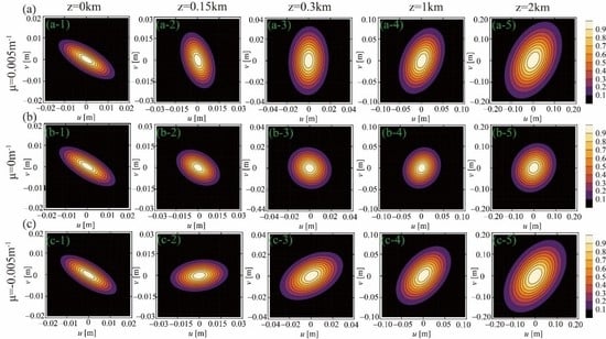
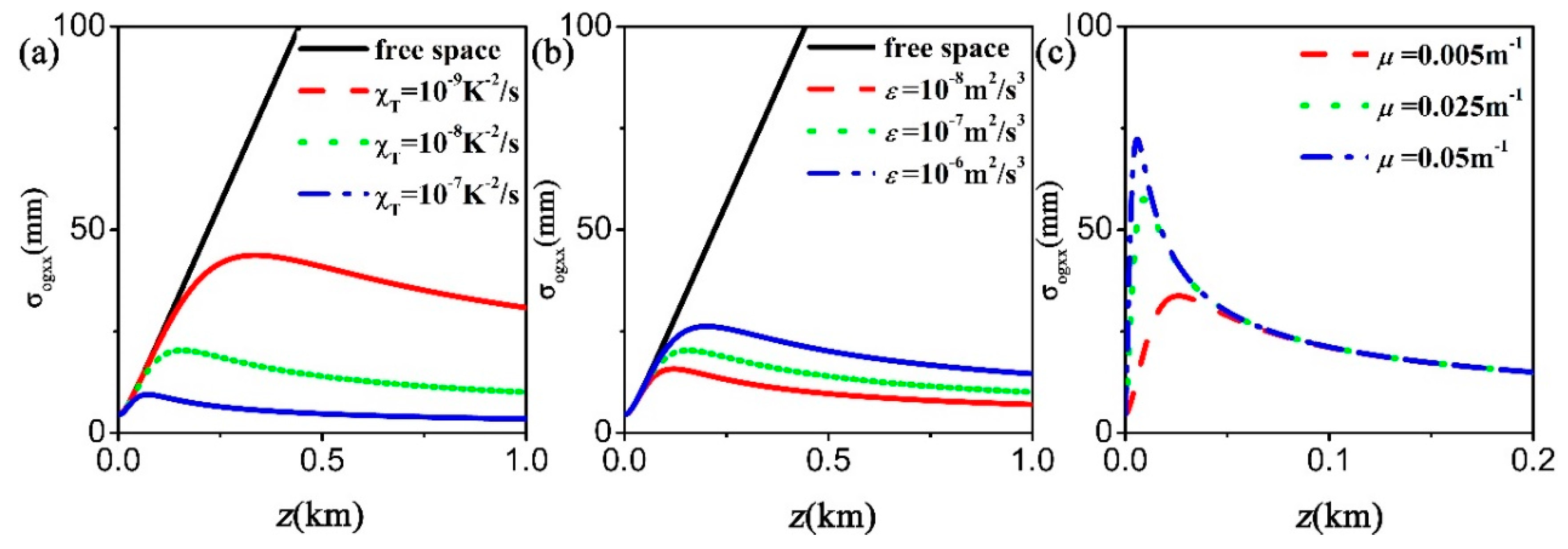
3. Numerical Simulation and Discussion

In this section, the evolution properties of the TAGSM beam propagating turbulent ocean under different beam parameters and turbulence parameters will be discussed with the help of the formulas obtained in the preceding section.
We will first focus on the evolution properties of the intensity distribution on propagation in the absence of oceanic turbulence. Figure 1 shows the contour of the TAGSM beam’s normalized spectral density at different distances. For comparison, the twist factors in Figure 1 are set as 0.005 m−1, 0 and −0.005 m−1 from the first row to the third row, respectively. The other parameters used in the calculation are λ = 632.8   nm ,   R 1 = 0 , ( σ I 2 ) 1 = ( 0.05 0.05 0.05 0.1 )   m m 2 and ( σ g 2 ) 1 = ( 0.05 0 0 0.05 )   m m 2 . One finds from the initial parameters that it is a collimated beam source with an elliptical beam profile (see Figure 1(a-1,b-1,c-1)) and a circular symmetric degree of coherence. The oriental angle θ ( z ) which is formed by the long axis of the elliptical beam spot and x-axis can be extracted from the matrix ( σ I 2 ) 1 at propagation distance z using the following formula:
θ = 90 π arctan ( 2 σ I x x 2 σ I y y 2 σ I x y 2 ( σ I y y 2 σ I x x 2 ) ) .
In the original plane, the value of θ ( z = 0 ) is −31.7 degrees, only depending on the initial parameter ( σ I 2 ) 1 . When the TAGSM beam passes from the original plane to the plane at distance z, besides beam spreading, the beam spot displays clockwise (see Figure 1(a-1–a-5)) or anti-clockwise (see Figure 1(c-1–c-5)) rotation relative to the z-axis due to the effects of the twist phase. At z = 2 km, it approaches π / 2 rotation compared to the angle θ ( z ) in the original plane. For μ = 0, the beam profile does not rotate during propagation, but the angle θ ( z ) will shift from −31.7 degrees to 31.7 degrees at distance z = 0.4 km. This is because the beam spreads much faster along the minor axis than along the major axis, and, therefore, the minor axis will turn to “the major axis” at z = 0.4 km.
In the presence of oceanic turbulence, the propagation properties are very different than those without turbulence. As shown in Figure 2, the beam profile degenerates to a nearly Gaussian shape of circular symmetry in the far field and remains an invariant beam profile with further travel, independent of the initial twist factor. However, the propagation features are similar to those without turbulence when the propagation distance is smaller than z = 0.3 km; i.e., this distance varies with the strength of turbulence. These phenomena can be explained from the action of oceanic turbulence on the beams. The strength of action on the beams gradually accumulates as the travelling distance increases. Within a short propagation distance this strength of action on the TAGSM beam is weak. Thus, the propagation features with and without turbulence are similar in this case. With the travelling distance increasing, turbulence gradually dominates the propagation characteristics of the beams, and, therefore, the spectral densities of the TAGSM at relatively large distances exhibit the same behavior shown in Figure 2(a-5,b-5,c-5), regardless of the initial beam parameters. One should point out that we suppose the oceanic turbulence used in the calculation is homogeneous and isotropic. This is the reason why the beam profile degenerates to the nearly Gaussian shape in the far field (turbulence-dominated region).
In order to learn about the influences of the three turbulence parameters χ T , ε and ω on the spectral densities, in Figure 3, we plot the contour of the TAGSM beam’s spectral density in turbulent ocean at distance z = 0.3 km for different turbulence parameters. This is under the condition of the same beam parameters as in Figure 1 and Figure 2, except that the turbulence parameters ω , ε and χ T are set as 2.5 ,   10 7   m 2 / s 3 and 10 8   K 2 / s respectively. One sees that the larger values of parameters χ T and ω and the smaller value of parameter ε will accelerate the transformation of the beam spot into a Gaussian shape. From Figure 3, it can be concluded that the larger values of parameters χ T and ω and the smaller value of the parameter ε mean more powerful oceanic turbulence.
Now, we are more concerned with the effects of initial twist factor on the propagation of the TAGSM beam with and without oceanic turbulence. In the case of the same parameters used in Figure 2, Figure 4 presents the effect of different twist factors on the beams’ spectral density at the same propagation distance of z = 0.3 km in free space (a-1 to a-4) and in oceanic turbulence (b-1 to b-4). In free space, the nearly circular Gaussian profile of the beam is transformed into an elliptical profile, with the twist factor increasing from 0 to 0.01 m−1, and the oriental angle θ(z) also depends closely on the twist factor. Under the action of turbulence, the beam profile degenerates into circular Gaussian profile, as we discussed previously. However, the beam with a large twist factor seems to be more resistant to turbulence-induced degeneration. For μ = 0.01 m−1, the beam profile still keeps an elliptical shape in turbulence (see Figure 4(b-4)) while it reduces to a circular Gaussian shape with μ = 0.003 m−1 (see Figure 4(b-2)).
Effective beam width, beam coherence width and twist factor are useful parameters to characterize the beam spreading and coherence properties during propagation. This information can be extracted from the partially coherent complex curvature tensor shown in Equation (19). Through mimicking the form of the curvature matrix in source plane, M o 1 in Equation (19) can be written in the following form [3],
M o 1 = ( m 11 m 12 m 13 m 14 m 21 m 22 m 23 m 24 m 31 m 32 m 33 m 34 m 41 m 42 m 43 m 44 ) = = ( R o 1 i 2 k ( σ o I 2 ) 1 i k ( σ o g 2 ) 1 i k ( σ o g 2 ) 1 + μ o J i k ( σ o g 2 ) 1 + μ o J T R o 1 i 2 k ( σ o I 2 ) 1 i k ( σ o g 2 ) 1 ) ,
The twist factor, beam width and coherence width in the output plane can be obtained by ( σ o I 2 ) 1 , ( σ o g 2 ) 1 and μ o from Equation (24), respectively. Note that M o 1 is a transposed symmetric matrix; i.e., only ten elements are independent. By applying the characteristics of the transposed symmetry, we can get the expressions for the beam width, coherence width and twist factor as follows:
σ o I 2 = ( ( i k ( m 11 + m 33 + 2 m 13 ) ) 1 ( i k ( m 12 + m 34 + m 32 ) ) 1 ( i k ( m 12 + m 34 + m 14 + m 32 ) ) 1 ( i k ( m 22 + m 44 + 2 m 24 ) ) 1 ) ,
σ o g 2 = ( ( i k m 13 ) 1 ( i k ( m 14 + m 32 ) ) 1 ( i k ( m 14 + m 32 ) / 2 ) 1 ( i k m 24 ) 1 ) ,
μ o = ( m 14 m 32 ) / 2 ,
Since the output beam parameters cannot be expressed directly as a function of the initial beam parameters, one can study the evolution of the parameters shown in Equations (25)–(27) through numerical simulations. In the calculations below, the beam and turbulence parameters are chosen to be λ = 632.8   nm , R 1 = 0 , ( σ I 2 ) 1 = ( 0.05 0.05 0.05 0.1 )   m m 2 , ( σ g 2 ) 1 = ( 0.05 0 0 0.05 )   m m 2 , ω = 2.5 , χ T = 10 8   K 2 / s , μ = 0.005   m 1 and ε = 10 7   m 2 / s 3 , unless other values are specified. The behaviors of beam spreading are the same in both directions of the x and y axis during propagation. Thus, only beam spreading along the x direction is discussed.
Figure 5 shows the evolution of the beam width along the x direction σ o I xx for different initial beam parameters and turbulence parameters at distance z along the propagation direction. As expected, the oceanic turbulence leads to extra beam spreading during propagation. The beam spreading gets more rapid as the turbulence increases. The beam’s initial parameters also play a significant role in determining its spreading. It is demonstrated in Figure 5c,d that a large twist factor or small coherence width leads to rapid beam spreading. Figure 6 shows the variation of twist factor via propagation distances in the case of different initial beam parameters and turbulence parameters. It is clear that the twist factor decreases monotonously as the propagation distance increases, no matter the value of the initial beam parameters and the turbulence parameters. As we know, the twist factor has a close association with the OAM flux in the z direction. If the oceanic turbulence is homogenous and isotropic, the OAM is conserved during propagation, implying that the OAM flux keeps invariant on propagation. According to [56], the beam’s average OAM flux in the z direction is J z = 2 n k μ o ( z ) det [ σ I 2 ( z ) ] 1 / 2 , where n represents the number of photons passing through the cross section per second, = h / 2 π with h denoting the Plank constant, and det denotes the determinant of σ I 2 ( z ) . Owing to the fact that J z is a constant and the beam width increases monotonously on propagation, the twist factor decreases with the travelling distance increasing. Comparing this with the spreading of the beam, the twist factor drops quickly as the turbulence increases and the initial coherence width decreases.
Figure 7 shows the evolution of the coherence width σ o g xx with propagation distance for different turbulence parameters χ T (Figure 7a) and ε (Figure 7b), and different initial twist factors (Figure 7c). For comparison, the variance of the coherence width without turbulence at different travelling distances z is also plotted in Figure 7a,b (see the solid lines). As expected, the diffraction effect with the propagation distances increasing causes an increase in the coherence width. With turbulence present, the coherence width first increases with the propagation distance increasing and reaches its peak. After that, it decreases with further propagating. This phenomenon is the result of two factors counteracting each other. One is the diffraction effect, which enlarges the coherence width during propagation; another is the decoherence effect, caused by the turbulence of the ocean, which reduces the coherence of the propagating beam. In the case of a short propagating distance, the diffraction effect has an advantage over the decoherence effect. Under this circumstance, the coherence width keeps increasing with the beam propagating. However, the effect of turbulence increases gradually with the propagation of the beam. Once the de-coherence effect begins to prevail at a certain distance, the coherence width starts to decrease as the propagation distance further increases. It can be seen from Figure 7a,b that the summit of the coherence width and its corresponding propagation distance are intimately dependent on the turbulence parameters. The stronger the strength of oceanic turbulence (large value of χ T or smaller value of ε ), the smaller the maximum of the coherence width. Within a short propagating distance, the coherence width increases more rapidly for a large initial twist factor. However, when the transmission distance exceeds 0.05 km, the evolution behavior is almost the same and has nothing to do with the initial twist factor. It can be concluded that when z > 0.05 km the beam’s coherence width is determined by the dominant oceanic turbulence.

4. Conclusions

In summary, the evolution of features such as the spectral density, twist factor and beam width of a TAGSM beam propagating in turbulent ocean and free space has been studied comparatively. Under the action of oceanic turbulence, the beam profiles of TAGSM beams with different initial beam parameters exhibit similar behavior, degenerating to a Gaussian shape in the far field, while the rotation of TAGSM beams is not affected. When the oceanic turbulence is strong, the beam profile degenerates to a Gaussian shape rapidly, and the beam width expands more rapidly. Accordingly, the twist factor drops much faster due to the conservation of OAM in propagation in turbulent ocean. Our results clearly show that a TAGSM beam with a large initial twist factor is more resistant to turbulence-induced degeneration on propagation, and will be useful in underwater optical information transmission and imaging.

Author Contributions

Data curation, Y.L.; writing—original draft, Y.L., L.L., F.W. and Y.C.; writing—review and editing, C.L.; supervision, Y.Z., X.L., L.L., F.W. and Y.C.; project administration, Y.C. All authors have read and agreed to the published version of the manuscript.

Funding

This work is supported by the National Key Research and Development Project of China (2019YFA0705000); the National Natural Science Foundation of China (11525418, 91750201, 11774251, 11874046, 11804198, 11947239 and 11974218); the Natural Science of Shandong Province (ZR2019BA030); the Innovation Group of Jinan (2018GXRC010). China Postdoctoral Science Foundation (2019M662424).

Conflicts of Interest

The authors declare no conflict of interest.

References

  1. Simon, R.; Mukunda, N. Twisted Gaussian Schell-model beams. J. Opt. Soc. Am. A 1993, 10, 95–109. [Google Scholar] [CrossRef]
  2. Serna, J.; Movilla, J.M. Orbital angular momentum of partially coherent beams. Opt. Lett. 2001, 26, 405–407. [Google Scholar] [CrossRef] [Green Version]
  3. Lin, Q.; Cai, Y. Tensor ABCD law for partially coherent twisted anisotropic Gaussian-Schell model beams. Opt. Lett. 2002, 27, 216–218. [Google Scholar] [CrossRef]
  4. Cai, Y.; Hu, L. Propagation of partially coherent twisted anisotropic Gaussian Schell-model beams through an apertured astigmatic optical system. Opt. Lett. 2006, 31, 685–687. [Google Scholar] [CrossRef]
  5. Alkelly, A.A.; Shukri, M.; Alarify, Y.S. Influences of twist phenomenon of partially coherent field with uniform-intensity diffractive axicons. J. Opt. Soc. Am. A 2012, 29, 417–425. [Google Scholar] [CrossRef]
  6. Shukri, M.A.; Alkelly, A.A.; Alarify, Y.S. Spatial correlation properties of twisted partially coherent light focused by diffractive axicons. J. Opt. Soc. Am. A 2012, 29, 2019–2027. [Google Scholar] [CrossRef]
  7. Ge, D.; Cai, Y.; Lin, Q. Propagation of partially polarized Gaussian Schell-model beams in dispersive and absorbing media. Opt. Commun. 2004, 229, 93–98. [Google Scholar] [CrossRef]
  8. Liu, L.; Chen, Y.; Guo, L.; Cai, Y. Twist phase-induced changes of the statistical properties of a stochastic electromagnetic beam propagating in a uniaxial crystal. Opt. Express 2015, 23, 12454–12467. [Google Scholar]
  9. Wang, J.; Wang, H.; Zhu, S.; Li, Z. Second-order moments of a twisted Gaussian Schell-model beam in anisotropic turbulence. J. Opt. Soc. Am. A 2018, 35, 1173–1179. [Google Scholar] [CrossRef]
  10. Cui, Y.; Wang, F.; Cai, Y. Propagation of a twist Gaussian-Schell model beam in non-Kolmogorov turbulence. Opt. Commun. 2014, 324, 108–113. [Google Scholar]
  11. Tong, Z.; Korotkova, O. Beyond the classical Rayleigh limit with twisted light. Opt. Lett. 2012, 37, 2595–2597. [Google Scholar] [CrossRef]
  12. Zhao, C.; Cai, Y.; Korotkova, O. Radiation force of scalar and electromagnetic twisted Gaussian Schell-model beams. Opt. Express 2009, 17, 21472–21487. [Google Scholar] [CrossRef]
  13. Wang, F.; Cai, Y.; Halil, T.; Eyyuboğlu; Baykal, Y. Twist phase-induced reduction in scintillation of a partially coherent beam in turbulent atmosphere. Opt. Lett. 2012, 37, 184–186. [Google Scholar] [CrossRef]
  14. Wang, H.; Peng, X.; Liu, L.; Wang, F.; Cai, Y.; Popov, S. Generating bona fide twisted Gaussian Schell-model beams. Opt. Lett. 2019, 44, 3709–3712. [Google Scholar] [CrossRef]
  15. Borghi, R.; Gori, F.; Guattari, G.; Santarsiero, M. Twisted Schell-model beams with axial symmetry. Opt. Lett. 2015, 40, 4504–4507. [Google Scholar] [CrossRef]
  16. Borghi, R. Twisting partially coherent light. Opt. Lett. 2018, 43, 1627–1630. [Google Scholar] [CrossRef]
  17. Mei, Z.; Korotkova, O. Random sources for rotating spectral densities. Opt. Lett. 2017, 42, 255–258. [Google Scholar] [CrossRef]
  18. Gori, F.; Santarsiero, M. Devising genuine twisted cross-spectral densities. Opt. Lett. 2018, 43, 595–598. [Google Scholar] [CrossRef]
  19. Wu, G. Propagation properties of a radially polarized partially coherent twisted beam in free space. J. Opt. Soc. Am. A 2016, 33, 345–350. [Google Scholar] [CrossRef]
  20. Peng, X.; Liu, L.; Wang, F.; Popov, S.; Cai, Y. Twisted Laguerre-Gaussian Schell-model beam and its orbital angular moment. Opt. Express 2018, 26, 33956–33969. [Google Scholar] [CrossRef]
  21. Peng, X.; Liu, L.; Yu, J.; Liu, X.; Cai, Y.; Baykal, Y.; Li, W. Propagation of a radially polarized twisted Gaussian Schell-model beam in turbulent atmosphere. J. Opt. 2016, 18, 125601. [Google Scholar] [CrossRef]
  22. Wan, L.; Zhao, D. Twisted Gaussian Schell-model array beams. Opt. Lett. 2018, 43, 3554–3557. [Google Scholar] [CrossRef] [PubMed]
  23. Zhang, J.; Wang, J.; Huang, H.; Wang, H.; Zhu, S.; Li, Z.; Lu, J. Propagation characteristics of a twisted cosine-Gaussian correlated radially polarized beam. Appl. Sci. 2018, 8, 1485. [Google Scholar] [CrossRef] [Green Version]
  24. Fu, W.; Cao, P. Second-order statistics of a radially polarized partially coherent twisted beam in a uniaxial crystal. J. Opt. Soc. Am. A 2017, 34, 1703–1710. [Google Scholar] [CrossRef] [PubMed]
  25. Stahl, C.S.D.; Gbur, G. Twisted vortex Gaussian Schell-model beams. J. Opt. Soc. Am. A 2018, 35, 1899–1906. [Google Scholar] [CrossRef]
  26. Wan, L.; Zhao, D. Controllable rotating Gaussian Schell-model beams. Opt. Lett. 2019, 44, 735–738. [Google Scholar] [CrossRef]
  27. Yi, X.; Li, Z.; Liu, Z. Underwater optical communication performance for laser beam propagation through weak oceanic turbulence. Appl. Opt. 2015, 54, 1273–1278. [Google Scholar] [CrossRef]
  28. Zilberman, A.; Golbraikh, E.; Kopeika, N.S.; Virtser, A.; Kupershmidt, I.; Shtemler, Y. Lidar study of aerosol turbulence characteristics in the troposphere: Kolmogorov and non-Kolmogorov turbulence. Atmos. Res. 2008, 88, 66–77. [Google Scholar] [CrossRef]
  29. Cheng, J. Ghost imaging through turbulent atmosphere. Opt. Express 2009, 17, 7916–7921. [Google Scholar] [CrossRef]
  30. Wang, F.; Cai, Y.; Korotkova, O. Ghost imaging with partially coherent light in turbulent atmosphere. In Proceedings of the Atmospheric and Oceanic Propagation of Electromagnetic Waves IV, San Francisco, CA, USA, 26 February 2010; Volume 7588, p. 75880F. [Google Scholar]
  31. Le, M.; Wang, G.; Zheng, H.; Liu, J.; Xu, Z. Underwater computational ghost imaging. Opt. Express 2017, 25, 22859–22868. [Google Scholar] [CrossRef]
  32. Liu, Y.; Liu, X.; Liu, L.; Wang, F.; Zhang, Y.; Cai, Y. Ghost imaging with a partially coherent beam carrying twist phase in a turbulent ocean: A numerical approach. Appl. Sci. 2019, 9, 3023. [Google Scholar] [CrossRef] [Green Version]
  33. Wang, F.; Liu, X.; Cai, Y. Propagation of partially coherent beam in turbulent atmosphere: A review. Prog. Electromagn. Res. 2015, 150, 123–143. [Google Scholar] [CrossRef] [Green Version]
  34. Gbur, G. Partially coherent beam propagation in atmospheric turbulence [Invited]. J. Opt. Soc. Am. A 2014, 31, 2028–2045. [Google Scholar]
  35. Korotkova, O. Light propagation in a turbulent ocean. Prog. Opt. 2018, 64, 1–43. [Google Scholar]
  36. Nikishov, V.V.; Nikishov, V.I. Spectrum of turbulent fluctuations of the sea-water refraction index. Int. J. Fluid Mech. Res. 2000, 27, 82–98. [Google Scholar] [CrossRef]
  37. Peng, X.; Liu, L.; Cai, Y.; Baykal, Y. Statistical properties of a radially polarized twisted Gaussian Schell-model beam in an underwater turbulent medium. J. Opt. Soc. Am. A 2016, 34, 133–139. [Google Scholar] [CrossRef]
  38. Tang, M.; Zhao, D. Propagation of radially polarized beams in the oceanic turbulence. Appl. Phys. B 2013, 111, 665–670. [Google Scholar] [CrossRef]
  39. Dong, Y.; Guo, L.; Liang, C.; Wang, F.; Cai, Y. Statistical properties of a partially coherent cylindrical vector beam in oceanic turbulence. J. Opt. Soc. Am. A 2015, 32, 894–901. [Google Scholar] [CrossRef]
  40. Lu, L.; Zhang, P.; Fan, C.; Qiao, C. Influence of oceanic turbulence on propagation of a radial Gaussian beam array. Opt. Express 2015, 23, 2827–2836. [Google Scholar] [CrossRef]
  41. Yu, L.; Zhang, Y. Analysis of modal crosstalk for communication in turbulent ocean using Lommel-Gaussian beam. Opt. Express 2017, 25, 22565–22574. [Google Scholar] [CrossRef]
  42. Hu, B.; Shi, H.; Zhang, Y. Fiber-coupling efficiency of Gaussian–Schell model beams through an ocean to fiber optical communication link. Opt. Commun. 2018, 417, 14–18. [Google Scholar] [CrossRef]
  43. Korotkova, O.; Farwell, N. Effect of oceanic turbulence on polarization of stochastic beams. Opt. Commun. 2011, 284, 1740–1746. [Google Scholar]
  44. Xu, J.; Zhao, D. Propagation of a stochastic electromagnetic vortex beam in the oceanic turbulence. Opt. Laser Technol. 2014, 57, 189–193. [Google Scholar]
  45. Zhou, Y.; Zhao, D. Propagation properties of a twisted rectangular multi-Gaussian Schell-model beam in free space and oceanic turbulence. Appl. Opt. 2018, 57, 8978–8983. [Google Scholar] [CrossRef]
  46. Lu, W.; Liu, L.; Sun, J. Influence of temperature and salinity fluctuations on propagation behavior of partially coherent beams in oceanic turbulence. J. Opt. A-Pure Appl. Opt. 2006, 8, 1052–1058. [Google Scholar] [CrossRef]
  47. Kashani, F.; Yousefi, M. Analyzing the propagation behavior of coherence and polarization degrees of a phase-locked partially coherent radial flat-topped array laser beam in underwater turbulence. Appl. Opt. 2016, 55, 6311–6320. [Google Scholar] [CrossRef]
  48. Liu, D.; Wang, Y.; Yin, H. Evolution properties of partially coherent flat-topped vortex hollow beam in oceanic turbulence. Appl. Opt. 2015, 54, 10510–10516. [Google Scholar]
  49. Baykal, Y. Scintillation index in strong oceanic turbulence. Opt. Commun. 2016, 375, 15–18. [Google Scholar]
  50. Huang, X.; Deng, Z.; Shi, X.; Bai, Y.; Fu, X. Average intensity and beam quality of optical coherence lattices in oceanic turbulence with anisotropy. Opt. Express 2018, 26, 4786–4797. [Google Scholar]
  51. Sun, C.; Lv, X.; Ma, B.; Zhang, J.; Deng, D.; Hong, W. Statistical properties of partially coherent radially and azimuthally polarized rotating elliptical Gaussian beams in oceanic turbulence with anisotropy. Opt. Express 2019, 27, A245–A256. [Google Scholar] [CrossRef]
  52. Wang, F.; Cai, Y. Second-order statistics of a twisted Gaussian Schell-model beam in turbulent atmosphere. Opt. Express 2010, 18, 24661–24672. [Google Scholar] [CrossRef] [PubMed]
  53. Cai, Y.; He, S. Propagation of a partially coherent twisted anisotropic Gaussian Schell-model beam in a turbulent atmosphere. Appl. Phys. Lett. 2006, 89, 041117. [Google Scholar] [CrossRef]
  54. Wolf, E.; Collett, E. Partially coherent sources which produce the same far-field intensity distribution as a laser. Opt. Commun. 1978, 25, 293–296. [Google Scholar] [CrossRef]
  55. Simon, R. Anisotropic Gaussian Schell-model beams: Passage through optical systems and associated invariants. Phys. Rev. A. 1985, 1, 2419–2434. [Google Scholar] [CrossRef]
  56. Cai, Y.; Zhu, S. Orbital angular moment of a partially coherent beam propagating through an astigmatic ABCD optical system with loss or gain. Opt. Lett. 2014, 39, 1968–1971. [Google Scholar] [CrossRef]
Figure 1. Normalized spectral densities (contour graph) of a TAGSM beam at several propagation distances z in free space for different values of the initial twist factors. (a) μ = 0.005   m 1 ; (b) μ = 0   m 1 ; (c) μ = 0.005   m 1 .
Photonics 07 00037 g001
Figure 2. Normalized spectral density (contour graph) of a TAGSM beam at several propagation distances z in oceanic turbulence ( ω = 2.5 , ε = 10 7   m 2 / s 3 , χ T = 10 8   K 2 / s ) for different values of the initial twist factor. (a) μ = 0.005   m 1 ; (b) μ = 0   m 1 ; (c) μ = 0.005   m 1 .
Photonics 07 00037 g002
Figure 3. Normalized spectral density (contour graph) of a TAGSM beam ( μ = 0.005   m 1 ) at propagation distances z = 0.3   km in oceanic turbulence with different turbulence parameters: (a) χ T ; (b) ω ; (c) ε .
Photonics 07 00037 g003
Figure 4. Normalized spectral density (contour graph) of the TGSM beam at propagation distance z = 0.3   km for different twist factors. (a) in free space; (b) in oceanic turbulence.
Photonics 07 00037 g004
Figure 5. Evolution of the beam width σ o I xx via the propagation distances z in oceanic turbulence. (a) for different values of χ T ; (b) for different values of ε ; (c) for different values of the initial twist factors; (d) for different values of coherence widths.
Photonics 07 00037 g005
Figure 6. Variation of μ o via the propagation distances z in oceanic turbulence. (a) for different values of χ T ; (b) for different values of ε ; (c) for different values of the initial twist factors; (d) for different values of coherence width.
Photonics 07 00037 g006
Figure 7. Evolution of the transverse coherence width σ o g xx of a TAGSM beam via the propagation distances z in free space and oceanic turbulence (a) for different values of χ T ; (b) for different values of ε ; (c) for different values of the initial twist factors.
Photonics 07 00037 g007

