Review

Resolution and Contrast Enhancement for Lensless Digital Holographic Microscopy and Its Application in Biomedicine

1
Engineering Research Centre of Molecular and Neuro Imaging of Ministry of China, School of Life Science and Technology, Xidian University, Xi’an 710126, China
2
Xi’an Key Laboratory of Intelligent Sensing and Regulation of Trans-Scale Life Information, School of Life Science and Technology, Xidian University, Xi’an 710126, China
3
School of Computer Science and Engineering, Xi’an University of Technology, Xi’an 710048, China
*
Author to whom correspondence should be addressed.
Submission received: 31 March 2022 / Revised: 12 May 2022 / Accepted: 16 May 2022 / Published: 19 May 2022
(This article belongs to the Special Issue Spectroscopic Imaging)

Abstract

:
An important imaging technique in biomedicine, the conventional optical microscopy relies on relatively complicated and bulky lens and alignment mechanics. Based on the Gabor holography, the lensless digital holographic microscopy has the advantages of light weight and low cost. It has developed rapidly and received attention in many fields. However, the finite pixel size at the sensor plane limits the spatial resolution. In this study, we first review the principle of lensless digital holography, then go over some methods to improve image contrast and discuss the methods to enhance the image resolution of the lensless holographic image. Moreover, the applications of lensless digital holographic microscopy in biomedicine are reviewed. Finally, we look forward to the future development and prospect of lensless digital holographic technology.

1. Introduction

Currently, biomedical imaging at the micron scale or smaller is mainly supported by optical microscopy [1]. Optical microscopy relies on relatively expensive and bulky lenses, and it needs mechanical focus to obtain clear images. In addition, there is an inherent trade-off between the field of view (FOV) and the spatial resolution, which means that if high-resolution imaging is required, there is no large FOV. Moreover, it is not easy for an optical microscopy to image a large volume object and to focus on objects at multiple heights. In 1971, the concept of digital holography was first proposed [2]. However, it was in a state of stagnation due to the limitations of computer technology and imaging devices. With the development of digital imaging sensors and the improvement of computing speed, digital holography began to develop in a real sense. Compared with classical optical microscopy, the digital holography provides complex, quantitative amplitude and phase information about the object and has wide application, to name a few, in early cell death investigation [3], cell death and ionic regulation detection [4], particle movement estimation [5], phase imaging of cancer cells [6], and so on. There is no such counterpart in optical microscopy as phase patterns obtained by digital holography.
In digital holography, the amplitude and phase information of an object is encoded into a two-dimensional hologram which is generated by the interference of the object wave and the reference light [7]. Based on the system configuration, the digital holography can be mainly divided into two categories: in-line digital holography and off-axis digital holography. For the in-line setup, the object wave and the reference wave are in a line [8,9], while there is an angle between them for the off-axis counterpart [8,10,11]. Generally, the transparent and semi-transparent samples can be imaged by the in-line digital holography. Figure 1a shows a typical in-line holography schematic, which is also called as lensless digital holographic microscopy (LDHM) [12]. The light source passes through a pinhole and illuminates the sample, and the scattered light of the sample interferes with the non-scattered light [13]. The sensor records the holograms, from which the scattered object wave is numerically reconstructed [14]. Without imaging lenses and alignment mechanics, and other bulky optical components, the LDHM is extremely compact, cost-effective and light weight. Moreover, the field of view (FOV) and resolution are decoupled from each other: the resolution generally depends on the pixel size of the image sensor chip and the detection signal-to-noise ratio (SNR), whereas the sample FOV is equal to the entire active area of the sensor chip, which is, e.g., 20–30 mm2 for a state-of-the-art complementary metal oxide semiconductor (CMOS) imager chip and it can reach about 10–20 cm2 for a Charge-Coupled-Device (CCD) [15,16,17]. In the system setup, as shown in [18] and [19], the sample was placed close to the pinhole. This system is usually suitable for small samples, and the distance from the pinhole to the CCD is relatively small, such as 15 mm [20]. An advantage of this setup is that the system can record the hologram even if the object is opaque. Figure 1b shows another in-line holography setup based on the Mach–Zehnder interferometer, where the laser is divided into two beams by a beam splitter. One beam is reflected by the reflector M2 and irradiates the object to form object light. The other one is reflected by the reflector M1 to form reference light. Two light beams interfere to form a hologram which is recorded by the CCD. If the M1 mirror is rotated and there is an angle between the object light and the reference light when they incident on the CCD, the system is a typical off-axis arrangement [21]. Similar to the in-line hologram, an off-axis hologram is also composed of zero-order diffraction and ±1-order diffraction of illumination light. Because there is a certain angle between the object light and the reference light, the propagation direction of the three diffraction levels is different. It is easier to eliminate the twin image for off-axis holography compared with the in-line configuration [10]. When the angle is properly adjusted between object light and reference light during recording, the real image and the twin image can be separated. Specifically, the angle should be larger than:
θ m i n = arcsin ( 3 f λ )
where f is the highest spatial frequency of the sample, θ is the angle between the object light and the reference light.
However, the recording distance is larger in the off-axis configuration than that in the in-line Mach–Zehnder interferometer. Due to the limitation of the angle between the object light and the reference light, the space-bandwidth product and the imaging resolution are lower than those in the in-line holography. Compared with the off-axis counterpart, the in-line setup is preferred for its simple and compact configuration, stability against the environment, low cost, and a potentially higher information throughput.
Contrast and resolution are two significant performance metrics of optical imaging. However, due to the presence of zero-order noise, twin images and the limited size of sensor pixels, the contrast, and the resolution in the lensless digital holography still need to be improved. In this study, we first review the principle of the lensless digital holography, then discuss some methods to improve image contrast and to enhance the image resolution of the lensless holographic images. Furthermore, the applications of lensless digital holographic microscopy in biomedicine are investigated. Finally, we look forward to future development and prospect of lensless digital holographic technology.

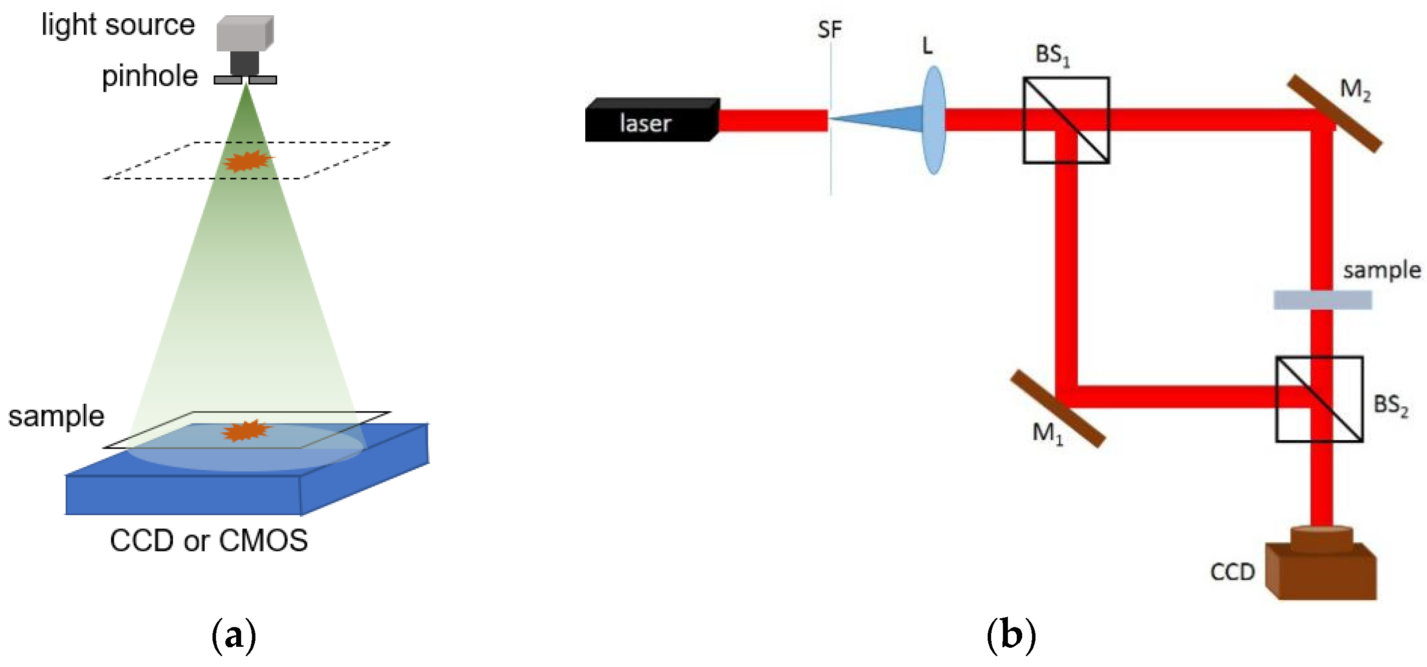
2. Principles of Lensless Digital Holographic Microscopy

The working flow of lensless digital holographic microscopy includes two processes which are hologram recording and image reconstruction. Figure 2 depicts the recording and the reconstruction processes. The recording process is to acquire the interference pattern between the object light and the reference light, and the reconstruction step is to recover the object wave numerically. The Fresnel diffraction [22] method and angular spectrum method [23] are the commonly used methods for reconstruction. Two Fourier transforms are needed for the angular spectrum method in comparison to the one needed by the commonly applied Fresnel diffraction method. The Fresnel diffraction method, however, requires that the distance between the object and the hologram be sufficiently large in comparison to the size of the object or the hologram. The angular spectrum method does not have a lower reconstruction distance limit. Moreover, spurious noise and interference components can be tightly controlled through the analysis and filtering of the angular spectrum [23].

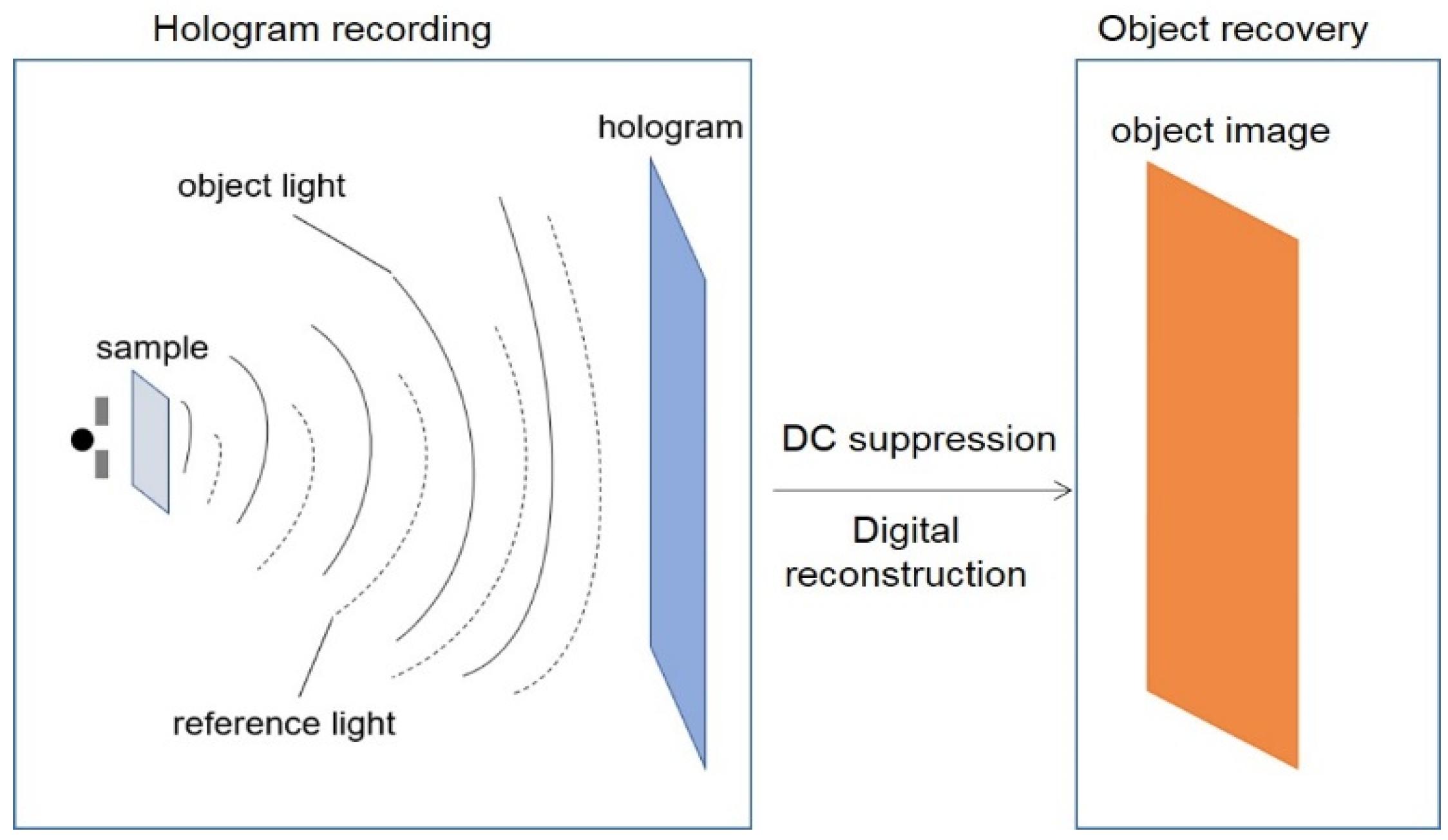
2.1. Hologram Recording

During hologram recording, the object wave carries the object’s information, which can be expressed as:
O ( x , y ) = A 0 ( x , y ) exp ( j 0 ( x , y ) )
where A 0 ( x , y ) represents the amplitude distribution,   0 ( x , y ) is the phase distribution.
The reference light wave is expressed as:
R ( x , y ) = A r ( x , y ) exp ( j r ( x , y ) )
The interference field is the superposition of the object light and reference light. The interference intensity can be expressed as:
I ( x , y ) = | O ( x , y ) + R ( x , y ) | 2 = | A r ( x , y ) | 2 + | A o ( x , y ) | 2 + O * ( x , y ) R ( x , y ) + O ( x , y ) R * ( x , y )
In Equation (4), the first two items are called zero-order noise, which are usually shown in the image plane as background. It can be eliminated by subtracting the background when no samples are placed. The third term is the complex amplitude distribution of the object light field. The last term and the third term are conjugated. Simple back-propagation of Equation (4), after the background subtraction, results in both a focused image and a defocused image of the sample that spatially overlap, and the latter forms what is commonly known as the twin image artifact in inline holography. When the sample is placed rather close to the imaging sensor, this twin image can strongly obscure the real object image, which leads to low signal and background contrast [17].

2.2. Digital Reconstruction

In lensless digital holography, the object light field can be reconstructed by back-propagation. To recover the object light field, the angular spectrum method can be used. This approach consists of computing the Fourier transform of the captured hologram after background subtraction, multiplying it by the transfer function of free space, and then inverse Fourier transforming. Mathematically,
U ( x , y ) = F 1 { F [ I ( x , y ) ] exp [ j k z 1 ( λ f x ) 2 ( λ f y ) 2 ] }
where U ( x , y ) is the reconstructed object light field,   F and F 1 represent the Fourier transform and the inverse Fourier transform, f x ,   f y are the spatial frequencies, and λ is the wavelength.

3. Contrast and Resolution Enhancement

Contrast and resolution are two significant performance metrics of microscopy. Image contrast refers to the magnitude of the gray contrast of the image, which is usually disturbed by the meaningless content in the image. Complex content often affects the useful information in the image. Image resolution is the ability to distinguish adjacent objects. The higher the resolution, the higher the pixel density. The imaging quality of the LDHM is challenged by the twin image and aliasing effects because sensors only respond to intensity and pixels are of finite size. High resolution and contrast are required in biomedical applications. Contrast and resolution improvement has been an open problem since the technique was developed.

3.1. Contrast Improvement

In lensless digital holography, whether the Fresnel diffraction method or angular spectrum method is used for reconstruction, the recovered image is disturbed by the twin image, which decreases the image contrast. This is because only the intensity of the field at the image sensor plane is measured and the field phase information is missing [24]. Furthermore, zero-order noise also reduces image contrast. Several strategies were proposed to remove the zero-order noise and the twin image to increase the image contrast.

3.1.1. HRO and Hologram Normalization

To eliminate the interference of the zero-order noise, a relatively simple method can be used. For an off-axis holographic system, the reference light reaching the detector is occluded before recording the hologram to obtain the intensity distribution of the object. The authors of [25] proposed the Hologram, Reference, Object (HRO) method where the object light is first blocked to obtain the intensity distribution of reference light, then the hologram is recorded. Finally, the hologram without zero-order noise can be obtained by subtracting the object light and the reference light intensity respectively. However, it is difficult to separate the reference light and the object light in the in-line holographic system. As a result, the intensity distribution of the object light and the reference light cannot be obtained separately. A commonly used method is to obtain a background intensity distribution before the sample holograms are recorded. In the reconstruction stage, the hologram is first normalized by dividing the hologram by the background intensity distribution.

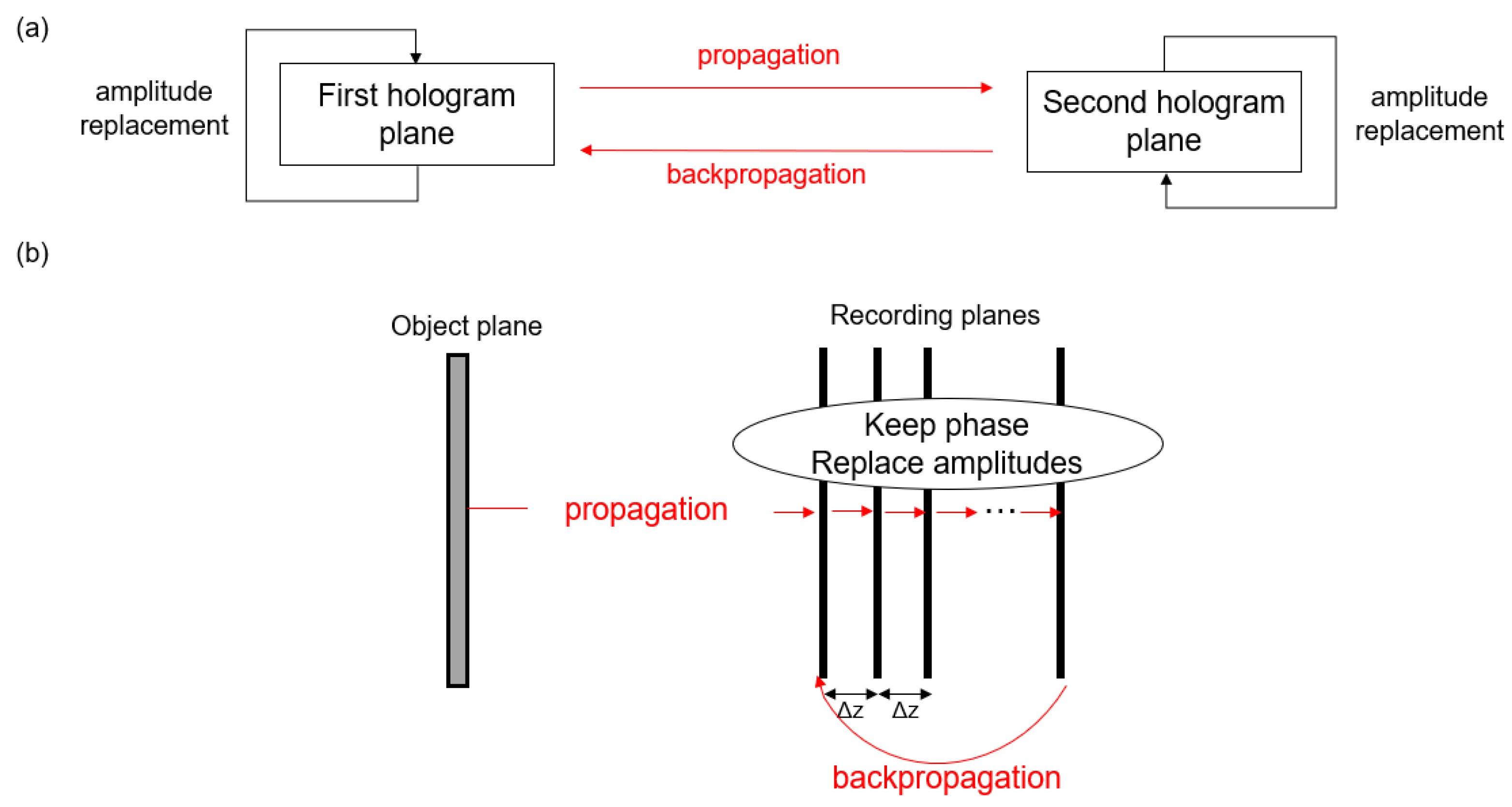
3.1.2. Gerchberg–Saxton Iterative Algorithm

To eliminate the twin images some non-iterative methods have been presented such as averaging holograms of different recording distances [26]. The most popular iterative method is the Gerchberg–Saxton(GS) iterative algorithm [27], which is depicted in Figure 3a, where two recording planes are required. The complex amplitude is obtained by combining the square root of the amplitude of the first recording plane with an initial phase estimation. The angle spectrum theory is utilized for the object wave to propagate to the second recording plane. The phase is maintained and the amplitude is replaced by the square root of the amplitude of the second recording plane to obtain a new complex amplitude. This complex amplitude is then back propagated to the first recording plane. The twin image can be eliminated by repeating the process. As shown in Figure 3b, the multi-height phase iterative algorithm is an improvement on the GS algorithm [28,29], which iterates using eight holograms of different heights, typically 15 μm apart. Usually, it can obtain good results after iterating 10–20 times. Using the transport of intensity equation (TIE) [30,31], a nearly global optimal phase distribution can be obtained. With TIE, not only the locally optimal solution is avoided, but also the convergence is sped up. Considering the positive absorption of an object, the amplitude of the wave front should not be greater than 1 at the object plane [32]. The process of propagating to the object plane is added to the GS iteration, and the portion whose amplitude is greater than 1 is changed to 1, and the corresponding phase becomes 0.

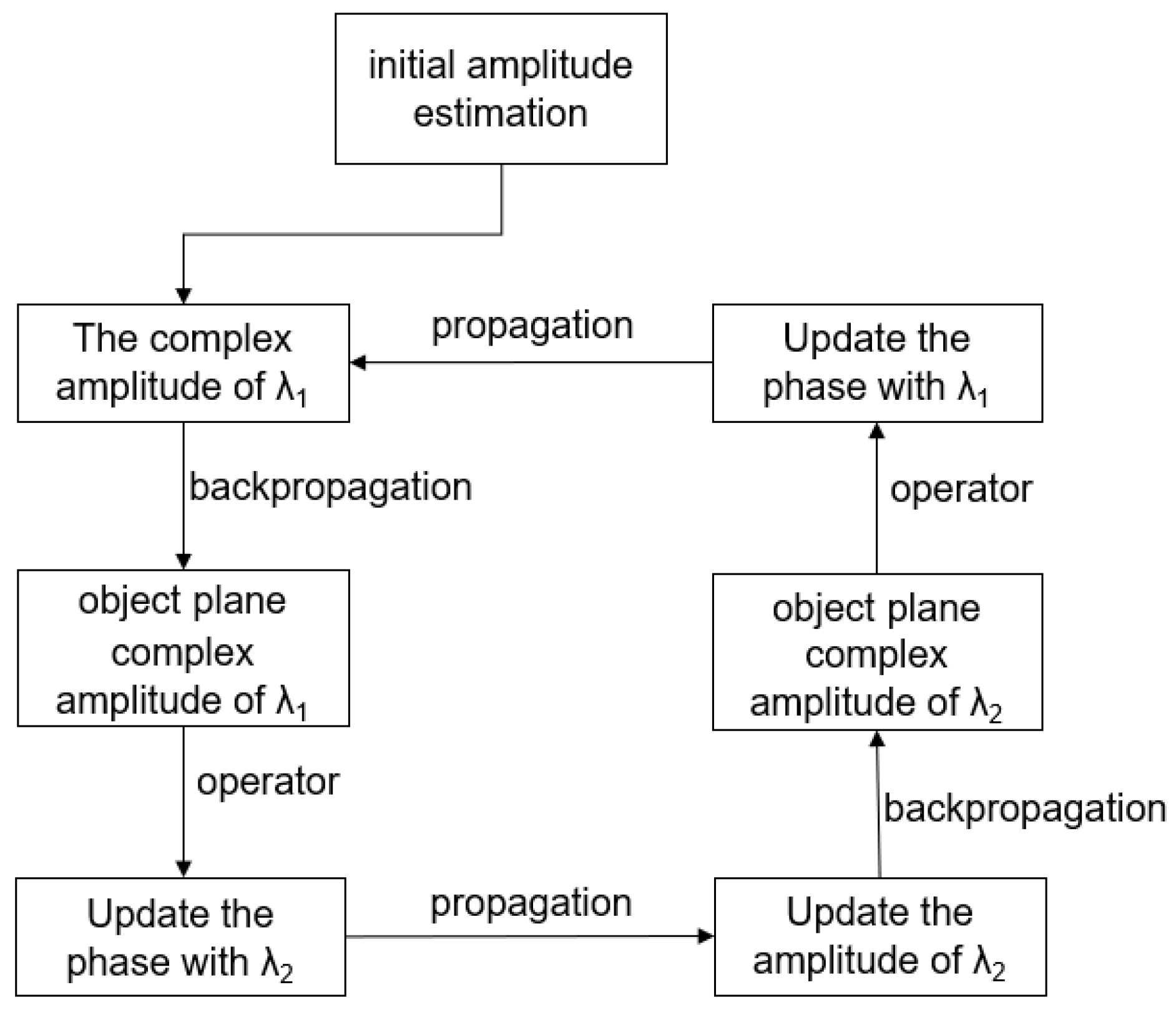
3.1.3. Multiwavelength Phase Retrieval

Recording a set of holograms at different wavelengths is also another widely used method [33,34] to remove the twin image. The estimated amplitude and phase at each wavelength are processed for multiple iterations by the traditional GS algorithm. In the iterative process, assuming that the refractive index of the object and its surrounding medium is constant regardless of the wavelength, the phase of the object at different wavelengths can be expressed as:
1 ( x , y ) / 2 ( x , y ) = λ 2 / λ 1
The dual-wavelength algorithm flow is shown in Figure 4. The initial complex wave is first estimated by combining the square root of amplitude under λ 1 with a random phase. Then the estimated complex wave backpropagates to obtain the complex amplitude of the object plane. After Wiener filtering, the phase is updated according to formula (6) and propagates to the detection plane. The complex amplitude is replaced by the square root of amplitude obtained with λ 2 , which is backpropagated to the object plane, and the phase is updated after Wiener filtering. After several repetitions, the twin image can be effectively removed. This method can be extended to more than two wavelengths.

3.1.4. Phase Retrieval Based on Compressive Sensing

Compressive sensing (CS) is important for generating multidimensional images from low dimensional data. The compressive sensing theory guarantees high-precision reconstruction of multi-channel encoders that meet the conditions of restricted isometry property [35,36]. Assuming that the signal to be reconstructed can be expressed as a sparse function under a certain condition, compressive sensing solves the signal optimization problem [37]. With compressive sensing, holographic images without twin images can be reconstructed [38,39,40]. In addition, by using the sparsity of the sample, the compressive sensing can also improve the resolution of the hologram reconstruction [41], which can solve the interference caused by the twin images and the out-of-focus between different layers in the volume imaging [42]. For the multi-height phase iterative algorithm, only two holograms can be used for phase retrieval under the sparsity condition [43].

3.2. Resolution Enhancement

Lensless digital holographic microscopy allows the imaging FOV to reach the effective area of the entire sensor chip, while high-resolution imaging is also desired. As can be seen from Equation (5), the resolution of the computationally reconstructed image is equal to the resolution of the captured hologram. Because there is no lens with finite NA to limit the resolution, the resolution-limiting factor is: in theory, the refractive index of the medium that fills in the space between the sample and sensor planes; and in practice, the pixel size of the sensor [44]. In this section, we introduce some methods to improve the resolution.

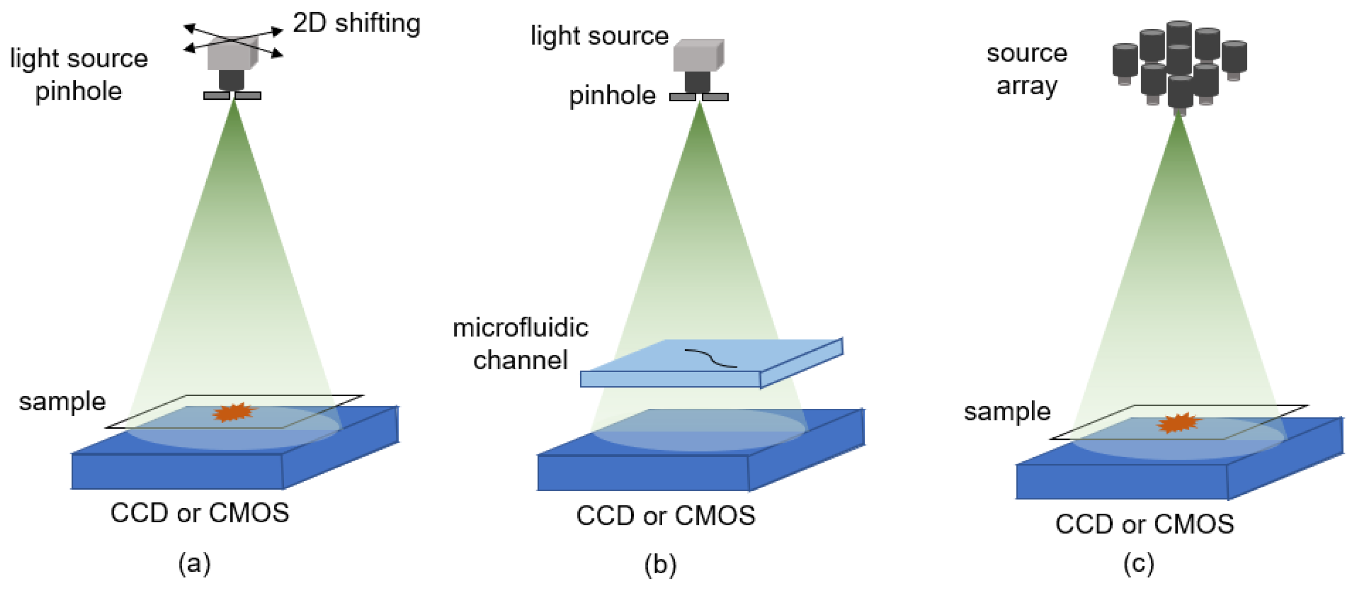
3.2.1. Pixel Super-Resolution Strategy

The resolution of lensless holographic microscopy primarily depends on the pixel size of the sensor chip, resulting in under-sampling of the high-frequency information. In terms of hardware, it is undoubtedly that using a detector with a smaller pixel size increases the spatial resolution. At present, the smallest pixel size of the CMOS sensors is about 1 µm which is not high enough for the microscale biomedical research. Fortunately, the pixel super-resolution algorithm can break through the limitation caused by the hardware pixel size [45]. Usually, the pixel super-resolution algorithm acquires multiple holograms of low resolution to synthesize high-resolution holograms by moving the holograms in sub-pixel increments. Sub-pixel movement between these holograms can be achieved by moving the light source [46], the sample [47], or the detector, as shown in Figure 5. Illuminating the object sequentially by each source in the source array is an equivalent way to realize the source shifting, which is illustrated in Figure 5c [48]. Figure 6 shows the difference between before and after using the pixel super-resolution algorithm. Figure 6b contains more high-frequency information that is not collected in the lower-resolution holograms. The pixel size of the digital hologram is reduced by six times [47] when a 2.2 µm imaging sensor is used. In [49], Gao et al. combined the phase retrieval and pixel super-resolution techniques as a unified optimization problem and proposed a generalized algorithmic framework to solve the problem. Half-pitch resolution is achieved for the experimental data acquired by an imaging sensor with a pixel pitch of 3.8 µm. In [50], four independent linear equations that relate frequency components in four aliased sub-pixel shifted images to unaliased frequency components in a super-resolution image were first derived. Then a predetermined inverse matrix was used to calculate the frequency components of a super-resolution image from those of four under-sampled images. The results show that the proposed non-iterative sub-pixel shifting super-resolution technique that can enhance the resolution of LDH by a factor of two with a 1.67 µm imaging sensor.

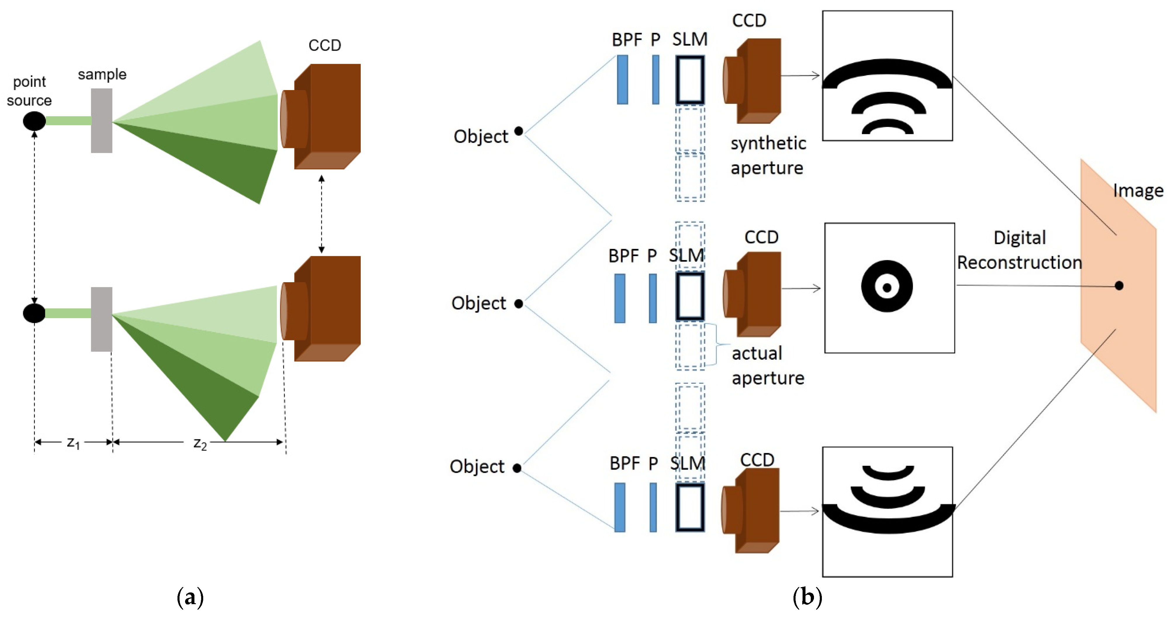
3.2.2. Synthetic Aperture Technology

Synthetic aperture is a well-known super-resolution technique which extends the resolution capabilities of an imaging system beyond the theoretical Rayleigh limit dictated by the system’s actual aperture. Synthetic aperture technology (SA) was first applied to radar [51]. The synthetic aperture is generated by angular multiplexing, which is implemented by tilted beam illumination over the object and allows the recovery of additional spatial frequencies falling outside the digital camera sensible area when on-axis illumination is used. Using this idea, the numerical aperture (NA) of the system can be improved. A typical system setup is shown in Figure 7a [52]. The point source is moved to several off-axis positions to provide different illumination angles. In [53], the authors proposed a lensless system containing a BPF, a polarizer, a spatial light modulator (SLM), and a digital camera. The system is shown in Figure 7b whose effective aperture is three times larger than those used alone. The synthetic aperture was implemented by shifting the BPF-polarizer-SLM-camera set, located across the field of view among several viewpoints. In theory, this configuration can be extended to enlarge the NA by an arbitrary factor. In [54], the superresolution is achieved by linearly moving the inspected object. In [55], the spatial resolution is improved by recording a small number of holograms featuring varying angles of incidence based on the synthetic spectrum normalization. SA was also applied to terahertz in-line digital holography [56] and a one-shot synthetic aperture digital holographic microscopy was proposed by using a combination of angular-multiplexing and coherence gating to achieve super-resolution imaging in a single exposure [57].

3.2.3. Use of SLM

The imaging quality can be improved by adding an SLM to the lensless holographic imaging system. As shown in Figure 8, the SLM behind the laser acts as a phase mask, and the phase modulated beam that passes the SLM illuminates the sample to form holograms on the detector plane. This method can suppress the twin image [58]. At the same position, the SLM is used to generate multiple mask modes to encode the sample information. The sensor records a set of images and then synthesizes images with improved resolution and high SNR [59]. It is worth noting that the sparse phase and amplitude reconstruction (SPAR) algorithm as a phase retrieval method is proposed due to the random phase modulation and some noise with Poisson distribution [60]. In addition, the SLM can also be placed between the object and the detector as denoted by the dotted line in Figure 8. By loading the distribution of the diffraction grating into the SLM, the detector collects more light, including high-frequency information of the object [61]. For example, [62] used an adjustable one-dimensional cosine grating mode to achieve higher resolution.

3.2.4. RGB Multiplexing

The principle of single-exposure super-resolved interferometric microscopy by RGB multiplexing can be considered as the process of encoding and decoding. In the encoding stage, sample information is encoded onto a monochrome sensor [63] or a single-color sensor [64] using beams of different wavelengths in the case of angular multiplexing. During decoding, the complex amplitude of the images is restored after Fourier filtering by adding three coherent reference lights of RGB. A schematic diagram where only one detector is used [65] is illustrated in Figure 9a. Another arrangement is to record the holograms using three detectors. Figure 9b shows the system which is set up as an in-line optical path and two off-axis optical paths [66]. Due to angular multiplexing, holograms at three wavelengths can be subjected to synthetic aperture operations, and Fourier transforms can be used to obtain super-resolution images [67], where the resolution can be enhanced by two times when using a sensor with a pixel size of 6.45 μm.

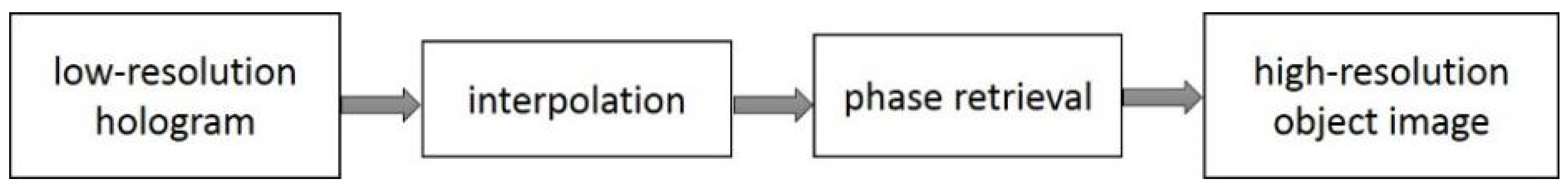
3.2.5. Data Interpolation

In holographic microscopy, interpolation can be used to increase spatial resolution for relatively large sensor pixels [68,69]. According to the Nyquist sampling theorem, interpolation can improve the resolution because of its oversampling process. The hologram is up-sampled to enlarge the size of the matrix; thereby, the pixel size is effectively reduced, which leads to better resolution.
A disadvantage of this method is that the information added to the image is estimated and not completely correct. This process is also affected by the twin image, as the twin image can interfere with image detail. Therefore, combining phase iteration and interpolation can improve image resolution without artifacts [70], which is illustrated in Figure 10. In this algorithm, the optical field is propagated back and forth between the sample plane and the sensor plane while using the measured intensity and a priori information about the sample as constraints, following Gerchberg–Saxton and Fienup’s methods. Before the iteration, the intensity data matrix measured by the sensor is interpolated to enlarge the matrix dimension and thus effectively reduce the pixel size. During the iteration, the sensor plane constraints are applied on only the measured intensity location but not the interpolated data location. The resolution is improved about 1.26 times using a sensor with pixel size of 2.2 μm.

3.2.6. Different Illumination Strategies

If structured light rather than the uniform light is used for illumination, the high spatial frequency components of a sample, which are not accessible in conventional microscopy, are shifted into the detectable domain and thus can be observed because of the Moiré effect and leads to an increased spatial resolution. Thus, the structured illumination microscopy was proposed [71]. Illuminating the sample with a periodic pattern and recording the generated Moiré pattern, the resolution of lensless digital holographic microscopy can also be enhanced through structured light illumination [72]. Figure 11 illustrates a lensless holographic microscopy system based on structured light. The imaging process can be described as follows: the plane wave is used to illuminate the known regular pattern, and after passing through lens 1, the structure pattern is formed on the object plane through diffraction at different angles. After imaging and magnifying by lens 2 to the image plane, the off-axis hologram is generated by interference with the reference light. Structural light illumination can be achieved by adding grating to the system [73,74]. The resolution can be improved by about 1.5 times using an imaging sensor with a pixel size of 2.2 μm. Another solution is to use a spatial light modulator (SLM) instead of grating [75,76]. The pattern of structured light is loaded into SLM to obtain specific illumination, such as circular symmetrical structured light [77].
The resolution of lensless digital holographic microscopy is also affected by the illumination coherence and temporal coherence [78]. In the case of insufficient spatial coherence of the light source, the spatially-extended light source combined with the deconvolution operation can effectively improve the imaging resolution [79]. For insufficient temporal coherence, a differential holographic reconstruction method based on ultra-broadband light source illumination can enhance the resolution and contrast of imaging [80].

3.2.7. Deep Learning

The artificial neural network is a nonlinear computing model based on brain structure. The network is connected by simple nonlinear elements and adaptive weights [81]. When neurons are divided into different layers connected by different weights, a complex training process, such as error backpropagation, is required. Deep learning is a machine learning technology that uses multi-layer neural networks for data modelling, analysis, and decision making, and has been widely used for statistics, analysis, and prediction of large data samples.
In recent years, deep learning has been applied to holographic image reconstruction and phase retrieval to obtain high-resolution images without twin image [82,83]. The deep learning networks can map the relationship between the input and output without any prior knowledge of the imaging model. By training a set of matched low-resolution and high-resolution images, the relationship between them can be learned. Thus, a high-resolution image can be retrieved from one or multiple low-resolution images captured by a similar setup. Compared with other methods, there is no need to change the angle or height in the data acquisition process based on deep learning, which reduces the complexity of the operation. On the other hand, it does not need to use multiple wavelengths of light source or a source array, which reduces the complexity of the system and is more conducive to real-time imaging, even in a bad environment. Whether it is an amplitude object, a phase object or a complex object, it is possible to reconstruct a high-resolution image without prior knowledge based on deep learning [84,85].
Moreover, based on a deep learning framework for the generative adversarial network (GAN), there are breakthroughs in both pixel size limitation and diffraction limit limitation, and image super-resolution is achieved in coherent imaging systems [86]. In addition, combining the volumetric imaging ability of holographic microscopy with artifact-free images of incoherent microscopy, 3D imaging of object snapshots with bright-field contrast using a single hologram is realized based on the GAN network [7]. It should be noted that training in this framework requires a lot of data.

4. Application of Lensless High-Resolution Holographic Microscopy in Biomedicine

With the development of the imaging system and the reconstruction algorithm, high-resolution holographic imaging can be achieved and gradually finds wide applications in biomedicine.

4.1. Molecular Quantitative Analysis

In [87], the LDHM shows great potential in blood analysis. For high-density red blood cells (RBCs), high-resolution imaging is possible, while auto-counting is performed. Moreover, the volume of RBCs is further characterized at the single-cell level, as well as the measurement of hemoglobin concentration in whole blood samples. Combined with the neural network, RBCs can be extracted from the holograms, which helps to quantitatively analyze the morphological characteristics of RBCs to diagnose diseases associated with RBCs [88]. Furthermore, in terms of disease detection, due to the high throughput of lensless holographic microscopy, screening speed can be significantly improved, such as screening of bacillus anthracis spores [89], parasites [90], and cervical cells [91].
Lensless digital holographic microscopy does not require mechanical focus and is characterized by real-time and dynamic imaging [92]. One application for this capability is automatic positioning, tracking, and shape analysis of targets, such as positioning of colloidal particles [93], dynamic tracking of prokaryotes [94], and cells of any shape [95], deformation measurement [96] and quantitative analysis of flowing cells [97], and the analysis of the platelets adhesion morphology, aggregation, and spreading in vitro models [98]. In [99], the tracking of an evaporating droplet (size ∼ 100 µm) and the microscopic imaging of bacteria (size ∼ 1 µm) are also realized by the LDHM. Another application is the measurement of the object size and 3D position, such as a fast-flowing bubble [100] and moving particles [101,102]. Moreover, the technique has been used to detect nanoparticles, biomolecules, and viruses, e.g., for viral load measurements in field settings [103], and even to measure the particulate matter in the air by combining with an impaction-based air sampler [104].
Different angles of illumination in digital holographic imaging can also be used to generate tomographic reconstructions. With the filtered back-projection algorithm, a 3D lensless image of a specimen can be reconstructed. In [105], the lensless holographic tomography was achieved when many light sources were used sequentially from many different angles, from which many holograms are recorded. A single tomogram can be reconstructed from these multiple holograms. This technique was implemented to the image of C. elegans worms in three dimensions and been merged with micro-fluidics to enable tomographic imaging of 3D objects during their flow and combined with a microfluidic device to perform optofluidic holographic tomography [106]. A quantitative phase image contains information about the optical thickness distribution of a specimen where optical thickness means the product of physical thickness and refractive index. By utilizing a tomographic imaging technique, the 3D refractive index distribution was visualized [107].

4.2. Flow Cytometry

Flow cytometry can count and sort tiny particles suspended in fluids for analysis of plankton for many years [108]. This technique relies on the sheath flow to limit the biological sample to the focus of the illumination light, measuring the scattering intensity of each particle within the sample volume. As the digital holographic wavefront can record all the information of the object [109], lensless holographic microscopy proved to be able to image plankton [110] and offers a new option for expensive flow cytometry on the market due to its capability of volumetric imaging. Using the laptop, holographic-based portable flow cytometry can dramatically reduce cost, size, and weight, and provide high-throughput for large samples. With deep learning, the system can monitor a large number of biological samples continuously [111]. In [112], the authors presented a lensless digital in-line holographic microscopy system combining with microfluidic chips for monitoring cells and conducting viability experiments that can be used for space-based in vitro experiments.

4.3. Biomolecular Classification

The classification of biological samples has always been of interest to researchers. The traditional approach requires transferring samples to the lab for testing or testing at a relatively slow rate. Based on lensless digital holographic microscopy, not only can samples be detected in the field, but also the classification speed is fast. The detection of common biological molecules, such as oak pollen, Bermuda grass pollen, ragweed pollen, and aspergillus spores, has a classification accuracy of >94% [113]. Cell classification is also a problem that has attracted much attention. As a label-free and high-throughput method, lensless holographic microscopy can classify white blood cell subpopulations based on cell size and deformability [114]. Using the optical neural network, the classification accuracy of monocytes, granulocytes, and lymphocytes is close to 89% [115,116]. In addition, a passive linear integrated photon stage is utilized as an effective nonlinear hybrid interface between the holographic projection and the image sensor, which enables high-throughput cell classification using multiple parallel channels [117,118]. Combining with deep convolutional neural networks, the label-free holography was applied to discriminate the normal cells from tumour cells and to classify different types of tumour cells [119]. Regarding cell classification, Buzalewicz et al. in [120] used LDHM to obtain new optical signatures of bacterial colonies, which represents an innovative approach to bacterial colony analysis.
Recently, the Mach–Zehnder based DHM was used to measure the cell volume [121], quantify cytotoxic effect of organic nanoparticles [122], investigate morphological changes in T-lymphocytes after exposure with bacterial determinants for early detection of septic conditions [123], and detect leukocyte alternations associated with perioperative inflammation after cardiac surgery [124]. It is believed that the LDHM can be applied to these fields soon.

5. Outlook

The image resolution of lensless digital holographic microscopy is mainly limited by the pixel size of the CMOS or CCD sensors. With the continuous development of industrial technology, hardware performance will be enhanced. This means that the computer will run faster and the sensor technology will be more advanced. Lensless holographic microscopes can achieve higher resolution from hardware. In addition, in order to break through the resolution limitations of the lensless holographic microscope, pixel super-resolution algorithms and synthetic aperture techniques have matured. The use of SLM or some improvement of lighting strategies can also improve the resolution. On the other hand, the rapid development of artificial intelligence will benefit the reconstruction of super-resolution images, and the cost of time will decrease by using GPUs for calculation. The reviewed resolution enhancement techniques are shown in Table 1. The exemplary results show that the pixel super-resolution method obtains the best result, which is about several hundred nanometers when the hologram is imaged by a sensor with a pixel size of 2.2 μm. In this approach, sub-pixel movement between the holograms is needed which can be achieved by moving the light source, the sample, or the detector. The illumination strategies are used by the synthetic aperture and the structured light to enlarge the NA. A diffraction grating is inserted between the sample and the camera when the SLM is used. These methods can achieve a resolution improvement factor ranging from 1.26 to 2.5. Extra hardware configuration is necessary except the data interpolation and deep learning method. In general, the hardware updating methods perform better than the data processing counterpart, though the implementation of the former ones is more complicated.
Lensless holographic microscopy has a wide application in biomedicine fields, such as flow cytometry, disease monitoring, and classification of cells. As the lensless holographic microscope is more portable and can be operated by tablets and smartphones, it can be a reliable choice for areas where resources are limited.
The improved imaging resolution of the lensless holographic microscope is bound to sacrifice another degree of freedom, which is time. Computation time is an important parameter. How to obtain higher resolution images with faster speed is a problem that needs to be considered. The rapid high-resolution reconstruction methods will make the lensless digital holographic microscope more suitable for biomedical applications.

Author Contributions

Conceptualization, D.C. and X.C.; resources, X.L.; writing—original draft preparation, D.C.; writing—review and editing, L.W. and H.X.; funding acquisition, D.C. and X.C. All authors have read and agreed to the published version of the manuscript.

Funding

This work was supported in part by the National Natural Science Foundation of China (81871397, 81627807); the National Young Talent Program; the Shaanxi Science Fund for Distinguished Young Scholars (No. 2020JC-27), the Key Research and Development Program of Shaanxi (2021ZDLSF04-05), the Shaanxi Young Top-notch Talent Program, the Fundamental Research Funds for Central Universities (QTZX2105), the National Key R&D Program of China (2018YFC0910600), and the and the Fundamental Research Funds for Central Universities (JB211211).

Institutional Review Board Statement

Not applicable.

Informed Consent Statement

Not applicable.

Conflicts of Interest

The authors declare no conflict of interest.

References

  1. Bardell, D. The Biologists’ Forum: The Invention of the Microscopy. Bios 2004, 75, 18–20. [Google Scholar] [CrossRef]
  2. Huang, T.S. Digital holography. Proc. IEEE 1971, 59, 1335–1346. [Google Scholar] [CrossRef]
  3. Pavillon, N.; Kühn, J.; Moratal, C.; Jourdain, P.; Depeursinge, C.; Magistretti, P.J.; Marquet, P. Early Cell Death Detection with Digital Holographic Microscopy. PLoS ONE 2012, 7, e30912. [Google Scholar] [CrossRef]
  4. Pavillon, N.; Kühn, J.; PJourdain Depeursinge, C.; Magistretti, P.J.; Marquet, P. Cell Death and Ionic Regulation Detection with Digital Holographic Microscopy. In Digital Holography and Three-Dimensional Imaging; Optical Society of America: Washington, DC, USA, 2011; p. DTuC25. [Google Scholar]
  5. Zeng, Y.; Lu, J.; Hu, X.; Chang, X.; Sun, Q. Axial displacement measurement with high resolution of particle movement based on compound digital holographic microscopy. Opt. Commun. 2020, 475, 126300. [Google Scholar] [CrossRef]
  6. El-Schich, Z.; Leida Mölder, A.; Gjörloff Wingren, A. Quantitative Phase Imaging for Label-Free Analysis of Cancer Cells—Focus on Digital Holographic Microscopy. Appl. Sci. 2018, 8, 1027. [Google Scholar] [CrossRef] [Green Version]
  7. Wu, Y.; Luo, Y.; Chaudhari, G.; Rivenson, Y.; Calis, A.; de Haan, K.; Ozcan, A.A. Bright-field holography: Cross-modality deep learning enables snapshot 3D imaging with bright-field contrast using a single hologram. Light Sci. Appl. 2019, 8, 25. [Google Scholar] [CrossRef] [Green Version]
  8. Pedrini, G.; Fröning, P.; Fessler, H.; Tiziani, H.J. In-line digital holographic interferometry. Appl. Opt. 1998, 37, 6262–6269. [Google Scholar] [CrossRef] [PubMed]
  9. Mudanyali, O.; Oztoprak, C.; Tseng, D.; Erlinger, A.; Ozcan, A. Detection of waterborne parasites using field-portable and cost-effective lensfree microscopy. Lab Chip 2010, 10, 2419–2423. [Google Scholar] [CrossRef] [Green Version]
  10. Cuche, E.; Marquet, P.; Depeursinge, C. Spatial filtering for zero-order and twin-image elimination in digital off-axis holography. Appl. Opt. 2000, 39, 4070–4075. [Google Scholar] [CrossRef]
  11. Liebling, M.; Blu, T.; Unser, M. Complex-wave retrieval from a single off-axis hologram. JOSA A 2004, 21, 367–377. [Google Scholar] [CrossRef] [Green Version]
  12. Sencan, I.; Coskun, A.F.; Sikora, U.; Ozcan, A. Spectral demultiplexing in holographic and fluorescent on-chip microscopy. Sci. Rep. 2014, 4, 3760. [Google Scholar] [CrossRef] [Green Version]
  13. Latychevskaia, T.; Fink, H. Solution to the twin image problem in holography. Phys. Rev. Lett. 2007, 98, 233901. [Google Scholar] [CrossRef] [PubMed] [Green Version]
  14. Greenbaum, A.; Luo, W.; Su, T.W.; Gorocs, Z.; Xue, L.; Isikman, S.O.; Coskun, A.F.; Mudanyali, O.; Ozcan, A. Imaging without lenses: Achievements and remaining challenges of wide-field on-chip microscopy. Nat. Methods 2012, 9, 889–895. [Google Scholar] [CrossRef] [PubMed]
  15. Mudanyali, O.; Tseng, D.; Oh, C.; Isikman, S.O.; Sencan, I.; Bishara, W.; Oztoprak, C.; Seo, S.K.; Khademhosseini, B.; Ozcan, A. Compact, light-weight and cost-effective microscopy based on lensless incoherent holography for telemedicine applications. Lab Chip 2010, 10, 1417–1428. [Google Scholar] [CrossRef] [PubMed] [Green Version]
  16. Luo, W.; Shabbir, F.; Gong, C.; Gulec, C.; Pigeon, J.; Shaw, J.; Greenbaum, A.; Tochitsky, S.; Joshi, C.; Ozcan, A. High throughput on-chip analysis of high-energy charged particle tracks using lensfree imaging. Appl. Phys. Lett. 2015, 106, 151107. [Google Scholar] [CrossRef]
  17. Wu, Y.; Ozcan, A. Lensless digital holographic microscopy and its applications in biomedicine and environmental monitoring. Methods 2018, 136, 4–16. [Google Scholar] [CrossRef]
  18. Garcia-Sucerquia, J.; Xu, W.; Jericho, S.K.; Klages, P.; Jericho, M.H.; Kreuzer, H.J. Digital in-line holographic microscopy. Opt. Lett. 2006, 45, 836–850. [Google Scholar] [CrossRef]
  19. Carlos, T.; Jorge, G.S. Numerical dark field illumination applied to experimental digital lensless holographic microscopy for reconstructions with enhanced contrast. Opt. Lett. 2018, 43, 4096–4099. [Google Scholar]
  20. Mendoza-Yero, O.; Tajahuerce, E.; Lancis, J.; Garcia-Sucerquia, J. Diffractive digital lensless holographic microscopy with fine spectral tuning. Opt. Lett. 2013, 38, 2107–2109. [Google Scholar] [CrossRef] [Green Version]
  21. Nicola, S.D.; Ferraro, P.; Finizio, A.; Pierattini, G. Wave front reconstruction of Fresnel off-axis holograms with compensation of aberrations by means of phase-shifting digital holography. Opt. Lasers Eng. 2002, 37, 331–340. [Google Scholar] [CrossRef]
  22. Schnars, U.; Jüptner, W.P.O. Digital recording and numerical reconstruction of holograms. Meas. Sci. Technol. 2002, 13, R85–R101. [Google Scholar] [CrossRef]
  23. Mann, C.J.; Kim, M.K. Quantitative phase-contrast microscopy by angular spectrum digital holography. SPIE 2006, 6090, 60900B. [Google Scholar]
  24. Loïc, D.; Fournier, C.; Fournel, T.; Ducottet, C. Twin-image noise reduction by phase retrieval in in-line digital holography. SPIE 2005, 5914, 59140J. [Google Scholar]
  25. Menesesfabian, C.; Rodriguezzurita, G.; Víctor, A. Optical tomography of transparent objects with phase-shifting interferometry and stepwise-shifted ronchi ruling. JOSA A 2006, 23, 298–305. [Google Scholar] [CrossRef] [PubMed]
  26. Arapov, Y.D.; Dvornichenko, M.E.; Kamenev, V.G.; Turkin, V.N. Reconstruction of Digital in-line Holograms and Suppression of the Twin-image in Gabor Holography. Sens. Transducers 2019, 233, 40–45. [Google Scholar]
  27. Fienup, J.R. Phase retrieval algorithms: A comparison. Appl. Opt. 1982, 21, 2758–2769. [Google Scholar] [CrossRef] [Green Version]
  28. Greenbaum, A.; Ozcan, A. Maskless imaging of dense samples using pixel super-resolution based multi-height lensfree on-chip microscopy. Opt. Express. 2012, 20, 3129–3143. [Google Scholar] [CrossRef]
  29. Greenbaum, A.; Zhang, Y.; Feizi, A.; Chung, P.; Luo, W.; Kandukuri, S.R.; Ozcan, A. Wide-field computational imaging of pathology slides using lens-free on-chip microscopy. Sci. Transl. Med. 2014, 6, 267ra175. [Google Scholar] [CrossRef]
  30. Guo, Y.; Fang, Z.; Qiang, S.; Jing, Z. Application of hybrid iterative algorithm in tie phase retrieval with large defocusing distance. Acta Opt. Sin. 2016, 36, 0912001. [Google Scholar]
  31. Zhou, W.; Guan, X.; Liu, F.; Yu, Y.; Zhang, H.; Poon, T.C.; Banerjee, P.P. Phase retrieval based on transport of intensity and digital holography. Appl. Opt. 2018, 57, A229–A234. [Google Scholar] [CrossRef]
  32. Lu, R.; Feng, P.; Wen, X.; Li, Y.; Wang, F. Twin image elimination from two in-line holograms via phase retrieval. Chin. Opt. Lett. 2012, 10, 0902. [Google Scholar]
  33. Barton, J.J. Removing multiple scattering and twin images from holographic images. Phys. Rev. Lett. 1991, 67, 3106–3109. [Google Scholar] [CrossRef] [PubMed] [Green Version]
  34. Zhang, H.; Stangner, T.; Wiklund, K.; Andersson, M. Object plane detection and phase retrieval from single-shot holograms using multi-wavelength in-line holography. Appl. Opt. 2018, 57, 9855–9862. [Google Scholar] [CrossRef] [PubMed] [Green Version]
  35. Emmanuel, J.; Candès Romberg, J.K.; Tao, T. Stable Signal Recovery from Incomplete and Inaccurate Measurements. Commun. Pure Appl. Math. 2006, 59, 1207–1223. [Google Scholar]
  36. Candes, E.J.; Tao, T. Near-Optimal Signal Recovery from Random Projections: Universal Encoding Strategies? IEEE Trans. Inf. Theory 2006, 52, 5406–5425. [Google Scholar] [CrossRef] [Green Version]
  37. Boyd, V.; Vandenberghe, L. Faybusovich, “Convex optimization”. IEEE Trans. Automat. Contr. 2006, 51, 1859. [Google Scholar]
  38. Weng, J.; Yang, C.; Qin, Y.; Hai, L. LED-based digital hologram reconstruction by compressive sensing. SPIE 2015, 9675, 967505. [Google Scholar]
  39. Zhang, W.; Cao, L.; Brady, D.J.; Zhang, H.; Cang, J.; Zhang, H.; Jin, G. Twin-Image-Free Holography: A Compressive Sensing Approach. Phys. Rev. Lett. 2018, 121, 093902. [Google Scholar] [CrossRef] [PubMed]
  40. Souza, J.C.; Freire, R.B.R.; Santos, P.A.M. Compressive holography with resolution improvement and lensless adjustable magnification. Opt. Commun. 2019, 437, 337–341. [Google Scholar] [CrossRef]
  41. Hua, L.; Xie, G.; Shaw, D.T.; Scott, P.D. Resolution enhancement in digital in-line holography. SPIE 1991, 1385, 142–151. [Google Scholar]
  42. Zhang, W.; Zhang, H.; David, J.; Jin, G.; Cao, L. Compressive depth-resolved holographic microscopy. In Digital Holography and Three-Dimensional Imaging; Optical Society of America: Washington, DC, USA, 2019; p. Th3A.8. [Google Scholar]
  43. Rivenson, Y.; Wu, Y.; Wang, H.; Zhang, Y.; Feizi, A.; Ozcan, A. Sparsity-based multi-height phase recovery in holographic microscopy. Sci. Rep. 2018, 6, 37862. [Google Scholar] [CrossRef] [PubMed] [Green Version]
  44. Ozcan, A.; McLeod, E. Lensless imaging and sensing. Annu. Rev. Biomed. Eng. 2016, 18, 77–102. [Google Scholar] [CrossRef] [PubMed] [Green Version]
  45. Farsiu, S.; Robinson, M.D.; Elad, M.; Milanfar, P. Fast and robust multiframe super resolution. IEEE Trans. Image. Process. 2004, 13, 1327–1344. [Google Scholar] [CrossRef]
  46. Greenbaum, A.; Luo, W.; Khademhosseinieh, B.; Su, T.W.; Coskun, A.F.; Ozcan, A. Increased space-bandwidth product in pixel super-resolved lensfree on-chip microscopy. Sci. Rep. 2013, 3, 1717. [Google Scholar] [CrossRef]
  47. Bishara, W.; Zhu, H.; Ozcan, A. Holographic opto-fluidic microscopy. Opt. Express. 2010, 18, 27499–27510. [Google Scholar] [CrossRef] [PubMed]
  48. Bishara, W.; Sikora, U.; Mudanyali, O.; Su, T.; Yaglidere, O.; Luckhart, S.; Ozcan, A. Holographic pixel super-resolution in portable lensless on-chip microscopy using a fiber-optic array. Lab Chip 2010, 11, 1276–1279. [Google Scholar] [CrossRef]
  49. Gao, Y.; Cao, L. Generalized optimization framework for pixel super-resolution imaging in digital holography. Opt. Express 2021, 29, 28805–28823. [Google Scholar] [CrossRef] [PubMed]
  50. Lee, H.; Kim, J.; Kim, J.; Jeon, P.; Lee, S.A.; Kim, D. Noniterative sub-pixel shifting super-resolution lensless digital holography. Opt. Express 2021, 29, 29996–30006. [Google Scholar] [CrossRef]
  51. Curlander, J.C.; McDonough, R.N. Synthetic Aperture Radar; John Wiley and Sons: New York, NY, USA, 1991. [Google Scholar]
  52. Vicente, M.; Zalevsky, Z. Superresolved digital in-line holographic microscopy for high-resolution lensless biological imaging. J. Biomed. Opt. 2010, 15, 046027. [Google Scholar]
  53. Barak, K.; Joseph, R. Super-resolution in incoherent optical imaging using synthetic aperture with Fresnel elements. Opt. Express 2010, 18, 962–972. [Google Scholar]
  54. Ferreira, C.; García, J.; Micó, V. Surpassing digital holography limits by lensless object scanning holography. Opt. Express 2012, 20, 9382. [Google Scholar]
  55. Lai, X.; Tu, H.; Wu, H.; Lin, Y.; Cheng, J. Resolution enhancement of spectrum normalization in synthetic aperture digital holographic microscopy. Appl. Opt. 2015, 54, 51–58. [Google Scholar] [CrossRef]
  56. Huang, H.; Rong, L.; Wang, D.; Li, W.; Deng, Q.; Li, B.; Wang, Y.; Zhan, Z.; Wang, X.; Wu, D. Synthetic aperture in terahertz in-line digital holography for resolution enhancement. Appl. Opt. 2016, 55, A43–A48. [Google Scholar] [CrossRef] [PubMed]
  57. Lin, Y.; Tu, H.; Wu, X.; Lai, X.; Cheng, C. One-shot synthetic aperture digital holographic microscopy with non-coplanar angular-multiplexing and coherence gating. Opt. Express 2018, 26, 12620–12631. [Google Scholar] [CrossRef] [PubMed]
  58. Bernet, S.; Harm, W.; Jesacher, A.; Ritsch-Marte, M. Lensless digital holography with diffuse illumination through a pseudo-random phase mask. Opt. Express 2011, 19, 25113–25124. [Google Scholar] [CrossRef] [PubMed]
  59. Hussain, A.; Li, Y.; Liu, D.; Kuang, C.; Xu, L. Lensless imaging through multiple phase patterns illumination. J. Biomed. Opt. 2017, 22, 110502. [Google Scholar] [CrossRef] [PubMed]
  60. Katkovnik, V.; Shevkunov, I.; Petrov, N.V.; Egiazarian, K. Computational wavelength resolution for in-line lensless holography: Phase-coded diffraction patterns and wavefront group-sparsity. SPIE 2017, 10335, 033509. [Google Scholar]
  61. Li, B.; Wang, D.; Wang, Y.; Rong, L. High-resolution digital holographic imaging by using a spatial light modulator. SPIE 2017, 9282, 92820N. [Google Scholar]
  62. Lin, Q.; Wang, D.; Wang, Y.; Rong, L.; Chang, S. Super-resolution imaging in digital holography by using dynamic grating with a spatial light modulator. Opt. Lasers Eng. 2015, 66, 279–284. [Google Scholar] [CrossRef]
  63. Calabuig, A.; Ferreira, C.; Garcia, J.; Zalevsky, Z.; Mico, V. Resolution improvement by single-exposure superresolved interferometric microscopy with a monochrome sensor. JOSA A 2011, 28, 2346–2358. [Google Scholar] [CrossRef]
  64. Ferraro, P.; Grilli, S.; Ritsch-Marte, M.; Stifter, D.; Sanz, M.; Picazo-Bueno, J.A.; Garcia, J.; Mico, V. Multi-illumination Gabor holography recorded in a single camera snap-shot for high-resolution phase retrieval in digital in-line holographic microscopy. SPIE 2015, 9529, 95290B. [Google Scholar]
  65. Calabuig, A.; Micó, V.; Garcia, J.; Zalevsky, Z.; Ferreira, C. Single-exposure super-resolved interferometric microscopy by red-green-blue multiplexing. Opt. Lett. 2011, 36, 885–887. [Google Scholar] [CrossRef] [PubMed]
  66. Granero, L.; Ferreira, C.; Zalevsky, Z.; Garcia, J.; Mico, V. Single-exposure super-resolved interferometric microscopy by RGB multiplexing in lensless configuration. Opt. Lasers Eng. 2016, 82, 104–112. [Google Scholar] [CrossRef]
  67. Granero, L.; Ferreira, C.; Garcia, J. Lensless single-exposure super-resolved interferometric microscopy. SPIE 2013, 8788, 878808. [Google Scholar]
  68. Podorov, S.G.; Bishop, A.I.; Paganin, D.M.; Pavlov, K.M. Re-sampling of inline holographic images for improved reconstruction resolution. arXiv 2009, arXiv:0911. 0520. [Google Scholar]
  69. Tahara, T.; Awatsuji, Y.; Kaneko, A.; Koyama, T.; Nishio, K.; Ura, S.; Matoba, K. Parallel two-step phase-shifting digital holography using polarization. Opt. Rev. 2010, 17, 108–113. [Google Scholar] [CrossRef]
  70. Wang, M.; Wu, J. Iterative digital in-line holographic reconstruction with improved resolution by data interpolation. SPIE 2014, 9271, 927110. [Google Scholar]
  71. Neil, M.A.A.; Juškaitis, R.; Wilson, T. Method of obtaining optical sectioning by using structured light in a conventional microscopy. Opt. Lett. 1997, 22, 1905–1907. [Google Scholar] [CrossRef]
  72. Lai, X.; Tu, H.; Lin, Y.; Cheng, C. Structured illumination induced moiré fringes for resolution enhancement in digital holographic microscopy. In Digital Holography and Three-Dimensional Imaging; Optical Society of America: Washington, DC, USA, 2016; p. DT4G.4. [Google Scholar]
  73. Ma, J.; Yuan, C.; Situ, G.; Pedrini, G.; Osten, W. Resolution enhancement in digital holographic microscopy with structured illumination. Chin. Opt. Lett. 2013, 11, 090901. [Google Scholar]
  74. Feng, S.; Wang, M.; Wu, J. Enhanced resolution for amplitude object in lensless inline holographic microscopy with grating illumination. Opt. Eng. 2017, 56, 093107. [Google Scholar] [CrossRef]
  75. Gao, P.; Pedrini, G.; Osten, W. Structured illumination for resolution enhancement and autofocusing in digital holographic microscopy. Opt. Lett. 2013, 38, 1328–1330. [Google Scholar] [CrossRef] [PubMed]
  76. Ganjkhani, Y.; Charsooghi, M.A.; Akhlaghi, E.A.; Moradi, A. Super-resolved Mirau digital holography by structured illumination. Opt. Commun. 2017, 404, 110–117. [Google Scholar] [CrossRef]
  77. Ma, J.; Yin, Y.; Su, P. Radial super-resolution in digital holographic microscopy using structured illumination with circular symmetry. SPIE 2018, 10616, 1061603. [Google Scholar]
  78. Greenbaum, A.; Akbari, N.; Feizi, A.; Wei, L.; Ozcan, A. Field-Portable Pixel Super-Resolution Color Microscopy. PLoS ONE 2013, 8, e76475. [Google Scholar] [CrossRef] [Green Version]
  79. Feng, S.; Wu, J. Resolution enhancement method for lensless in-line holographic microscopy with spatially-extended light source. Opt. Express 2017, 25, 24735–24744. [Google Scholar] [CrossRef] [PubMed]
  80. Shaodong, F.; Jigang, W. Differential holographic reconstruction for lensless in-line holographic microscopy with ultra-broadband light source illumination. Opt. Commun. 2019, 430, 9–13. [Google Scholar]
  81. Wagner, K.H. Deep optical learning devices and architectures. In Proceedings of the IEEE Photonics Society Summer Topical Meeting Series (SUM), Newport Beach, CA, USA, 11–13 July 2016; p. 16263439. [Google Scholar]
  82. Rivenson, Y.; Zhang, Y.; Gunaydin, H.; Da, T.; Ozcan, A. Phase recovery and holographic image reconstruction using deep learning in neural networks. Light Sci. Appl. 2017, 7, 17141. [Google Scholar] [CrossRef]
  83. Wu, Y.; Rivenson, Y.; Zhang, Y.; Wei, Z.; Gunaydin, H.; Lin, X.; Ozcan, A. Extended depth-of-field in holographic image reconstruction using deep learning based auto-focusing and phase-recovery. Optica 2018, 6, 704–710. [Google Scholar] [CrossRef] [Green Version]
  84. Gong, Z.; Tian, G.; Shen, Z.; Wang, X.; Hu, T.; Wang, D.; He, Y.; Xie, N. Fast phase retrieval in off-axis digital holographic microscopy through deep learning. Opt. Express 2018, 26, 19388–19405. [Google Scholar]
  85. Ren, Z.; Xu, Z.; Edmund, Y.M. End-to-end deep learning framework for digital holographic reconstruction. SPIE 2019, 1, 016004. [Google Scholar] [CrossRef]
  86. Liu, T.; De Haan, K.; Rivenson, Y.; Wei, Z.; Zeng, X.; Zhang, Y.; Ozcan, A. Deep learning-based super-resolution in coherent imaging systems. Sci. Rep. 2019, 9, 3926. [Google Scholar] [CrossRef] [Green Version]
  87. Seo, S.; Isikman, S.O.; Sencan, I.; Mudanyali, O.; Su, T.; Bishara, W.; Erlinger, A.; Ozcan, A. High-Throughput Lens-Free Blood Analysis on a Chip. Anal. Chem. 2010, 82, 4621–4627. [Google Scholar] [CrossRef] [PubMed] [Green Version]
  88. Yi, F.; Moon, I.; Javidi, B. Automated red blood cells extraction from holographic images using fully convolutional neural networks. Biomed. Opt. Express 2017, 8, 4466–4479. [Google Scholar] [CrossRef] [Green Version]
  89. Jo, Y.J.; Park, S.; Jung, J.H.; Yoon, J.; Park, Y.K. Holographic deep learning for rapid optical screening of anthrax spores. Sci. Adv. 2017, 3, e1700606. [Google Scholar] [CrossRef] [PubMed] [Green Version]
  90. Zhang, Y.B.; Koydemir, H.C.; Shimogawa, M.M.; Yalcin, S.; Guziak, A.; Liu, T.; Oguz, I.; Huang, Y.; Bai, B.; Luo, Y.; et al. Motility-based label-free detection of parasites in bodily fluids using holographic speckle analysis and deep learning. Light Sci. Appl. 2018, 7, 108. [Google Scholar] [CrossRef]
  91. Mangal, J.; Monga, R.; Mathur, S.R.; Dinda, A.K.; Khare, K. Unsupervised organization of cervical cells using high resolution digital holographic microscopy. arXiv 2018, arXiv:1811.05214. [Google Scholar]
  92. Zikmund, T.; Kvasnica, L.; Tyc, M.; Krizova, A.; Collakova, J.; Chmelik, R. Sequential processing of quantitative phase images for the study of cell behaviour in real-time digital holographic microscopy. J. Microsc. 2014, 256, 117–125. [Google Scholar] [CrossRef]
  93. Hannel, M.D.; Abdulali, A.; O’Brien, M.; Grier, D.G. Machine-learning techniques for fast and accurate feature localization in holograms of colloidal particles. Opt. Express 2018, 26, 15221–15231. [Google Scholar] [CrossRef] [PubMed] [Green Version]
  94. Serabyn, E.; Liewer, K.; Lindensmith, C.; Kent, W.; Jay, N. Compact, lensless digital holographic microscopy for remote microbiology. Opt. Express 2016, 24, 28540–28548. [Google Scholar] [CrossRef] [PubMed]
  95. Langehanenberg, P.; Ivanova, L.; Bernhardt, I.; Ketelhut, S.; Vollmer, A.; Dirksen, D. Automated three-dimensional tracking of living cells by digital holographic microscopy. J. Biomed. Opt. 2009, 14, 014018. [Google Scholar] [CrossRef]
  96. Xiao, W.; Wang, O.; Pan, F.; Cao, R.; Yi, X. Unlabeled flow cellular deformation measurement based on digital holographic microscopy. SPIE 2018, 10749, 107490L. [Google Scholar]
  97. Langehanenberg, P.; Bally, G.V.; Kemper, B. Autofocusing in digital holographic microscopy. 3D Res. 2011, 2, 4. [Google Scholar] [CrossRef]
  98. Boudejltia, K.Z.; Daniel, R.D.S.; Uzureau, P.; Yourassowsky, C.; David, P.M.; Guy, C.; Chopard, B.; Frank, D. Quantitative analysis of platelets aggregates in 3D by digital holographic microscopy. Biomed. Opt. Express 2015, 6, 3556–3563. [Google Scholar] [CrossRef] [PubMed] [Green Version]
  99. Jolivet, F.; Momey, F.; Denis, L.; Méès, L.; Faure, N.; Grosjean, N.; Pinston, F.; Marié, J.L.; Fournier, C. Regularized reconstruction of absorbing and phase objects from a single in-line hologram, application to fluid mechanics and micro-biology. Opt. Express 2018, 26, 8923–8940. [Google Scholar] [CrossRef] [PubMed] [Green Version]
  100. Barbastathis, G.; José, A.; Domínguez-Caballero, J.A.; Barbastathis, G. Quantitative measurement of size and three-dimensional position of fast-moving bubbles in air-water mixture flows using digital holography. Appl. Opt. 2010, 49, 1549. [Google Scholar]
  101. Loïc, D.; Fournier, C.; Fournel, T.; Ducottet, C.; Jeulin, D. Direct extraction of the mean particle size from a digital hologram. Appl. Opt. 2008, 45, 944–952. [Google Scholar]
  102. Dubois, F.; Callens, N.; Yourassowsky, C.; Hoyos, M.; Kurowski, P.; Monnom, O. Digital holographic microscopy with reduced spatial coherence for three-dimensional particle flow analysis. Appl. Opt. 2006, 45, 864–871. [Google Scholar] [CrossRef]
  103. Ray, A.; Li, S.; Segura, T.; Ozcan, A. High-throughput quantification of nanoparticle degradation using computational microscopy and itsapplication to drug delivery nanocapsules. ACS Photonics 2017, 4, 1216–1224. [Google Scholar] [CrossRef]
  104. Wu, Y.; Shiledar, A.; Li, Y.; Wong, J.; Feng, S.; Chen, X.; Chen, C.; Jin, K.; Janamian, S.; Yang, Z.; et al. Air quality monitoring using mobile microscopy and machine learning. Light Sci. Appl. 2017, 6, e17046. [Google Scholar] [CrossRef]
  105. Isikman, S.O.; Bishara, W.; Sikora, U.; Yaglidere, O.; Yeah, J.; Ozcan, A. Field-portable lensfree tomographic microscope. Lab Chip 2011, 11, 2222–2230. [Google Scholar] [CrossRef] [Green Version]
  106. Isikman, S.O.; Bishara, W.; Zhu, H.; Ozcan, A. Optofluidic tomography on a chip. Appl. Phys. Lett. 2011, 98, 161109. [Google Scholar] [CrossRef] [PubMed] [Green Version]
  107. Bian, Y.; Zhang, Y.; Yin, P.; Li, H.; Ozcan, A. Optical refractometry using lensless holography and autofocusing. Opt. Express 2018, 26, 29614–29628. [Google Scholar] [CrossRef] [PubMed]
  108. Trask, B.J.; Engh, G.J.V.D.; Elgershuizen, J.H.B.W. Analysis of phytoplankton by flow cytometry. Cytom. A 1982, 2, 258–264. [Google Scholar] [CrossRef] [PubMed]
  109. Dominguez-Caballero, J.A.; Loomis, N.; Li, W. Advances in Plankton Imaging Using Digital Holography. In Digital Holography and Three-Dimensional Imaging; Optical Society of America: Washington, DC, USA, 2007; p. DMB5. [Google Scholar]
  110. Merola, F.; Memmolo, P.; Miccio, L.; Savoia, R.; Mugnano, M.; Fontana, A.; D’Ippolito, G.; Sardo, A.; Iolascon, A.; Gambale, A.; et al. Tomographic flow cytometry by digital holography. Light Sci. Appl. 2016, 6, e16241. [Google Scholar] [CrossRef] [PubMed] [Green Version]
  111. Gorocs, Z.; Tamamitsu, M.; Bianco, V.; Wolf, P.; Roy, S.; Shindo, K.; Yanny, K.; Wu, Y.; Koydemir, H.C.; Rivenson, Y.; et al. A deep learning-enabled portable imaging flow cytometer for cost-effective, high-throughput, and label-free analysis of natural water samples. Light Sci. Appl. 2018, 7, 66. [Google Scholar] [CrossRef]
  112. Delikoyun, K.; Cine, E.; Anil-Inevi, M.; Ozuysal, M.; Tekin, H.C. Lensless Digital in-Line Holographic Microscopy for Space Biotechnology Applications. In Proceedings of the IEEE 9th International Conference on Recent Advances in Space Technologies, Istanbul, Turkey, 11–14 June 2019. [Google Scholar]
  113. Wu, Y.C.; Ayfer, C.; Yi, L.; Chen, C.; Lutton, M.; Rivenson, Y.; Lin, X.; Koydemir, H.C.; Zhang, Y.; Wang, H.; et al. Label-free bio-aerosol sensing using mobile microscopy and deep learning. Rights Permis. 2018, 5, 4617–4627. [Google Scholar]
  114. Holmes, D.; Whyte, G.; Bailey, J.; Vergara-Irigaray, N.; Ekpenyong, A.; Guck, J.; Duke, T. Separation of blood cells with differing deformability using deterministic lateral displacement. Interface Focus 2014, 4, 20140011. [Google Scholar] [CrossRef] [Green Version]
  115. Schneider, B.; Vanmeerbeeck, G.; Stahl, R.; Lagae, L.; Dambre, J.; Bienstman, P. Neural network for blood cell classification in a holographic microscopy system. In Proceedings of the IEEE 17th International Conference on Transparent Optical Networks, Budapest, Hungary, 5–9 July 2015; pp. 1–4. [Google Scholar]
  116. Schneider, B.; Vanmeerbeeck, G.; Stahl, R.; Lagae, L.; Bienstman, P. Using neural networks for high-speed blood cell classification in a holographic-microscopy flow-cytometry system. SPIE 2015, 9328, 93281F. [Google Scholar]
  117. Lugnan, A.; Dambre, J.; Bienstman, P. Integrated pillar scatterers for speeding up classification of cell holograms. Opt. Express 2017, 25, 30526–30538. [Google Scholar] [CrossRef]
  118. Lugnan, A.; Dambre, J.; Bienstman, P. Integrated dielectric scatterers for fast optical classification of biological cells. Neuro-Inspir. Photonic Comput. Workshop 2018, 10689, 1068907. [Google Scholar]
  119. Chen, D.; Wang, Z.; Chen, K.; Zeng, Q.; Wang, L.; Xu, X.; Liang, J.; Chen, X. Classification of unlabelled cells using lensless digital holographic images and deep neural networks. Quant. Imaging Med. Surg. 2021, 11, 4137–4148. [Google Scholar] [CrossRef] [PubMed]
  120. Buzalewicz, I.; Kujawińska, M.; Krauze, W.; Podbielska, H. Novel Perspectives on the Characterization of Species-Dependent Optical Signatures of Bacterial Colonies by Digital Holography. PLoS ONE 2016, 11, e0150449. [Google Scholar] [CrossRef] [PubMed] [Green Version]
  121. Ling, H.; Sridhar, K.; Gollapudi, S.; Kumar, J.; Kumar, J.; Ohgami, R.S. Measurement of cell volume using in-line digital holography. Microscopy 2021, 70, 333–339. [Google Scholar] [CrossRef] [PubMed]
  122. Eder, K.M.; Marzi, A.; Barroso, Á.; Ketelhut, S.; Kemper, B.; Schnekenburger, J. Label-Free Digital Holographic Microscopy for In Vitro Cytotoxic Effect Quantification of Organic Nanoparticles. Cells 2022, 11, 644. [Google Scholar] [CrossRef]
  123. Vom Werth, K.L.; Wörmann, T.; Kemper, B.; Kümpers, P.; Kampmeier, S.; Mellmann, A. Investigating Morphological Changes of T-lymphocytes after Exposure with Bacterial Determinants for Early Detection of Septic Conditions. Microorganisms 2022, 10, 391. [Google Scholar] [CrossRef]
  124. Steike, D.R.; Hessler, M.; Korsching, E.; Lehmann, F.; Schmidt, C.; Ertmer, C.; Schnekenburger, J.; Eich, H.T.; Kemper, B.; Greve, B. Digital holographic microscopy for label-free detection of leukocyte alternations associated with perioperative inflammation after cardiac surgery. Cells 2022, 11, 755. [Google Scholar] [CrossRef]
Figure 1. In-line digital holography schematic. (a) Lensless in-line holographic system schematic. (b) Mach–Zehnder interferometer-based holographic system schematic.
Photonics 09 00358 g001
Figure 2. Schematic diagram of the principle of lensless digital holographic microscopy.
Photonics 09 00358 g002
Figure 3. Diagram of iterative phase recovery algorithm. (a) Gerchberg–Saxton iterative phase retrieval. (b) Multi-height iterative phase retrieval.
Photonics 09 00358 g003
Figure 4. The two-wavelength iterative algorithm flow.
Photonics 09 00358 g004
Figure 5. Pixel super-resolution schematic. (a) Source shifting. (b) Sample shifting. (c) Equivalent to source shifting.
Photonics 09 00358 g005
Figure 6. Pixel super-resolution hologram comparison [47]. (a) Before pixel super-resolution. (b) After pixel super-resolution.
Photonics 09 00358 g006
Figure 7. Synthetic aperture systems. (a) Typical SA system, adapted from [53]. (b) A SA setup where NA can be enlarged by three times. BPF: Band-pass filter, P: polarizer, adapted from [54].
Photonics 09 00358 g007
Figure 8. The system setup of resolution enhancement based on SLM.
Photonics 09 00358 g008
Figure 9. Schematic diagrams of single-exposure super-resolved interferometric microscopy. (a) Single-exposure super-resolved interferometric microscopy with one detector, adapted from [65]. (b) Single-exposure super-resolved interferometric microscopy with three detectors, adapted from [66].
Photonics 09 00358 g009
Figure 10. Schematic diagram of the data interpolation method.
Photonics 09 00358 g010
Figure 11. Schematic diagram of the resolution enhancement in lensless digital holographic microscopy based on structured illumination.
Photonics 09 00358 g011
Table 1. Characteristics of various resolution enhancement techniques.
TechniqueConfigurationPhaseImprovement (Times)
Pixel super-resolution [46,47,48,49,50]Single light source or source arrayNot required6
Synthetic aperture [52,53,54,55,56,57]Single channel or three channelsRequired, by SLM~1.5
SLM-based [58,59,60,61,62]Single channelRequired, by SLM~2
RGB multiplexing [63,64,65,66,67]Three channelsNot required2.5
Data interpolation [68,69,70]NoneNot required~1.26
Structured light [71,72,73,74,75,76,77]Single channelRequired, by SLM~1.5
Spatially-extended light [79]Single channelNot requiredNot given
Deep learning [7,82,83,84,85,86]NoneNot requiredDiffraction limited
Publisher’s Note: MDPI stays neutral with regard to jurisdictional claims in published maps and institutional affiliations.

