Article

Characteristic Study of Non-Line-of-Sight Scattering Ultraviolet Communication System at Small Elevation Angle

1
State Key Laboratory of Integrated Optoelectronics, Institute of Semiconductors, Chinese Academy of Sciences, Beijing 100083, China
2
School of Electronic, Electrical and Communication Engineering, University of Chinese Academy of Sciences, Beijing 100049, China
*
Author to whom correspondence should be addressed.
Submission received: 5 April 2022 / Revised: 14 May 2022 / Accepted: 18 May 2022 / Published: 23 May 2022
(This article belongs to the Section Optical Communication and Network)

Abstract

:
Ultraviolet (UV) communication is considered an effective complement to traditional wireless communication. However, the scattering models of existing non-line-of-sight (NLOS) UV, which are complex, are difficult to combine with the test. In this paper, the single scattering isosceles model with a small elevation angle is proposed first. Then, the relationships between the path loss of single scattering isosceles and elevation angle, emission beam angle, receiving field angle, and transmission distance are studied. Finally, we consider outdoor NLOS UV solar-blind communications test at ranges of up to 100 m and 400 m, with different transmit and receive elevation angles. The results show that the isosceles model is in good agreement with the experiments. In addition, the UV isosceles model exhibits good properties compared with the existing scattering model. The proposed UV isosceles model can be employed as a reference for practical applications in outdoor tests.

1. Introduction

Rapidly evolving semiconductor lasers and light-emitting diode devices, capable of operating more and more efficiently in solar-blind conditions, have brought casual ultraviolet “solar-blind zone” (200~280 nm) communication to the fore again. Ultraviolet (UV) communication in the “solar-blind zone” has characteristics that other signal light sources do not have, such as low background noise, strong scattering, powerful antijamming capability, and high confidentiality [1,2]. These advantages have made UV communication an attractive research area. Researchers have developed a number of propagation models which perfected the theoretical system of non-line-of-sight (NLOS) UV communication.
The single-scattering channel model based on the prolate ellipsoid coordinate system was presented [3,4]. Because of the multiple factors considered [4], many scholars refer to it as a “standard analysis” model. To deal with a more general case, the literature [5] proposed a noncoplanar geometric model in which the transmitter and receiver can point in any direction. For systematic simplicity, some researchers have developed a simple closed-form expression for single scattering path loss in noncoplanar geometries [6]. Further noncoplanar model studies were given [7,8,9]. Subsequently, the Monte Carlo (MC) multiple scattering model was constructed [10] and further developed in [11,12] to cope with the case of long-range UV communication. Based on the MC model, UV communication is intensively studied in system design and signal detection [13,14,15]. To reduce the path loss, a reflection-assisted model based on the MC method was proposed in [16]. The influences of various atmospheric particles were studied in [17]. Considering the coplanar case, the authors of [18] studied the effect of atmospheric parameters on the UV communication rate, while Xu et al. [19] equates the volume of the common scatterer to the volume of the truncated cone, which frees the calculation of the link loss from the cumbersome limitation of the integral. A model that facilitates numerical integration was proposed by [20], which outperforms the MC method in terms of the validity of results and computational time. A single-scattering model that used the cut and complement method to find the volume of the common scatterer was presented [21]. Some experiments based on the single-scattering model were given in [22,23,24]. The performance comparison of several single-scattering models is given in [25]. However, in the existing single-scattering models, there is less attention to the effect of different elevation angles on the model. Although the properties of elevation angles are analyzed in [24], not all elevation angles are applicable to this model. In addition, existing studies on the effect of changing elevation angles on the applicability of the model have rarely been reported.
In this paper, we improve the previous single-scattering model to investigate the model’s applicability at small elevation angles. The calculation of the common scattering volume is reconsidered, and its calculation process is simplified. In addition, we analyze the performance of the isosceles model and the classical model after changing the elevation angle, the field of view, and distance. Moreover, we simulate and analyze the applicability of the isosceles model with the change of elevation angle. Finally, an outdoor UV scattering communication experimental system is built based on a field-programmable gate array (FPGA) to simulate the isosceles model and test the path loss. The experimental results are in good agreement with the simulation results.
The remainder of this paper is organized as follows: In Section 2, the classical single-scattering model is introduced, and the isosceles single model is analyzed in detail. In Section 3, simulations analyze the applicability of the isosceles model. In Section 4, an outdoor test rig was built to verify the accuracy of the isosceles model. Finally, we draw conclusions in Section 5.

2. Non-Line-of-Sight UV Single-Scattering Model

A schematic diagram of the NLOS single scattering model is given in Figure 1 and shows θ 1 the transmitter (Tx) apex angles between the transmitting axis and the horizontal axis, θ 2 the receiver (Rx) apex angles between the receiving axis and the horizontal axis, ϕ 2 , the Rx field of view (FOV), and ϕ 1 , the transmit full beam angle. The Tx and Rx baseline separated by r, and the path r 1 is defined as the distance from Tx to the scattering center. Similarly, the distance from the scattering center to the Rx is defined by r 2   while   θ s is the scattering angle between the light source glows forward direction and the receiver observation direction. The transmitter beam and the receiver FOV overlapping cones define a common scattering volume V.

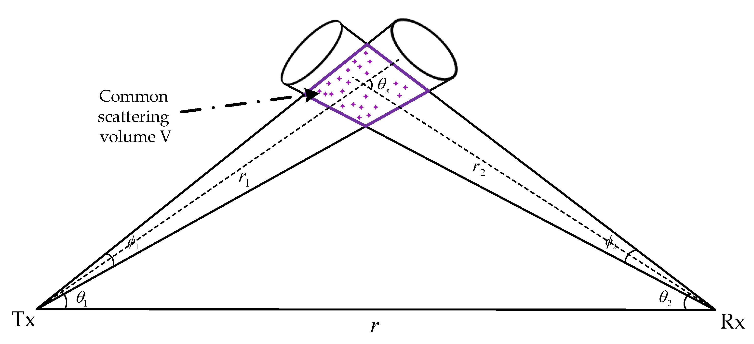
2.1. Classical Single Scattering Model

We denote the classical single-scattering model in [19] by the “CSS” model. Following [19], the path loss for the approximation is modeled as:
L 96 r sin θ 1 sin 2 θ 2 ( 1 cos ϕ 1 2 ) exp [ k e r ( sin θ 1 + sin θ 2 ) sin ( θ s ) ] k s P ( μ ) A r ϕ 1 2 ϕ 2 sin θ s ( 12 sin 2 θ 2 + ϕ 2 2 sin 2 θ 1 )
where k e = k s + k a , k e means the extinction coefficient of the atmosphere, and it is determined by the scattering coefficients k s and absorption coefficients k a . In addition, θ s = θ 1 + θ 2 . P ( μ ) is defined as the scattering probability density function, which is modeled as a weighted sum of the Rayleigh (molecular) and Mie (aerosol) scattering phase functions and is given by [26]:
P ( μ ) = k s R k s p R ( μ ) + k s M k s p M ( μ ) ,
where μ = cos θ s and k s = k s R + k s M , and k s R and k s M are defined as the Rayleigh and Mie scattering coefficients, respectively. The Rayleigh phase function and generalized Henyey–Greenstein function are used to approximate the Rayleigh and Mie scattering phase function [26,27], respectively:
p R ( μ ) = 3 [ 1 + 3 γ + ( 1 γ ) μ 2 ] 16 π ( 1 + 2 γ ) ,
p M ( μ ) = 1 g 2 4 π [ 1 ( 1 + g 2 2 g μ ) 3 / 2 + f 0.5 ( 3 μ 2 1 ) ( 1 + g 2 ) 3 / 2 ]
where γ , g , and f are model parameters.

2.2. Isosceles Single-Scattering Model

The UV communication system is built on a small elevation angle; the NLOS link can be approximated by an isosceles model. In other words, when the elevation angles of the transmitter and receiver are not very large, with one elevation angle fixed and the other slowly changing, we can approximate such a system as an isosceles model with two elevation angles changing simultaneously. We denote the cut and complement model [21] by the “CAC” model, and according to the “CAC” model in [21], the path loss is given by
L 2 π r 4 sin 2 θ 1 sin 2 θ 2 ( 1 cos ϕ 1 2 ) exp [ k e r ( sin θ 1 + sin θ 2 ) sin θ s ] k s P ( u ) A r V sin 4 θ s
where V is given by
V = π 3 tan 2 ( ϕ 1 2 ) { [ r 1 + r 2 tan ( ϕ 2 / 2 ) ( tan θ s + tan ( ϕ 2 / 2 ) ) cos θ s ] 3 [ r 1 r 1 sin ( ϕ 2 / 2 ) sin ( θ s ( ϕ 2 / 2 ) ) ] 3 }
The isosceles model is depicted in Figure 1. We performed the isosceles approximation based on the “CAC” model, so the elevation angles of the receiver and transmitter are equal ( θ 1 = θ 2 ). Therefore, r 2 = r 1 = ( r cos θ 1 ) / 2   , or r 2 = r 1 = ( r cos θ 2 ) / 2 . We only need to choose one angle of the isosceles triangle because the link is symmetrical in the case of isosceles. By choosing θ 1 to bring into the calculation, substituting r 2 and r 1 into Equation (6), and then substituting r 2 , r 1 , and V into Equation (5), the path loss under the isosceles model is expressed as
L 2 r 4 sin 4 θ 1 π ( 1 cos ϕ 1 2 ) exp ( k e r ( 2 sin θ 1 ) sin 2 θ 1 ) k s P ( u ) A r V sin 4 2 θ 1
where V is
V = π r 3 24 cos 3 θ 1 tan 2 ( ϕ 1 2 ) { [ 1 + tan ( ϕ 2 / 2 ) ( tan ( 2 θ 1 ) + tan ( ϕ 2 / 2 ) ) cos ( 2 θ 1 ) ] 3 [ 1 sin ( ϕ 2 / 2 ) sin ( 2 θ 1 ( ϕ 2 / 2 ) ) ] 3 }

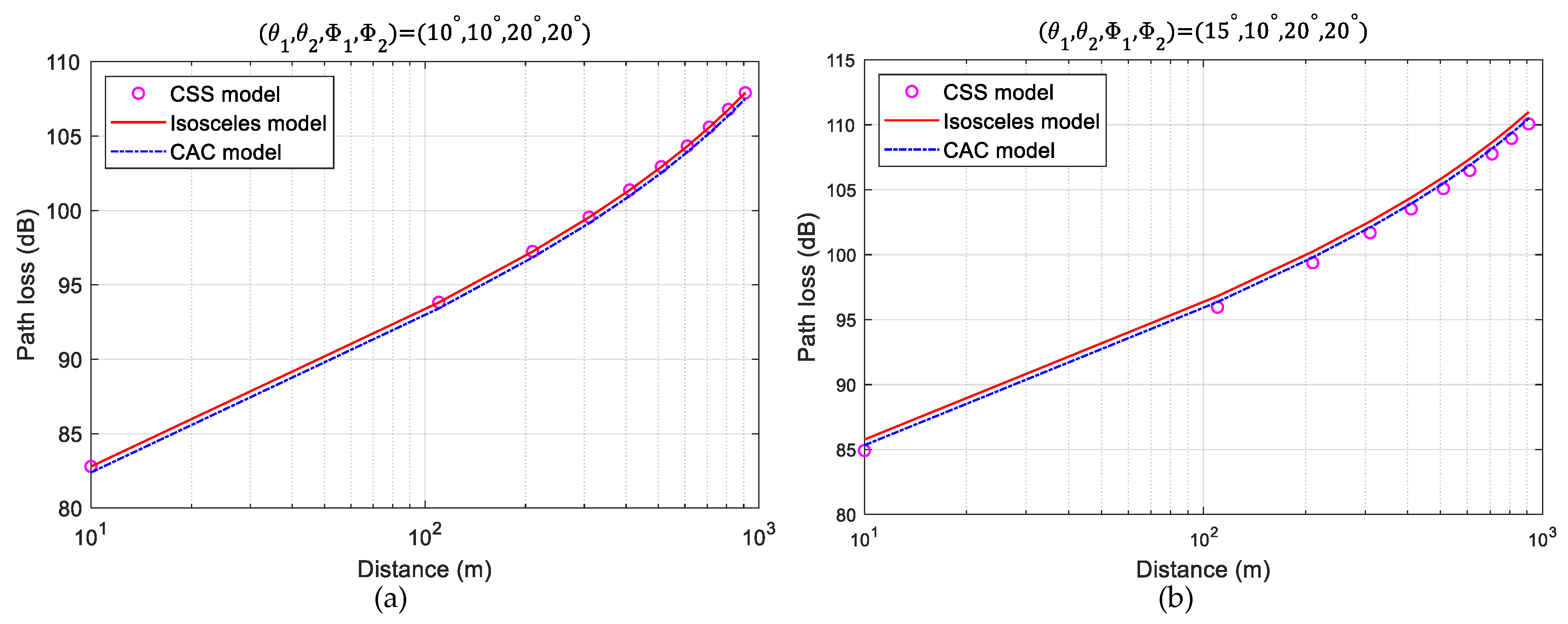
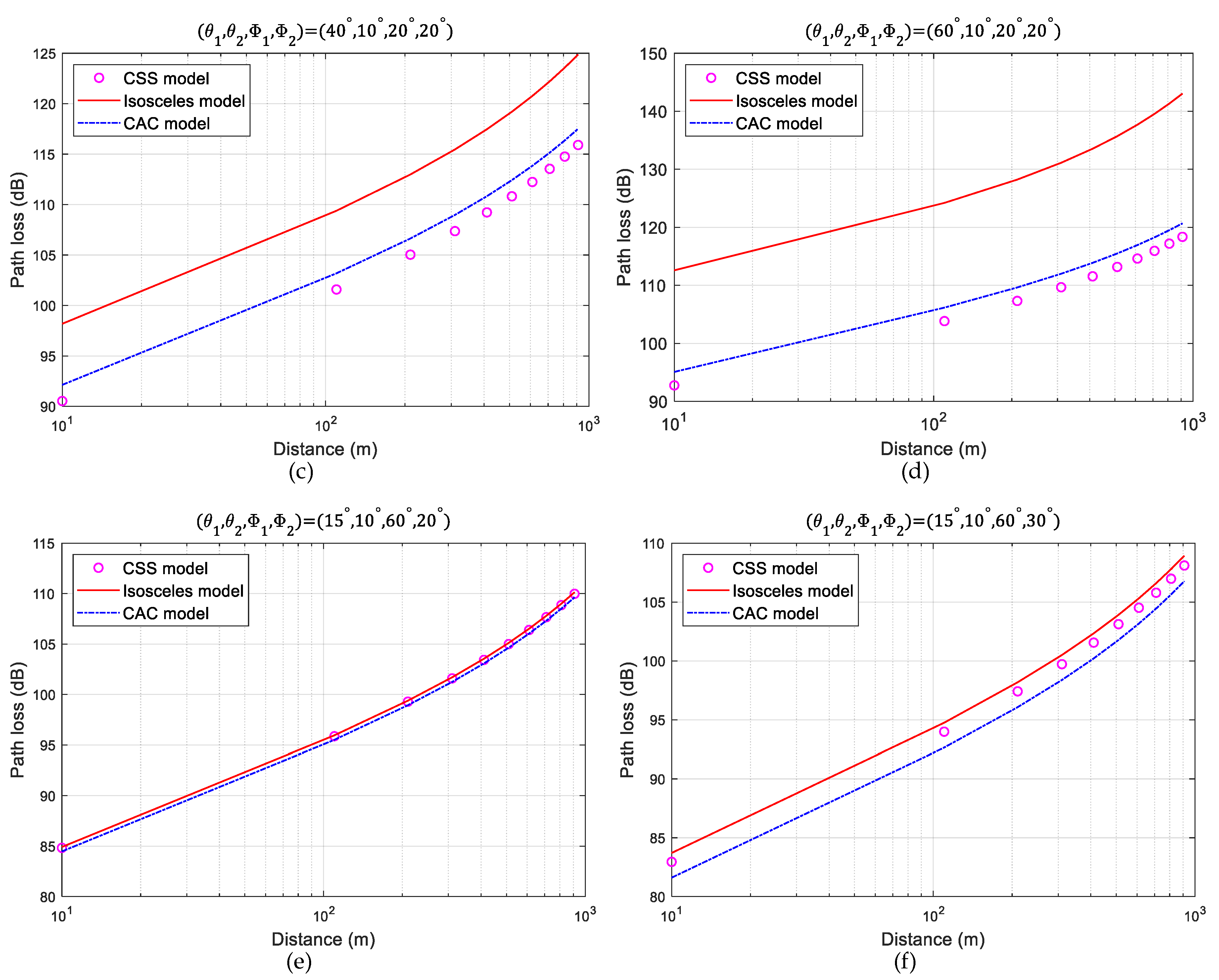
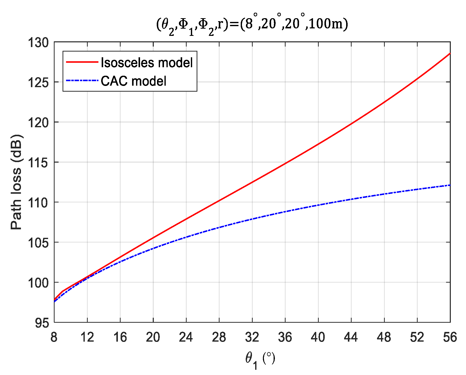
3. Simulation Analysis

In this section, we focus on the accuracy and applicability of the isosceles single-scattering model.
According to the path loss formula of the isosceles single model, the path loss mainly depends on the baseline distance and elevation angle from the common scattering area to the transceiver. To compare the isosceles single-scattering model, we also simulated the “CSS” model and the “CAC” model. The influence of complex air environments such as atmospheric turbulence and multiple scattering are not considered. We assume that the maximum baseline distance between Tx and Rx is 1 km, and the UV wavelength λ is set to 260 nm. At the same time, the Rx effective detection area A r is set to 1.77   cm 2 , ( k a , k s R , k s R ) = ( 0.9 ,   0.24 ,   0.25 )   km 1 . Other simulation parameters are γ = 0.017 [27], g = 0.72 , and f = 0.5 [26].
As shown in Figure 2a,b, when the elevation angle is small, regardless of whether the two elevation angles are equal or not, changing the baseline distance, the isosceles model is in good agreement with the “CSS” and “CAC” models. This indicates that the path loss is insensitive to elevation angle changes when the elevation angles of the transmitter and receiver are small. Figure 2b,c, show that the gap among the “CSS”, the “CAC”, and the isosceles model gradually increases as the transmitter elevation angle increases. When the Tx elevation angle is 60°, as shown in Figure 2d, the error between the isosceles model and the “CAC” model reaches 12 dB; it shows that when the elevation angle of the transceiver becomes larger, the isosceles model will exceed the applicable range. The isosceles model exhibits the same accuracy as the “CSS” and “CAC” models as shown in Figure 2e,f, where, when ϕ 1 is changed, it has little effect on the isosceles model, but when ϕ 2 is changed, the path loss of the isosceles model has a significant change. It shows that the path loss is less dependent on ϕ 1 but shows a strong sensitivity to ϕ 2 . The reason for this phenomenon is that the photons emitted by the transmitter move randomly, and the size of ϕ 2 determines the number of randomly moving photons received at the receiver, which will affect the path loss.
The effect of the transceiver elevation angle on the isosceles model is further quantitatively analyzed. As shown in Figure 3, when the elevation angle is less than 24°, the path loss of the isosceles model and the “CAC” model are very similar. However, as the elevation angle continues to increase, the difference in path loss between the isosceles model and the “CAC” model gradually becomes more significant because the model is developed based on the small angle, and the applicability of the isosceles model becomes worse when the elevation angle gradually becomes larger.

4. Experiment Analysis

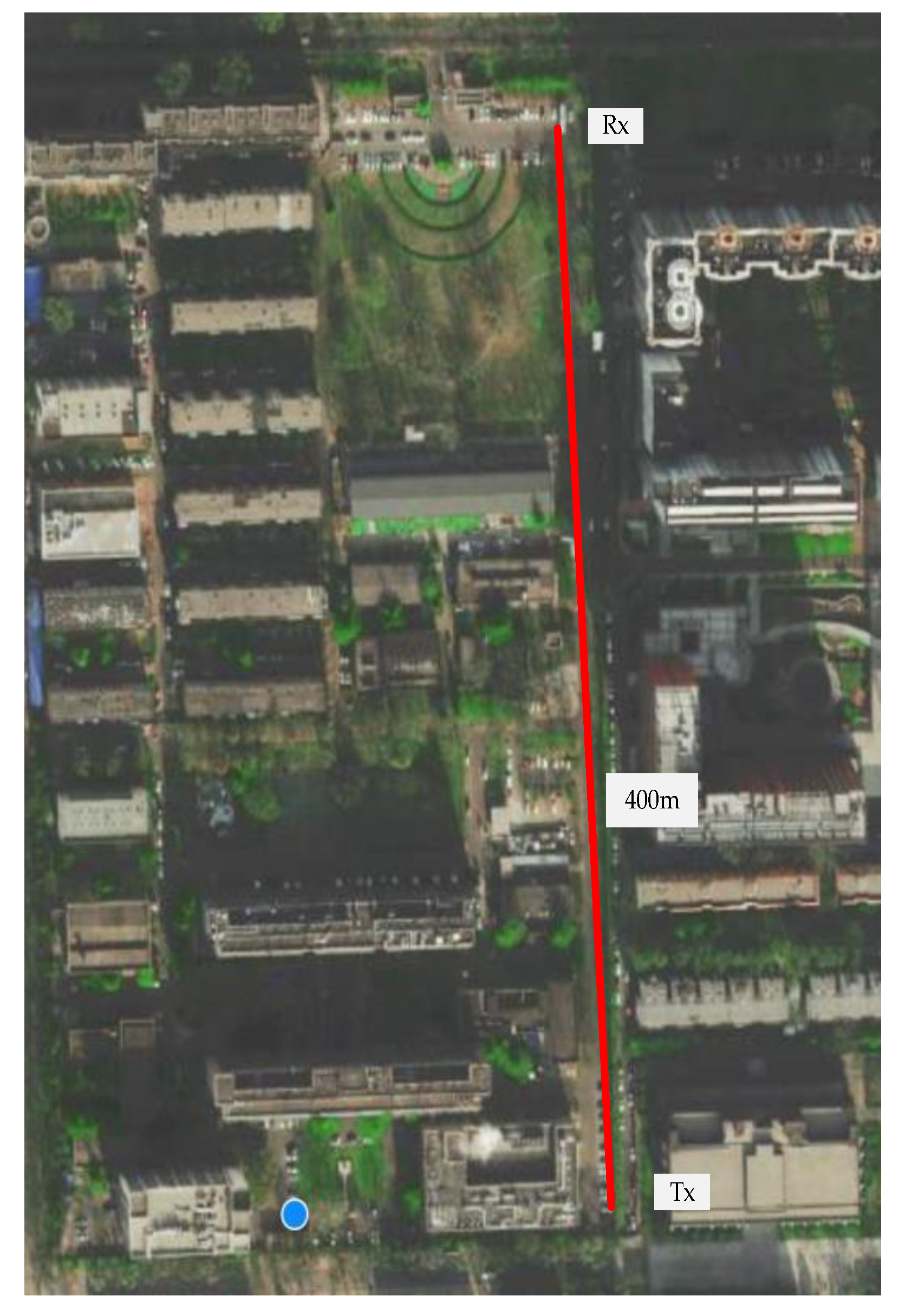
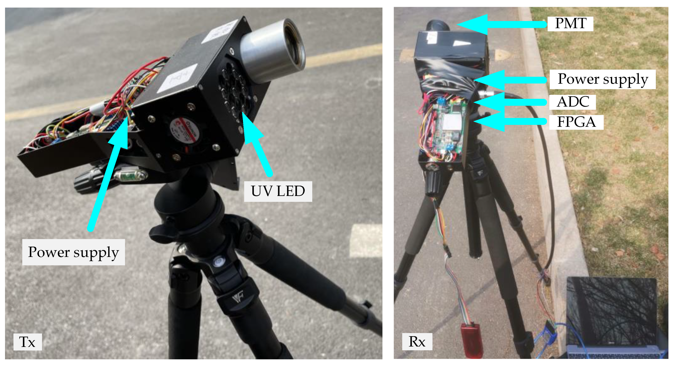
4.1. Experimental Conditions

We constructed an outdoor test system for NLOS UV communication to verify and clarify the isosceles model. As shown in Figure 4, the transmitter and receiver were placed on both sides of the straight road, and the transmission distance was selected as 100 m and 400 m, respectively. The outdoor test date and time were 15 March 2022, 2:00–5:00 p.m. in Beijing, with clear weather and assuming stable air. The multiple scattering and atmospheric turbulence were not concerns. The transmitter and receiver test bench are shown in Figure 5. On the transmitter side, we used 9 UV light-emitting diode (LED) array components as the light source. The beam angle was 20°, the center wavelength was 265 nm, and the module output power was 410 mW. To improve the utilization rate of signal light, we added a total internal reflection lens in front of the LED. On the receiver side, the H10720-09 module of Hamamatsu Company was used as the photomultiplier tube (PMT). The spectral response range was 160 nm to 320 nm, and the receiving aperture area was 2 cm2. In addition, the quantum efficiency was 20%. To reflect the path loss of the UV system and minimize the noise floor, we added a solar-blind 16% transmittance filter in front of the PMT with a peak transmission band between 258–275 nm, and the FOV was 20°. The weak current signal detected by the PMT was increased through the cross-group amplifier and then sampled by the analog-to-digital conversion (ADC). The XC7K325T core board of Xilinx was used as the processor for photon binarization and counting statistics.
The received energy of photon per unit time is defined as the receiver power, which is expressed as
P r = W t ,
where t is the time for photon counting, and W = N × E , where N represents the number of photons, and E is the energy of a single photon, where E = h × f . Finally, the total power at the receiving end can be expressed as
P r = N × h × c t × λ .
We have already known the transmit power P t , so the path loss of the NLOS UV link can be expressed as P L = 10 log P r / P t . The relevant parameters for outdoor testing are given in Table 1.

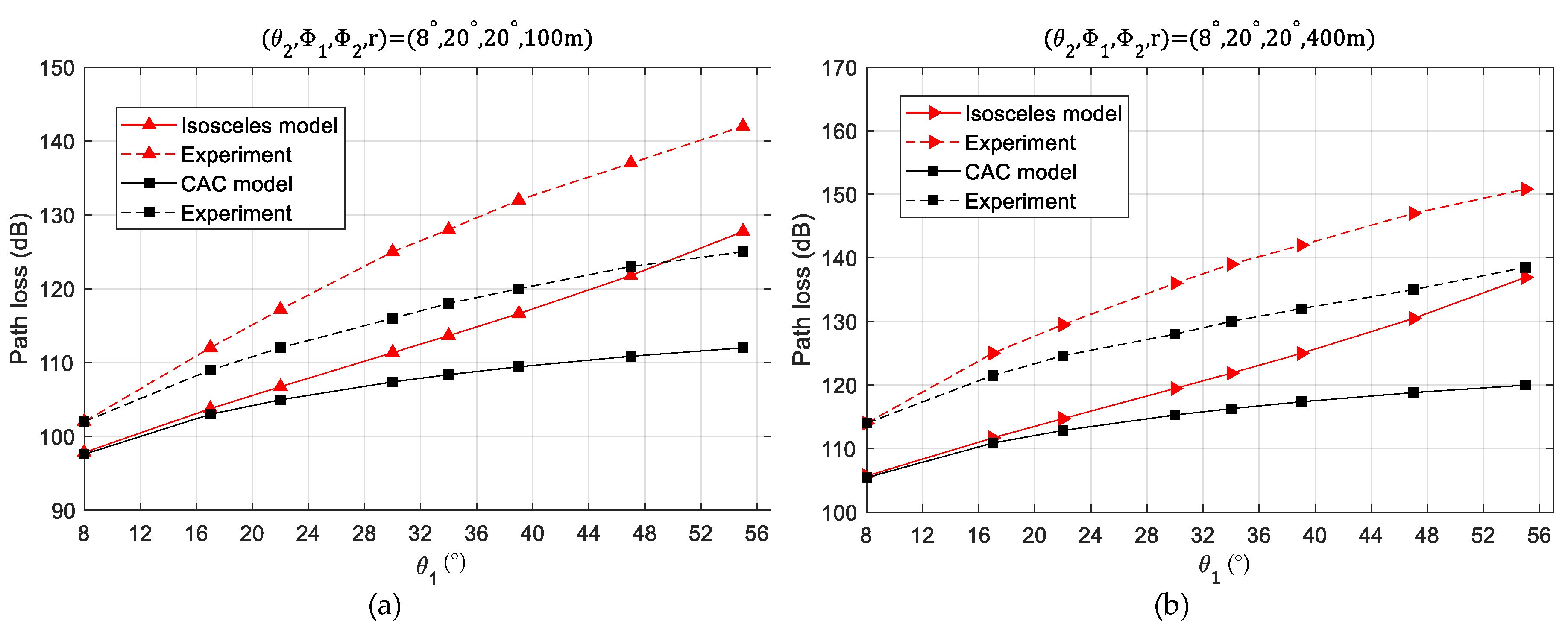
4.2. Experimental Results

The time was set to 500 ms to count received photons. Because the received power was calculated by counting the number of received photons, it was necessary to test the light background noise in the environment. The number of background light noises in the environment of 500 ms was about 300. We also set two scenarios with baseline distances of 100 m and 400 m, respectively. To prevent line-of-sight communication, we set the receiver angle to 8°. The isosceles model was approximated by increasing the same elevation angle of the transmitter and receiver at the same time; the “CAC” model was approximated by fixing the receiver elevation angle but increasing the transmitter elevation angle.
When r is set to 100 m or 400 m, the experimental and simulation results are shown in Figure 6, and the results show the same trend as the simulation result. When r = 100 m and the launching elevation   θ 1 is lower than 20°, which is shown in Figure 6a, the deviation between the isosceles model and the “CAC” model is less than 3 dB, which shows that the isosceles model can well approximate the “CAC” model when r = 400 m; the same conclusion is also obtained in Figure 6b. The above analysis shows that the application of the isosceles model is not sensitive to baseline distance. As for the deviations between the simulation results and the experimental results, the main reasons are, first, multiple scattering may occur when the density of particles in the air is relatively high; meanwhile, UV photons interact with abundant atmospheric molecules and aerosol particles. Both of these can lead to increasing path loss. Second, because it is difficult to strictly match LED and filter wavelengths, some photons are lost at the receiver, which makes reception less efficient. Finally, the transmitter integrates with nine LEDs, which makes the local temperature rise too fast and results in lower LED efficiency. These two factors lower the reception efficiency and thus increase the path loss.

5. Conclusions

In this paper, a practical approximate isosceles model in the case of small-angle coplanar single scattering is proposed, which is based on single scattering, but the complicated path solution process from the transceiver to the scattering region is avoided. In addition, the effects of different communication parameters on applicability are simulated, and the results demonstrate that the smaller the transceiver elevation angles are, the better the isosceles model performance is. Outdoor testing verified the applicability and accuracy of the isosceles model. The results show that when the receiving and transmitting angle is less than 20°, the model can well approximate the existing single scattering model. The effect of the baseline distance on the applicability of the isosceles model is not dominant.
For future work, in order to increase the communication distance, we will consider the theory related to the UV grouping network, which provides the basis for establishing a UV grouping network communication test platform.

Author Contributions

Conceptualization, A.D.; hardware, Y.W.; software, A.D.; validation, A.D., J.Z., N.S. and Y.Z.; writing—original draft preparation, A.D.; writing—review and editing, A.D. and Y.W.; project administration, J.L. All authors have read and agreed to the published version of the manuscript.

Funding

This research was funded by the National Key R&D Program of China under Grant 2019YFB2203700 and 2018YFB2200504, the National Nature Science Fund of China under Grants 61727815, 62105323, 61674142 and 62041502.

Institutional Review Board Statement

Not applicable.

Informed Consent Statement

Not applicable.

Data Availability Statement

Not applicable.

Conflicts of Interest

The authors declare no conflict of interest. The funders had no role in the design of the study; in the collection, analyses, or interpretation of data; in the writing of the manuscript, or in the decision to publish the results.

References

  1. Xu, Z.; Sadler, B.M. Ultraviolet Communications: Potential and State-Of-The-Art. IEEE Commun. Mag. 2008, 46, 67–73. [Google Scholar] [CrossRef]
  2. Vavoulas, A.; Sandalidis, H.G.; Chatzidiamantis, N.D.; Xu, Z.; Karagiannidis, G.K. A Survey on Ultraviolet C-Band (UV-C) Communications. IEEE Commun. Surv. Tutor. 2019, 21, 2111–2133. [Google Scholar] [CrossRef]
  3. Reilly, D.M.; Warde, C. Temporal characteristics of single-scatter radiation. J. Opt. Soc. Am. 1979, 69, 464–470. [Google Scholar] [CrossRef]
  4. Luettgen, M.R.; Shapiro, J.H.; Reilly, D.M. Non-line-of-sight single-scatter propagation model. J. Opt. Soc. Am. A 1991, 8, 1964–1972. [Google Scholar] [CrossRef]
  5. Elshimy, M.A.; Hranilovic, S. Non-line-of-sight single-scatter propagation model for noncoplanar geometries. J. Opt. Soc. Am. A 2011, 28, 420–428. [Google Scholar] [CrossRef]
  6. Wang, L.; Xu, Z.; Sadler, B.M. An approximate closed-form link loss model for non-line-of-sight ultraviolet communication in noncoplanar geometry. Opt. Lett. 2011, 36, 1224–1226. [Google Scholar] [CrossRef]
  7. Zuo, Y.; Xiao, H.; Wu, J.; Li, Y.; Lin, J. A single-scatter path loss model for non-line-of-sight ultraviolet channels. Opt. Express 2012, 20, 10359–10369. [Google Scholar] [CrossRef]
  8. Zuo, Y.; Xiao, H.; Wu, J.; Li, W.; Lin, J. Closed-form path loss model of non-line-of-sight ultraviolet single-scatter propagation. Opt. Lett. 2013, 38, 2116–2118. [Google Scholar] [CrossRef]
  9. Wang, L.; Xu, Z.; Sadler, B.M. Non-line-of-sight ultraviolet link loss in noncoplanar geometry. Opt. Lett. 2010, 35, 1263–1265. [Google Scholar] [CrossRef]
  10. Ding, H.; Chen, G.; Majumdar, A.; Sadler, B.; Xu, Z. Modeling of non-line-of-sight ultraviolet scattering channels for communication. IEEE J. Sel. Areas Commun. 2009, 27, 1535–1544. [Google Scholar] [CrossRef]
  11. Drost, R.J.; Moore, T.J.; Sadler, B.M. UV communications channel modeling incorporating multiple scattering interactions. J. Opt. Soc. Am. A 2011, 28, 686–695. [Google Scholar] [CrossRef] [PubMed]
  12. Yin, H.; Jia, H.; Zhang, H.; Wang, X.; Chang, S.; Yang, J. Vectorized polarization-sensitive model of non-line-of-sight multiple-scatter propagation. J. Opt. Soc. Am. A 2011, 28, 2082–2085. [Google Scholar] [CrossRef] [PubMed]
  13. Bos, J.P.; Hammel, S.; van Eijk, A.M.; Rodriguez, R.; Wang, A.; Chen, G.; Carrasco, R.; Marchan, S.C.; Reeves, A.D.; Torres, E.; et al. Modeling and experiment verification of non-line-of-sight ultraviolet overwater communication channel. In Proceedings of the Laser Communication and Propagation through the Atmosphere and Oceans VII, San Diego, CA, USA, 20–22 August 2018. [Google Scholar]
  14. Song, P.; Zhou, X.; Song, F.; Su, C.; Wang, A. Performance analysis of UV multiple-scatter communication system with height difference. Appl. Opt. 2017, 56, 8908–8916. [Google Scholar] [CrossRef] [PubMed]
  15. Hu, W.; Zhang, M.; Li, Z.; Popov, S.; Leeson, M.; Xu, T. High-Dimensional Feature Based Non-Coherent Detection for Multi-Intensity Modulated Ultraviolet Communications. J. Lightwave Technol. 2022, 40, 1879–1887. [Google Scholar] [CrossRef]
  16. Cao, T.; Gao, X.; Wu, T.; Pan, C.; Song, J. Reflection-Assisted Non-Line-of-Sight Ultraviolet Communications. J. Lightwave Technol. 2022, 40, 1953–1961. [Google Scholar] [CrossRef]
  17. Xu, C.; Zhang, H.; Cheng, J. Effects of haze particles and fog droplets on NLOS ultraviolet communication channels. Opt. Express 2015, 23, 23259–23269. [Google Scholar] [CrossRef]
  18. Aung, T.Y.; Arya, S.; Chung, Y.H. Performance dependence of non-line-of-sight ultraviolet communications on atmospheric parameters of the ultraviolet channel. Opt. Commun. 2019, 443, 7–11. [Google Scholar] [CrossRef]
  19. Xu, Z.; Ding, H.; Sadler, B.M.; Chen, G. Analytical performance study of solar blind non-line-of-sight ultraviolet short-range communication links. Opt. Lett. 2008, 33, 1860–1862. [Google Scholar] [CrossRef]
  20. van Eijk, A.M.J.; Gupta, A.; Noshad, M.; Brandt-Pearce, M.; Davis, C.C.; Hammel, S.M.; Majumdar, A.K. NLOS UV channel modeling using numerical integration and an approximate closed-form path loss model. In Proceedings of the Laser Communication and Propagation through the Atmosphere and Oceans, San Diego, CA, USA, 13–15 August 2012. [Google Scholar]
  21. Ke, X.Z. Theory of Ultraviolet Self-Organizing Network; Science Press: Beijing, China, 2011. [Google Scholar]
  22. Song, P.; Liu, C.; Zhao, T.; Guo, H.; Chen, J. Research on pulse response characteristics of wireless ultraviolet communication in mobile scene. Opt. Express 2019, 27, 10670–10683. [Google Scholar] [CrossRef]
  23. Ding, H.; Chen, G.; Xu, Z.; Sadler, B.M. Channel modelling and performance of non-line-of-sight ultraviolet scattering communications. IET Commun. 2012, 6, 514–524. [Google Scholar] [CrossRef]
  24. Chen, G.; Xu, Z.; Ding, H.; Sadler, B.M. Path loss modeling and performance trade-off study for short-range non-line-of-sight ultraviolet communications. Opt. Express 2009, 17, 3929–3940. [Google Scholar] [CrossRef] [PubMed]
  25. Li, B.; Wang, H.; Liu, M.; Hu, H.; Mao, Z. Applicability of non-line-of-sight ultraviolet single-scatter approximation model. Photonic Netw. Commun. 2015, 31, 147–154. [Google Scholar] [CrossRef]
  26. Zachor, A.S. Aureole radiance field about a source in a scattering–absorbing medium. Appl. Opt. 1978, 17, 1911–1922. [Google Scholar] [CrossRef] [PubMed]
  27. Bucholtz, A. Rayleigh-scattering calculations for the terrestrial atmosphere. Appl. Opt. 1995, 34, 2765–2773. [Google Scholar] [CrossRef]
Figure 1. NLOS single scattering communication geometry.
Photonics 09 00363 g001
Figure 2. The relationship between path loss and elevation angle, FOV angle, beam angle, and distance: ( a )   ( θ 1 ,   θ 2 ,   ϕ 1 ,   ϕ 2 = 10 ° ,   10 ° ,   20 ° ,   20 ° ) , ( b )   ( θ 1 ,   θ 2 ,   ϕ 1   , ϕ 2 = 15 ° ,   10 ° ,   20 ° ,   20 ° ) , ( c )   ( θ 1 ,   θ 2 ,   ϕ 1 ,   ϕ 2 = 40 ° ,   10 ° ,   20 ° ,   20 ° ) , ( d )   ( θ 1 ,   θ 2 ,   ϕ 1 ,   ϕ 2 = 60 ° ,   10 ° ,   20 ° ,   20 ° ) , ( e )   ( θ 1 ,   θ 2 ,   ϕ 1 ,   ϕ 2 = 15 ° ,   10 ° ,   60 ° ,   20 ° ) , ( f )   ( θ 1 ,   θ 2 ,   ϕ 1 ,   ϕ 2 = 15 ° ,   10 ° ,   60 ° ,   30 ° ) .
Photonics 09 00363 g002aPhotonics 09 00363 g002b
Figure 3. Relationship between path loss and transmit elevation angle.
Photonics 09 00363 g003
Figure 4. The location of the receiver and transmitter.
Photonics 09 00363 g004
Figure 5. Outdoor NLOS UV communication test platform.
Photonics 09 00363 g005
Figure 6. Simulation and experiment of the relationship between different launch angles and path loss at r = 100 m and r = 400 m: (a) ( θ 2 ,   ϕ 1 ,   ϕ 2 ,   r = 8 ° ,   20 ° ,   20 ° ,   100   m ) , (b) (   θ 2 ,   ϕ 1 ,   ϕ 2 ,   r = 8 ° ,   20 ° ,   20 ° ,   400   m ) .
Photonics 09 00363 g006
Table 1. Selection of key parameters of the UV system.
SymbolPhysical ExplanationValue
h Planck’s constant 6.62 × 10 34 J ·s
c speed of light 3.0 × 10 8 m/s
λ wavelength265 nm
P t transmitted power400 mW
A r receiving area2 cm2
ϕ 1 Tx full beam angle 15 °
ϕ 2 Rx field of view 20 °
α T Off-axis angle of the transmitter 0 °
α R The off-axis angle of the receiver 0 °
rCommunication distance100 m and 400 m
Publisher’s Note: MDPI stays neutral with regard to jurisdictional claims in published maps and institutional affiliations.

