Article

MOF Derived Manganese Oxides Nanospheres Embedded in N-Doped Carbon for Oxygen Reduction Reaction

Shenzhen Key Laboratory of Polymer Science and Technology, Guangdong Research Center for Interfacial Engineering of Functional Materials, College of Materials Science and Engineering, Shenzhen University, Shenzhen 518060, China
*
Authors to whom correspondence should be addressed.
Submission received: 4 July 2022 / Revised: 23 August 2022 / Accepted: 26 August 2022 / Published: 28 August 2022
(This article belongs to the Special Issue Inorganic Materials for Fuel Cell Electrocatalysts)

Abstract

:
Manganese oxides (MnOx) have been regarded as promising catalyst candidates for oxygen reduction reaction (ORR) due to their natural abundance and extremely low toxicity. However, the intrinsic low conductivity of MnOx limits their application. In this work, Mn oxide embedded in N doped porous carbon (MnOx@C-N) electrocatalysts were prepared through a facile zeolitic imidazolate framework (ZIF-8) template method for ORR. The structure, morphology, and composition of the prepared materials were characterized by X-ray diffraction (XRD), scanning electron microscopy (SEM), and X-ray photoelectron spectroscopy (XPS). Electrocatalytic performances of the prepared materials were investigated by linear sweep voltammetry. Benefiting from the well-defined morphology, high surface area, and porous structure, the MnOx@C-N electrocatalyst showed the highest ORR activity among all investigated materials with the limiting current density of 5.38 mA/cm2 at a rotation speed of 1600 rpm, the positive half-wave potential of 0.645 V vs. RHE, and the electron transfer number of 3.90. This work showcases an effective strategy to enhance ORR activity of MnOx.

1. Introduction

The electrocatalytic oxygen reduction is one of the key limiting factors for the performance of proton exchange membrane fuel cells due to its sluggish kinetics [1,2,3,4,5,6]. Thus, the exploration of the efficient oxygen reduction reaction (ORR) electrocatalysts is of great significance. Nowadays, Pt-based materials are known as the best ORR electrocatalysts. However, the high prices and the scarcity of platinum require exploration or the development of low-cost non-precious electrocatalysts. As an alternative non-noble metal catalyst for ORR, MnO2 has been extensively used for applications in catalysis and electrochemical energy storage [7,8,9,10,11,12,13,14,15]. However, MnO2 has intrinsic low electrical conductivity and suffers from dissolution and agglomeration issues. These limit its ORR catalytic activity. To overcome the above-mentioned drawbacks, coupling MnO2 with highly conductive carbon-based materials (carbon black, carbon nanotubes, graphene, activated carbons) has been widely reported [15,16,17,18].
Zeolitic imidazolate frameworks (ZIFs), which are an extensive class of crystalline materials with three-dimensional structure (3D), a diverse array of metals and organic linkers, and permanent porosity [19,20], have been utilized as templates and precursors to fabricate porous carbon-based functional materials using direct heat treatment in an inert atmosphere and subsequent acid leaching process. [21,22] A subclass of ZIFs, ZIF-8 nanocrystals, composed of imidazolate linkers containing Zn2+ ions, carbon and nitrogen atoms, have been identified as a promising precursor for the preparation of metal doped nanoporous carbon electrocatalysts with high graphitization and a hierarchical porous structure, achieving high mass transfer rate owing to the large pore volume and large surface area. [23] ZIF-8-derived nanocarbon materials doped with transition metal oxides via the impregnation method can further enhance their catalytic activity and electronic conductivity. Particularly, Mn oxides-N-C catalysts containing active C-N and Mn-N moieties on the surface have received great attention recently due to their excellent ORR activity in both acidic and alkaline solutions [24,25].
Herein, we report a simple and effective approach for preparing well-defined, high-performance, ZIF-8 derived MnOx@C-N nanospheres by introducing Mn oxides during ZIF-8 synthesis. To the best of our knowledge, electrocatalysts based on gamma-MnO2 (γ-MnO2) supported on N-doped carbon have not yet been investigated for ORR.

2. Results and Discussion

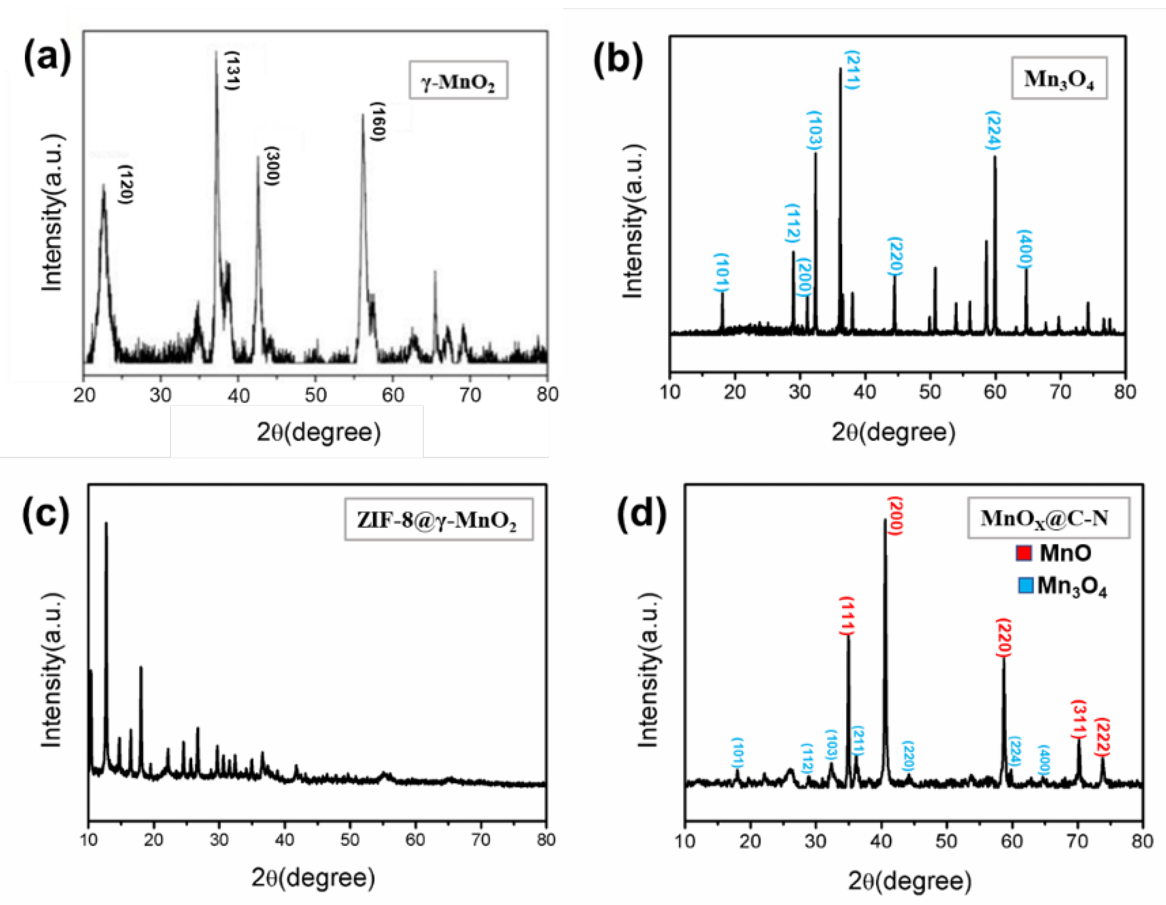
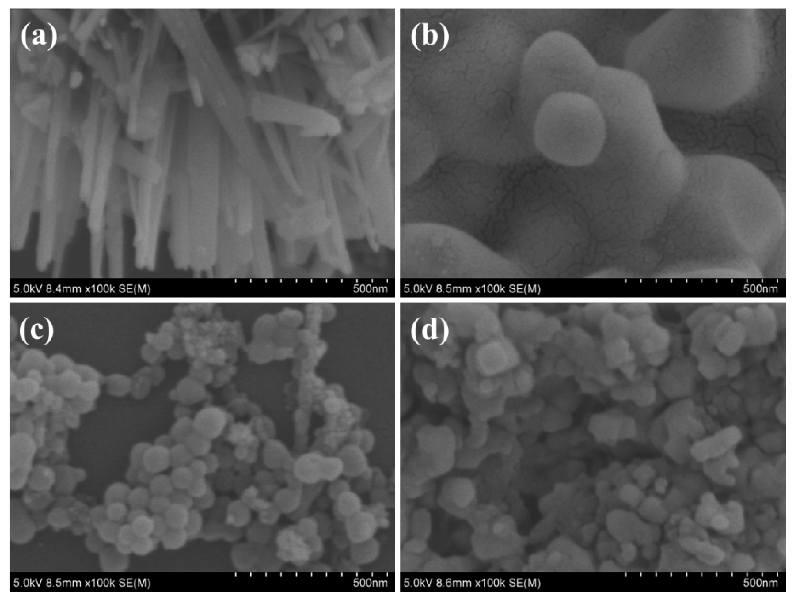
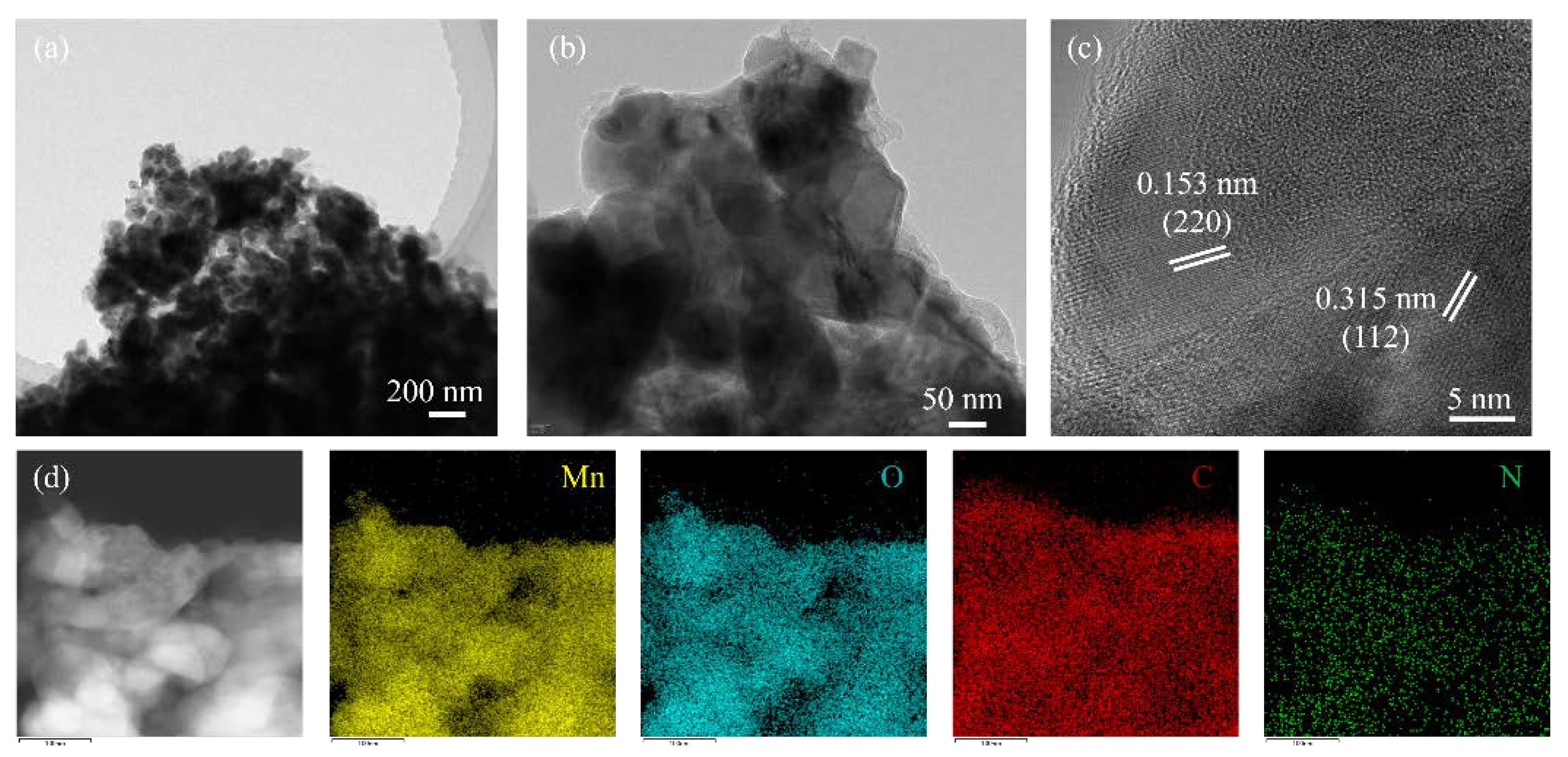
2.1. Materials Characterization

MnOx@C-N was synthesized following the procedure shown in Figure 1. Firstly, γ-MnO2 was prepared by a hydrothermal method. Then ZIF-8@γ-MnO2 hybrid was obtained through the assembly of Zn2+ ions with 2-methylimidazole in the presence of γ-MnO2. After that, ZIF-8@γ-MnO2 was pyrolyzed in Ar atmosphere to obtain MnOx@C-N.
The XRD patterns of four kinds of particles are shown in Figure 2. Figure 2a shows the four diffraction peaks at (2θ) 22.43°, 37.12°, 42.61°, 56.14° in the as-prepared γ-MnO2 sample are consistent with the pure orthorhombic phase of γ-MnO2 (JCPDS No. 14-0644). The all-diffraction peaks like (2θ) 32.38°,36.08°, and 59.91° of the γ-MnO2 heated under 800 °C (Figure 2b) can be indexed to the tetragonal phase of Mn3O4 (JCPDS No. 24-0734). This indicates that γ-MnO2 completely changes into Mn3O4 after high-temperature treatment. The XRD pattern of ZIF-8@γ-MnO2 and MnOx@C-N are shown in Figure 2c and Figure 2d, respectively. After the pyrolysis step, the Mn oxides in MnOx@C-N are a mixture of MnO (JCPDS No. 78-0424) and Mn3O4. Although ZIF-8 contains C and Zn, the Zn atoms (MP 420 °C, BP 907 °C) evaporate at a high temperature of 800 °C [26], and the weight percentage of the MnOx sample is only 0.0152% when tested by ICP. Furthermore, carbon does not crystallize well. Therefore, the XRD pattern does not show peaks for the two elements.
The γ-MnO2 displays a nano-rod morphology with a diameter of ~74 nm as shown in Figure 3a. Figure 3b shows the SEM image of γ-MnO2 heated under 800 °C. The diameter of nano-rods heat-treated MnO2 is larger than that of pristine γ-MnO2. From Figure 3c, it can be seen that the length of polyhedral ZIF-8@γ-MnO2 particles is about 2 µm on average. After pyrolysis, the average size of MnOx@C-N particles is about 500 nm (Figure 3d), which is smaller than that of the ZIF-8@γ-MnO2.
To gain more structure information of MnOx@C-N, transmission electron microscopy (TEM) was performed. From Figure 4c, it is seen that there are two different domains, which indicate a cubic phase and a tetragonal phase. The measured lattice fringe value of MnOx@C-N is about 0.157 nm and 0.309 nm, matching the (220) lattice spacing of MnO and the (112) lattice spacing of Mn3O4, respectively. This is consistent with the XRD result. High-angle annular dark-field scanning TEM (HADDF-TEM) and the energy-dispersive X-ray (EDX) element mappings (Figure 4d) show that Mn, O, C, N elements are uniformly distributed in the sample.
To quantitatively evaluate the degree of aggregation and fusion, the surface area and pore structures of pristine γ-MnO2, ZIF-8@γ-MnO2 and MnOx@C-N were characterized by N2 adsorption/desorption measurements (Figure 5). The pristine γ-MnO2 exhibited type-II isotherms, suggesting that pristine γ-MnO2 is non-porous. By contrast, MnOx@C-N shows typical type-IV isotherms with sharp uptakes at relatively low N2 partial pressures and well-defined hysteresis loops at higher N2 pressure (from 0.5 to 1.0). This indicates that the coexistence of both micropores and mesopores. γ-MnO2 exhibits very low surface area (46 m2/g) and pore volume (0.0244 cm3/g) as compared to ZIF-8@γ-MnO2 and MnOx@C-N. The surface area and pore volume of ZIF-8@γ-MnO2 were 1132.3 m2/g and 0.7481 cm3/g, respectively, the highest values among these three different electrocatalysts (Table 1). The surface area and pore volume for MnOx@C-N declined by 79.7 and 12.4% compared with ZIF-8@γ-MnO2. MnOx@C-N has a larger specific surface area and porosity as compared with γ-MnO2. The relatively high specific surface area and large mesopores would make the catalyst expose more active sites, promote gas diffusion, and mass transfer, and improve ORR performance.
XPS measurements are carried out to investigate the influence of the heat treatment process. The N 1s XPS spectra of MnOx@C-N are presented in Figure 6b. It can be deconvoluted to four peaks: oxidized N (402.3 ± 0.3 eV), graphitic N (400.8 ± 0.1 eV), pyridinic N (398.4 ± 0.1 eV), and pyrrolic N (399.8 ± 0.1 eV) [26,27,28,29,30]. The contents of Mn, O, and C on the surface of MnOx@C-N are 1.39%, 5.73%, and 89.51%, respectively. The surface N content in MnOx@C-N was measured to be 3.37%, and the relative surface nitrogen amounts of oxidized N, graphitic N, pyridinic N, pyrrolic N are 10.4%, 31.9%, 32.8%, and 24.9%, respectively. The weight percentage of C and N is determined to be 39.58% and 3.37% by element analysis. Pyridinic N has the highest content over the other three types of N in MnOx@C-N. Pyridinic-N can provide one p-electron to the aromatic π-systems, which could improve the electron-donor property of the catalyst and enhance its electrochemical performance [25].

2.2. Electrochemical Results

ZIF-8 was also prepared for comparison (Figures S1 and S2). Figure 7 shows linear sweeping voltammograms of the ORR on four different kinds of electrocatalysts. For four kinds of different electrocatalysts, the voltametric profiles show that the current densities enhance with the increase in the rotation rate from 400 to 2000 rpm. The contribution from GCE can be ignored due to its negligible current response (Figure S3). From Figure 7, it is seen that the cathodic current density in Ar saturated solution is negligible compared with the cathodic current density in O2-saturated solution. Therefore, the disk currents in the O2-saturated solution can represent the ORR activity of the samples. Figure 8a shows the corresponding Koutecky–Levich (K-L) plots and fitting lines of the samples obtained from rotation-speed dependent current. Based on the slopes of K-L curves, the electron transfer number (n) of the pristine γ-MnO2, ZIF-8@γ-MnO2, and MnOx@C-N samples are evaluated to be 3.35, 3,55, and 3.90 at 0.45 V, respectively. This indicates that the electron transfer number of the MnOx@C-N sample is the highest among these three samples, and the number of electron transfers is close to that reported in published articles. [31] In Figure 8b, the half-wave potential of MnOx@C-N is 63 and 130 mV more positive than that of ZIF-8@γ-MnO2 and γ-MnO2. The enhanced ORR performance of MnOx@C-N can be originated from its large pore volume and superior ionic conductivity. Figure 8c shows LSV curves for these three electrocatalysts at 1200 rpm. Clearly, the ORR current density of MnOx@C-N under the same voltage is the largest among three different electrocatalysts between 0.35 and 0.8 V and the onset potential of MnOx@C-N is the highest among three electrocatalysts.

3. Materials and Methods

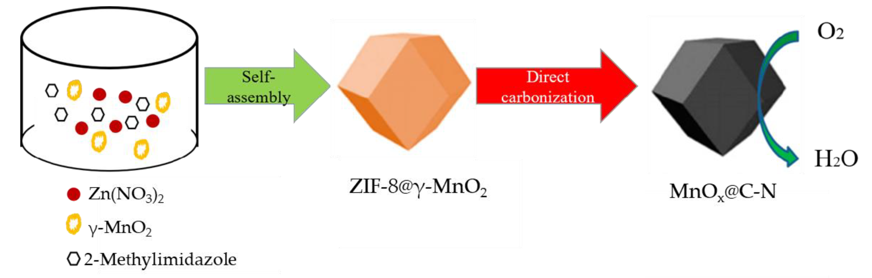
3.1. Synthesis of γ-MnO2 Nanorods

The γ-MnO2 particles were prepared by a facile hydrothermal method [10]. In the procedure, 4.575 g (NH4)2S2O8 and 3.375 g MnSO4·H2O were firstly dissolved into 80 mL of deionized water under magnetic stirring until it was completely dissolved, and then the solution was moved into a 100 mL Teflon autoclave, sealed and maintained at 90 °C for 24 h in an oven. After cooling to room temperature, the product was collected by centrifugation and then washed with deionized water and absolute ethanol several times, followed by drying at 60 °C for 10 h.

3.2. Synthesis of Porous MnOx@C-N Nanospheres

In a typical synthesis, the as-obtained γ-MnO2 nanorods were dispersed into 30 mL of absolute methanol and mixed with 0.3752 g polyvinylpyrrolidone, 0.6568 g 2-methylimidazole, and 0.2974 g Zn(NO3).6H2O. Afterward, the resultant mixed solution was stirred for 2 h at room temperature and the brown precipitate was collected by centrifugation and then washed with deionized water and absolute methanol several times, followed by drying at 60 °C for 10 h. Finally, the MnOx@C-N nanospheres were obtained by annealing the ZIF-8@γ-MnO2 at 800 °C for 3 h in argon atmosphere with a heating rate of 5 °C min−1.

3.3. Physical Characterizations

The phase structure of the as-prepared samples was analyzed by X-ray diffraction (XRD, Bruker D8 Advance SS/18 Kw diffractometer, Germany) with Cu K Kα radiation. The morphological structures were observed by field emission scanning electron microscopy (SEM, JEOL JAMP-9500F, Japan). X-ray photoelectron spectroscopy (XPS, ES-CALAB 250Xi, Thermo Fisher Scientific, Waltham, MA, USA) was used for compositional analysis. The surface area measurements were made by N2 adsorption/desorption using a micromeritics ASAP 2020, USA.

3.4. Electrochemical Activity Testing

Electrocatalytic activity evaluations were conducted on a CHI660C electrochemical test system (Chen Hua, Shanghai, China). All the measurements were carried out in a three-electrode system using Ag/AgCl as reference electrode, graphite rod as a counter electrode, and glassy carbon rotating disk electrode (GCE) as a working electrode. For the preparation of the working electrode for ORR measurements, the catalyst powder and acetylene black (weight ratio of 3:7) were dispersed in a solution containing 950 μL of alcohol and 50 μL of Nafion solution with the help of ultrasonication to form catalyst ink. Then 10 μL of the catalyst ink was dropped on the GCE surface (0.196 cm2) to form a thin film electrode. The electrolyte was 0.1 mol L−1 KOH (pH = 13) solution saturated with an O2 flow rate of 60 mL/min. The scan rate for linear sweeping voltammogram measurements was 5 mV s−1. LSV test was performed in N2/O2 saturated 0.1 M KOH with Ag/AgCl as the reference electrode. The voltage range was 0.2 V~−0.8 V (vs. Ag/AgCl). All the potentials were converted to reversible hydrogen electrode (RHE) using E (V vs. RHE) = E (V vs. Ag/AgCl) + 0.196 + 0.0592 × 13.
The rotating disc electrode test was performed in a 0.1 M KOH solution saturated with O2. The number of electrons transferred in the oxygen reduction reaction was calculated by using the Koutecky–Levich (K-L) equation:
1 J = 1 J K + 1 J L = 1 J K + 1 B ω 1 / 2
B = 0.62nFC0D02/3ν−1/6
where J represents the current density, JK represents the kinetic current density, JL represents the diffusion limit current density, ω represents the electrode rotation rate, n represents the electron transfer number, F represents the Faraday constant (96,485 C mol−1), C0 said is in 0.1 M KOH solution saturated O2 volume concentration (1.2 × 10⁻⁶ mol cm−3), D0 is O2 diffusion coefficient of rope (1.9 × 10⁻⁵ cm2 s−1), ν represents the dynamics of electrolyte viscosity (0.01 cm2 s−1).

4. Conclusions

A MOF-derived N-doped carbon nanosphere catalyst was synthesized by adding MnO2 during the synthesis of ZIF-8, followed by pyrolysis in an Ar atmosphere. It is found that carbonized treatment almost did not affect total pore volumes of ZIF-8@γ-MnO2. Meanwhile, compared with the electron transfer number of three prepared samples, the electron transfer number of MnOx@C-N is evaluated to be the highest value (3.90) at 0.45 V and MnOx@C-N showed a positive half-wave potential (0.645 V vs. RHE) and largest current density between 0.35 V and 0.8 V. This work provides an effective route to mitigate the dilemma of poor conductivity of MnOx for ORR.

Supplementary Materials

The following supporting information can be downloaded at: https://0-www-mdpi-com.brum.beds.ac.uk/article/10.3390/inorganics10090126/s1. Figure S1: SEM of ZIF-8; Figure S2: XRD of ZIF; Figure S3: Linear sweeping voltammograms of ORR on the GCE without catalyst ink.

Author Contributions

Conceptualization, Z.Z. and G.H.; methodology, Z.Z. and G.H.; software, G.H.; validation, X.-Z.F.; S.-Q.L. and J.-L.L.; formal analysis, Z.Z. and G.H.; investigation, G.H. and Z.Z.; data curation, Z.Z. and G.H.; writing—original draft preparation, G.H.; writing—review and editing, F.S. and S.-Q.L.; visualization, G.H. and Z.Z.; supervision, X.-Z.F.; project administration, J.-L.L.; funding acquisition, X.-Z.F. and J.-L.L. All authors have read and agreed to the published version of the manuscript.

Funding

This research was funded by Shenzhen Science and Technology Program (KQTD20190929173914967 and JCYJ20200109110416441).

Data Availability Statement

Data is contained within the article.

Conflicts of Interest

The authors declare no conflict of interest.

References

  1. Steele, B.C.H.; Heinzel, A. Materials for fuel-cell technologies. Nature 2001, 414, 345–352. [Google Scholar] [CrossRef] [PubMed]
  2. Xiong, W.; Du, F.; Liu, Y.; Perez, J.A.; Supp, M.; Ramakrishnan, T.S.; Dai, L.; Jiang, L. 3-D Carbon Nanotube Structures Used as High Performance Catalyst for Oxygen Reduction Reaction. J. Am. Chem. Soc. 2010, 132, 15839–15841. [Google Scholar] [CrossRef] [PubMed]
  3. Zaman, S.; Huang, L.; Douka, A.I.; Yang, H.; You, B.; Xia, B.Y. Oxygen Reduction Electrocatalysts toward Practical Fuel Cells: Progress and Perspectives. Angew. Chem. 2021, 133, 17976–17996. [Google Scholar] [CrossRef]
  4. Zhang, T.; Wu, J.; Wang, Z.; Wei, Z.; Liu, J.; Gong, X. Transfer of molecular oxygen and electrons improved by the regulation of C-N/C=O for highly efficient 2e-ORR. Chem. Eng. J. 2022, 433, 133591. [Google Scholar] [CrossRef]
  5. He, J.; Zheng, T.; Wu, D.; Zhang, S.; Gu, M.; He, Q. Insights into the Determining Effect of Carbon Support Properties on Anchoring Active Sites in Fe–N–C Catalysts toward the Oxygen Reduction Reaction. ACS Catal. 2022, 12, 1601–1613. [Google Scholar] [CrossRef]
  6. Yang, N.; Peng, L.; Li, L.; Li, J.; Liao, Q.; Shao, M.; Wei, Z. Theoretically probing the possible degradation mechanisms of an FeNC catalyst during the oxygen reduction reaction. Chem. Sci. 2021, 12, 12476–12484. [Google Scholar] [CrossRef]
  7. Gu, T.; Agyeman, D.A.; Shin, S.; Jin, X.; Lee, J.M.; Kim, H.; Kang, Y.; Hwang, S. α-MnO2 Nanowire-Anchored Highly Oxidized Cluster as a Catalyst for LiO2 Batteries: Superior Electrocatalytic Activity and High Functionality. Angew. Chem. Int. Ed. 2018, 57, 15984–15989. [Google Scholar] [CrossRef]
  8. Ran, B.; Liu, G.; Cheng, Z.; Wang, X.; Qiao, S.Z. 3D Hollow α-MnO2 Framework as an Efficient Electrocatalyst for Lithium–Oxygen Batteries. Small 2019, 15, 1804958. [Google Scholar]
  9. Zhang, S.; Su, W.; Wei, Y.; Liu, J.; Li, K. Mesoporous MnO2 structured by ultrathin nanosheet as electrocatalyst for oxygen reduction reaction in air-cathode microbial fuel cell. J. Power Sources 2018, 401, 158–164. [Google Scholar] [CrossRef]
  10. Wang, C.; Zeng, Y.; Xiao, X.; Wu, S.; Zhong, G.; Xu, K.; Wei, Z.; Su, W.; Lu, X. γ-MnO2 nanorods/graphene composite as efficient cathode for advanced rechargeable aqueous zinc-ion battery. J. Energy Chem. 2020, 43, 182–187. [Google Scholar] [CrossRef]
  11. Zheng, H.; Modibedi, M.; Mathe, M.; Ozoemena, K. The thermal effect on the catalytic activity of MnO2 (α, β, and γ) for oxygen reduction reaction. Mater. Today Proc. 2017, 4, 11624–11629. [Google Scholar] [CrossRef]
  12. Fu, Y.; Gao, X.; Zha, D.; Zhu, J.; Ouyang, X.; Wang, X. Yolk–shell-structured MnO2 microspheres with oxygen vacancies for high-performance supercapacitors. J. Mater. Chem. A 2018, 6, 1601–1611. [Google Scholar] [CrossRef]
  13. Gu, Y.; Min, Y.; Li, L.; Lian, Y.; Sun, H.; Wang, D.; Rummeli, M.H.; Guo, J.; Zhong, J.; Xu, L.; et al. Crystal Splintering of β-MnO2 Induced by Interstitial Ru Doping Toward Reversible Oxygen Conversion. Chem. Mater. 2021, 33, 4135–4145. [Google Scholar] [CrossRef]
  14. Yin, M.; Miao, H.; Hu, R.; Sun, Z.; Li, H. Manganese dioxides for oxygen electrocatalysis in energy conversion and storage systems over full pH range. J. Power Sources 2021, 494, 229779. [Google Scholar] [CrossRef]
  15. Huang, Z.; Li, G.; Huang, Y.; Gu, X.; Wang, N.; Liu, J.; Li, O.L.; Shao, H.; Yang, Y.; Shi, Z. Facile one-pot synthesis of low cost MnO2 nanosheet/Super P Li composites with high oxygen reduction reaction activity for Zn-air batteries. J. Power Sources 2020, 448, 227385. [Google Scholar] [CrossRef]
  16. Ha, T.A.; Tran, V.M.; Le, M.L.P. Nanostructured composite electrode based on manganese dioxide and carbon vulcan–carbon nanotubes for an electrochemical supercapacitor. Adv. Nat. Sci. Nanosci. Nanotechnol. 2013, 4, 035004. [Google Scholar] [CrossRef]
  17. Awan, Z.; Nahm, K.S.; Xavier, J.S. Nanotubular MnO2/graphene oxide composites for the application of open air-breathing cathode microbial fuel cells. Biosens. Bioelectron. 2014, 53, 528–534. [Google Scholar]
  18. Xiong, C.; Yang, Q.; Dang, W.; Li, M.; Li, B.; Su, J.; Liu, Y.; Zhao, W.; Duan, C.; Dai, L.; et al. Fabrication of eco-friendly carbon microtubes @ nitrogen-doped reduced graphene oxide hybrid as an excellent carbonaceous scaffold to load MnO2 nanowall (PANI nanorod) as bifunctional material for high-performance supercapacitor and oxygen reduction reaction catalyst. J. Power Sources 2020, 447, 227387. [Google Scholar]
  19. Park, K.S.; Ni, Z.; Côté, A.P.; Choi, J.Y.; Huang, R.; Uribe-Romo, F.J.; Chae, H.K.; O’Keeffe, M.; Yaghi, O.M. Exceptional chemical and thermal stability of zeolitic imidazolate frameworks. Proc. Natl. Acad. Sci. USA 2006, 103, 10186–10191. [Google Scholar] [CrossRef]
  20. Banerjee, R.; Phan, A.; Wang, B.; Knobler, C.; Furukawa, H.; O’Keeffe, M.; Yaghi, O.M. High-Throughput Synthesis of Zeolitic Imidazolate Frameworks and Application to CO2 Capture. Science 2008, 319, 939–943. [Google Scholar] [CrossRef]
  21. Aijaz, A.; Masa, J.; Rösler, C.; Xia, W.; Weide, P.; Botz, A.J.; Fischer, R.A.; Schuhmann, W.; Muhler, M. Co@Co3O4 Encapsulated in Carbon Nanotube-Grafted Nitrogen-Doped Carbon Polyhedra as an Advanced Bifunctional Oxygen Electrode. Angew. Chem. Int. Ed. 2016, 55, 4087–4091. [Google Scholar] [CrossRef]
  22. Zhang, H.; Hwang, S.; Wang, M.; Feng, Z.; Karakalos, S.; Luo, L.; Qiao, Z.; Xie, X.; Wang, C.; Su, D.; et al. Single Atomic Iron Catalysts for Oxygen Reduction in Acidic Media: Particle Size Control and Thermal Activation. J. Am. Chem. Soc. 2017, 139, 14143. [Google Scholar] [CrossRef] [PubMed]
  23. Fu, X.; Gao, R.; Jiang, G.; Li, M.; Li, S.; Luo, D.; Hu, Y.; Yuan, Q.; Huang, W.; Zhu, N.; et al. Evolution of atomic-scale dispersion of FeNx in hierarchically porous 3D air electrode to boost the interfacial electrocatalysis of oxygen reduction in PEMFC. Nano Energy 2021, 83, 105734. [Google Scholar] [CrossRef]
  24. Salahuddin, U.; Iqbal, N.; Noor, T.; Hanif, S.; Ejaz, H.; Zaman, N.; Ahmed, S. ZIF-67 Derived MnO2 Doped Electrocatalyst for Oxygen Reduction Reaction. Catalysts 2021, 11, 92. [Google Scholar] [CrossRef]
  25. Li, F.; Qin, T.; Sun, Y.; Jiang, R.; Yuan, J.; Liu, X.; O’Mullane, A.P. Preparation of a one-dimensional hierarchical MnO@CNT@Co-N/C ternary nanostructure as a high-performance bifunctional electrocatalyst for rechargeable Zn-air batteries. J. Mater. Chem. A 2021, 9, 22533–22543. [Google Scholar] [CrossRef]
  26. Yin, P.; Yao, T.; Wu, Y.; Zheng, L.; Lin, Y.; Liu, W.; Ju, H.; Zhu, J.; Hong, X.; Deng, Z.; et al. Single Cobalt Atoms with Precise N-Coordination as Superior Oxygen Reduction Reaction Catalysts. Angew. Chem. 2016, 128, 10958–10963. [Google Scholar] [CrossRef]
  27. Chen, Y.Z.; Wang, C.; Wu, Z.Y.; Xiong, Y.; Xu, Q.; Yu, S.H.; Jiang, H.L. From Bimetallic Metal-Organic Framework to Porous Carbon: High Surface Area and Multicomponent Active Dopants for Excellent Electrocatalysis. Adv. Mater. 2015, 27, 5010–5016. [Google Scholar] [CrossRef]
  28. Hou, C.; Zou, L.; Xu, Q. A Hydrangea-Like Superstructure of Open Carbon Cages with Hierarchical Porosity and Highly Active Metal Sites. Adv. Mater. 2019, 31, 1904689. [Google Scholar] [CrossRef]
  29. Jiang, H.; Liu, Y.; Li, W.; Li, J. Co Nanoparticles Confined in 3D Nitrogen-Doped Porous Carbon Foams as Bifunctional Electrocatalysts for Long-Life Rechargeable Zn–Air Batteries. Small 2018, 14, 1703739. [Google Scholar] [CrossRef]
  30. Jiang, H.; Wang, Y.; Hao, J.; Liu, Y.; Li, W.; Li, J. N and P co-functionalized three-dimensional porous carbon networks as efficient metal-free electrocatalysts for oxygen reduction reaction. Carbon 2017, 122, 64–73. [Google Scholar] [CrossRef]
  31. Wang, H.; Yin, F.; Chen, B.; Li, G. Synthesis of an ε-MnO2/metal–organic-framework composite and its electrocatalysis towards oxygen reduction reaction in an alkaline electrolyte. J. Mater. Chem. A 2015, 3, 16168–16176. [Google Scholar] [CrossRef]
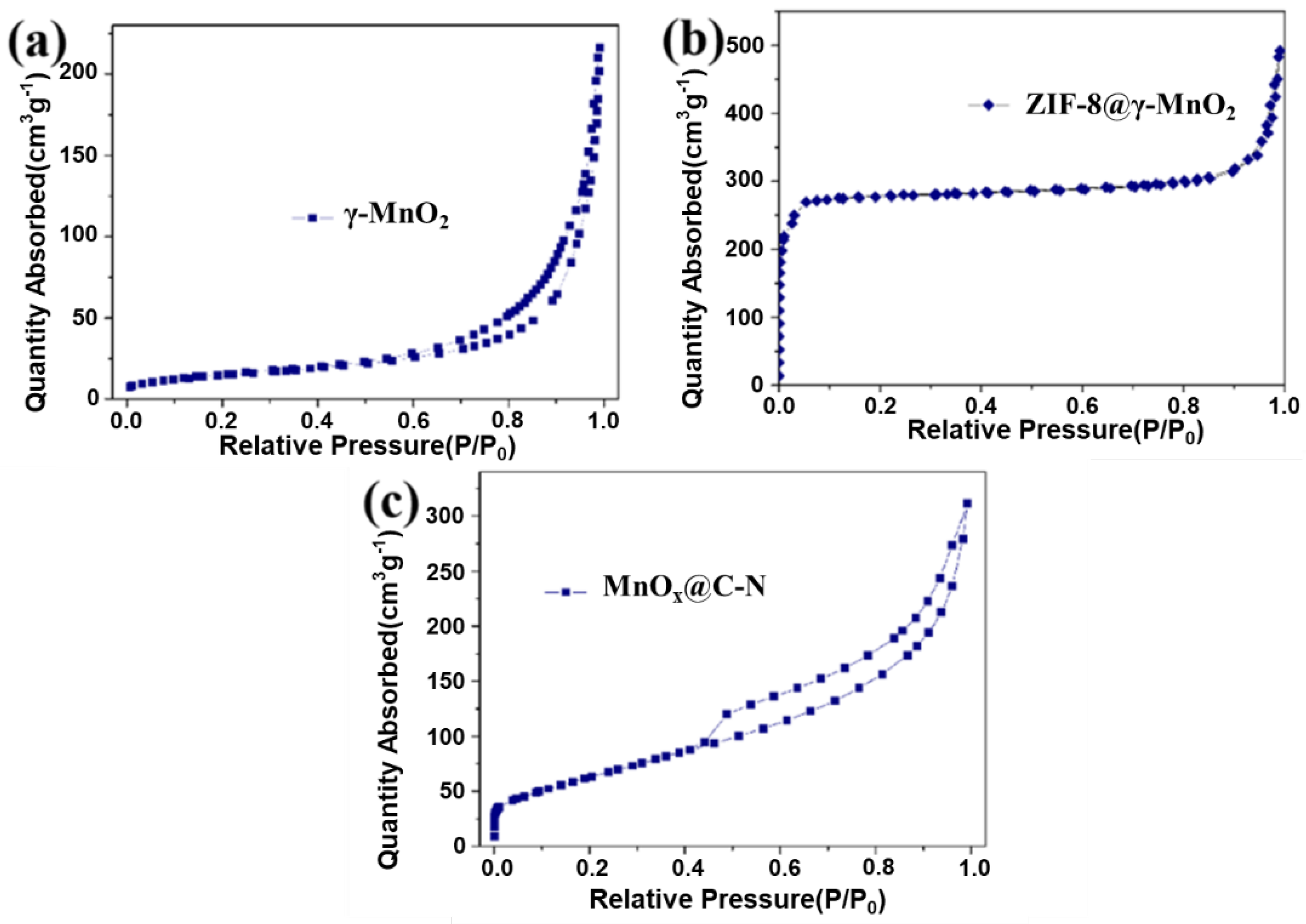
Figure 1. A schematic diagram showing the synthesis of MnOx@C-N.
Inorganics 10 00126 g001
Figure 2. XRD patterns of (a) γ-MnO2; (b) γ-MnO2 heated under 800 °C; (c) ZIF-8@γ-MnO2; and (d) MnOx@C-N.
Inorganics 10 00126 g002
Figure 3. SEM of (a) γ-MnO2; (b) γ-MnO2 heated under 800 °C; (c) ZIF-8@γ-MnO2; and (d) MnOx@C-N.
Inorganics 10 00126 g003
Figure 4. (a,b) TEM images of the MnOx@C-N samples. (c) HRTEM image of MnOx@C-N. (d) STEM image and corresponding element mapping (scale bar: 100 nm).
Inorganics 10 00126 g004
Figure 5. N2 physisorption isotherms for the catalyst. (a) γ-MnO2; (b) ZIF-8@γ-MnO2; and (c) MnOx@C-N.
Inorganics 10 00126 g005
Figure 6. (a) XPS of MnOx@C-N; (b) N1s XPS spectra of MnOx@C-N.
Inorganics 10 00126 g006
Figure 7. Linear sweeping voltammograms of ORR on (a) ZIF-8; (b) pristine γ-MnO2; (c) ZIF-8@γ-MnO2; and (d) MnOx@C-N at different rotating rates.
Inorganics 10 00126 g007
Figure 8. (a) K–L plot at 0.45 V; (b) Specific activities of the samples near the half-wave potential region at a rotation speed of 1200 rpm; and (c) LSV curves of γ-MnO2, ZIF-8@γ-MnO2, and MnOx@C-N at 1200 rpm.
Inorganics 10 00126 g008
Table 1. BET and total pore volume of different materials.
Materialsγ-MnO2ZIF-8@γ-MnO2MnOx@C-N
BET(m2/g)461132229
Total pore volume(cm3/g)0.02440.74810.6565
Publisher’s Note: MDPI stays neutral with regard to jurisdictional claims in published maps and institutional affiliations.

