2.1.1. Control of Macroporosity
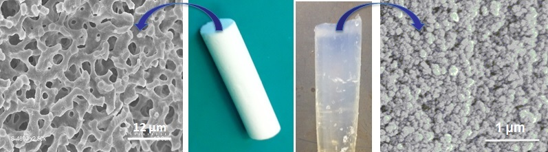
Silica monoliths of 6 mm diameter and 10 cm length exhibiting a hierarchical network of macro- and mesopores have been synthesized by chemical spinodal decomposition using polyethylene oxides (PEO) of 10 to 100 kDa in acidic (HNO
3) aqueous medium in the presence of tetraethylorthosilicate as silica source. The mathematical theory of spinodal decomposition is based largely on the development of a generalized diffusion equation [
13,
14]. The mechanism of spinodal decomposition can be visualized via an animation [
15], illustrating the microstructural evolution under the Cahn–Hilliard equation, showing distinctive coarsening and phase separation (
Figure 1). The phase separation ends at the sol-gel transition. The macropore size will be determined by the sol-gel transition kinetics and controlled by the size of the polymer, the ratio of EO unit/Si and the amount of acid. For a constant composition of the mixture (1 Si:14.21 H
2O:0.60 EO unit:0.26 HNO
3) increasing the size of the polymer increases the size of the macropore and in the same time of the skeleton thickness. For PEO of 20, 35, and 100 kDa, macropore sizes of 4, 10, and 16 microns and skeleton thickness of 3, 6, and 7 microns have been obtained, respectively [
9]. Lower molecular weight PEO polymers interact more strongly with silica oligomers via multiple interactions, they adsorb at the surface of the silica oligomer and cover the particle, leading to a faster condensation of the silica oligomers and favor the sol-gel transition, resulting in smaller pores. Higher molecular weight PEO polymers form loops on the silica surface, leading to an increase of the thickness of the adsorbed layer [
16] inducing a slower rate of condensation of silica oligomers and therefore slow down the sol-gel transition. For a given size of polymer as PEO 20 kDa, increasing the amount of polymer decreases the size of the macropores. For a composition mixture 1 Si:14.21 H
2O:
x EO unit:0.26 HNO
3 with
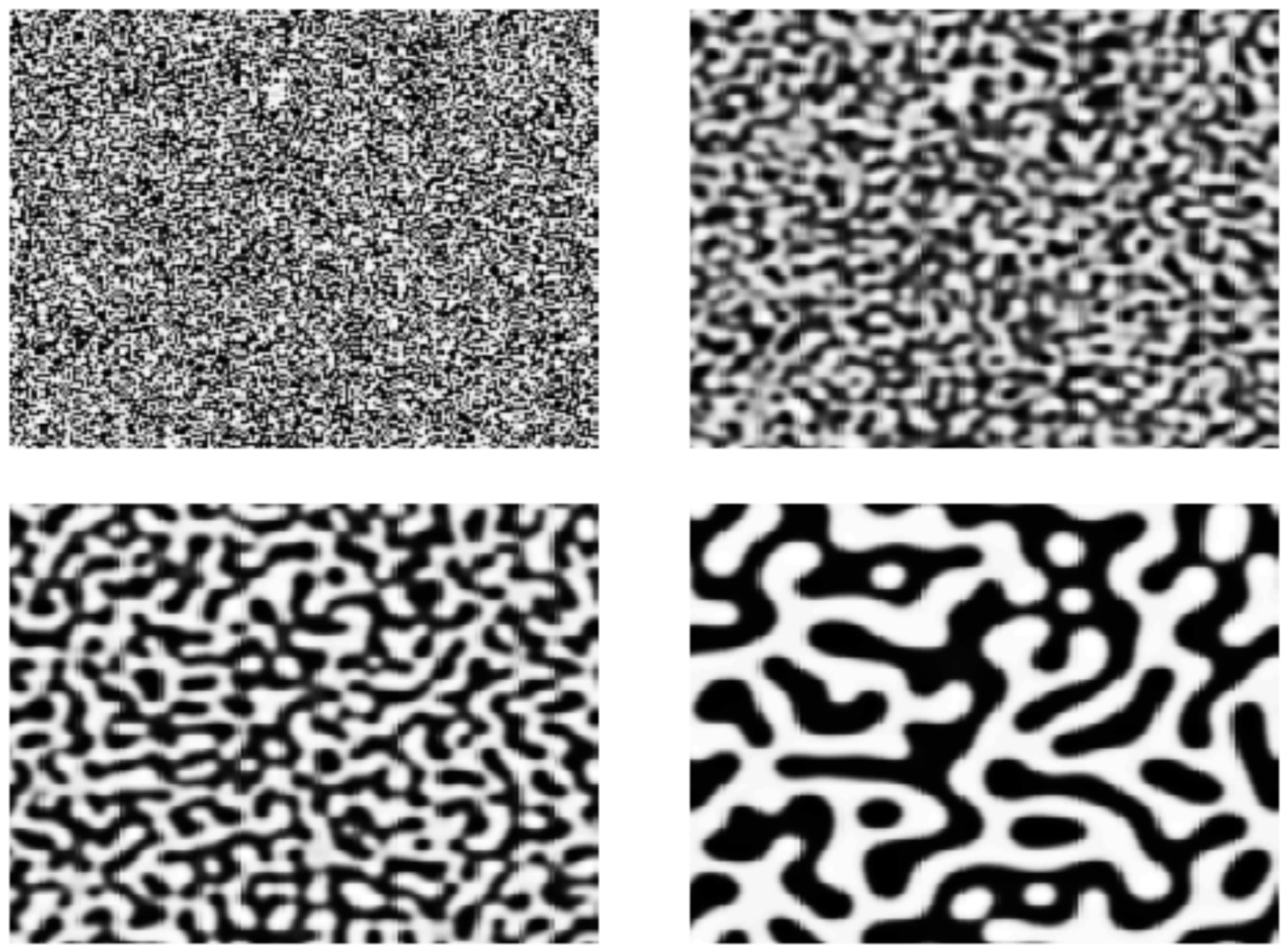
x = 0.55, 0.60, 0.65, macropore size of 8, 4, 1 microns and skeleton thickness of 5, 3, 1 microns have been obtained, respectively (
Figure 2). Increasing the amount of polymer favors silica oligomer aggregation and therefor favors the sol-gel transition. However the monolith obtained for EO unit/Si = 0.65 is fragile due maybe to a lower condensation state of silica with to high interactions between EO unit and silica. In the monolith obtained for EO unit/Si = 0.55, the skeleton of the monolith features additional macropores presumably due to a second phase separation inside the skeleton. The same control of macropore size with increasing amount of EO unit/Si was previously observed for PEO 10 kDa. For a composition mixture 1 Si:~14.5 H
2O:
x EO unit:0.26 HNO
3 where
x = 0.52, 0.59, and 0.63, macropore size of 20, 10 and 4 microns were obtained, respectively [
17]. These authors showed also that increasing the amount of acid decreases the size of the macropores. For a composition mixture 1 Si:~15 H
2O:0.63 EO unit:
x HNO
3 where
x = 0.26 and 0.41, macropore sizes of 4 and 1 microns were obtained, respectively [
17]. Increasing the amount of acid will accelerate the sol-gel transition.
2.1.2. Control of Pressure Drop for Liquid Flow Processes
The control of macropore size and its homogeneity is of paramount importance for liquid flow processes such as separation, catalysis, adsorption, ion-exchange, wastewater treatment,
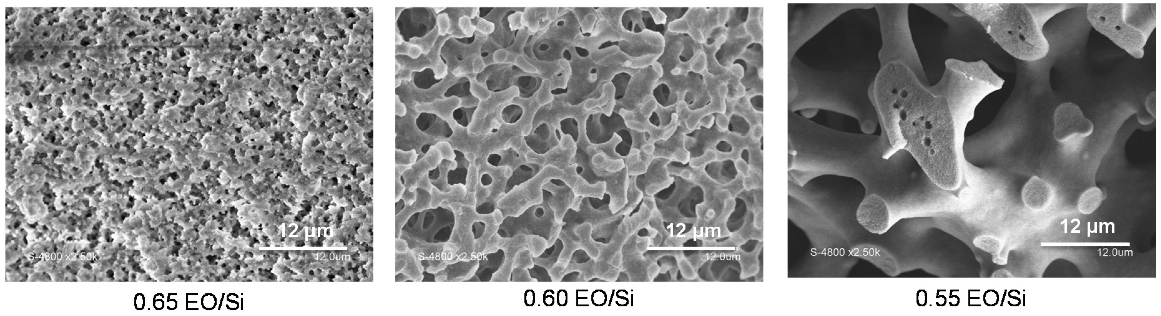
etc. Except in liquid chromatography (where high pressure instruments are used), most applications require materials generating low pressure drops (<1 bar/cm) under flow operation. Establishing relationships between pressure drop and macropore size for materials with macropores shape different from cylindrical shape has barely been attempted and is of prime importance to predict pressure drop in an application. This was done for the first time here in the case of the complex macroporous structure of silica monoliths prepared by phase separation. It has been shown that silica monoliths with hierarchical porosity (macro-/mesoporous) prepared by chemical spinodal decomposition develop laminar flow due to the homogeneous macropore network with, a pressure drop linearly proportional to the flow rate [
17] (
Figure 3). Upon increasing the flow rate, the pressure drop increases dramatically when the size of the macropore decreases (
Figure 3a). Flows through porous media in macroscale have to satisfy empirical Darcy’s law [
18]. Considering a porous medium as a system consisting of straight tubes of diameter
d and length
l, the elementary pressure drop can be described using the well-known Darcy–Weissbach equation:
Due to small liquid velocities in the monolith the friction drag coefficient λ can be calculated from the formula developed for laminar flow using the Reynolds number Re:
where
a is so-called geometrical coefficient and depends on the shape of the flow channel. To eliminate liquid velocity
w from Equation (1), liquid flow rate
(mL/min) can be used together with cross section area
A of the monolith and its volume porosity ε. Using definition formula for Re number (Re
= ρ
dw/η) and the viscosity of the fluid η, the pressure drop equation becomes:
Average pores length
l and monolith unit length
L are not the same due to some stochastic direction changes called tortuosity τ, defined as:
Putting Equation (4) in Equation (3), the pressure drop at given monolith unit length can be expressed as follows:
Although average value of the two geometrical parameters, porosity ε and macropore diameter
d, could be measured by mercury porosimetry, tortuosity τ cannot be separated from the channel shape
a coefficient. Thus for practical reasons, all of these parameters of Equation (5) can be combined in one called Darcy permeability coefficient
K, and the drop pressure equation can be expressed as followed:
where
Darcy permeability coefficient
K given in Equations (6) and (7) enables the comparison of porous materials for a given fluid and its value is relatively easy to determine by plotting pressure drop divided by the length of the monolith as a function of lineic flow, which is the flow (mL/min) divided by the cross section of the monolith (0.28 cm
2 in our case) (
Figure 3b). Macropore sizes of four monoliths prepared by chemical spinodal decomposition have been determined by mercury porosimetry, which gave a distribution of macropore diameter for each monolith: (1) 1–2 μm; (2) 3–6 μm; (3) 10–15 μm; and (4) 20–30 μm. By using water as a model liquid (viscosity: 1.002 mPa·s at 20 °C) under different flow rates, the resulting Darcy permeability coefficient
K were calculated from the slopes of the plots of pressure drop
vs. flow rate (
Figure 3b) and were found equal to 0.21, 0.84, 5.57, and 19.6 μm
2, respectively.
The Darcy permeabilities can be expressed in Darcy (D or μm
2) and are characterized as follows:
Zero and low permeability: <10−6 μm2
Average permeability: 0.015–0.050 μm2
Good permeability: 0.050–0.250 μm2
Very good permeability: 0.250–1 μm2
Excellent permeability: >1 μm2
Therefore the permeability of the silica monoliths is good for macropores size of 1–2 μm, very good for macropores size of 3–6 μm and excellent for macropores size above 10 μm. These monoliths could be used as model materials of porous rocks as their permeability is comparable to sandstone (permeability in the range of 1 Darcy). The permeability depends on numerous features of porosity: pore volume, pore size, pore shape and pore connectivity. In the case of model of parallel cylindrical channels, the permeability can be expressed as:
where ε the porosity equal to the ratio of pore volume and total volume. In the case of monoliths, the shape of the pores is difficult to describe numerically. However, by plotting the square root of
K as a function of macropore diameters (with either the minimum or the maximum limit of macropore size), linear relationships have been found:
for the minimum size of macropore:
for the maximum size of macropore:
Note that the permeability K is not zero for a monolith with no macroporosity. This could be explained by small space between the resin clad and the monolith of ca. 0.5 μm around the monolith.
Using these equations, it is possible to predict the permeability and the pressure drop for monoliths obtained by chemical spinodal decomposition just by knowing their macropore size. The porosity of the silica monoliths is 0.7 < ε < 0.8 if only macropores are taken into account and above ε > 0.9 if mesopore and macropore volumes are considered. As a first approximation, one can use the following simple empirical formula to estimate the permeability of a monolith prepared by chemical spinodal decomposition:
Considering that the smallest macropore size determined by mercury intrusion strongly affect the pressure drop, in first approximation: K = (d/4)2. This value is very close to K = (1/2)(d/4)2 with ε ~1 which is the permeability coefficient for the laminar flow into cylindrical tubes. This means that permeability of silica monoliths prepared by chemical spinodal decomposition, despite their complex macropores network geometry, tends to that of a bunch of cylindrical tubes and that can be attributed to the extensive connectivity of the macropores network.
For catalysis, it has been shown that a ratio of monolith length to monolith diameter of at least 5 is recommended [
19]. Therefore, for 6 mm diameter silica monolith, a minimum length of 3 cm is needed. For applications demanding linear velocities (flow rate divided by monolith cross section) higher than 1 m/h (at least 0.5 mL/min for silica monolith of 6 mm of diameter), all monoliths can be used with a pressure drop lower than 1 bar. For applications requiring a very low pressure drop (<10 mbars), only the monoliths with 20 microns macropores could be used. However, skeleton thickness increases as the same time of macropore size, whereas only thinner skeleton struts enable good internal mass transfer in the mesopores [
1]. Therefore, for macro-/mesoporous monoliths, there is a compromise to find between low pressure drop and high internal mass transfer in the mesoporosity. For many applications, as in catalysis, adsorption or ionic-exchange, we have chosen monoliths featuring macropores of 4 microns and a skeleton thickness of 3 microns to satisfy this compromise [
1].
2.1.3. Influence of Mesopores Shape and Connectivity in Diffusion
The mass transfer in the mesoporosity of materials can be calculated by the Van Deemter equation. A high mass transfer is reached for a low C parameter of the Van Deemter equation, which is proportional to the square of the diffusion length (particle diameter for a packed-bed or the skeleton thickness for the monolith) [
1,
20]. We have shown previously that mass transfer in the mesoporosity is also controlled by the size of the mesopores (or more exactly the ratio mesopore diameter/molecule diameter), the homogeneity of the mesopore size distribution (cylindrical pores and pores with constrictions assimilated to spherical pores) and the interconnectivity of the mesopore network [
1,
20]. The C parameter of the Van Deemter equation is inversely proportional to the diffusion
Diff into the pore:
where
dp the particle diameter or skeleton thickness and
Csm a constant for a given molecule in relation with the affinity of the molecule to the pore.
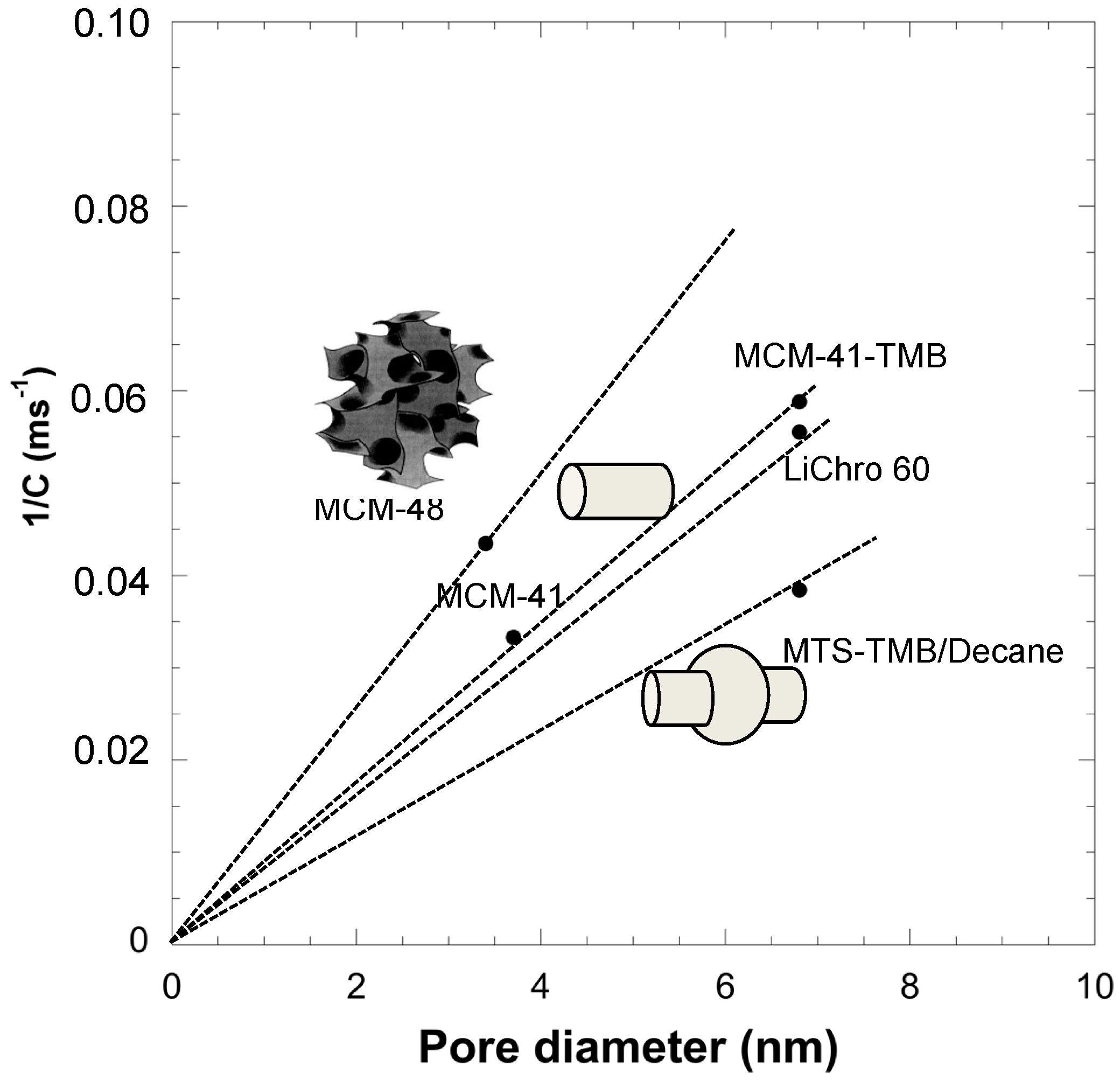
Therefore, the diffusion inside mesopores is proportional to 1/C. Using spherical silica particles of 10 microns and for a given molecule (diethylphtalate), we have shown that diffusion in mesopores increases with the pore diameter, with the presence of interconnections in the mesoporous network and decreases for mesopores featuring constrictions assimilated to spherical cavities. This analysis was done thanks to materials prepared by the pseudomorphic transformation of spherical silica particles (named LiChrospher 60) featuring interconnected spherical pores (cavity 6.8 nm) into either MCM-41 type mesoporosity (cylindrical non-connected pores of 3.7 nm), MCM-48 type mesoporosity (cylindrical interconnected pores of 3.4 nm), MCM-41 swelled with TMB (cylindrical pores of 6.8 nm), or MCM-41 swelled with TMB/decane mixture (unconnected spherical pores with cavities 6.8 nm). It has been shown that diffusion was directly proportional to mesopore sizes (mesopore diameter for cylindrical pores and mesopore cavity for spherical pores) and that a correction
m has to be added for the shape of the pore (
m = 2 for cylindrical pores,
m = 3 for spherical pores) [
21].
By plotting 1/C as a function of pore size (diameter or cavity) we can have an indication of the evolution of the diffusion (as 1/C is proportional to it) and we have determined linear relationships between 1/C (or diffusion) and pore diameters (
Figure 4). The slopes of the lines show the evolution of the diffusion rate as a function of pore size, shape and connectivity. Slopes of 0.0128, 0.0088, 0.0082, and 0.0056 ms
−1·nm
−1 were obtained for cylindrical interconnected pores, cylindrical non-connected pores, spherical interconnected pores, and unconnected spherical pores with cavities, respectively. A general empirical relationship between diffusion, pore size and shape can be proposed by examining these results as:
where A and B are constants, D is the pore diameter or the cavity size, σ is the molecule diameter,
m is the geometrical factor (
m = 2 for cylindrical pore,
m =3 for spherical pore), and
t is the connections factor (
t = 1 for no connections between pores,
t = 1.45 for connections between pores).
For a given pore size, the highest diffusion in mesopores follows the sequence: interconnected cylindrical pores > cylindrical pores ~ interconnected spherical pores > spherical pores. From the discussion above, it appears that it is not only very important to control the size of the mesopores, but also their shape and connectivity in the mesoporous network in order to control the diffusion and, as a consequence, the contact time of any process. Regarding reactivity in catalytic reactions, we have also shown that a compromise should be reached between mesopore size and availability of active surface for the reaction. An optimal mesopore diameter corresponding to around 5–7 times the reactant molecule diameter was found by applying the Ruckenstein rule [
1,
22]. This value corresponds to a same amount of molecules able to adsorb on the surface of the pores and able to diffuse inside the volume of the pore.
2.1.4. Characterization of the Mesoporosity in Hierarchical Silica Monoliths: Pore Size, Pore Shape, Ordering and Connectivity
To understand and control diffusion in silica monoliths, it is important to characterize precisely their mesoporous volume, surface area, mesopore diameter, shape and connectivity. Silica monoliths with hierarchical porosity (meso-/macroporous) have been prepared by a two steps process. The first step is performed in acidic medium where the spinodal decomposition occurs followed by the sol-gel transition to stop the phase separation to form the macroporosity and in the second step the monolith is placed in a basic medium (NH4OH) to generate mesopores by an Ostwald ripening mechanism. The silica network formed in acidic medium is weakly condensed and in basic medium the silica network rearranges into silica nanoparticles, which creates mesopores in the interparticles space. The mesopores diameters depend on the basic temperature and treatment duration.
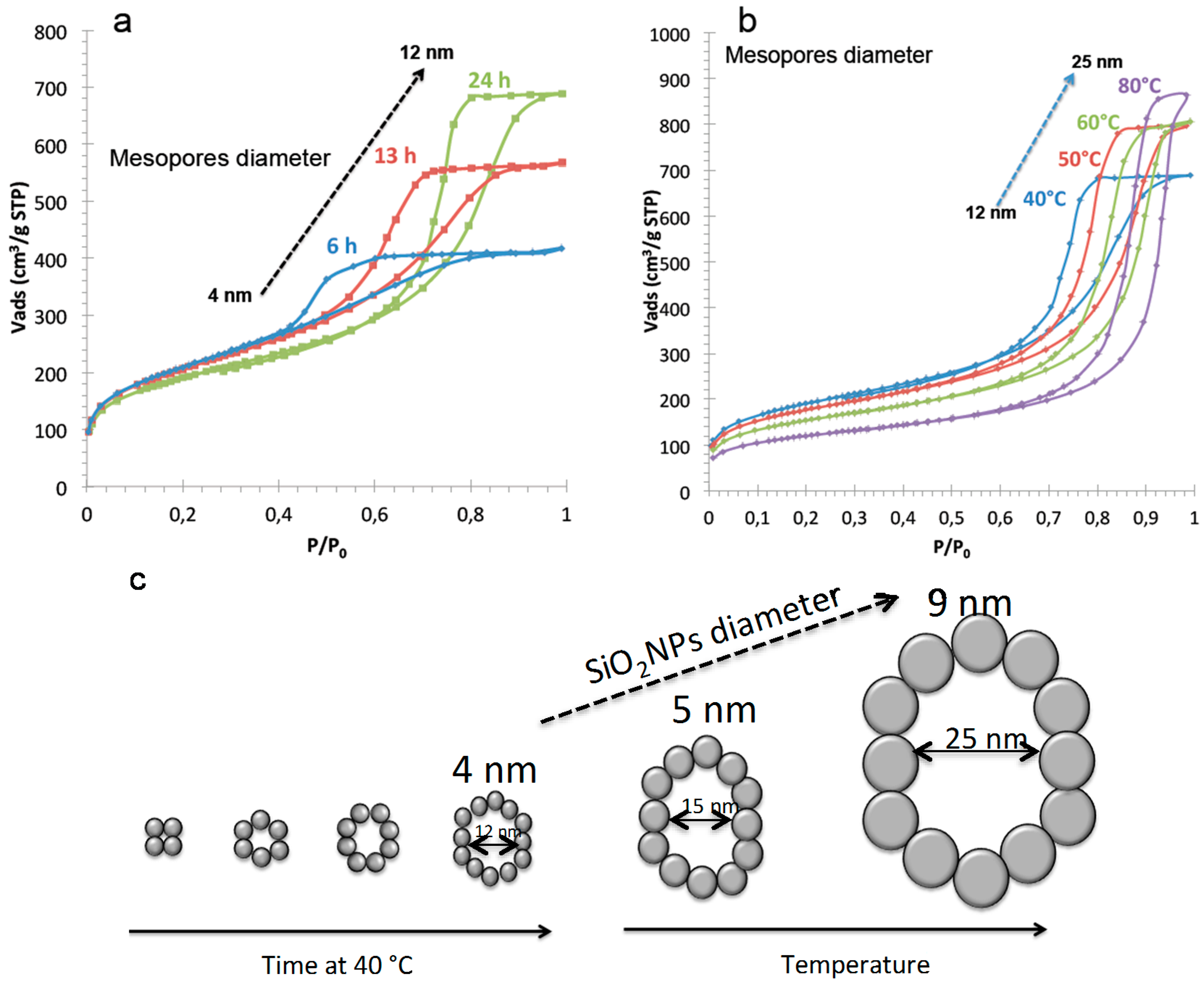
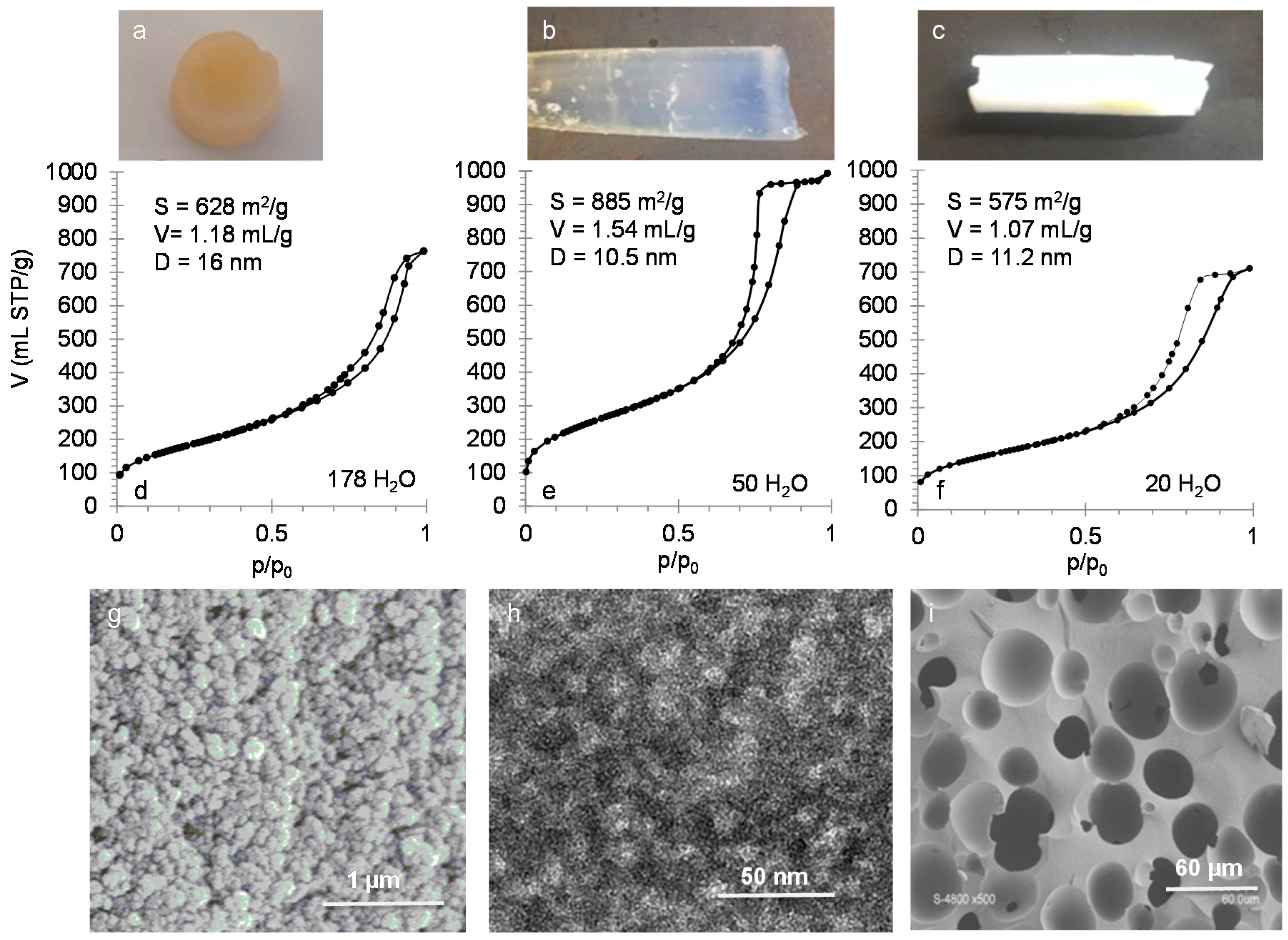
At a constant reaction temperature of 40 °C in NH
4OH, the mesopore diameter increases from 2 to 12 nm for duration of 1 to 24 h with a constant surface area of 700 m
2/g with concomitant increase of pore volume from 0.4 to 1.1 mL/g (
Figure 5). Crack-free monoliths are obtained for treatments durations above 6 h at 40 °C. From the specific surface area
S, we can calculate the average diameter
d of the nanoparticles inside the monolithic skeleton from the formula:
with ρ being the silica density (2.2 g/cm
3)
For
S = 700 m
2/g, the silica nanoparticles diameter is 4 nm. The increase of the mesopore diameter is due to a reorganization of these nanoparticles into larger structures upon basic treatment as shown in
Figure 5. Increasing the basic treatment duration above 24 h will not increase the pore diameter. It seems that the more stable nanoparticles organization is reached when a void equal to ~3 times the size of the nanoparticles is formed. To further increase the mesopore diameter, the temperature of the basic treatment has to be raised. By maintaining the basic treatment duration for 24 h and increasing the temperature from 40 to 80 °C, the mesopore diameters increase from 12 to 25 nm, the pore volumes increase from 1.1 to 1.3 mL/g with a concomitant surface areas decrease from 700 to 400 m
2/g. This corresponds to the increase of silica nanoparticles size from 4 to 9 nm inside the skeleton of the monolith due to Ostwald ripening, but the organization of the nanoparticles remains similar (
Figure 5).
To determine the shape of the mesopores, geometrical pore diameters calculations were performed with the ratio of pore volumes to pore surfaces using the formula:
It is to recall that specific surface areas
S are obtained from the nitrogen isotherm using the BET equation (see below) in which the value of the surface area of the nitrogen molecule is taken as 0.162 nm
2 by default.
To accurately find the linear domain of the BET equation, the use of the Rouquerol criterion [
23] should be applied. This is done by plotting
V(1−
p/p0) =
f(
p/p0) and the first maximum of the curve gives the higher pressure (
p/p0) to use in the BET linear domain. Classically, it is admitted that the BET equation is linear in the domain 0.05 <
p/p0 < 0.35, but for silica materials, the linear domain is mostly 0.1 <
p/p0 < 0.25.
By plotting the BET equation, one can calculate
Vm, the nitrogen monolayer volume, and
CBET parameter from the slope
a and the intercept
b of the plot:
where
is the surface area of the nitrogen molecule at the surface of the material,
n is the number of nitrogen molecules,
is the molar volume of nitrogen (22.414 L/mol), and
NA is the Avogadro number (6.025 × 10
23 molecule/moles). As
Vm is expressed as gas volume in mL STP/g, the surface area becomes:
and for
= 0.162 nm
2,
SBET (m
2/g) = 4.36
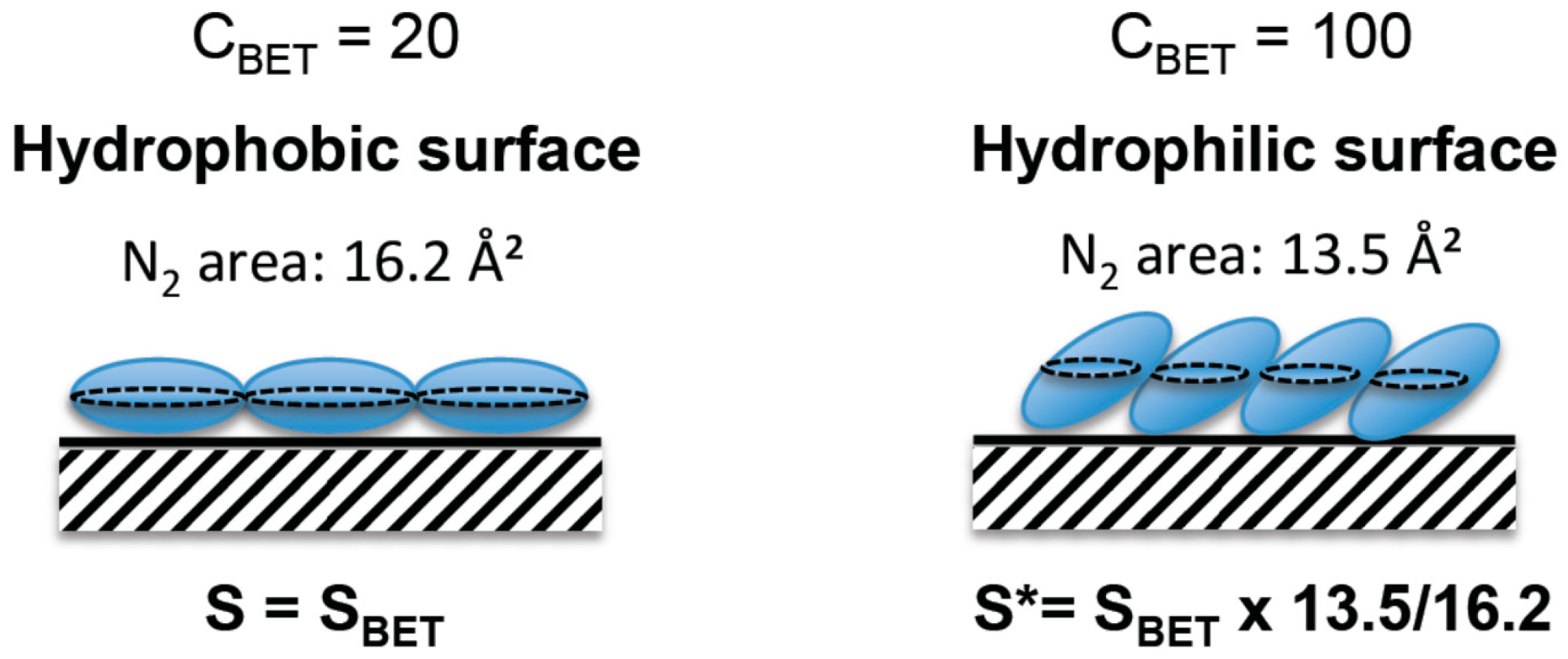
VmHowever, it has been shown that the surface area of a nitrogen molecule is not constant, it changes in function of its interaction with the material surface, as the nitrogen molecule is not spherical but cylindrical [
13]. For weak surface interactions, as for nitrogen on organic grafted material or hydrophobic materials, the nitrogen molecules lay on the surface, leading to a surface area projection of 0.162 nm
2, whereas the molecule is more perpendicular to the surface on hydrophilic materials due to stronger affinity and therefore a closer packing, leading to a surface projection close to 0.135 nm
2 (
Figure 6). The affinity of nitrogen with the surface can be evaluated by the energy of first layer adsorption of nitrogen molecules on the material surface, which is included in the calculation of the
CBET parameter from the BET equation [
24].
where α is a constant (α > 0),
E1 is the energy of adsorption of nitrogen on the surface (first layer) and
EL is the energy of adsorption of the other nitrogen layers assimilated to nitrogen liquefaction energy [
24].
CBET is characteristic of adsorbate/material interactions and increases when interactions strength increases. For instance, nitrogen molecules interact strongly with hydrophilic surfaces corresponding to
CBET ~ 100, whereas for hydrophobic surfaces (as octyl-grafted silicas) [
25,
26] the interactions are weaker (
CBET ~ 20) and the projection of the surface area of a nitrogen molecule change from 0.135 to 0.162 nm
2, respectively. For 20–30 <
CBET < 90–100, corresponding to hydrophobic–hydrophilic surfaces, the surface of a nitrogen molecules will be 0.135 <
< 0.162 nm
2. Some corrections of BET surface areas are therefore needed to evaluate the surface area of hydrophilic materials such as silicas. Classical silica materials, as silica monoliths, with silanols on their surface, are hydrophilic (
CBET > 90), so corrections of specific BET surface area
SBET coming from the instrument are needed and the surface area become
S* using the following formula:
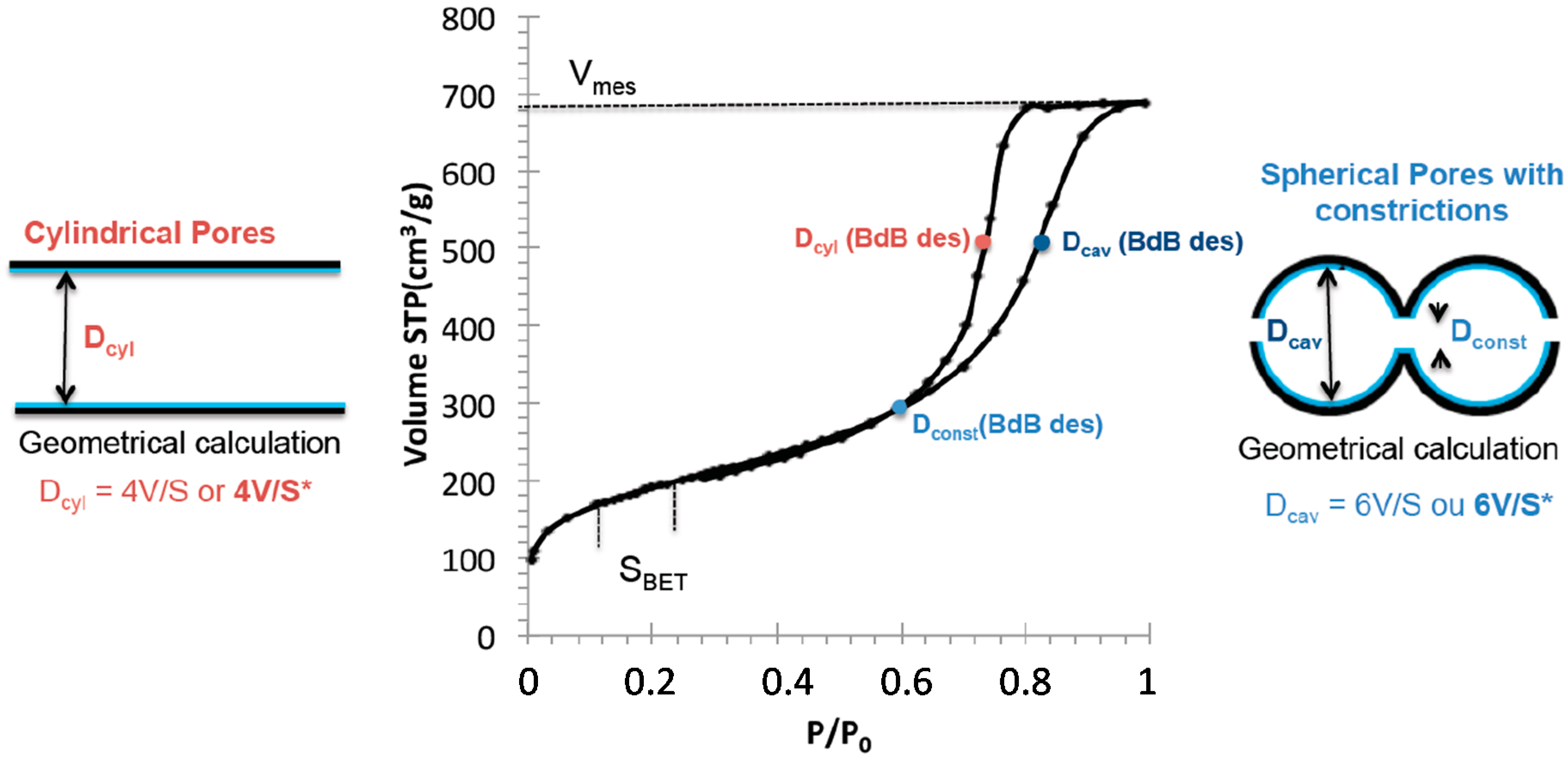
The geometrical mesopore diameter becomes therefore either equal to 4
V/
S* for cylindrical pores or to 6
V/
S* for spherical pores. Pore volumes are taken at the end of the capillary condensation step (
Figure 7). For silica monoliths, geometrical pores determination have been compared with mesopore diameters calculated from the capillary condensation pressure using the Broekhoff and De Boer method [
27], which proved to be the most accurate method derived from Kelvin equation for mesopore diameter determination. Broekhoff and De Boer method has been proposed for cylindrical pores. However, mesopore size determination is impacted by the shape of the pore and is different for cylindrical and spherical pores. For cylindrical pores, the mesopore diameter is calculated by using the desorption branch of the isotherm and BdB desorption is applied to the mean pressure of desorption. For spherical pores, the constriction diameter of the pore is calculated from the pressure of the closing point of the hysteresis by applying the BdB desorption and the cavity size is calculated from the adsorption branch of the isotherm by applying the BdB desorption to the mean pressure of adsorption (
Figure 7). This observation has been confirmed by simulation experiments on various shapes of pores [
28,
29,
30].
The use of BdB desorption to the adsorption branch in the case of spherical pores can be explained with the Kelvin equation for cylindrical and spherical pores. Indeed, the Kelvin equation is expressed as:
with
where γ is the surface tension of nitrogen at the solid surface,
VL is the molar volume, and
rk describes the curvature of the adsorbate layer at the surface of the pore in two directions: along the pore
r1 and perpendicular to the pore
r2.
For a cylindrical pore, during the desorption, the curvature meniscus is spherical and
r1 =
r2 =
r,
r being the pore radius of the pore and therefore
rkdes(cylinder) =
r. For spherical pores, during adsorption, the adsorbed layer is spherical and
r1 =
r2 =
r with r the radius of the cavity and therefore
rkads(sphere) =
r. Therefore the Kelvin equation is the same for the adsorption in spherical pores with cavity of radius r and for the desorption in cylindrical pores of radius r. It is precise that the radius
rk determined by the Kelvin equation is not directly the pore diameter
rp as it is only calculated from pore filling. To obtain the pore diameter, the thickness
t of the adsorbed layer before capillary condensation has to be added (BJH method):
The thickness of the adsorbed layer can be evaluated experimentally with a non-porous silica [
31] or less accurately calculated from different formula as De Boer equation:
This represents the BJH method, which has been shown to underestimate the pore diameter by 20% for hydrophilic silica. This is due to the fact that in Kelvin equation the surface tension has been taken as a constant and it is in fact depending on the curvature of the pores for pore diameter inferior to 30 nm [
24]:
where
rk is expressed in nm and
is the surface tension measured for a flat infinite surface.
The BJH method with surface tension correction is in good agreement with the results found by the BdB method [
13].
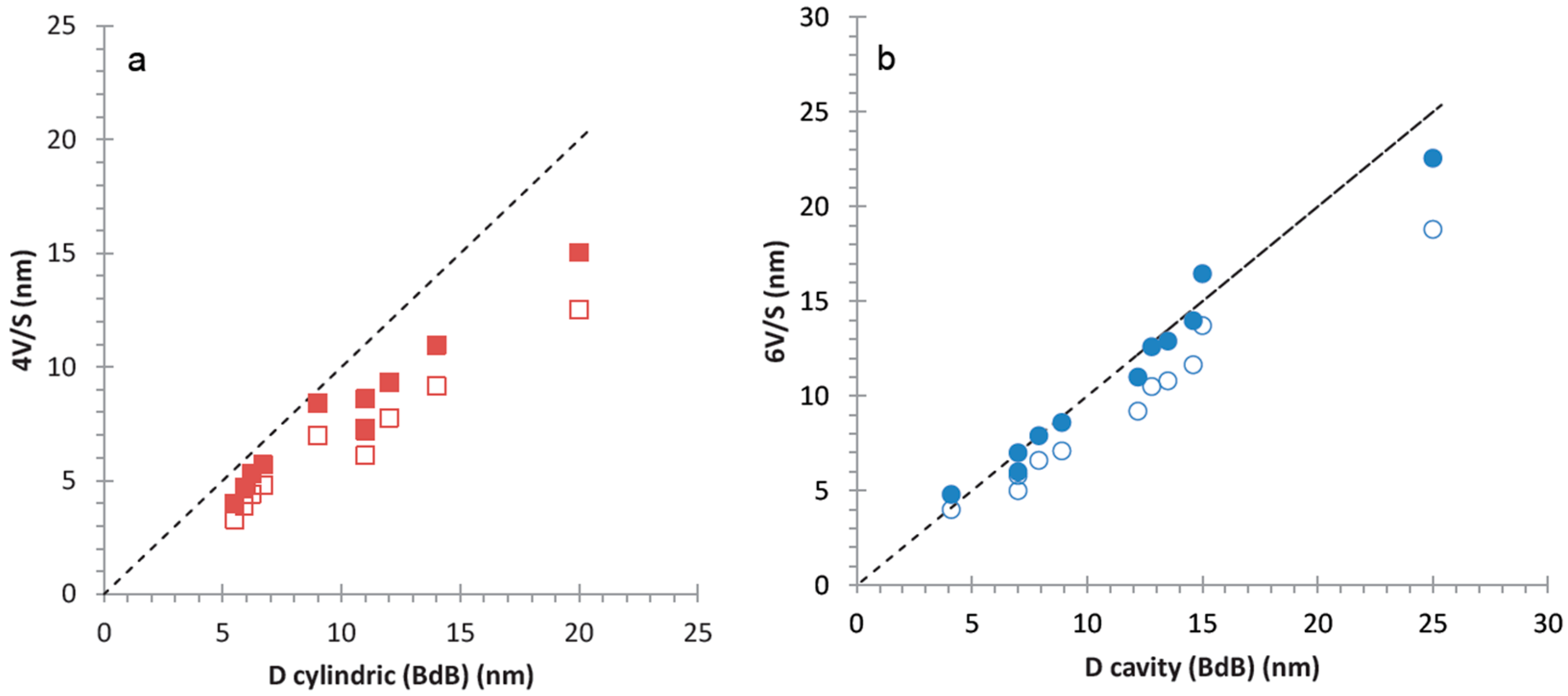
To evaluate precisely the size and the shape of the mesopores in hierarchical silica monoliths, geometrical pores diameter assuming spherical or cylindrical pores (6
V/
S* or 4
V/
S*), respectively, have been compared to the pore sizes determined from the average pressures of the steps of the adsorption branch (by applying BdB desorption) for spherical pores and of the desorption branch (by applying BdB desorption) for cylindrical pores, respectively (
Figure 8). In
Figure 8, values of 6
V/
S and 4
V/
S have been included for comparison (open markers in
Figure 8). For silica monoliths with different mesopores diameters, the best fit between capillary condensation pressures and geometrical calculations have been obtained for 6
V/
S* revealing that the mesopores in silica monolith are of spherical shape with cavities sizes from 4 to 26 nm. This shape corresponds to the lowest diffusion properties of molecules into a material (see
Section 2.1.3).
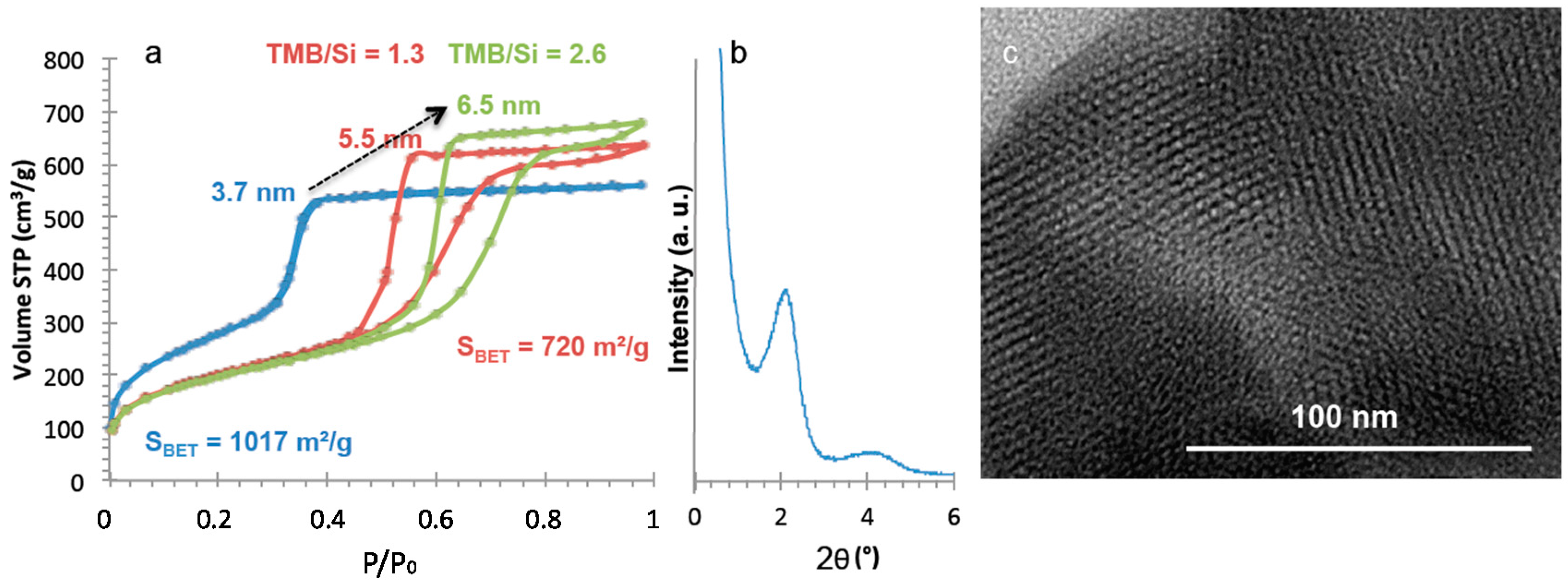
To increase diffusion, cylindrical pores are needed. In order to form mesopores with cylindrical shape, the second alkaline step (NH
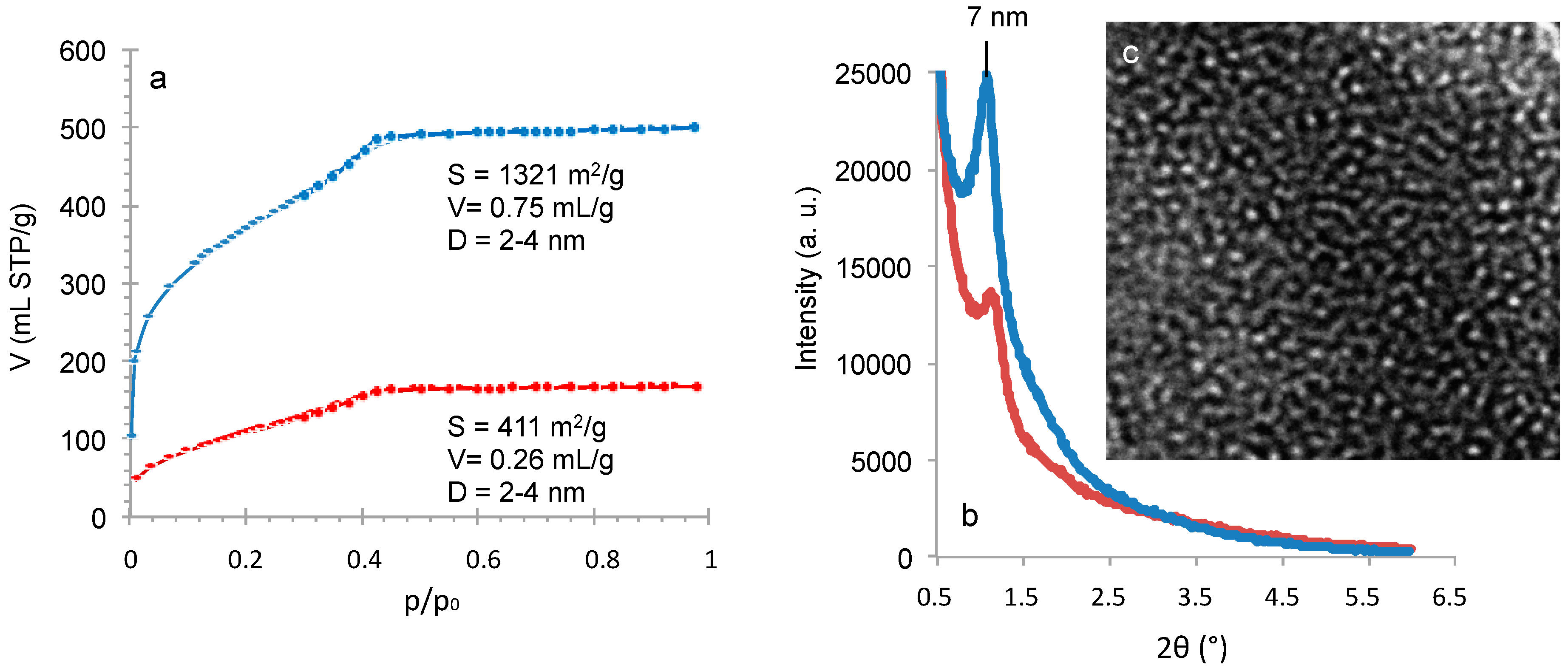
4OH treatment) of the monolith preparation was modified by replacing ammonia by a surfactant-templating agent (cetyltrimethyl ammonium bromide in NaOH solution) to form a MCM-41 like mesoporosity. The resulting nitrogen isotherm at 77 K (
Figure 9) is characteristic of MCM-41 like mesoporosity with a sharp step in adsorption revealing uniform pores of 3.7 nm of diameter, a surface area of 1017 m
2/g and a pore volume of 0.86 mL/g. XRD pattern shows one peak at 2 θ around 2° (
Figure 9) corresponding to a cell parameter
a0 of 4.85 nm and a wall-thickness of 1.1 nm with a second large peak usually found for worm-like structure of pores. TEM pictures show that some portions of the monolith are in hexagonal organization as expected for MCM-41 (
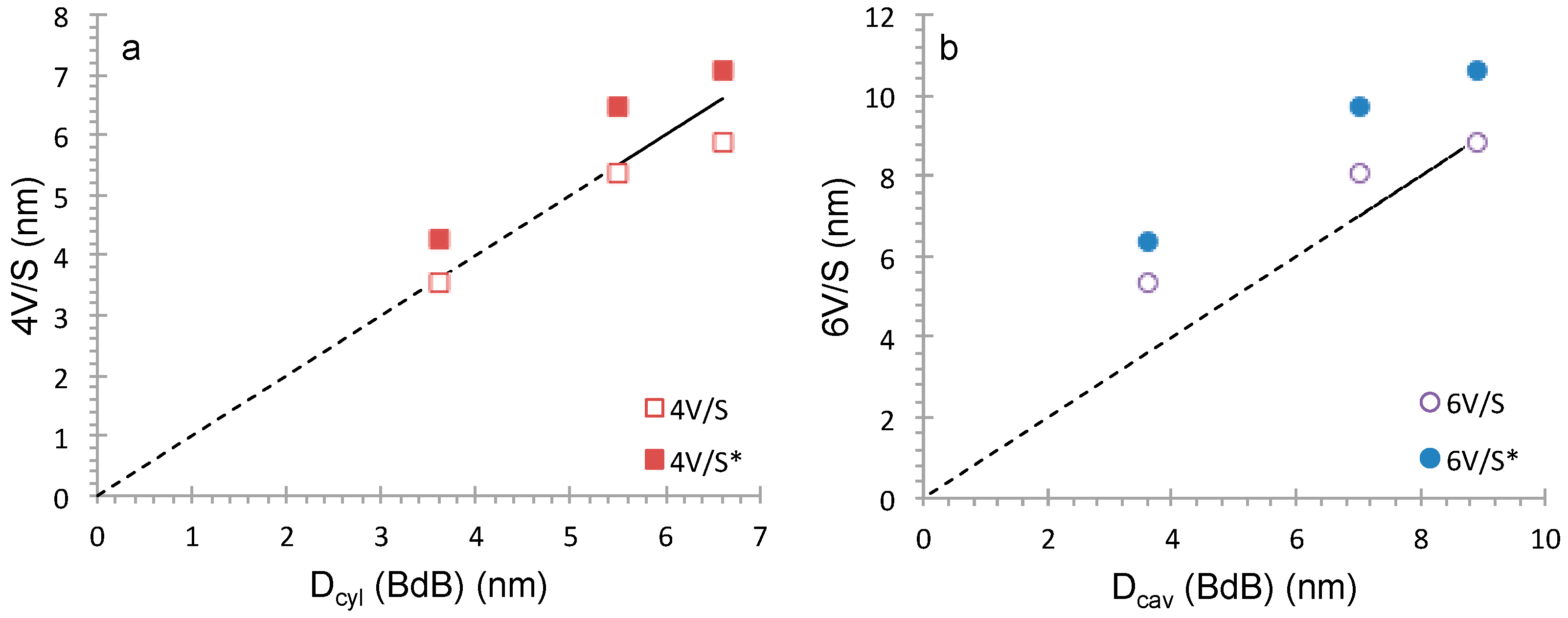
Figure 9), but also some wormlike domains. In order to increase the mesopore diameter, a swelling agent 1,3,5-trimethylbenzene (TMB) was added to the synthesis medium and pores of 5.5 and 6.6 nm have been obtained by increasing the TMB amount (
Figure 9). The shape of the pores has been checked as previously by comparing geometrical calculations (4
V/
S and 6
V/
S) to the pressure of capillary condensation using BdB method (
Figure 10). The more accurate correlation is obtained for 4
V/
S ratio in accordance with cylindrical pores. However, due to the hydrophilic surface of the materials (
CBET = 90–100) it is surprising that the correlation is not 4
V/
S* as usually found for MCM-41 prepared from silica alkoxide or silica powder (
Table 1) [
13]. The same feature is observed for other ordered mesoporous surfactant-templating silica powders such as HMS [
32] with a worm-like structure and MCM-48 [
33] with a cubic structure featuring both cylindrical pores with interconnections between pores (
Table 1). The interconnections in a porous material add supplementary volumes in comparison to independent cylindrical pores, which false the geometrical calculation of cylindrical pores. By taking into account the mesopore diameter obtained by BdB method, the volume of the cylindrical pores and the volume of the connections can be evaluated (
Table 2):
In MCM-41 like monoliths, the volume of interconnections represent 10%–15% of the total volume, which is close to MCM-48 materials (12% of total pore volume) and slightly below HMS materials revealing the highest degree of connectivity (20% of total pore volume) (
Table 2). MCM-41-like Monolith synthesized with the higher amount of TMB possess pores with spherical shape and interconnections (12% of total pore volume) as observed in the correlation in
Figure 10. MCM-41 like monoliths are therefore highly suitable for fast diffusion application. In summary, if silica materials are hydrophilic (
CBET = 90–100) and the correlation with geometrical calculation is closer to 4
V/
S or 6
V/
S, it is an indication of interconnectivity in the material. These calculations may constitute therefore an original, simple and reliable method to determine the degree of mesopores connectivity in materials.


