
Transforming Capillary Alginate Gel (Capgel) into New 3D-Printing Biomaterial Inks

 , , and
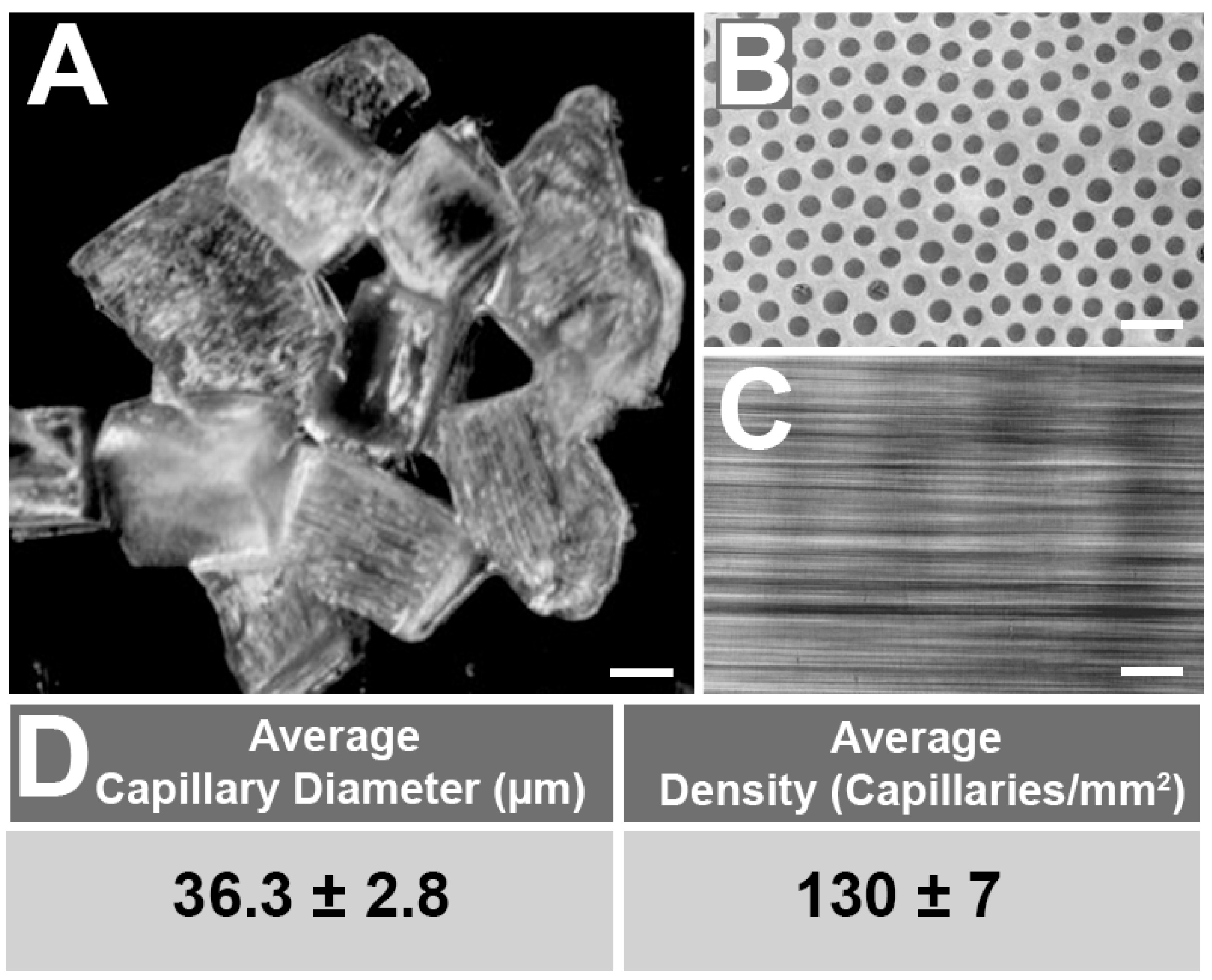
Abstract
:1. Introduction
2. Results and Discussion
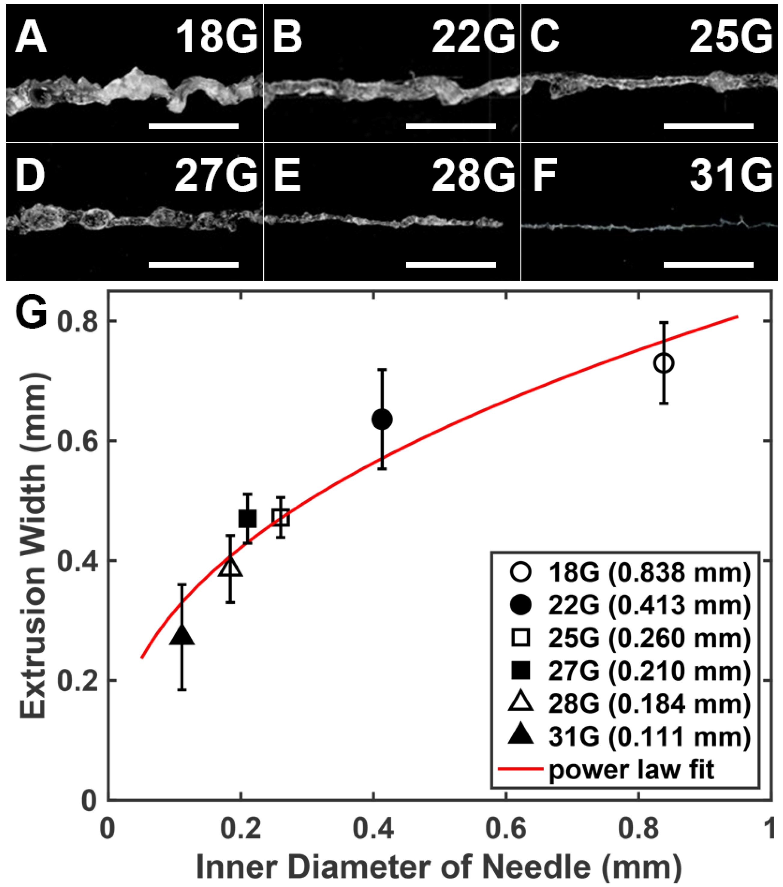
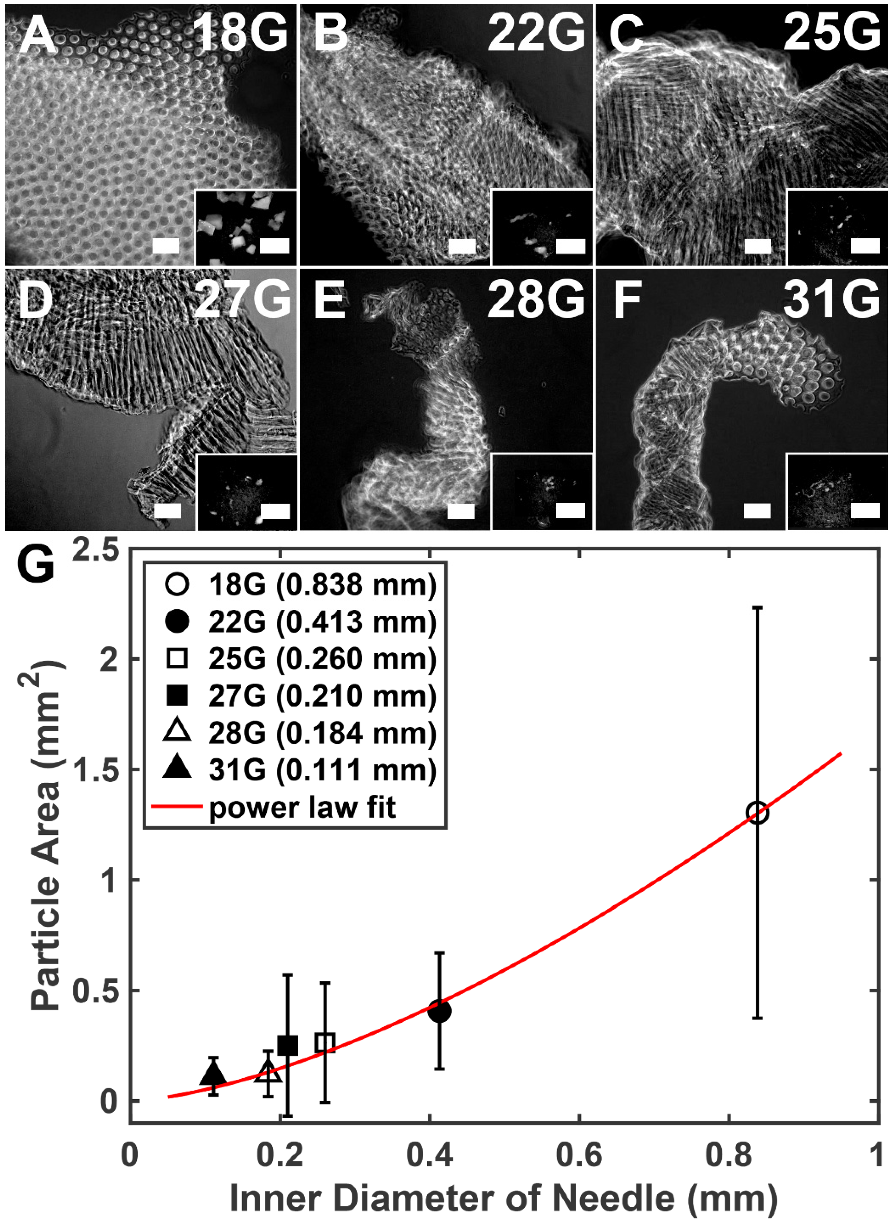
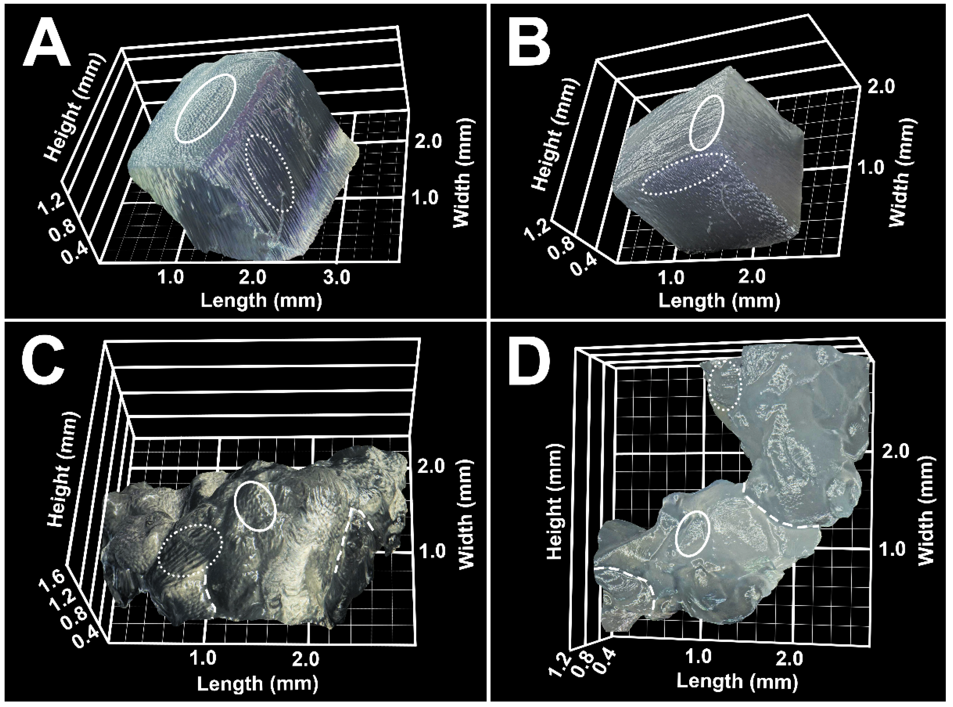
2.1. Capgel Ink Needle Extrusions
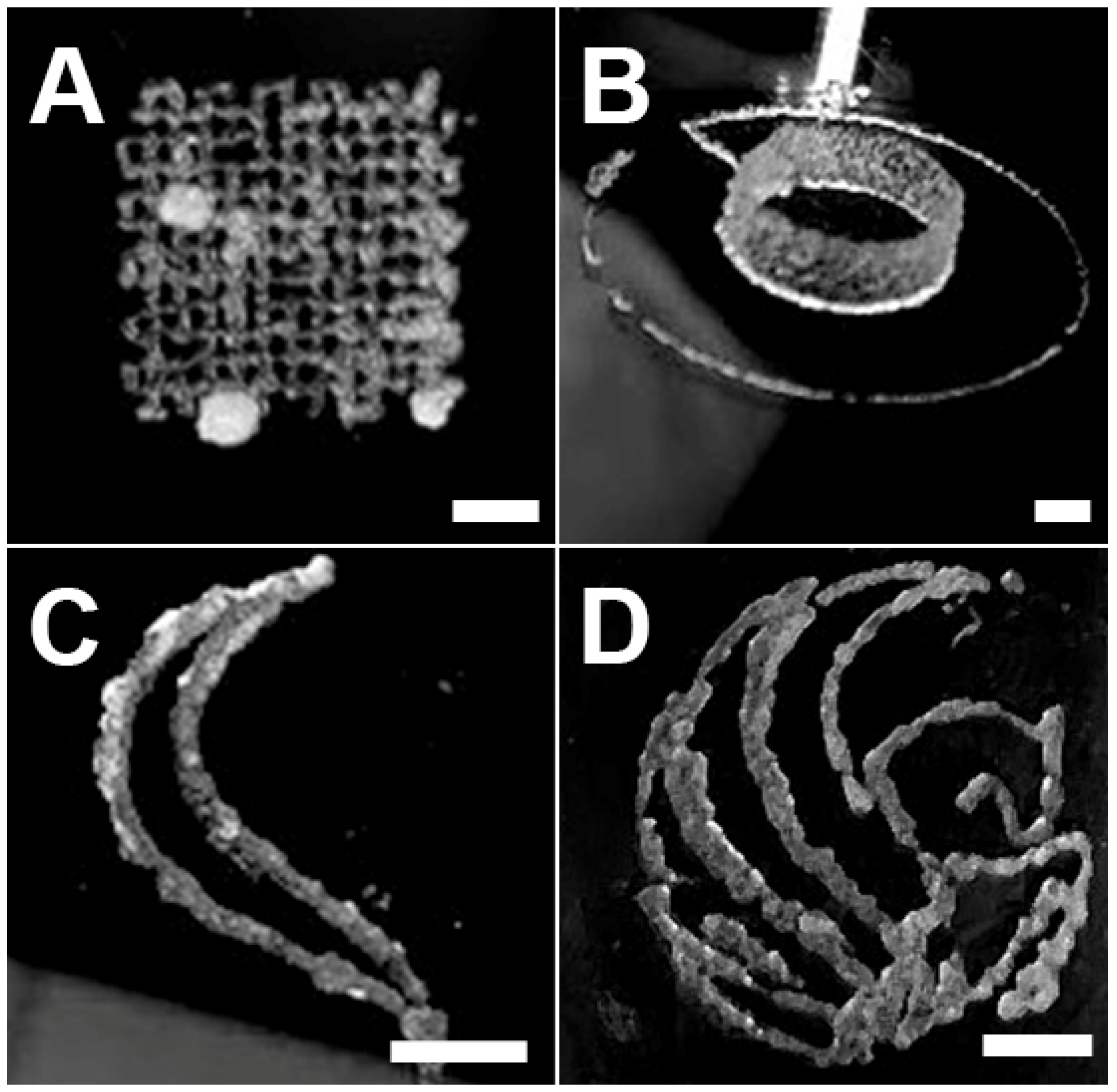
2.2. 3D Printing with Capgel Ink
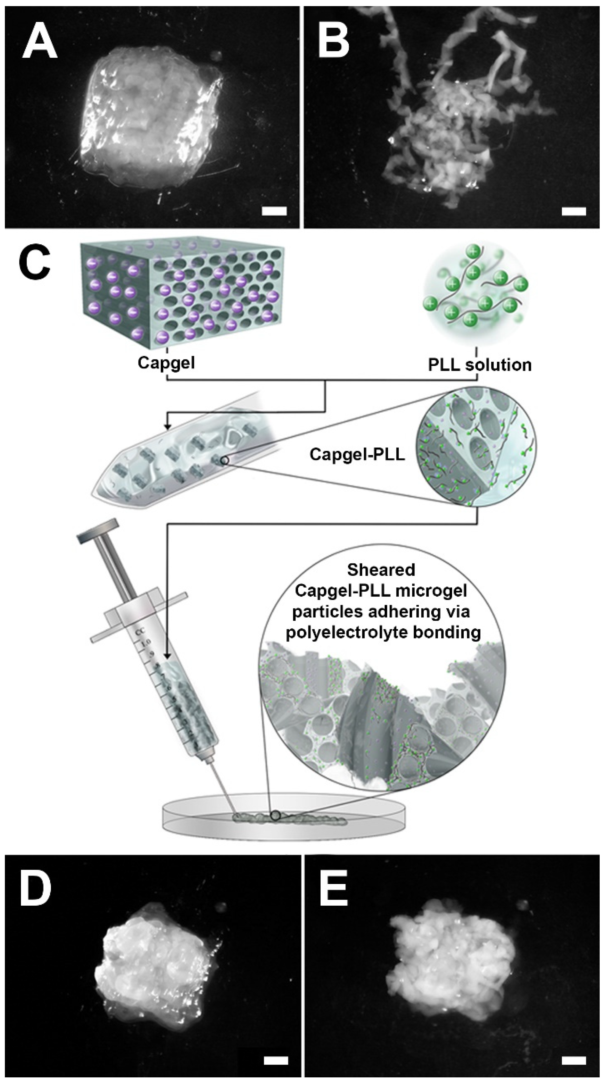
2.3. Development of Capgel-PLL Ink
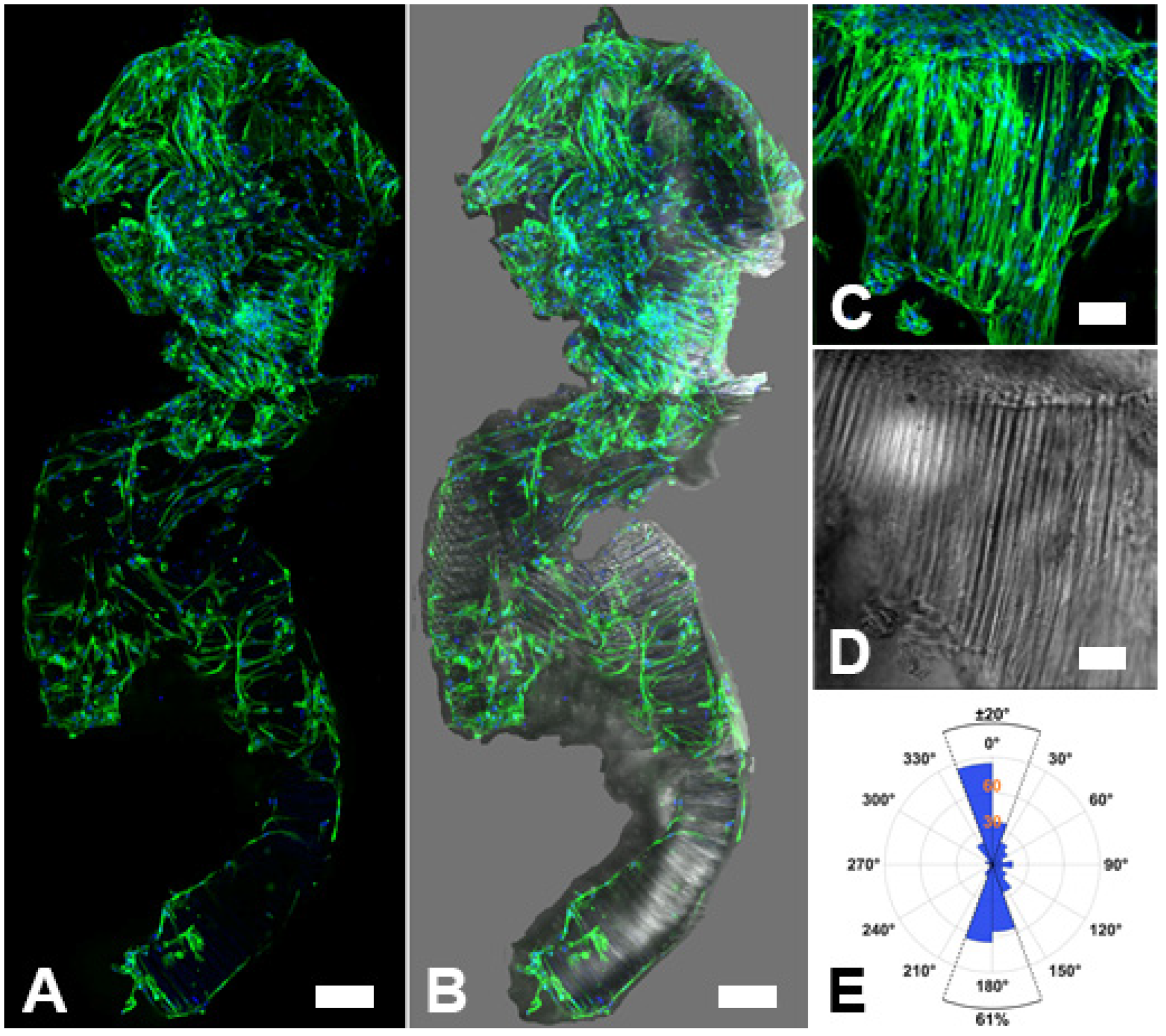
2.4. Biocompatibility of Capgel-PLL Ink
3. Conclusions
4. Materials and Methods
4.1. Formation and Growth of Capgel Hydrogels
4.2. Crosslinking and Preparation of Capgel Blocks
4.3. Capgel Capillary, Particle Size, and Extrusion Analysis
4.4. 3D Printer Settings and Methods
4.5. Poly-L-Lysine Coating of Capgel (Capgel-PLL)
4.6. Digital 3D Reconstruction of Capgel and Capgel-PLL Pieces and Extrusions
4.7. Cultivation and Preparation of HLF Cells
4.8. Post-Extrusion Cell Seeding of Extruded Capgel-PLL, Histological Staining, and Image Processing
Supplementary Materials
Author Contributions
Funding
Institutional Review Board Statement
Informed Consent Statement
Data Availability Statement
Acknowledgments
Conflicts of Interest
References
- Saidi, R.F.; Kenari, S.H. Challenges of Organ Shortage for Transplantation: Solutions and Opportunities. Int. J. Organ Transpl. Med. 2014, 5, 87–96. [Google Scholar]
- Langer, R.; Vacanti, J.P. Tissue Engineering. Science 1993, 260, 920–926. [Google Scholar] [CrossRef] [PubMed] [Green Version]
- Kean, T.J.; Thanou, M. Utility of Chitosan for 3D Printing and Bioprinting. In Sustainable Agriculture Reviews; Crini, G.L.E., Ed.; Springer: Cham, Switzerland, 2019; p. 271. [Google Scholar]
- Gungor-Ozkerim, P.S.; Inci, I.; Zhang, Y.S.; Khademhosseini, A.; Dokmeci, M.R. Bioinks for 3D bioprinting: An overview. Biomater. Sci. 2018, 6, 915–946. [Google Scholar] [CrossRef] [PubMed] [Green Version]
- Carvalho, V.; Goncalves, I.; Lage, T.; Rodrigues, R.O.; Minas, G.; Teixeira, S.; Moita, A.S.; Hori, T.; Kaji, H.; Lima, R.A. 3D Printing Techniques and Their Applications to Organ-on-a-Chip Platforms: A Systematic Review. Sensors 2021, 21, 3304. [Google Scholar] [CrossRef]
- Holzl, K.; Lin, S.; Tytgat, L.; van Vlierberghe, S.; Gu, L.; Ovsianikov, A. Bioink properties before, during and after 3D bioprinting. Biofabrication 2016, 8, 032002. [Google Scholar] [CrossRef] [Green Version]
- Muraoka, M.; Shimizu, T.; Itoga, K.; Takahashi, H.; Okano, T. Control of the formation of vascular networks in 3D tissue engineered constructs. Biomaterials 2013, 34, 696–703. [Google Scholar] [CrossRef] [PubMed]
- Axpe, E.; Oyen, M.L. Applications of Alginate-Based Bioinks in 3D Bioprinting. Int. J. Mol. Sci. 2016, 17, 1976. [Google Scholar] [CrossRef] [Green Version]
- Auger, F.A.; Gibot, L.; Lacroix, D. The pivotal role of vascularization in tissue engineering. Annu. Rev. Biomed. Eng. 2013, 15, 177–200. [Google Scholar] [CrossRef]
- Shah, P.P.; Shah, H.B.; Maniar, K.K.; Ozel, T. Extrusion-based 3D bioprinting of alginate-based tissue constructs. Procedia CIRP 2020, 95, 143–148. [Google Scholar] [CrossRef]
- Parak, A.; Pradeep, P.; du Toit, L.C.; Kumar, P.; Choonara, Y.E.; Pillay, V. Functionalizing bioinks for 3D bioprinting applications. Drug Discov. Today 2019, 24, 198–205. [Google Scholar] [CrossRef] [PubMed]
- Highley, C.B.; Song, K.H.; Daly, A.C.; Burdick, J.A. Jammed Microgel Inks for 3D Printing Applications. Adv. Sci. 2019, 6, 1801076. [Google Scholar] [CrossRef] [PubMed] [Green Version]
- Mealy, J.E.; Chung, J.J.; Jeong, H.H.; Issadore, D.; Lee, D.; Atluri, P.; Burdick, J.A. Injectable Granular Hydrogels with Multifunctional Properties for Biomedical Applications. Adv. Mater. 2018, 30, e1705912. [Google Scholar] [CrossRef]
- Muir, V.G.; Qazi, T.H.; Shan, J.; Groll, J.; Burdick, J.A. Influence of Microgel Fabrication Technique on Granular Hydrogel Properties. ACS Biomater. Sci. Eng. 2021, 7, 4269–4281. [Google Scholar] [CrossRef] [PubMed]
- Bosak, A.; Kwan, M.W.C.; Willenberg, A.; Perle, K.M.D.L.; Weinstein, D.; Hines, R.B.; Schultz, G.S.; Ross, E.A.; Willenberg, B.J. Capillary alginate gel (Capgel™) for the treatment of full-thickness dermal wounds in a hypoxic mouse model. Int. J. Polym. Mater. Polym. Biomater. 2018, 68, 1108–1117. [Google Scholar] [CrossRef]
- Rocca, D.G.; Willenberg, B.J.; Qi, Y.; Simmons, C.S.; Rubiano, A.; Ferreira, L.F.; Huo, T.; Petersen, J.W.; Ruchaya, P.J.; Wate, P.S.; et al. An injectable capillary-like microstructured alginate hydrogel improves left ventricular function after myocardial infarction in rats. Int. J. Cardiol. 2016, 220, 149–154. [Google Scholar] [CrossRef] [PubMed] [Green Version]
- Anderson, W.A.; Willenberg, A.R.; Bosak, A.J.; Willenberg, B.J.; Lambert, S. Use of a capillary alginate gel (Capgel) to study the three-dimensional development of sensory nerves reveals the formation of a rudimentary perineurium. J. Neurosci. Methods 2018, 305, 46–53. [Google Scholar] [CrossRef]
- George, D.S.; Anderson, W.A.; Sommerhage, F.; Willenberg, A.R.; Hines, R.B.; Bosak, A.J.; Willenberg, B.J.; Lambert, S. Bundling of axons through a capillary alginate gel enhances the detection of axonal action potentials using microelectrode arrays. J. Tissue Eng. Regen. Med. 2019, 13, 385–395. [Google Scholar] [CrossRef]
- Willenberg, B.J.; Hamazaki, T.; Meng, F.W.; Terada, N.; Batich, C. Self-assembled copper-capillary alginate gel scaffolds with oligochitosan support embryonic stem cell growth. J. Biomed. Mater. Res. A 2006, 79, 440–450. [Google Scholar] [CrossRef]
- Willenberg, B.J.; Zheng, T.; Meng, F.W.; Meneses, J.C.; Rossignol, C.; Batich, C.D.; Terada, N.; Steindler, D.A.; Weiss, M.D. Gelatinized copper-capillary alginate gel functions as an injectable tissue scaffolding system for stem cell transplants. J. Biomater. Sci. Polym. Ed. 2011, 22, 1621–1637. [Google Scholar] [CrossRef] [Green Version]
- Magin, C.M.; Neale, D.B.; Drinker, M.C.; Willenberg, B.J.; Reddy, S.T.; La Perle, K.M.; Schultz, G.S.; Brennan, A.B. Evaluation of a bilayered, micropatterned hydrogel dressing for full-thickness wound healing. Exp. Biol. Med. 2016, 241, 986–995. [Google Scholar] [CrossRef] [PubMed] [Green Version]
- Lee, K.Y.; Mooney, D.J. Alginate: Properties and biomedical applications. Prog. Polym. Sci. 2012, 37, 106–126. [Google Scholar] [CrossRef] [PubMed] [Green Version]
- Neufurth, M.; Wang, X.; Schroder, H.C.; Feng, Q.; Diehl-Seifert, B.; Ziebart, T.; Steffen, R.; Wang, S.; Muller, W.E.G. Engineering a morphogenetically active hydrogel for bioprinting of bioartificial tissue derived from human osteoblast-like SaOS-2 cells. Biomaterials 2014, 35, 8810–8819. [Google Scholar] [CrossRef] [PubMed]
- Zhang, T.; Yan, K.C.; Ouyang, L.; Sun, W. Mechanical characterization of bioprinted in vitro soft tissue models. Biofabrication 2013, 5, 045010. [Google Scholar] [CrossRef]
- Yang, F.; Cohen, R.N.; Brey, E.M. Optimization of Co-Culture Conditions for a Human Vascularized Adipose Tissue Model. Bioengineering 2020, 7, 114. [Google Scholar] [CrossRef]
- Du, P.; Suhaeri, M.; Ha, S.S.; Oh, S.J.; Kim, S.H.; Park, K. Human lung fibroblast-derived matrix facilitates vascular morphogenesis in 3D environment and enhances skin wound healing. Acta Biomater. 2017, 54, 333–344. [Google Scholar] [CrossRef]
- Sugihara, K.; Yamaguchi, Y.; Usui, S.; Nashimoto, Y.; Hanada, S.; Kiyokawa, E.; Uemura, A.; Yokokawa, R.; Nishiyama, K.; Miura, T. A new perfusion culture method with a self-organized capillary network. PLoS ONE 2020, 15, e0240552. [Google Scholar] [CrossRef] [PubMed]
- Zeinali, S.; Bichsel, C.A.; Hobi, N.; Funke, M.; Marti, T.M.; Schmid, R.A.; Guenat, O.T.; Geiser, T. Human microvasculature-on-a chip: Anti-neovasculogenic effect of nintedanib in vitro. Angiogenesis 2018, 21, 861–871. [Google Scholar] [CrossRef] [Green Version]
- Zhang, Y.; Yu, Y.; Akkouch, A.; Dababneh, A.; Dolati, F.; Ozbolat, I.T. In Vitro Study of Directly Bioprinted Perfusable Vasculature Conduits. Biomater. Sci. 2015, 3, 134–143. [Google Scholar] [CrossRef]
- Schwab, A.; Levato, R.; D’Este, M.; Piluso, S.; Eglin, D.; Malda, J. Printability and Shape Fidelity of Bioinks in 3D Bioprinting. Chem. Rev. 2020, 120, 11028–11055. [Google Scholar] [CrossRef]
- Constantrinidis, I.; Grant, S.C.; Celper, S.; Gauffin-Holmberg, I.; Agering, K.; Oca-Cossio, J.A.; Bui, J.D.; Flint, J.; Hamaty, C.; Simpson, N.E.; et al. Non-invasive evaluation of alginate/Poly-L-lysine/Alginate Microcapsules by Magnetic Resonance Microscopy. Biomaterials 2007, 28, 2438–2445. [Google Scholar] [CrossRef] [Green Version]
- Virumbrales-Munoz, M.; Santos-Vizcaino, E.; Paz, L.; Gallardo-Moreno, A.M.; Orive, G.; Hernandez, R.M.; Doblare, M.; Gonzalez-Martin, M.L.; Fernandez, L.J.; Pedraz, J.L.; et al. Force spectroscopy-based simultaneous topographical and mechanical characterization to study polymer-to-polymer interactions in coated alginate microspheres. Sci. Rep. 2019, 9, 20112. [Google Scholar] [CrossRef] [PubMed]
- Tam, S.K.; de Haan, B.J.; Faas, M.M.; Halle, J.P.; Yahia, L.; de Vos, P. Adsorption of human immunoglobulin to implantable alginate-poly-L-lysine microcapsules: Effect of microcapsule composition. J. Biomed. Mater. Res. A 2009, 89, 609–615. [Google Scholar] [CrossRef] [PubMed]
- Datta, S.; Das, A.; Sasmal, P.; Bhutoria, S.; Roy Chowdhury, A.; Datta, P. Alginate-poly(amino acid) extrusion printed scaffolds for tissue engineering applications. Int. J. Polym. Mater. Polym. Biomater. 2018, 69, 65–72. [Google Scholar] [CrossRef]
- De, S. Polymer relationships during preparation of chitosan–alginate and poly-l-lysine–alginate nanospheres. J. Control. Release 2003, 89, 101–112. [Google Scholar] [CrossRef]
- Orive, G.; Tam, S.K.; Pedraz, J.L.; Halle, J.P. Biocompatibility of alginate-poly-L-lysine microcapsules for cell therapy. Biomaterials 2006, 27, 3691–3700. [Google Scholar] [CrossRef] [PubMed]
- Xin, S.; Chimene, D.; Garza, J.E.; Gaharwar, A.K.; Alge, D.L. Clickable PEG hydrogel microspheres as building blocks for 3D bioprinting. Biomater. Sci. 2019, 7, 1179–1187. [Google Scholar] [CrossRef]
- Hann, S.Y.; Cui, H.; Esworthy, T.; Miao, S.; Zhou, X.; Lee, S.J.; Fisher, J.P.; Zhang, L.G. Recent advances in 3D printing: Vascular network for tissue and organ regeneration. Transl. Res. 2019, 211, 46–63. [Google Scholar] [CrossRef]
- Kunz-Schughart, L.A.; Schroeder, J.A.; Wondrak, M.; van Rey, F.; Lehle, K.; Hofstaedter, F.; Wheatley, D.N. Potential of fibroblasts to regulate the formation of three-dimensional vessel-like structures from endothelial cells in vitro. Am. J. Physiol. Cell Physiol. 2006, 290, C1385–C1398. [Google Scholar] [CrossRef] [Green Version]
- Ramalingam, S.; Chandra, V. Determination of suspended sediments particle size distribution using image capturing method. Mar. Georesour. Geotechnol. 2017, 36, 867–874. [Google Scholar] [CrossRef]


Publisher’s Note: MDPI stays neutral with regard to jurisdictional claims in published maps and institutional affiliations. |
© 2022 by the authors. Licensee MDPI, Basel, Switzerland. This article is an open access article distributed under the terms and conditions of the Creative Commons Attribution (CC BY) license (https://creativecommons.org/licenses/by/4.0/).
Share and Cite
Panarello, A.P.; Seavey, C.E.; Doshi, M.; Dickerson, A.K.; Kean, T.J.; Willenberg, B.J. Transforming Capillary Alginate Gel (Capgel) into New 3D-Printing Biomaterial Inks. Gels 2022, 8, 376. https://0-doi-org.brum.beds.ac.uk/10.3390/gels8060376
Panarello AP, Seavey CE, Doshi M, Dickerson AK, Kean TJ, Willenberg BJ. Transforming Capillary Alginate Gel (Capgel) into New 3D-Printing Biomaterial Inks. Gels. 2022; 8(6):376. https://0-doi-org.brum.beds.ac.uk/10.3390/gels8060376
Chicago/Turabian StylePanarello, Andrew Philip, Corey Edward Seavey, Mona Doshi, Andrew K. Dickerson, Thomas J. Kean, and Bradley Jay Willenberg. 2022. "Transforming Capillary Alginate Gel (Capgel) into New 3D-Printing Biomaterial Inks" Gels 8, no. 6: 376. https://0-doi-org.brum.beds.ac.uk/10.3390/gels8060376