Article

A Simple Two-Step Process for Producing Strong and Aligned Carbon Nanotube-Polymer Composites

1
Department of Mechanical and Materials Engineering, University of Cincinnati, Cincinnati, OH 45221-0072, USA
2
Department of Aerospace Engineering and Engineering Mechanics, University of Cincinnati, Cincinnati, OH 45221-0070, USA
3
Department of Chemistry, University of Cincinnati, Cincinnati, OH 45221-0012, USA
4
Department of Chemical and Environmental Engineering, University of Cincinnati, Cincinnati, OH 45221-0012, USA
*
Author to whom correspondence should be addressed.
Submission received: 8 May 2019 / Revised: 17 June 2019 / Accepted: 20 June 2019 / Published: 27 June 2019

Abstract

:
In this paper, we present the results of a study related to fabrication of polymer-aligned carbon nanotube (CNT) composites made with different thermoplastic polymers. These composites have been manufactured by employing a simple two-step process using the internal resistive heating approach. The resulting composites have shown improved tensile strength, load, and elastic modulus compared to pristine CNT sheets. Poly (methyl methacrylate) (PMMA)-CNT, UltemTM-CNT and thermoplastic polyurethane (TPU)-CNT composites showed an increase in tensile strength by as much as 41%, 77% and 86% respectively over pristine CNT sheets. The improvement in tensile strength is the result of a good adhesion achieved between the aligned CNTs and polymer as observed with transmission electron microscopy (TEM) and scanning electron microscopy (SEM).

Graphical Abstract

1. Introduction

Due to the unique properties of carbon nanotubes (CNTs) [1,2,3], they have been used extensively in polymer composites. CNTs being lightweight [4,5] and having high aspect ratios [6,7,8], make them excellent materials for the reinforcing phase of such composites. Good interaction between the polymer matrix and CNTs have been achieved through various means. Functionalizing of CNTs before mixing with the polymer has been shown to improve dispersion and, therefore, leads to better integration of CNTs in the polymer [9,10,11,12,13,14]. Safadi et al. also used ultrasonication as a tool of uniformly dispersing CNTs in a polymer matrix without the use of chemical functionalization [15]. In-situ polymerization also practiced, helps to form a uniform layer of the polymer on the CNTs [16]. Other processing techniques used for producing polymer-CNT composites include solution processing, bulk mixing and melt mixing [17]. However, these techniques can be laborious and time-consuming. Hence an alternative method, adaptable for a manufacturing environment, is always of interest to be developed.
Recently, a new approach involving internal resistive heating has been introduced as a simplified alternative for fabricating polymer-CNT composites [18,19]. This approach utilizes the inherent electrical resistance of CNTs to heat and cure the polymer by applying voltage. There is, however, a need to align the CNTs embedded in the composites to improve their properties as was illustrated by Kim et al. [19]. Techniques such as stretching and pressing [13,20,21,22,23,24], micro-combing [25] and electric or magnetic field orientation [26,27], have been used to improve CNT alignment.
In this study, we present a two-step process to fabricate polymer-CNT composites, based on the internal resistive heating approach. Different thermoplastic polymers with a variety of concentrations have been studied studied in this research. Stretching has been employed as a means of aligning CNTs, and the effect of stretched polymer-CNT composites at different concentrations on the mechanical properties (tensile strength, load, elastic modulus) and electrical conductivity have been evaluated. Thermogravimetric analysis (TGA) was used to determine the weight percent of CNTs in the polymer-CNT composites. Scanning electron microscopy (SEM) and transmission electron microscopy (TEM) have been employed to study the morphology of composites and pristine sheets.

2. Experimental Methods and Techniques

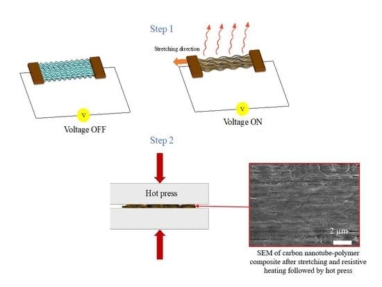
2.1. CNT Sheet Assembly

Carbon nanotube (CNT) sheets were assembled from CNT arrays produced by an ET3000 chemical vapor deposition (CVD) reactor from CVD Equipment. Prior to CNT array growth, a pulsed vapor deposition (PVD) reactor was used to deposit a thin layer of iron (Fe) and cobalt (Co) as the catalyst (thickness of 1.2 nm) on a silicon (Si) wafer coated with a 5 nm alumina (Al2O3) layer. This was then loaded into the CVD reactor to grow spinnable CNT arrays. Details about the growth conditions can be found in a previous publication by this group [28]. Ribbons from the CNT arrays were drawn and accumulated to form a 100-layer CNT sheet to be used for composites.

2.2. Polymer-CNT Composite Fabrication

Polymer-CNT composites were manufactured using a two-step approach presented in Figure 1. Polymer solutions were prepared by dissolving the polymer in N-methyl-2-pyrrolidone (NMP), forming solutions with different concentration which was achieved with an ultra-sonicator. Polymers used for this study included thermoplastic polyurethane (TPU), poly (methyl methacrylate) (PMMA) with a molecular weight of 550,000 and UltemTM 1000 (polyetherimide) (Shelton, CT, USA).
The chemical structures of these polymers are provided in Figure S1 with relevant physical properties also given in Table S1 of the supplementary information. In the first step, 5 mL of the polymer solution was introduced into the CNT sheet with a pipette. After the introduction of the solution, a voltage was applied across the sheet (along the direction of tube alignment) by a DC power source (Hewlett Packard E 3612A, Washintgon, USA), resulting in heating of the sheet by the resistive (joule) heating phenomena [29]. The voltage was increased or decreased as needed until the surface of the sheet was approximately 80 °C as registered by an infrared camera (FLIR T640, Goleta, CA, USA). Infrared (IR) images of the steps in the curing of the polymer solution are provided in Figure 2. Carbon nanotube sheets were stretched by 0.5 strain percentage with a custom stretching device shown in Figure 2 while resistive heating cured the polymer. Sheets were stretched to this particular strain percentage because our previous research showed that this was the optimal elongation for maximizing the mechanical and electrical properties of CNT sheets [30].
The evaporation of the solvent also led to further densification of the polymer-CNT composite as depicted in Figure 1a. The second stage of composite fabrication involved further curing in a tetrahedron MTP-14 hot press, Figure 1b. Samples were hot pressed at 180 °C (350 °F) for 1 h under a pressure of 9.8 MPa. The final composite was then dried in a high vacuum oven at 70 °C for 12 h. A 100 layer CNT sheet densified with only NMP was prepared as a control.

2.3. Characterization

Polymer-CNT composites and the pristine CNT sheets (serving as the control) were cut into 40 mm long and 1 mm wide strips for mechanical tests. The mechanical test samples were cut from the prepared composite and the pristine sheets with the help of an automated laser micromachining system. Ten strips were tested for each composite and the control with an Instron 5948 (Norwood, MA, USA) at a strain rate of 1 mm/s and a gauge length of 22 mm.
The sheet resistance of the composites and pristine CNTs was measured with a Jandel 4-probe instrument (Model RM3000, Kings Langley, UK). The electrical conductivity of the samples was obtained by measuring the sheet resistance in the direction parallel to CNT alignment and multiplying by the sample thickness. Thickness measurements were attained with a FEI XL30 Scanning Electron Microscope (SEM, Waltham, MA, USA). The SEM was also used for surface morphology characterizations of the composites.
Thermogravimetric analysis (TGA) was performed on the composites, to determine the mass fraction of CNTs in the composites. Thermogravimetric analysis (TGA) was done at a rate of 5 °C/min in nitrogen environment between a 60 °C to 800 °C range.
A JEOL 2100F (Peabody, MA, USA) high-resolution transmission electron microscopy (HR-TEM) was used to study the interaction between polymer and CNT’s to better understand properties of composites.

3. Results and Discussion

Polymer-CNT composites were fabricated with different concentrations of the polymer solution, namely at 0.5%, 1% and 2% wt/vol.
Figure 3 shows TGA and differential thermogravimetric (DTG) plots for PMMA, TPU and UltemTM composites at different concentrations. Thermogravimetric analysis curves for pristine CNT sheets and the pure polymer are also included for comparison.
The %wt. of CNTs in the composite was calculated using the formula below, and the results are presented in Table 1.
%   remaining   of   pristine   CNT ( ( %   loss   of   composite %   initial   loss   of   pristine   CNT %   loss   of   pure   polymer ) × 100 )
It can be seen that for pristine CNT sheets densified with only NMP, there was a mass loss of approximately 10% between 240–550 °C before stabilizing. This mass loss is attributed to the loss of NMP during the thermal process. It has been shown that NMP polymerizes when used at elevated temperatures in air [31,32]. This polymerized NMP has been revealed to lose mass in a similar range as that reported in the TGA curves (Figure 3) in a nitrogen environment [33]. A CNT sheet densified with NMP but dried in a vacuum oven instead of by resistive heating was prepared to verify this. The thermal degradation of this sample was investigated, and the results are presented in Figure S2 in the supplementary information. It can be seen that this sheet had little to no thermal degradation/mass loss thereby supporting our supposition that the NMP was polymerized by resistive heating leading to an initial mass loss. The TGA and DTG curves show that pure PMMA and TPU decomposed almost completely in the nitrogen environment, however pure UltemTM still had a residual mass of about 50% up to 800 °C, which is akin to that reported in the literature [34,35,36]. This char residue has been shown to be a result of extreme hydrogen transfer reactions and subsequent condensation reactions [37]. A reduction in polymer concentration for PMMA-CNT and UltemTM-CNT composites led to a decrease in the degradation temperature as seen in the graphs in Figure 3. This is due to an increase in thermal diffusivity in the composite caused by the addition of CNTs, which leads to a reduced composite degradation temperature [12]. However, for TPU-CNT composites, which have a two-stage degradation process, a different trend was seen. The first stage was related to the decomposition of urethane linkages and occurred around 317 °C while the second stage was the decomposition of soft segments of TPU and occurred around 376 °C [38,39]. For the first stage, an increase in CNTs (decrease in polymer concentration) led to a decrease in the degradation temperature similarly to the other polymer-CNT composites. Nonetheless, for the second stage, there was an increase in the degradation temperature as the number of CNTs increased. Similar results were reported by Liu et al. for graphene/TPU foams where the addition of graphene led to higher decomposition temperatures at the second stage [38].
The mechanical properties of various polymer-CNT composites at different polymer concentrations were also measured, and the results are presented in Table 1. The data reveals that an increase in polymer concentration led to an increase in tensile strength, with the highest at 1% wt/vol polymer concentration. Stress-strain curves of the most optimized CNT sheet composites (1% wt/vol) are presented in Figure 4. The TPU composite sample shows the highest tensile strength and the greatest strain of all the tested polymer CNT sheet composites. Stretched polymer-CNT composites fabricated with TPU and UltemTM offered the best tensile strength and load data which is attributed to the uniform polymer distribution and adhesion of the polymer on the CNT sheets as shown in Figure 5. The smooth surface texture indicates good polymer impregnation with 1% wt/vol concentration. For 2% wt/vol TPU-CNT composite, there was an improvement in the load, but since the tensile strength is based on the thickness of the samples, thicker samples led to a reduction in strength. Poly (methyl methacrylate) (PMMA)-CNT and UltemTM-CNT composites, however, gave better modulus of elasticity compared to TPU-CNT composites and this is ascribed to the difference in modulus of the starting polymers as provided in Table S1. Table 1 also shows that an increase in the polymer concentration led to a reduction in the electrical conductivity of the overall composite due to the insulating properties of these polymers, similarly to that reported in literature [40,41].
To further study the distribution of the polymer among the CNT bundles, TEM was used to analyze a single layer of sheet densified with a diluted concentration of the polymer solution (0.2% wt/vol). A lesser concentration of the polymer solution was used to easily visualize the CNTs embedded in the polymer matrix. This was compared to a single layer of CNT sheet densified with only NMP, and the results are presented in Figure 6. The densified pristine CNT web showed well aligned and tightly bundled tubes where the small gaps were bridged by CNTs. All the polymer-CNT materials revealed a similar macrostructure, with well defined, separated tubes showing little bridging. This is likely a consequence of the thin film used in sample preparation and may not be evident in thicker samples.
The micro-structure, however, should also be present in thicker samples, as it is governed by bundle-polymer and polymer-CNT interactions that are independent of the macro-structure. The CNT-PMMA tube sample had a similar microstructure to the pristine CNT one, but the tube spacing was larger. There was some visible evidence of polymer, especially along the bridging CNTs, however some of these bridging tubes were broken, perhaps due to forces present during densification and polymer consolidation. There was also no bridging between separated bundles of tubes with polymer compared to TPU-CNT and UltemTM-CNT composites. The TPU-CNT composite showed polymer incorporated into its tubes, and much larger tube spacing with some bridging. These bridges can be TPU, or TPU jacketed CNTs. The UltemTM-CNT showed the most divergent microstructure from the pristine one where the tubes were well bound, thinly coated with a polymer and with large spacing between them. The spaces were well bridged with many thin tubes and polymer, some of which crossed between bundles. Bridges consist of UltemTM alone and UltemTM-CNT. Many of these bridging tubes were under tension, suggesting a strong consolidation force during sample preparation. This accounts for the better mechanical properties of UltemTM-CNT and TPU-CNT composites compared to the one based on PMMA-CNT.

4. Conclusions

A simple process of fabricating polymer-CNT composites has been demonstrated. This method was used to make composites with different polymers, in various compositions defined by weight. Such composites were shown to improve the mechanical properties as compared to a pristine CNT sheet, accompanied with a modest decrease in the electrical conductivity. Best mechanical properties were attained at 1% wt/vol for the polymers used in this work. The best composite made with TPU and UltemTM showed significant improvement in tensile strength compared to densified and stretched CNT sheets without any polymer. This was attributed to good adhesion and interaction of the polymer with CNTs leading to improved properties.

Supplementary Materials

The following are available online at https://0-www-mdpi-com.brum.beds.ac.uk/2311-5629/5/3/35/s1, Figure S1: Typical chemical structure of: (a) PMMA; (b) TPU and (c) UltemTM 1000 thermoplastic polymers. Table S1: Relevant physical properties of different polymers used for fabricating CNT-polymer composites. Figure S2: (a) TGA and (b) DTG plots of CNT sheet densified with NMP and dried in a vacuum oven. Little or no thermal degradation was observed within the temperature range considered in this paper.

Author Contributions

S.G., N.T.A. and V.S. conceived and designed the experiments; S.G., P.K.A., D.C., M.R.H., and K.M. performed the experiments; S.G., P.K.A., D.C. and S.N.K. analyzed the data; S.G., Y.-Y.H., N.T.A., and V.S. discussed the data; S.G. and V.S. contributed reagents/materials/analysis tools.

Funding

This work was funded by the National Science Foundation (NSF) through the following grants: CMMI-0727250; SNM-1120382; ERC-0812348. The authors also appreciate the support of DURIP-ONR N00014-15-1-2473; ARMY W911NF-16-2-0026 and NASA NNX13AF46A grants.

Conflicts of Interest

The authors declare no conflicts of interest.

References

  1. Balandin, A.A. Thermal properties of graphene and nanostructured carbon materials. Nat. Mater. 2011, 10, 569–581. [Google Scholar] [CrossRef] [PubMed] [Green Version]
  2. Li, Q.; Li, Y.; Zhang, X.; Chikkannanavar, S.B.; Zhao, Y.; Dangelewicz, A.M.; Zheng, L.; Doorn, S.; Jia, Q.; Peterson, D.; et al. Structure-dependent electrical properties of carbon nanotube fibers. Adv. Mater. 2007, 19, 3358–3363. [Google Scholar] [CrossRef]
  3. Zhang, R.; Wen, Q.; Qian, W.; Su, D.S.; Zhang, Q.; Wei, F. Superstrong ultralong carbon nanotubes for mechanical energy storage. Adv. Mater. 2011, 23, 3387–3391. [Google Scholar] [CrossRef] [PubMed]
  4. Laurent, C.; Flahaut, E.; Peigney, A. The weight and density of carbon nanotubes versus the number of walls and diameter. Carbon 2010, 48, 2994–2996. [Google Scholar] [CrossRef] [Green Version]
  5. Kim, S.H.; Mulholland, G.W.; Zachariah, M.R. Density measurement of size selected multiwalled carbon nanotubes by mobility-mass characterization. Carbon 2009, 47, 1297–1302. [Google Scholar] [CrossRef]
  6. Dervishi, E.; Li, Z.; Watanabe, F.; Saini, V.; Biris, A.R.; Xu, Y.; Biris, A.S. High-aspect ratio and horizontally oriented carbon nanotubes synthesized by RF-cCVD. Diam. Relat. Mater. 2010, 19, 67–72. [Google Scholar] [CrossRef]
  7. Zhu, L.; Xu, J.; Xiu, Y.; Sun, Y.; Hess, D.W.; Wong, C.P. Growth and electrical characterization of high-aspect-ratio carbon nanotube arrays. Carbon 2006, 44, 253–258. [Google Scholar] [CrossRef]
  8. Wang, W.; Ciselli, P.; Kuznetsov, E.; Peijs, T.; Barber, A.H. Effective reinforcement in carbon nanotube-polymer composites. Philos. Trans. R. Soc. A Math. Phys. Eng. Sci. 2008, 366, 1613–1626. [Google Scholar] [CrossRef] [PubMed]
  9. Konnola, R.; Nair, C.P.R.; Joseph, K. High strength toughened epoxy nanocomposite based on poly(ether sulfone)-grafted multi-walled carbon nanotube. Polym. Adv. Technol. 2016, 27, 82–89. [Google Scholar] [CrossRef]
  10. Yang, K.; Gu, M.; Guo, Y.; Pan, X.; Mu, G. Effects of carbon nanotube functionalization on the mechanical and thermal properties of epoxy composites. Carbon 2009, 47, 1723–1737. [Google Scholar] [CrossRef]
  11. Zhou, L.; Gao, C.; Xu, W. Efficient grafting of hyperbranched polyglycerol from hydroxyl-functionalized multiwalled carbon nanotubes by surface-initiated anionic ring-opening polymerization. Macromol. Chem. Phys. 2009, 210, 1011–1018. [Google Scholar] [CrossRef]
  12. Malik, R.; Mcconnell, C.; Alvarez, N.T.; Haase, M.; Gbordzoe, S.; Shanov, V. Rapid, In Situ Plasma Functionalization of Carbon Nanotubes For Improved CNT/Epoxy Composites. RSC Adv. 2016, 6, 108840–108850. [Google Scholar] [CrossRef]
  13. Wang, X.; Yong, Z.Z.; Li, Q.W.; Bradford, P.D.; Liu, W.; Tucker, D.S.; Cai, W.; Wang, H.; Yuan, F.G.; Zhu, Y.T. Ultrastrong, Stiff and Multifunctional Carbon Nanotube Composites. Mater. Res. Lett. 2013, 1, 19–25. [Google Scholar] [CrossRef]
  14. Andrews, R.; Weisenberger, M.C. Carbon nanotube polymer composites. Curr. Opin. Solid State Mater. Sci. 2004, 8, 31–37. [Google Scholar] [CrossRef]
  15. Safadi, B.; Andrews, R.; Grulke, E.A. Multiwalled carbon nanotube polymer composites: Synthesis and characterization of thin films. J. Appl. Polym. Sci. 2002, 84, 2660–2669. [Google Scholar] [CrossRef]
  16. Claes, M.; Bonduel, D.; Pegel, S.; Alexandre, M.; Poetschke, P.; Dubois, P.; Luizi, F. New route to manufacture high performance carbon nanotubes nanocomposites based on pre-dispersed concentrates generated by in-situ polymerisation. In Technical Proceedings of the 2006 NSTI Nanotechnology Conference and Trade Show; ICCN: Lope Haydenville, MA, USA, 2006; pp. 218–221. [Google Scholar]
  17. Spitalsky, Z.; Tasis, D.; Papagelis, K.; Galiotis, C. Carbon nanotube-polymer composites: Chemistry, processing, mechanical and electrical properties. Prog. Polym. Sci. 2010, 35, 357–401. [Google Scholar] [CrossRef]
  18. Chien, A.T.; Cho, S.; Joshi, Y.; Kumar, S. Electrical conductivity and Joule heating of polyacrylonitrile/carbon nanotube composite fibers. Polym 2014, 55, 6896–6905. [Google Scholar] [CrossRef]
  19. Kim, J.W.; Sauti, G.; Siochi, E.J.; Smith, J.G.; Wincheski, R.A.; Cano, R.J.; Connell, W.J.; Wise, K.E. Toward high performance thermoset/carbon nanotube sheet nanocomposites via resistive heating assisted infiltration and cure. ACS Appl. Mater. Interfaces 2014, 6, 18832–18843. [Google Scholar] [CrossRef]
  20. Nam, T.H.; Goto, K.; Yamaguchi, Y.; Premalal, E.V.A.; Shimamura, Y.; Inoue, Y.; Naito, K.; Ogihara, S. Effects of CNT diameter on mechanical properties of aligned CNT sheets and composites. Compos. Part A Appl. Sci. Manuf. 2015, 76, 289–298. [Google Scholar] [CrossRef] [Green Version]
  21. Nam, T.H.; Goto, K.; Yamaguchi, Y.; Premalal, E.V.A.; Shimamura, Y.; Inoue, Y.; Naito, K.; Ogihara, S. Improving mechanical properties of high volume fraction aligned multi-walled carbon nanotube/epoxy composites by stretching and pressing. Compos. Part B Eng. 2016, 85, 15–23. [Google Scholar] [CrossRef] [Green Version]
  22. Nam, T.H.; Goto, K.; Yamaguchi, Y.; Premalal, E.V.A.; Shimamura, Y.; Inoue, Y.; Naito, K.; Ogihara, S. Mechanical property enhancement of aligned multi-walled carbon nanotube sheets and composites through press-drawing process. Adv. Compos. Mater. 2016, 25, 73–86. [Google Scholar] [CrossRef]
  23. Huu, T.; Goto, K.; Nakayama, H.; Oshima, K.; Premalal, V.; Shimamura, Y.; Inoue, Y.; Naito, K.; Kobayashi, S. Composites: Part A Effects of stretching on mechanical properties of aligned multi-walled carbon nanotube/epoxy composites. Compos. Part A 2014, 64, 194–202. [Google Scholar] [CrossRef]
  24. Cheng, Q.; Bao, J.; Park, J.; Liang, Z.; Zhang, C.; Wang, B. High Mechanical Performance Composite Conductor: Multi-Walled Carbon Nanotube Sheet/Bismaleimide Nanocomposites. Adv. Funct. Mater. 2009, 19, 3219–3225. [Google Scholar] [CrossRef]
  25. Zhang, L.; Wang, X.; Li, R.; Li, Q.; Bradford, P.D.; Zhu, Y. Microcombing enables high-performance carbon nanotube composites. Compos. Sci. Technol. 2016, 123, 92–98. [Google Scholar] [CrossRef]
  26. Martin, C.A.; Sandler, J.K.W.; Windle, A.H.; Schwarz, M.K.; Bauhofer, W.; Schulte, K.; Shaffer, M.S.P. Electric field-induced aligned multi-wall carbon nanotube networks in epoxy composites. Polymer 2005, 46, 877–886. [Google Scholar] [CrossRef]
  27. Moaseri, E.; Karimi, M.; Baniadam, M.; Maghrebi, M. Improvements in mechanical properties of multi-walled carbon nanotube-reinforced epoxy composites through novel magnetic-assisted method for alignment of carbon nanotubes. Compos. Part A Appl. Sci. Manuf. 2014, 64, 228–233. [Google Scholar] [CrossRef]
  28. Alvarez, N.T.; Miller, P.; Haase, M.; Kienzle, N.; Zhang, L.; Schulz, M.J.; Shanov, V. Carbon Nanotube Assembly at Near-industrial Natural-fiber Spinning Rates. Carbon 2015, 86, 350–357. [Google Scholar] [CrossRef]
  29. Gbordzoe, S.; Malik, R.; Alvarez, N.; Wolf, R.; Shanov, V. Flexible Low-Voltage Carbon Nanotube Heaters and their Applications. In Advances in Carbon Nanostructures; Intech: London, UK, 2016; pp. 123–136. [Google Scholar]
  30. Gbordzoe, S.; Yarmolenko, S.; Hsieh, Y.Y.; Adusei, P.K.; Alvarez, N.T.; Fialkova, S.; Shanov, V. Three-dimensional texture analysis of aligned carbon nanotube structures. Carbon 2017, 121, 591–601. [Google Scholar] [CrossRef]
  31. Berrueco, C.; Alvarez, P.; Venditti, S.; Morgan, T.J.; Herod, A.A.; Millan, M.; Kandiyoti, R. Sample contamination with NMP-oxidation products and byproduct-free NMP removal from sample solutions. Energy Fuels 2009, 23, 3008–3015. [Google Scholar] [CrossRef]
  32. Cai, M.F.; Smart, R.B. Quantitative Analysis of N-Methyl-2-pyrrolidinone in Coal Extracts by TGA-FTIR. Energy Fuels 1993, 7, 52–56. [Google Scholar] [CrossRef]
  33. Carey, B.J.; Daeneke, T.; Nguyen, E.P.; Wang, Y.; Ou, J.Z.; Zhuiykov, S.; Kalantar-Zadeh, K. Two solvent grinding sonication method for the synthesis of two-dimensional tungsten disulphide flakes. Chem. Commun. 2015, 51, 3770–3773. [Google Scholar] [CrossRef] [PubMed]
  34. Abbasi, H.; Antunes, M.; Velasco, J.I. Graphene nanoplatelets-reinforced polyetherimide foams prepared by water vapor-induced phase separation. Express Polym. Lett. 2015, 9, 412–423. [Google Scholar] [CrossRef]
  35. Zhu, H.; Jie, X.; Wang, L.; Kang, G.; Liu, D.; Cao, Y. Effect of MIL-53 on phase inversion and gas separation performance of mixed matrix hollow fiber membranes. RSC Adv. 2016, 6, 69124–69134. [Google Scholar] [CrossRef]
  36. Mao, H.; Zhang, S. Synthesis, characterization and gas transport properties of novel poly(amine-imide)s containing tetraphenylmethane pendant groups. J. Mater. Chem. A 2014, 2, 9835–9843. [Google Scholar] [CrossRef]
  37. Carroccio, S.; Puglisi, C.; Montaudo, G. Thermal degradation mechanisms of polyetherimide investigated by direct pyrolysis mass spectrometry. Macromol. Chem. Phys. 1999, 200, 2345–2355. [Google Scholar] [CrossRef]
  38. Liu, H.; Dong, M.; Huang, W.; Gao, J.; Dai, K.; Guo, J.; Zheng, G.; Liu, C.; Shena, C.; Guo, Z. Lightweight conductive graphene/thermoplastic polyurethane foams with ultrahigh compressibility for piezoresistive sensing. J. Mater. Chem. C 2017, 5, 73–83. [Google Scholar] [CrossRef]
  39. Marini, J.; Pollet, E.; Averous, L.; Bretas, R.E.S. Elaboration and properties of novel biobased nanocomposites with halloysite nanotubes and thermoplastic polyurethane from dimerized fatty acids. Polym 2014, 55, 5226–5234. [Google Scholar] [CrossRef]
  40. Lekawa-Raus, A.; Patmore, J.; Kurzepa, L.; Bulmer, J.; Koziol, K. Electrical properties of carbon nanotube based fibers and their future use in electrical wiring. Adv. Funct. Mater. 2014, 24, 3661–3682. [Google Scholar] [CrossRef]
  41. Vigolo, B.; Vigolo, B.; Pe, A.; Coulon, C. Macroscopic Fibers and Ribbons of Oriented Carbon Nanotubes. Science 2000, 290, 1331–1334. [Google Scholar] [CrossRef]
Figure 1. Schematic illustration of a two-step process for fabricating polymer-carbon nanotube (CNT) composites. (a) Step 1 shows the experimental setup of the fabrication of polymer-CNT composite, while (b) Step 2 shows the final composite manufacturing process where the composite is cured in a hot press under vacuum.
Carbon 05 00035 g001
Figure 2. (a) CNT sheet connected to copper electrodes on a custom stretching device. Infrared (IR) images of (b) a pristine CNT sheet, (c) CNT sheet after introduction of polymer in N-methyl-2-pyrrolidone (NMP), (d) CNT sheet during initial heating and infiltration of polymer and (e) CNT sheet after polymer cured.
Carbon 05 00035 g002
Figure 3. Graphs showing thermogravimetric analysis (TGA) and differential thermogravimetric (DTG) plots for (a,b) poly (methyl methacrylate) (PMMA)-CNT, (c,d) thermoplastic polyurethane (TPU)-CNT and (e,f) UltemTM-CNT composites at different concentrations. Experiments were performed in a nitrogen environment with an alumina crucible at a heating rate of 5 °C/min.
Carbon 05 00035 g003
Figure 4. Stress vs. strain curves of the made CNT polymer composite sheets including Pristine, PMMA 1%, TPU 1% and Ultem 1% samples, respectively.
Carbon 05 00035 g004
Figure 5. Scanning electron microscope images of PMMA-CNT composites at (a) 0.5%, (b) 1% and (c) 2% wt/vol concentration, TPU-CNT composites at (d) 0.5%, (e) 1% and (f) 2% wt/vol concentration and UltemTM-CNT composites at (g) 0.5%, (h) 1% and (i) 2% wt/vol concentration.
Carbon 05 00035 g005
Figure 6. Transmission electron microscopy (TEM) images of carbon nanotube (CNT) and polymer-CNT composites. (a) Single-layer CNT web densified with NMP, (b) single-layer CNT web composited with PMMA, (c) single-layer CNT web composited with TPU, and (d) single-layer CNT web composited with UltemTM.
Carbon 05 00035 g006
Table 1. Physical properties of polymer-CNT composites at different CNT concentrations.
SampleThickness (µm)Tensile Strength (MPa)Load (N)Modulus (GPa)Conductivity (S/cm)Weight Percent of CNT
Pristine 4.89461 ± 242.15 ± 0.2038 ± 5151 ± 9100
PMMA 0.5%4.82545 ± 1002.49 ± 0.4658 ± 7156 ± 2362
PMMA 1%5.16652 ± 763.20 ± 0.3759 ± 8129 ± 355
PMMA 2%6.1534 ± 803.04 ± 0.4653 ± 4107 ± 352
TPU 0.5%4.25717 ± 872.90 ± 0.3553 ± 6180 ± 1267
TPU 1%4.40858 ± 873.57 ± 0.3648 ± 6150 ± 557
TPU 2%4.82814 ± 1293.71 ± 0.5940 ± 6137 ± 550
UltemTM 0.5%4.18671 ± 862.74 ± 0.4959 ± 3127 ± 364
UltemTM 1%4.23815 ± 1243.28 ± 0.572 ± 6139 ± 254
UltemTM 2%5.19631 ± 1193.11 ± 0.5968 ± 9120 ± 1550

