
Increased Electrical Conductivity of Carbon Nanotube Fibers by Thermal and Voltage Annealing
by
 , , and
Varun Shenoy Gangoli
1,2,* ,
,
Chris J. Barnett
3,*,
James D. McGettrick
4,
Alvin Orbaek White
1 and
and
Andrew R. Barron
1,2,5,6,7,* 1
Energy Safety Research Institute, Bay Campus, Swansea University, Swansea SA1 8EN, UK
2
Department of Chemistry, Rice University, Houston, TX 77005, USA
3
Department of Physics, Singleton Campus, Swansea University, Swansea SA2 8PP, UK
4
SPECIFIC, Bay Campus, Swansea University, Swansea SA1 8EN, UK
5
Arizona Institutes for Resilience (AIR), University of Arizona, Tucson, AZ 85721, USA
6
Department of Materials Science and Nanoengineering, Rice University, Houston, TX 77005, USA
7
Faculty of Engineering, Universiti Teknologi Brunei, Jalan Tungku Link, Gadong BE1410, Brunei
*
Authors to whom correspondence should be addressed.
C 2022, 8(1), 1; https://0-doi-org.brum.beds.ac.uk/10.3390/c8010001
Submission received: 6 November 2021
/
Revised: 12 December 2021
/
Accepted: 20 December 2021
/
Published: 23 December 2021
(This article belongs to the Collection Nanocarbon-Based Composites and Their Thermal, Electrical, and Mechanical Properties)
Abstract
:We report the effect of annealing, both electrical and by applied voltage, on the electrical conductivity of fibers spun from carbon nanotubes (CNTs). Commercial CNT fibers were used as part of a larger goal to better understand the factors that go into making a better electrical conductor from CNT fibers. A study of thermal annealing in a vacuum up to 800 °C was performed on smaller fiber sections along with a separate analysis of voltage annealing up to 7 VDC; both exhibited a sweet spot in the process as determined by a combination of a two-point probe measurement with a nanoprobe, resonant Raman spectroscopy, and X-ray photoelectron spectroscopy (XPS). Scaled-up tests were then performed in order to translate these results into bulk samples inside a tube furnace, with similar results that indicate the potential for an optimized method of achieving a better conductor sample made from CNT fibers. The results also help to determine the surface effects that need to be overcome in order to achieve this.
1. Introduction
Carbon nanotubes (CNTs) have been the subject of many research groups worldwide for nearly three decades now, and their untapped potential is still the subject of newly published articles daily. This is not to say that CNTs have never made it out of the lab, and in fact there are several different applications that are in use already in industries ranging from energy, manufacturing, construction, sports, transportation, and even as art [1,2,3,4]. One challenge left unconquered is the replacement of the use of metal, especially aluminum and copper, for electricity transmission. The electric grid varies in material composition from region to region; however, in order to achieve a compromise of weight and electrical conductivity, it tends to consist of an alloy of the two metals more often than not [5]. A compromise it remains, too, given that the weight of copper offsets the practical benefits of its use in long transmission lines, and thermal resistance losses add up in underground cable installations.
CNT-based cables could be a viable alternative, since their electrical conductivity exceeds that of copper while weighing very little, owing to the hollow nature of individual nanotubes [5]. There have been many attempts at this, including spinning out long individual CNT fibers, drawing and extruding acid-doped CNT fibers [6], and even composite fibers of CNTs and the aforementioned copper [7,8,9,10]. The latter approach, when not completely made in-house, involves the use of commercial CNT fibers that are often inconsistent when it comes to the uniformity of their physical and chemical properties, which in turn makes them harder to use as a control starting material that is then further optimized for increased electrical conductivity.
One of the approaches used to circumvent this issue with commercially available CNT fibers, and indeed most CNT sources as a whole, is to purify them and remove the impurities, including any residual catalyst and amorphous carbon [11]. Depending on the manufacturing process, this can be a bulk phenomenon or one with a substantial surface-only effect. CNT fibers, when used for electrical transmission, can have different conduction pathways depending on the paths of least available resistance, and the point of contact at the surface of the fibers is a critical step to be accounted for [12,13,14].
There is a strong need to better understand the contact resistances, and to take steps to address this by purification at the local surface sites. The work described herein was aimed at addressing both points and describes two routes of achieving the same end goal of increased electrical conductivity as a result of lowered contact resistance between the electric probes and the CNT fibers. This study made use of the of thermal and voltage annealing processes with the two-point probe measurements that were also supported by the characterization of spot points, in order to reveal the change in the chemical composition following the annealing. The small-scale experiments were then scaled up on a macro-scale to demonstrate a proof-of-concept for quickly achieving a uniform, more optimized CNT fiber for electrical conductivity applications. Unlike the purification processes that are well known [11], our approach relies on internal electrical heating and not a mixture of chemical treatment and heat. We believe this makes the results described herein a unique methodology.
2. Experimental Section
2.1. Materials
A 100 m yarn of YE-A10 carbon nanotube (CNT) fiber was purchased from Nanocomp Technologies, Inc. (New Hampshire, NH, USA) and handled as previously described [15]. This was a single-ply fiber of single- and few-walled CNTs with a rated average diameter of 130 µm. Several 1 cm-long and 30 cm-long pieces were cut for the experiments as described below.
2.2. Nanoprobe Measurements
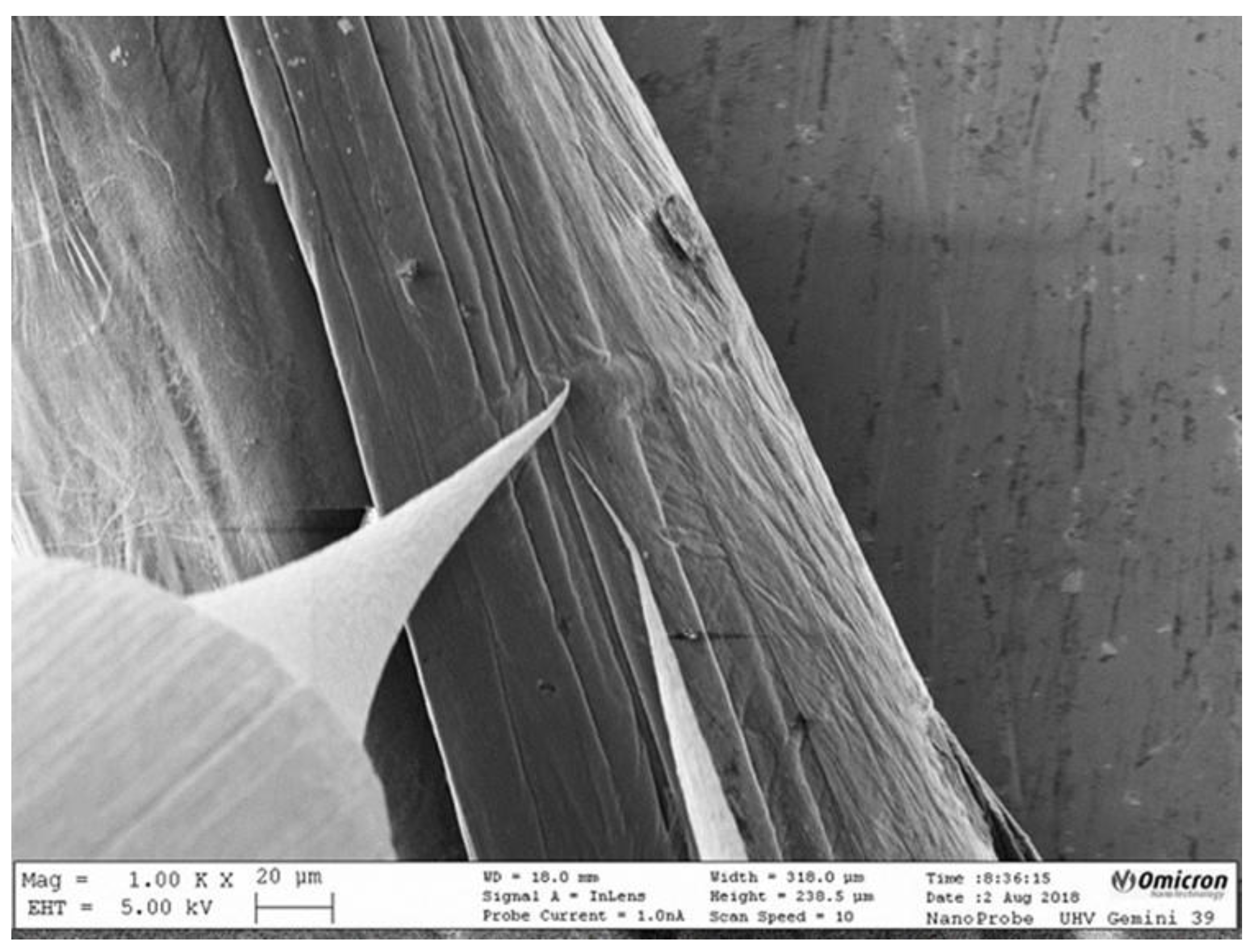
A 1 cm-long piece of the CNT fiber was loaded into an Omicron LT nanoprobe (now part of Scienta Omicron, Uppsala, Sweden) equipped with an SEM column (base pressure 1 × 10⁻¹⁰ mbar). Tungsten tips were etched in a 2 M KOH solution and, to ensure that the native probe oxide did not affect the measurements, the tungsten probes were direct-current annealed in the nanoprobe using the method described in [16,17]. The probes were then lowered onto the fiber using the method described in [12,13,18], to ensure the probe pressure did not induce strain in the sample or affect the measured I-V, as well as to ensure consistent measurements, and positioned 20 μm apart using the SEM images, an example of which is shown in Figure 1. I-V measurements between −1 V and +1 V were taken at eight locations on the fiber, and five repeat measurements were taken at each location for statistical accuracy. During the voltage sweeps, the SEM beam was switched off, as it is known that the beam can affect I-V measurements. The I-V measurements here were taken at 25 °C, and this served as a reference sample to use in subsequent experiments.
2.3. Thermal Annealing in Nanoprobe
A 1 cm-long piece of the Nanocomp YE-A10 CNT fiber was loaded into the nanoprobe’s annealing stage and thermally annealed for an hour at 100 °C. The temperature was calculated using the PN heater calibration curve provided by Omicron [12,13]. The fiber was then allowed to cool to 25 °C and then I-V measurements were taken using the same procedure as described above. This piece was then removed from the nanoprobe and marked for subsequent characterization. A separate 1 cm piece of the fiber was treated in the same way, except it was heated to 200 °C. Six more such pieces were used to complete a thermal-analysis study from 100–800 °C in increments of 100 °C, in addition to the reference sample from earlier that was probed at 25 °C without any annealing.
2.4. Voltage Annealing in Nanoprobe
A 1 cm-long piece of the CNT fiber was loaded into the nanoprobe’s stage and I-V measurements between −2 V and +2 V were taken at eight locations on the fiber, and then five repeat measurements were taken at each location for statistical accuracy. The sample was then removed from the nanoprobe and marked for subsequent characterization. Five more such samples were used, so there was a total of seven samples that were probed from ±1 V to ±7 V, including the reference sample from earlier. The tungsten tips were found to be welded onto the fiber surface at ±8 V, indicating the point of no return under these particular testing conditions.
2.5. Thermal Annealing in Tube Furnace
A 30 cm-long piece of the CNT fiber was placed in a quartz tube with a 1” outer diameter and enclosed inside a vacuum-furnace tube system that uses a Thermo Scientific 54500 (Massachusetts, MA, USA) high-temperature tube furnace. The quartz tube was then pumped down to a vacuum of 9 × 10⁻³ mbar, followed by thermal annealing at temperatures ranging from 100 °C to 800 °C in 100 °C increments for 1 h. After annealing, the fibers were allowed to cool to room temperature in the vacuum before being removed, and then I-V measurements were taken for a 1 cm section of each fiber between −1 V and +1 V to allow for a direct comparison with the set of samples that were thermally annealed in the nanoprobe itself.
2.6. Characterization
In addition to the I-V measurements in the nanoprobe that helped to generate an average electrical resistance for each sample, resonant Raman spectra were also collected for each sample. These were taken using a Renishaw inVia™ Raman microscope (Wotton-under-Edge, UK) equipped with a 785 nm laser and a Leica PL Fluortar L50x/0.55 long-working-distance objective lens. The Raman laser-excitation powers were determined by increasing the laser irradiance until a spectral transition from baseline noise to a weak signal-to-noise ratio of ~3 at a Raman shift of 1600 cm−1 was observed. The actual irradiances are unknown, and not relevant to this discussion. This resulted in a relatively flat background for the 785 nm spectra, with 785 nm chosen to resonate with the majority of the fiber samples as opposed to the other available lasers (633 and 514 nm). The collection times were chosen in order to acquire >25,000 cts at 1600 cm−1, and a minimum of five separate Raman spectrum maps were collected per sample for statistical accuracy. A thermogravimetric analysis was performed on the sample that was thermally annealed in the tube furnace using a TA Instrument SDT Q600 (Delaware, DE, USA), and the samples were run in an open alumina crucible under a continuous air flow of 100 mL/min with a heating ramp rate of 10 °C/min. The samples that were thermally annealed in the tube furnace also had enough material remaining for characterization in a Kratos Axis Supra XPS (Manchester, UK) at a base pressure of ~1 × 10⁻⁹ bar. The fibers were mounted free-standing over the relatively large (cm scale) holes on the sample bar to remove any risk of substrate influence on the final data, with each point at least 2 mm apart. The conductive fibers were mounted in an electrical connection with the ground. As such, the charge neutralizer was not used, and no charge correction was applied to the data. A minimum of three X-ray photoelectron spectroscopy (XPS) spectra were collected per fiber sample and analyzed for statistical accuracy using CasaXPS (Version 2.3.23rev1.1K).
3. Results and Discussion
3.1. Thermal Annealing in Nanoprobe
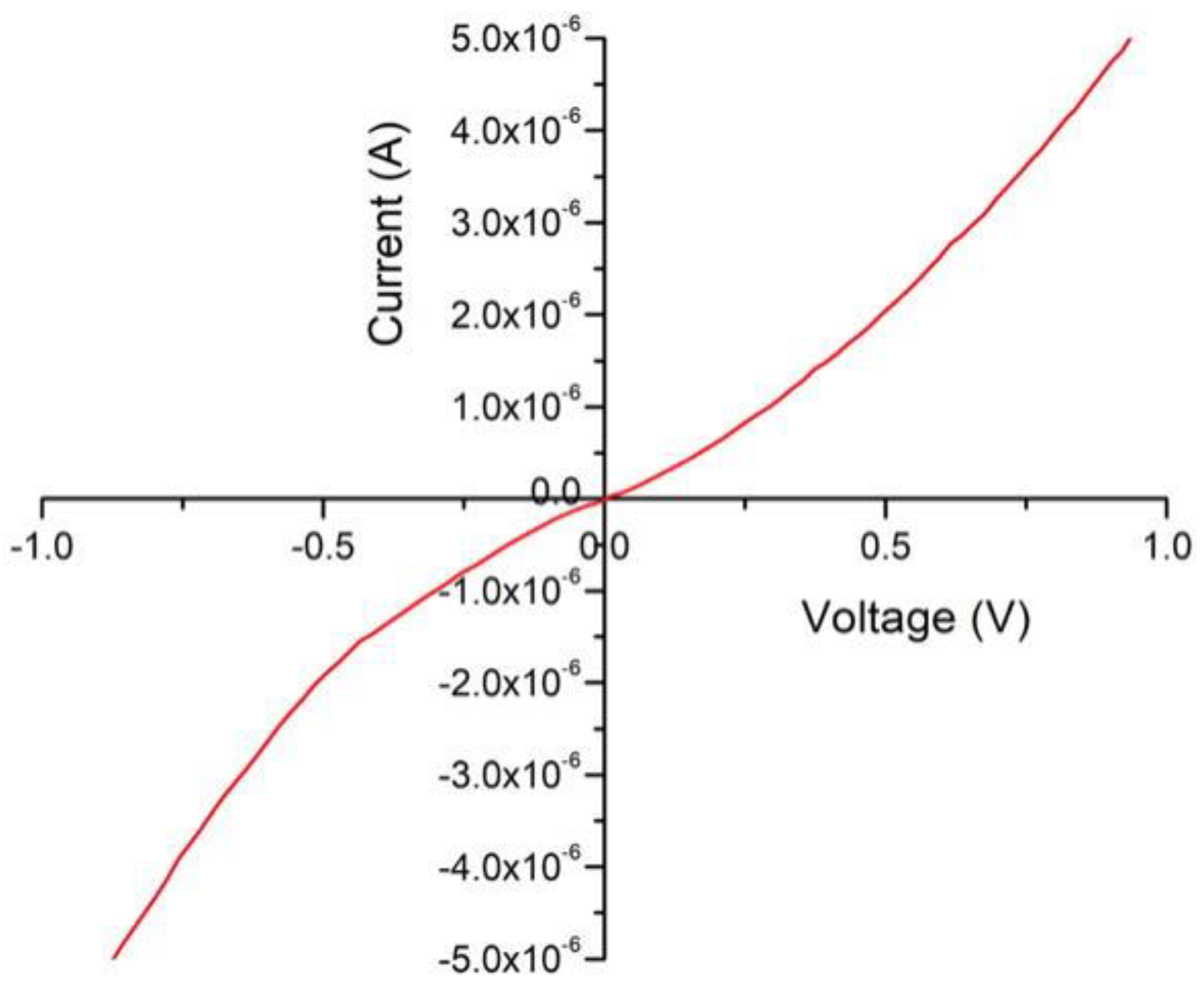
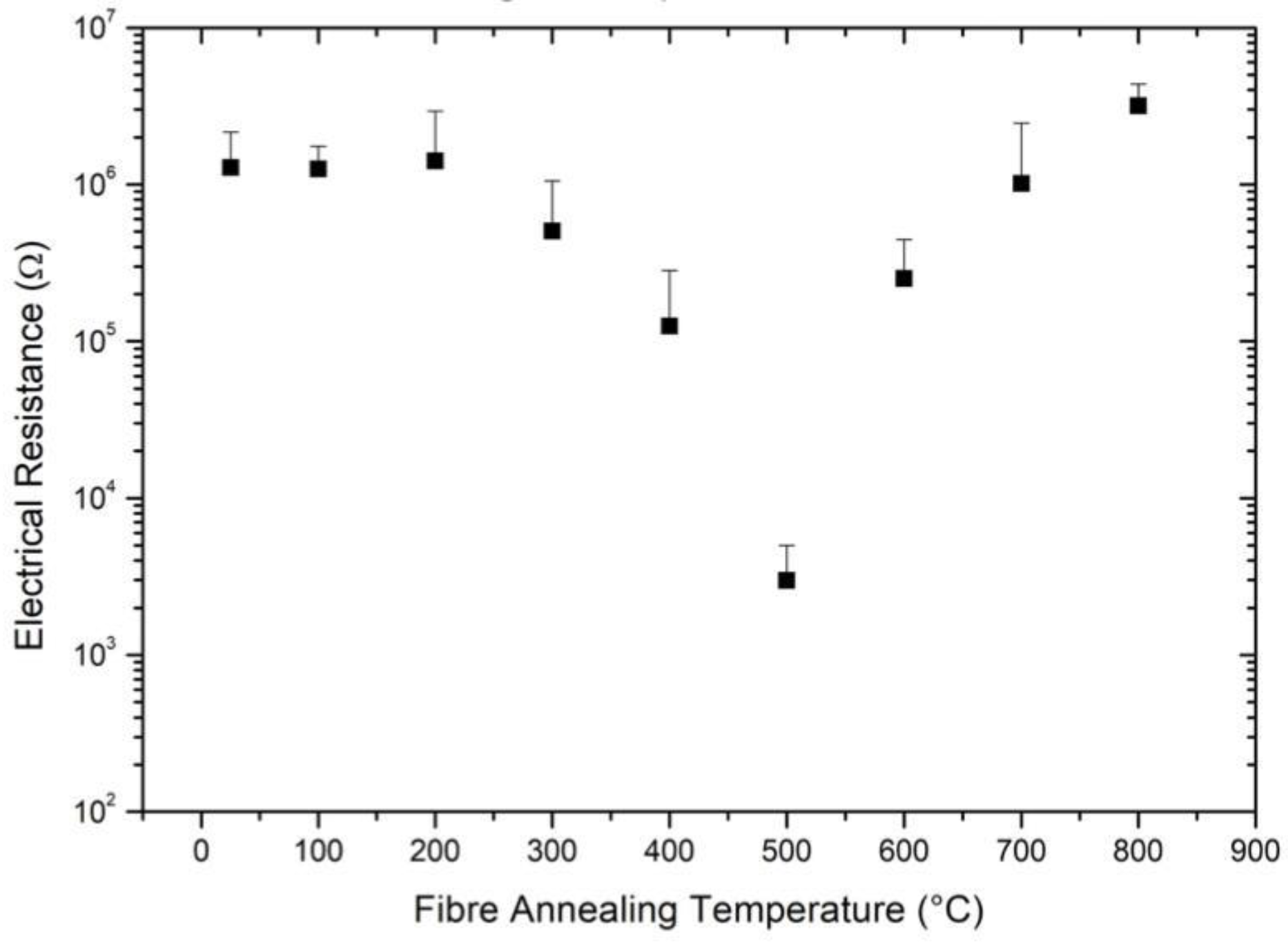
Figure 1 illustrates the reference experiment of an I-V measurement of Nanocomp’s YE-A10 CNT fiber (as-is) in the nanoprobe. This involved the use of two tungsten probes that were separated by 20 µm and in contact with the fiber surface, with a voltage sweep from −1 V to +1 V. The current, in amps, was measured at each collected datapoint and plotted as a function of the voltage. One such measurement curve is seen in Figure 2, and each set had 100 datapoints. The electrical resistance was calculated at each point and the same process was repeated for all other such acquisitions at different locations along the CNT fiber surface. This resulted in a lot of data that were used to calculate the reported average electrical resistance and the associated standard deviation for statistical accuracy. These are plotted in Figure 3 for the reference sample measured at 25 °C, along with the subsequent samples generated after thermal annealing under vacuum in the nanoprobe, with annealing temperatures ranging from 100 °C to 800 °C in steps of 100 °C.
Figure 3 is a semi-log plot owing to the multiple orders of magnitude of the change in electrical resistance, with a starting value of 1.28 × 10⁶ Ω, which then remains nearly the same until an annealing temperature of 300 °C, following which it continually decreases with annealing temperature down to a minimum average of 2.98 × 10³ Ω at 500 °C, resulting in a three-orders-of-magnitude reduction in electrical resistance under these testing conditions. The electrical resistance then increases in a manner that reverses the trend, going higher than the starting value and reaching 3.17 × 10⁶ Ω at 800 °C. The trend here was strong enough not to merit further study of the annealing conditions past 800 °C. The data, while confirming a sweet spot for minimum electrical resistance for these CNT fibers at an annealing temperature of 500 °C, also show an irreversible performance drop in electrical conductivity with increased annealing temperature. Both of these observations necessitated further investigations.
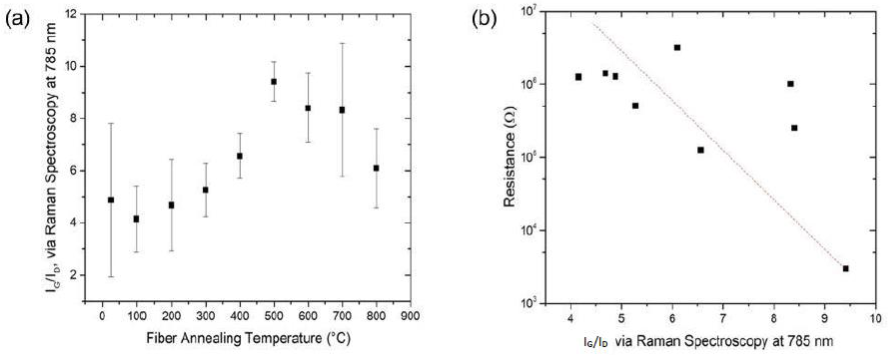
Given the limited size of the samples (1 cm in length), there was not sufficient material to perform macroscopic analysis, which prompted the scale-up study discussed below; however, resonant Raman microscopy can help to determine any relative change in the quality of the carbon [19,20,21] in the CNT fibers as a function of the thermal-annealing temperatures in the nanoprobe. Figure 4a shows the average ratio of the intensity of the G- and D-peaks in the spectra collected for each sample, with IG helping to quantify the amount of graphitic carbon in the sample, which in this case is sp2-hybridized carbon in the form of graphene and the CNTs themselves. ID, in contrast, is predominantly a measure of sp3-hybridized carbon; it is attributed to the content of amorphous carbon that is present in the CNT fibers and has a higher electrical resistance relative to CNTs [22]. Indeed, TEM imaging previously performed on analogous Nanocomp CNT fibers revealed interspersed amorphous carbon [23], although the conclusions drawn from this work are hard to justify given the physical changes to the individual CNTs as part of the TEM sample preparation.
The relative content of CNTs to amorphous carbon impurities remained essentially constant with annealing temperature up to 300 °C, followed by a definite increase up to a maximum point with the sample annealed at 500 °C, and then it decreased again, although not down to the starting value. The plot in Figure 4a essentially mirrors that in Figure 3, suggesting that the electrical resistance is related to the average IG/ID ratio. As seen in Figure 4b, there is generally a downward trend as expected from the two separate trends with annealing temperature. To explain the observed changes with annealing temperature, we hypothesize that with increasing annealing temperature there is removal of amorphous carbon, along with the potential self-repair of graphene and CNTs. Above 600 °C there is both the possibility of the removal of CNTs and of physical damage and disruptions to the CNT conduction pathways themselves [24]. The increased standard deviation at higher temperatures, combined with a decrease in the Raman spectra signal-to-noise ratio, add credence to the loss of materials remaining to resonate at the energy supplied by the 785 nm excitation laser.
3.2. Voltage Annealing in Nanoprobe
Previously reported results have shown an analogous effect of applied voltage on CNTs and CNT fibers compared to thermal annealing, so much so that the former can itself be seen as voltage annealing [12]. This was the drive behind these experiments, wherein 1 cm-long CNT-fiber samples were probed in the nanoprobe as before, except without any thermal annealing and instead using voltage sweeps from ±1 V to ±8 V. This meant that the sample swept from a specific voltage, e.g., ±7 V, only underwent I-V measurements with applied voltage ranging from −7 V to +7 V, rather than seven separate scans from ±1 V, ±2 V, all the way to ±7 V. This decoupled voltage annealing helps to remove any layer-by-layer treatment effects that would otherwise have been possible with the stepwise approach but is more applicable to the investigation of the effect of annealing voltage over electrical resistance, especially when it comes to replicating these results with different samples and sample sizes alike.
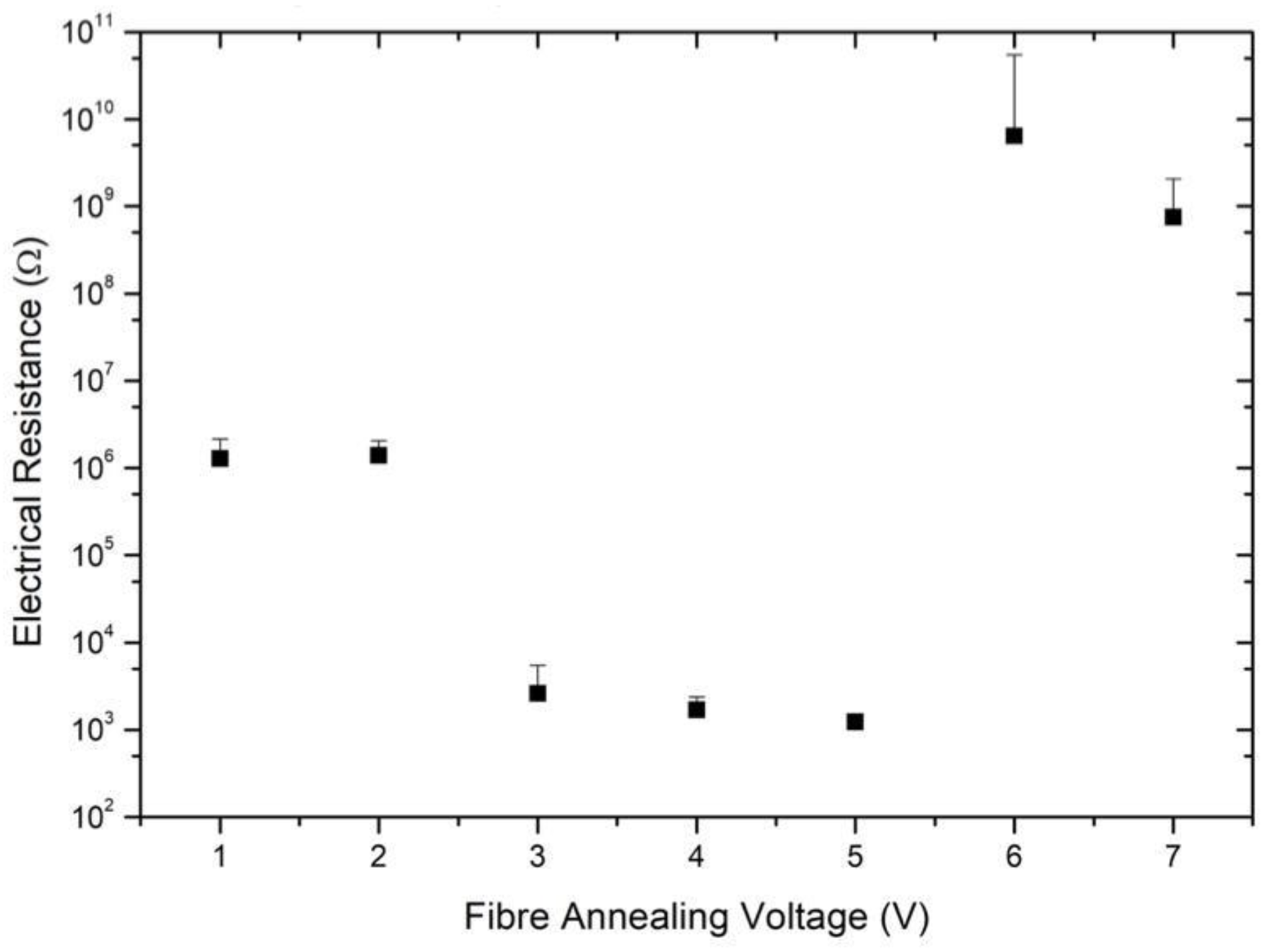
Figure 5 shows the reference sample measured at 25 °C and with the voltage sweep from −1 V to +1 V. This remains within the error margins for the sample swept between −2 V and +2 V, but then there is a significant drop at ±3 V with an average electrical resistance of 2.63 × 10³ Ω, which is another three-orders-of-magnitude reduction as was observed with thermal annealing. The decrease continues through ±5 V, albeit with a slower rate of decrease, and reaches a minimum value of 1.24 × 10³ Ω. There is then a relatively massive jump in resistance immediately afterwards, resulting in an irreversible degradation of those specific samples in terms of their electrical conduction pathways. This consistently occurred during these voltage sweeps, and thus the findings are statistically accurate as well.
A similar hypothesis is postulated here, wherein a voltage threshold is required to lower the contact resistance between the probes and the CNT fiber, with the impurities being removed first followed by damage to the conduction pathways as voltage increases.
3.3. Thermal Annealing in Tube Furnace
The experiments until this point involved short CNT-fiber sections, and further characterization would have benefited from scaling up the annealing experiments. Voltage annealing is less trivial to perform with larger sections of fibers, especially given the easier access to tube furnaces of various sizes. Multiple 30 cm-long sections were thus annealed in a tube furnace as described in the methodology section, with annealing temperatures set to match those of the inside of the nanoprobe itself. The operating pressure in the tube furnace was read as 9 × 10⁻³ mbar, although here the limitation was more the pressure gauge itself, and the actual pressure was likely lower. Since this was not as low a pressure as in the nanoprobe, it was accordingly expected that the annealing effect may be different at different temperatures.
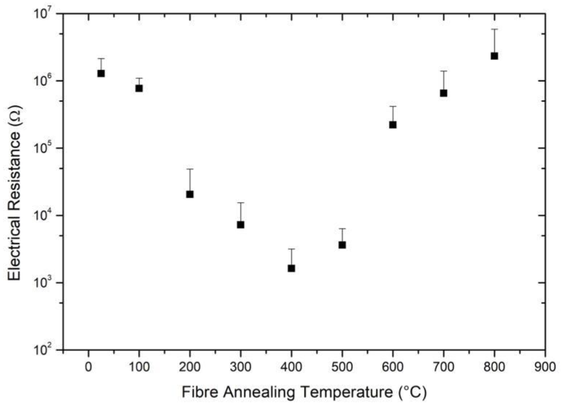
Figure 6 shows the average electrical resistance of the annealed fibers, as measured by the nanoprobe, as a function of the thermal-annealing temperature in the tube furnace. As with the thermal annealing of the microscopic samples (Figure 3), the data for the macroscopic samples (Figure 6) show an initial decrease in resistance (from the reference sample with 1.28 × 10⁶ Ω at 25 °C) with the increased annealing temperature down to 1.63 × 10³ Ω at 400 °C. Above this temperature there is a slight increase to 3.63 × 10³ Ω at 500 °C before the electrical resistance increases more dramatically at higher temperatures. It could be that the actual sweet spot in both thermal-annealing experiments is somewhere between 400–500 °C, but the practical benefits of finer tuning are outweighed by the net improvements already achieved. It should be noted that the two heating systems (controllers and associated temperature measurement) may also cause a difference in the actual temperature versus the indicated temperatures that may be responsible for this offset.
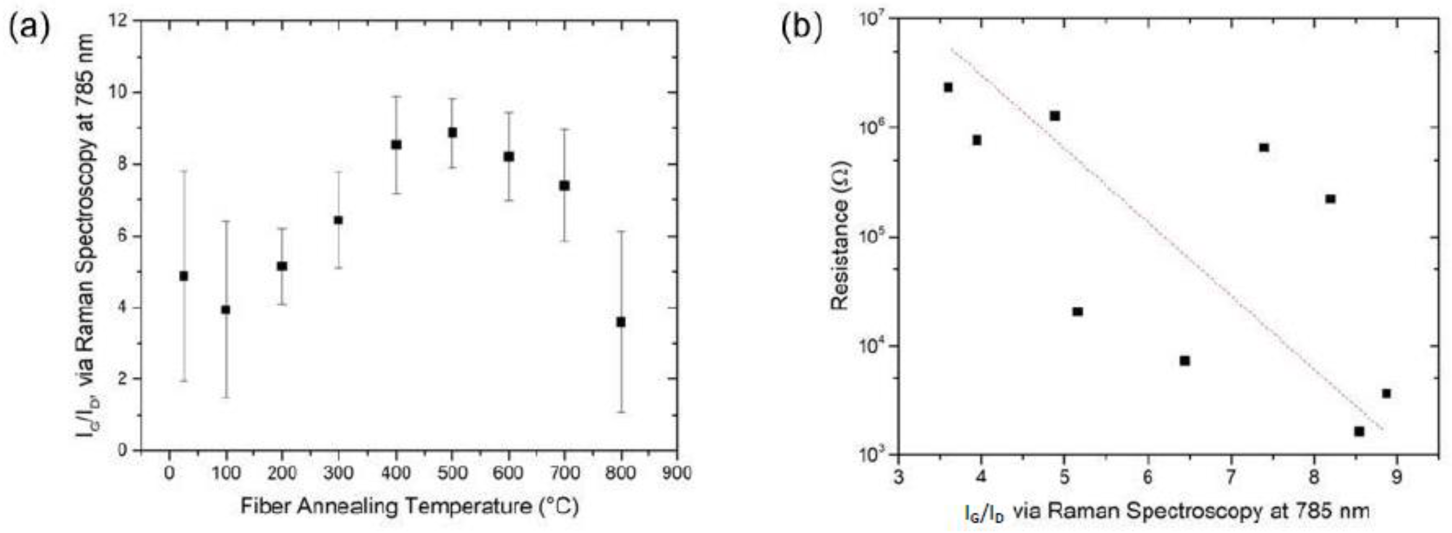
As with the thermal-annealing experiments in the nanoprobe itself, the resonant Raman spectroscopy of the longer CNT-fiber samples that were annealed in a tube furnace shows in Figure 7a the relative content of CNTs to amorphous carbon impurities increasing with annealing temperature, reaching a maximum when the samples were annealed at 400 and 500 °C, and then decreasing again. Once again, this can be hypothesized as a process that begins with the removal of amorphous carbon and is then followed by the removal of CNTs as the annealing temperature continues to increase past 600 °C. The higher standard deviations here can be attributed to the tube furnace not having as uniform a heating field throughout the length of the fiber inside, and this could have also contributed to the slight discrepancy in the comparison of the annealing sweet spot in the nanoprobe. Figure 7b again relates the change in electrical resistance of the fiber sections to the corresponding average IG/ID values, and there is once more a downward trend as expected from the two separate trends of annealing temperature.
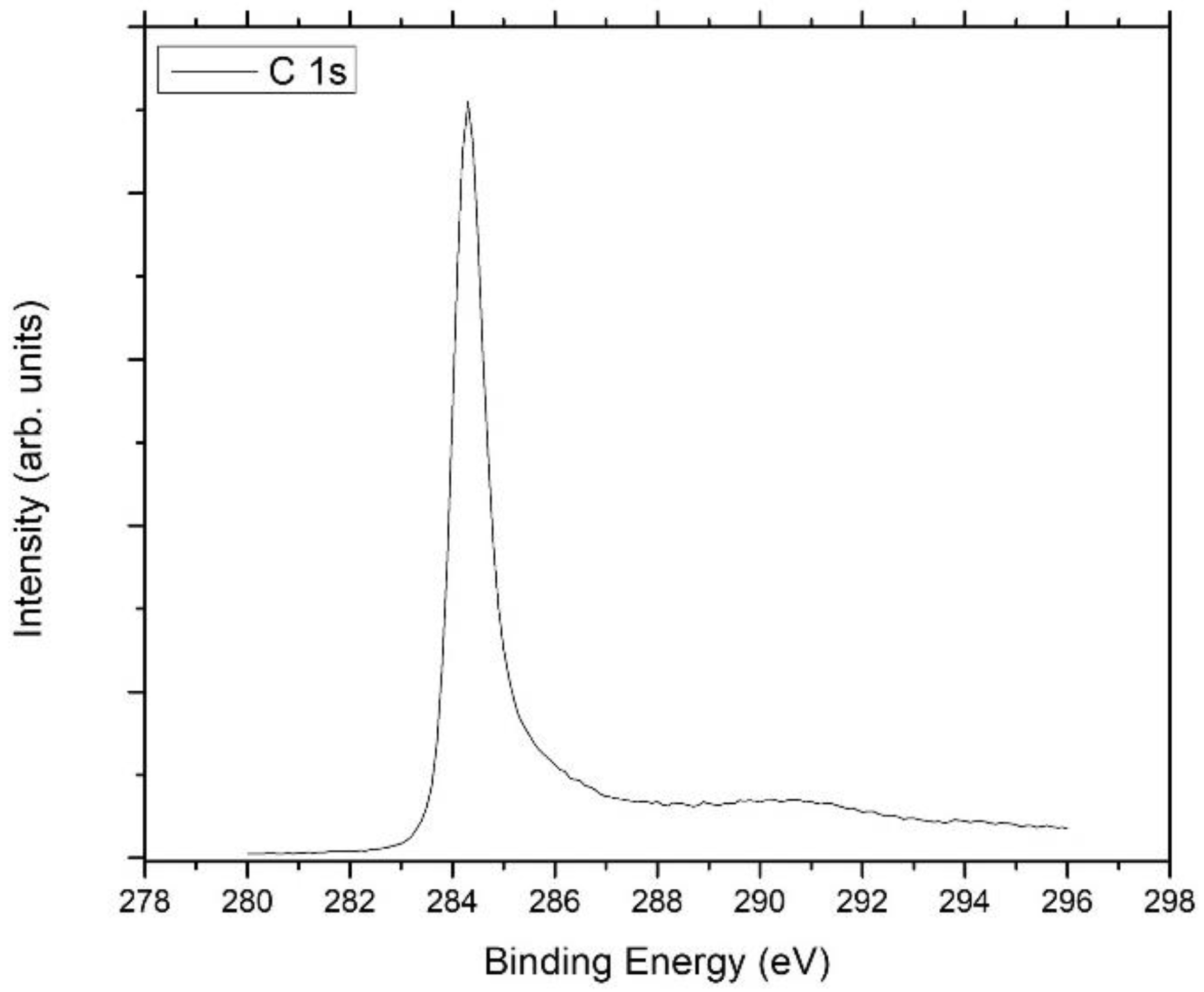
To better understand any chemical composition changes occurring here, representative sections of the longer tube-furnace-annealed fibers were characterized by XPS, with scans recorded for each annealing temperature. Three areas were scanned on each piece of fiber, with a general survey scan followed by detailed scans of the C 1s, O 1s, Fe 2p, Si 2p, and S 2p representations. The survey scans showed no observable deviation, with all of the chemical elements remaining throughout. Si 2p and S 2p were scanned as these chemicals are used in Nanocomp’s manufacturing process of CNT fibers and can potentially leave a residue. Table 1 shows the average percentage composition of the fibers after the respective annealing stage. All the way up to 700 °C, the relative carbon content does not significantly alter from ~95%, and the peaks did not show any change in shape either, with a representative C 1s peak shown in Figure 8; however, annealing at 500 °C reduced the carbon content slightly to 93.8%. It is also noticeable that annealing at 800 °C reduced the carbon content to 85%, although once again the shape of the C 1s peak did not change.
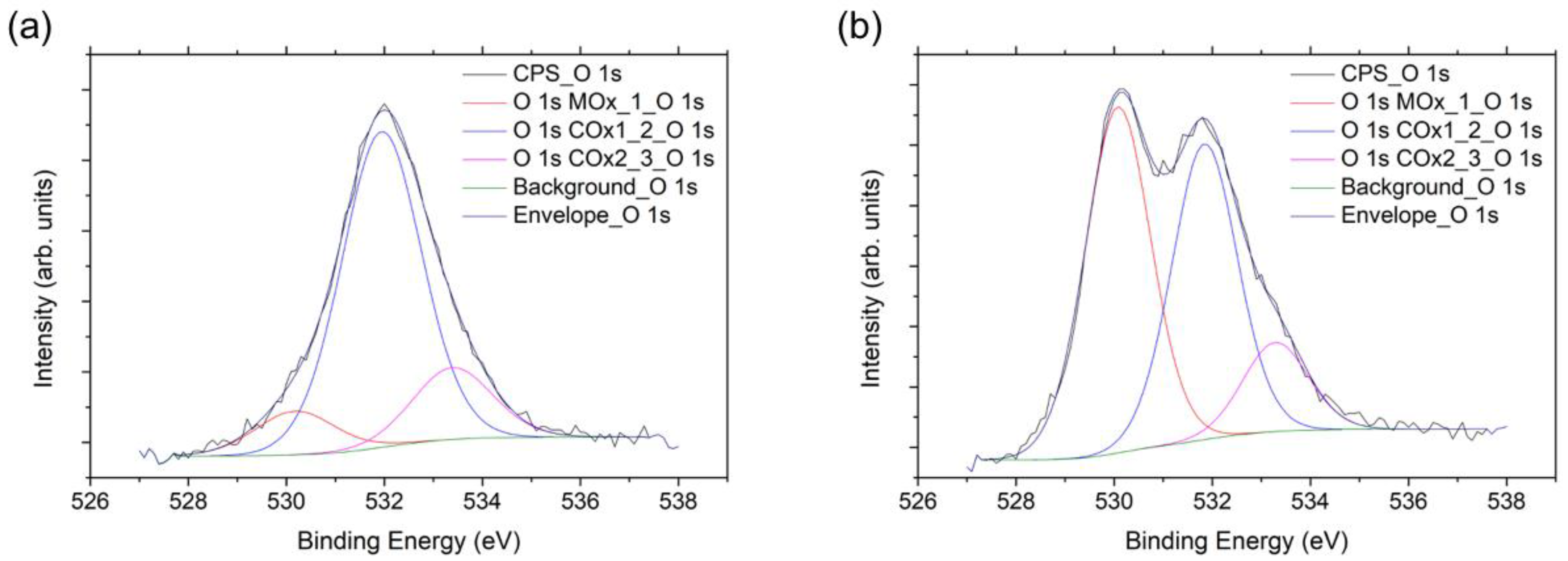
The O 1s peak was fitted with three component peaks, with the two positioned at 532.1 eV and 533.5 eV associated with oxygen–carbon bonds and the third being a metal-oxide peak positioned at a lower binding energy of 530.3 eV as shown in Figure 9a. Annealing up to 400 °C caused a gradual increase in the metal-oxide component from 8% to 19% of the total oxygen content; however, the overall quantity of oxygen relative to carbon remained constant. Annealing at 500 °C caused a significant increase in the metal-oxide peak to 36% of the total oxygen as seen in Figure 9b, which was then reduced to ~15% after annealing at 600 °C, 700 °C, and 800°C. After annealing at 800 °C, the percentage of oxygen content also increased to 10%.
The Fe 2p spectra showed that the iron consisted of Fe (0) and Fe (II/III) in all of the samples, and the quantity measured was low throughout. The percentage Fe was ~0.24% for fibers annealed at up to 300 °C, and this value increased to 0.34% and 0.68% for the fibers annealed at 400 °C and 500 °C, respectively. These increases were seen to be a result of a relative increase in the Fe (II/III) components which, combined with the oxygen peaks from before, heavily suggest the formation of iron oxides near the CNT-fiber surface from the oxidation of residual catalyst. Measurements of the fibers annealed at 600 °C and 700 °C showed that the Fe percentage had dropped to 0.24% again, and this was caused by a reduction in the Fe (II/III) components. The sample annealed at 800 °C had an increased iron content of 0.42% which, combined with the increase in the content of other elements and the decrease of the carbon content here, points towards the loss of CNTs at higher temperatures.
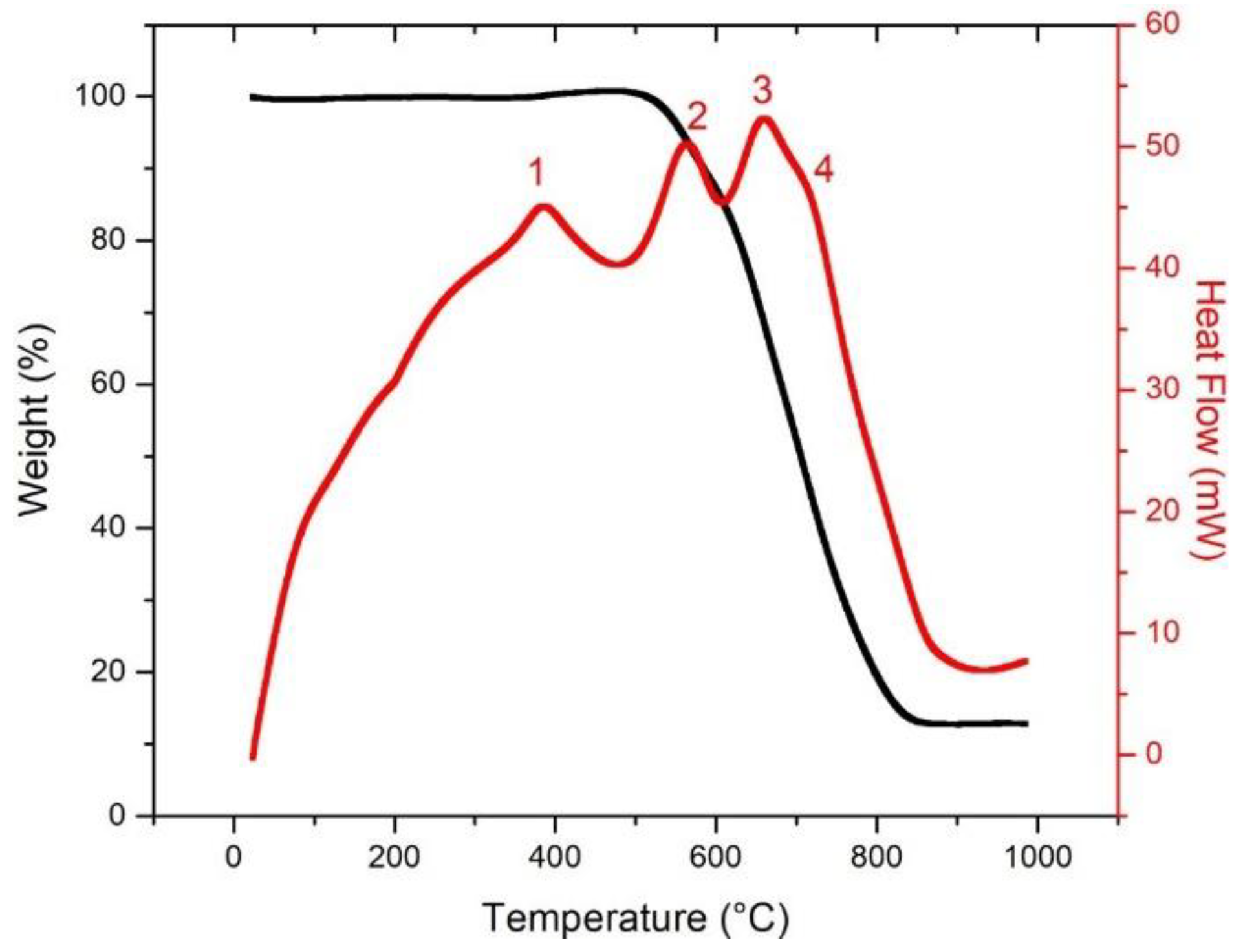
It is likely that the changes are more gradual than these discrete measurements suggest, and a thermogravimetric analysis was performed in order to understand this further. Figure 10 shows an example TGA plot for a piece of Nanocomp’s YE-A10 CNT fiber as is, with both weight loss and heat flow recorded as functions of temperature. Four exothermic peaks in heat flow (red) are marked, which are postulated to represent, in order, oxidation of amorphous carbon (1), oxidation of Fe to FeO in addition to the oxidation of any present single-walled CNTs (2), oxidation of multi-walled CNTs (3), and oxidation of FeO to Fe2O3/Fe3O4 (4) [21,25].
With this basis set, TGA was performed on the fibers annealed in the tube furnace, given that there was enough material remaining to do so. Figure 11a shows the heat-flow exotherm for the fiber annealed at 300 °C, with Figure 11b and 11c doing the same for the fibers annealed at 500 °C and 700 °C, respectively. Given the inherent inhomogeneity of the Nanocomp single-ply YE-A10 fiber, the relative intensities of the exotherms are the takeaway points here, and they show that the fibers annealed to increasing temperatures have already gone through the four stages in the series, including the removal of amorphous carbon, which then yields a fiber with a higher IG/ID and a lower electrical resistance, as well as the eventual oxidation of the conductive CNTs, thus leaving behind iron oxide, as seen by XPS, and resulting in a higher electrical resistance due to disruption of the conduction pathways. The actual temperatures of the exotherms need not match the annealing temperatures owing to the different annealing environment, including operating pressure, and it is the relative trends that are relevant here.
4. Conclusions
The scope of this work was initially limited to understanding the effect of thermal annealing on the localized electrical resistance of CNT fibers. A retail spool of Nanocomp’s single-ply YE-A10 was purchased accordingly, with the use of an Omicron nanoprobe to both thermally anneal short sections and measure the electrical resistance afterward. There was a clear observation of the Goldilocks principle, i.e., “not too hot, not too cold, just right” [26], with the fibers annealed at 500 °C having a three-orders-of-magnitude reduction in electrical resistance relative to the fiber as is. This led to the performance of a more thorough study, with voltage annealing shown to have a similar effect. Scaled-up tests were performed in a tube furnace which showed similar results, while also providing enough material for further characterization using XPS and TGA in order to indicate the selective removal of non/less-conductive amorphous carbon and CNT self-repair as the primary reasons for the increased conductance. There are also fewer conduction pathways now, with the electrons able to take the path of least resistance with fewer hopping steps in between. Annealing at higher temperatures/voltage results in irreversible changes that cause a significant increase in resistance, often exceeding the starting value. Our results indicate that this is more to do with the loss of conductive CNT materials, with less-conductive catalysts either remaining as is or as oxides. The conduction pathways are also different now, and all of this contributes to fibers that are annealed at 700–800 °C not being viable as starting materials for further processing and electrical conduction applications. This is effectively a purification protocol, although one that has currently only been studied on the localized surface of the CNT fiber and not the bulk fibers. Further research is ongoing to translate these findings to the bulk scale, as well as to better optimize the purification of CNT fibers.
Author Contributions
V.S.G., C.J.B. and J.D.M. conceptualized and performed the experiments, analyzed the results, and contributed to writing the manuscript. A.O.W. contributed towards discussions about the experiments and results. A.R.B. helped design the experiments, provided guidance to data analysis, and helped write the manuscript. All authors have read and agreed to the published version of the manuscript.
Funding
This work was supported by the Office of Naval Research (N00014-15-2717). V.S.G. funded thanks to Salts Healthcare Ltd. A.O.W. is funded through Sêr Cymru II Fellowship by the Welsh Government and the European Regional Development Fund (ERDF). A.O.W. acknowledges funding from Welsh Government Circular Economy Capital Fund FY 2020-21. The authors acknowledge access to the SEM and XPS provided by the Swansea University AIM Facility, funded in part by the EPSRC (EP/M028267/1) and (EP/N020863/1), the European Regional Development Fund through the Welsh Government (80708) and the Welsh Government’s Sêr Cymru program.
Data Availability Statement
The data presented in this study are available on request from the corresponding author.
Acknowledgments
We thank Bruce E. Brinson and W. Wade Adams for useful discussions. We would like to acknowledge the assistance provided by Swansea University AIM Facility.
Conflicts of Interest
The authors declare no conflict of interest. The funders had no role in the design of the study; in the collection, analyses, or interpretation of data; in the writing of the manuscript, or in the decision to publish the results.
References
- Peng, J.; He, Y.; Zhou, C.; Su, S.; Lai, B. The carbon nanotubes-based materials and their applications for organic pollutant removal: A critical review. Chin. Chem. Lett. 2021, 32, 1626–1636. [Google Scholar] [CrossRef]
- Prajapati, S.K.; Malaiya, A.; Kesharwani, P.; Soni, D.; Jain, A. Biomedical applications and toxicities of carbon nanotubes. Drug Chem. Toxicol. 2020, 1–16. [Google Scholar] [CrossRef] [PubMed]
- Anzar, N.; Hasan, R.; Tyagi, M.; Yadav, N.; Narang, J. Carbon nanotube—A review on Synthesis, Properties and plethora of applications in the field of biomedical science. Sens. Int. 2020, 1, 100003. [Google Scholar] [CrossRef]
- Jain, N.; Gupta, E.; Kanu, N.J. Plethora of Carbon Nanotubes Applications in Various Fields—A State-of-the-Art-Review. Smart Sci. 2021, 1–24. [Google Scholar] [CrossRef]
- Jarosz, P.; Schauerman, C.; Alvarenga, J.; Moses, B.; Mastrangelo, T.; Raffaelle, R.; Ridgley, R.; Landi, B. Carbon nanotube wires and cables: Near-term applications and future perspectives. Nanoscale 2011, 3, 4542–4553. [Google Scholar] [CrossRef] [PubMed]
- Bulmer, J.S.; Kaniyoor, A.; Elliott, J.A. A meta-analysis of conductive and strong carbon nanotube materials. Adv. Mater. 2021, 33, 2008432. [Google Scholar] [CrossRef]
- Hjortstam, O.; Isberg, P.; Soderholm, S.; Dai, H. Can we achieve ultra-low resistivity in carbon nanotube-based metal compo-sites? Appl. Phys. A Mater. Sci. Process 2004, 78, 1175–1179. [Google Scholar] [CrossRef]
- Janas, D.; Liszka, B. Copper matrix nanocomposites based on carbon nanotubes or graphene. Mater. Chem. Front. 2018, 2, 22–35. [Google Scholar] [CrossRef]
- Jordan, M.B.; Feng, Y.; Burkett, S.L. Development of seed layer for electrodeposition of copper on carbon nanotube bundles. J. Vac. Sci. Technol. B 2015, 33, 021202. [Google Scholar] [CrossRef]
- Subramaniam, C.; Sekiguchi, A.; Yamada, T.; Futaba, D.N.; Hata, K. Nano-scale, planar and multi-tiered current pathways from a carbon nanotube–copper composite with high conductivity, ampacity and stability. Nanoscale 2016, 8, 3888–3894. [Google Scholar] [CrossRef] [PubMed]
- Kang, C.S.; Lee, I.J.; Seo, M.S.; Kim, S.H.; Baik, D.H. Effect of purification method on the electrical properties of the carbon nanotube fibers. Fibers Polym. 2017, 18, 1580–1585. [Google Scholar] [CrossRef]
- Barnett, C.J.; Gowenlock, C.E.; Welsby, K.; Orbaek-White, A.; Barron, A.R. Spatial and Contamination-Dependent Electrical Properties of Carbon Nanotubes. Nano Lett. 2018, 18, 695–700. [Google Scholar] [CrossRef]
- Barnett, C.J.; Gowenlock, C.E.; White, A.O.; Barron, A.R. Pressure dependent conduction of individual multi-walled carbon nanotubes: The effect of mechanical distortions. Nanoscale Adv. 2021, 3, 643–646. [Google Scholar] [CrossRef]
- Barnett, C.J.; McGettrick, J.D.; Gangoli, V.S.; Kazimierska, E.; Orbaek White, A.; Barron, A.R. Effect of applied pressure on the electrical resistance of carbon nanotube fibres. Materials 2021, 14, 2106. [Google Scholar] [CrossRef] [PubMed]
- Gangoli, V.S.; Raja, P.M.V.; Esquenazi, G.L.; Barron, A.R. The safe handling of bulk low-density nanomaterials. SN Appl. Sci. 2019, 1, 644. [Google Scholar] [CrossRef] [Green Version]
- Cobley, R.; Brown, R.A.; Barnett, C.J.; Maffeis, T.G.G.; Penny, M.W. Quantitative analysis of annealed scanning probe tips using energy dispersive x-ray spectroscopy. Appl. Phys. Lett. 2013, 102, 23111. [Google Scholar] [CrossRef]
- Barnett, C.J.; Kryvchenkova, O.; Wilson, L.S.J.; Maffeis, T.G.G.; Kalna, K.; Cobley, R. The role of probe oxide in local surface conductivity measurements. J. Appl. Phys. 2015, 117, 174306. [Google Scholar] [CrossRef] [Green Version]
- Smith, N.A.; Lord, A.M.; Evans, J.E.; Barnett, C.J.; Cobley, R.J.; Wilks, S.P. Forming reproducible non-lithographic nano-contacts to assess the effect of contact compressive strain in nanomaterials. Semicond. Sci. Technol. 2015, 30, 065011. [Google Scholar] [CrossRef]
- Dresselhaus, M.; Dresselhaus, G.; Saito, R.; Jorio, A. Raman spectroscopy of carbon nanotubes. Phys. Rep. 2005, 409, 47–99. [Google Scholar] [CrossRef]
- Gangoli, V.S.; Godwin, M.A.; Joshi, S.S.; Allanavar, A.B.; Reddy, G.; Bradley, R.K.; Barron, A.R. The state of HiPco sin-gle-walled carbon nanotubes in 2019. C 2019, 5, 65. [Google Scholar]
- Zhang, K.S.; Pham, D.; Lawal, O.; Ghosh, S.; Gangoli, V.S.; Smalley, P.; Kennedy, K.; Brinson, B.; Billups, W.E.; Hauge, R.; et al. Overcoming catalyst residue inhibition of the functionalization of single-walled carbon nano-tubes via the Billups-Birch reduction. ACS Appl. Mater. Interfaces 2017, 9, 37972–37980. [Google Scholar] [CrossRef] [PubMed] [Green Version]
- Suherman, H.; Sulong, A.B.; Sahari, J. Effect of filler loading concentration, curing temperature and molding pressure on the electrical conductivity of CNTs/graphite/epoxy nanocomposites at high loading of conductive fillers. Int. J. Mech. 2010, 1, 74–79. [Google Scholar]
- Khanbolouki, P.; Tehrani, M. Purification, structural evolutions, and electrical properties of carbon nanotube yarns processed via incandescent annealing. Carbon 2020, 168, 710–718. [Google Scholar] [CrossRef]
- Orbaek, A.W.; Aggarwal, N.; Barron, A.R. The development of a ‘process map’ for the growth of carbon nanomaterials from ferrocene by injection CVD. J. Mater. Chem. A 2013, 1, 14122–14132. [Google Scholar] [CrossRef]
- Wright, K.D.; Barron, A.R. Catalyst Residue and Oxygen Species Inhibition of the Formation of Hexahapto-Metal Complexes of Group 6 Metals on Single-Walled Carbon Nanotubes. C 2017, 3, 17. [Google Scholar] [CrossRef] [Green Version]
- Obrey, S.J.; Bott, S.G.; Barron, A.R. A Lewis Base Promoted Alkyl/Alkoxide Ligand Redistribution: Reaction of [Me2Al(μ-OCPh3)]2 with THF. Organometallics 2001, 20, 5119–5124. [Google Scholar] [CrossRef]
Figure 1.
An example SEM image of two tungsten probes 20 µm apart and in contact with the CNT-fiber surface. The probes were used for a two-point-probe I-V measurement in an Omicron nanoprobe between the chosen voltage range as specified in the experimental conditions.
Figure 1.
An example SEM image of two tungsten probes 20 µm apart and in contact with the CNT-fiber surface. The probes were used for a two-point-probe I-V measurement in an Omicron nanoprobe between the chosen voltage range as specified in the experimental conditions.

Figure 2.
Example of an I-V measurement curve for Nanocomp YE-A10 CNT fiber as measured with two tungsten probes 20 µm apart in an Omicron nanoprobe using a voltage sweep from −1 to +1 V.
Figure 2.
Example of an I-V measurement curve for Nanocomp YE-A10 CNT fiber as measured with two tungsten probes 20 µm apart in an Omicron nanoprobe using a voltage sweep from −1 to +1 V.

Figure 3.
A semi-log plot of CNT fiber average electrical resistance as a function of annealing temperature in the nanoprobe. Electrical resistance drops to a minimum point followed by an irreversible increase.
Figure 3.
A semi-log plot of CNT fiber average electrical resistance as a function of annealing temperature in the nanoprobe. Electrical resistance drops to a minimum point followed by an irreversible increase.

Figure 4.
(a) Relative intensity of the G- and D-peaks in the resonant Raman spectra for CNT fibers at 785 nm as a function of annealing temperature in the nanoprobe and (b) electrical resistance of the CNT fibers as a function of the relative intensity of the G- and D-peaks. There is a general inverse relation of electrical resistance with IG/ID.

Figure 5.
A semi-log plot of CNT fiber average electrical resistance as a function of annealing voltage in the nanoprobe. Electrical resistance drops to a minimum point followed by an irreversible increase.
Figure 5.
A semi-log plot of CNT fiber average electrical resistance as a function of annealing voltage in the nanoprobe. Electrical resistance drops to a minimum point followed by an irreversible increase.

Figure 6.
A semi-log plot of CNT fiber average electrical resistance as a function of annealing temperature in a tube furnace. Electrical resistance drops to a minimum point followed by an irreversible increase.
Figure 6.
A semi-log plot of CNT fiber average electrical resistance as a function of annealing temperature in a tube furnace. Electrical resistance drops to a minimum point followed by an irreversible increase.

Figure 7.
(a) Relative intensity of the G- and D-peaks in the resonant Raman spectra for CNT fibers at 785 nm as a function of annealing temperature in the nanoprobe and (b) electrical resistance of the CNT fibers as a function of the relative intensity of the G- and D-peaks. There is a general inverse relation of electrical resistance with IG/ID.

Figure 8.
A representative C 1s XPS peak measured for fibers annealed in the tube furnace. The shape of the C 1s peak did not change with annealing temperature all the way to 800 °C.
Figure 8.
A representative C 1s XPS peak measured for fibers annealed in the tube furnace. The shape of the C 1s peak did not change with annealing temperature all the way to 800 °C.

Figure 9.
O 1s peak fits for the CNT fibers annealed at (a) 100 °C and (b) 500 °C showing the relative composition of oxygen content in the fibers varies, indicative of more metal oxide at the higher annealing temperature.
Figure 9.
O 1s peak fits for the CNT fibers annealed at (a) 100 °C and (b) 500 °C showing the relative composition of oxygen content in the fibers varies, indicative of more metal oxide at the higher annealing temperature.

Figure 10.
Thermogravimetry of Nanocomp YE-A10 CNT fiber with weight loss (%) and heat flow (mW) reported. There are four exotherms of interest here, which cater to compositional changes in the fiber and can explain the effect of fiber annealing better.
Figure 10.
Thermogravimetry of Nanocomp YE-A10 CNT fiber with weight loss (%) and heat flow (mW) reported. There are four exotherms of interest here, which cater to compositional changes in the fiber and can explain the effect of fiber annealing better.

Figure 11.
Heat-flow exotherms of the CNT fibers that were previously annealed at (a) 300 °C, (b) 500 °C, and (c) 700 °C, showing the four exotherms of interest here.
Figure 11.
Heat-flow exotherms of the CNT fibers that were previously annealed at (a) 300 °C, (b) 500 °C, and (c) 700 °C, showing the four exotherms of interest here.


Table 1.
Average elemental composition of CNT fibers annealed in tube furnace as measured by XPS.
| Annealing Temperature. (°C) | Carbon (%) | Iron (%) | Oxygen (%) | Sulphur (%) | Silicon (%) |
|---|---|---|---|---|---|
| 100 | 95.98 ± 0.64 | 0.24 ± 0.01 | 3.38 ± 0.58 | 0.14 ± 0.01 | 0.22 ± 0.05 |
| 200 | 95.29 ± 0.45 | 0.26 ± 0.01 | 3.90 ± 0.37 | 0.19 ± 0.02 | 0.32 ± 0.05 |
| 300 | 96.60 ± 0.40 | 0.24 ± 0.01 | 2.73 ± 0.39 | 0.13 ± 0.06 | 0.26 ± 0.05 |
| 400 | 96.56 ± 0.29 | 0.33 ± 0.02 | 2.83 ± 0.28 | 0.04 ± 0.01 | 0.22 ± 0.01 |
| 500 | 93.78 ± 0.34 | 0.68 ± 0.07 | 4.89 ± 0.38 | 0.13 ± 0.01 | 0.50 ± 0.03 |
| 600 | 94.52 ± 0.42 | 0.24 ± 0.01 | 4.36 ± 0.32 | 0.15 ± 0.01 | 0.70 ± 0.11 |
| 700 | 95.25 ± 0.50 | 0.24 ± 0.02 | 3.71 ± 0.37 | 0.03 ± 0.01 | 0.74 ± 0.17 |
| 800 | 85.18 ± 2.56 | 0.42 ± 0.05 | 10.66 ± 1.47 | 0.00 ± 0.00 | 3.73 ± 1.05 |
Publisher’s Note: MDPI stays neutral with regard to jurisdictional claims in published maps and institutional affiliations. |
© 2021 by the authors. Licensee MDPI, Basel, Switzerland. This article is an open access article distributed under the terms and conditions of the Creative Commons Attribution (CC BY) license (https://creativecommons.org/licenses/by/4.0/).
Share and Cite
MDPI and ACS Style
Gangoli, V.S.; Barnett, C.J.; McGettrick, J.D.; Orbaek White, A.; Barron, A.R. Increased Electrical Conductivity of Carbon Nanotube Fibers by Thermal and Voltage Annealing. C 2022, 8, 1. https://0-doi-org.brum.beds.ac.uk/10.3390/c8010001
AMA Style
Gangoli VS, Barnett CJ, McGettrick JD, Orbaek White A, Barron AR. Increased Electrical Conductivity of Carbon Nanotube Fibers by Thermal and Voltage Annealing. C. 2022; 8(1):1. https://0-doi-org.brum.beds.ac.uk/10.3390/c8010001
Chicago/Turabian StyleGangoli, Varun Shenoy, Chris J. Barnett, James D. McGettrick, Alvin Orbaek White, and Andrew R. Barron. 2022. "Increased Electrical Conductivity of Carbon Nanotube Fibers by Thermal and Voltage Annealing" C 8, no. 1: 1. https://0-doi-org.brum.beds.ac.uk/10.3390/c8010001
Note that from the first issue of 2016, this journal uses article numbers instead of page numbers. See further details here.