
Laser Additive Manufacturing of Fe-Based Magnetic Amorphous Alloys

Department of Material Science and Engineering, University of Sheffield, Sheffield S1 3JD, UK
*
Author to whom correspondence should be addressed.
Magnetochemistry 2021, 7(2), 20; https://0-doi-org.brum.beds.ac.uk/10.3390/magnetochemistry7020020
Submission received: 16 December 2020
/
Revised: 22 January 2021
/
Accepted: 25 January 2021
/
Published: 29 January 2021
(This article belongs to the Special Issue Soft and Hard Magnetic Materials: Latest Advances and Prospects)
Abstract
:Fe-based amorphous materials offer new opportunities for magnetic sensors, actuators, and magnetostrictive transducers due to their high saturation magnetostriction (λs = 20–40 ppm) and low coercive field compared with polycrystalline Fe-based alloys, which have high magnetostriction but large coercive fields and Co-based amorphous alloys with small magnetostriction (λs = −3 to −5 ppm). Additive layer manufacturing (ALM) offers a new fabrication technique for more complex net-shaping designs. This paper reviews the two different ALM techniques that have been used to fabricate Fe-based amorphous magnetic materials, including the structural and magnetic properties. Selective laser melting (SLM)—a powder-bed fusion technique—and laser-engineered net shaping (LENS)—a directed energy deposition method—have both been utilised to fabricate amorphous alloys, owing to their high availability and low cost within the literature. Two different scanning strategies have been introduced by using the SLM technique. The first strategy is a double-scanning strategy, which gives rise to maximum relative density of 96% and corresponding magnetic saturation of 1.22 T. It also improved the glassy phase content by an order of magnitude of 47%, as well as improving magnetic properties (decreasing coercivity to 1591.5 A/m and increasing magnetic permeability to around 100 at 100 Hz). The second is a novel scanning strategy, which involves two-step melting: preliminary laser melting and short pulse amorphisation. This increased the amorphous phase fraction to a value of up to 89.6%, and relative density up to 94.1%, and lowered coercivity to 238 A/m. On the other hand, the LENS technique has not been utilised as much as SLM in the production of amorphous alloys owing to its lower geometric accuracy (0.25 mm) and lower surface quality, despite its benefits such as providing superior mechanical properties, controlled composition and microstructure. As a result, it has been commonly used for large parts with low complexity and for repairing them, limiting the production of amorphous alloys because of the size limitation. This paper provides a comprehensive review of these techniques for Fe-based amorphous magnetic materials.
1. Introduction
Functional magnetic materials (FMMs) have gained considerable interest for advanced engineering devices owing to their technical benefits for energy conversion, harvesting, transmission, sensing/actuation [1], and more recently for magnetic refrigeration applications, based on their magnetocaloric effects [2]. Fe-based soft magnetic materials are of great importance for sensors, transformers, and inductive devices because of their superior magnetic properties such as outstanding magnetic permeability, low coercivity, and good corrosion resistance [3,4,5,6].
In general, Fe-based soft magnetic alloys are used in two distinct categories of applications:
- For producing and utilising electromagnetic energy: due to their low cost and ecological reasons, the usage of soft magnetic materials comprises an important part of these applications because they have high magnetic permeability, low energy losses and high magnetic saturation. Fe-Si-based alloys are considered as the most representative materials for this area.
- For signal processing: Fe-Ni-based alloys are usually used in informatics, electronics, transducers, magnetic recording heads, microwave installations and so on [7].
In the last two decades, significant progress has been achieved in the understanding of alloy design in an attempt to enhance the glass forming ability (GFA) of soft magnetic amorphous materials [8]. Therefore, many new bulk amorphous alloys with large GFA and good magnetic properties have been reported [9,10,11,12,13,14]. Casting methods including injection moulding have been used for the production of magnetic bulk metallic glasses (BMG). Zhang and his team utilised casting technique to fabricate glassy toroidal cores having good magnetic properties [15]. They consisted of Fe66Co10Mo3.5P10C4B4Si2.5 BMG with an outer diameter of 10 mm and inner diameter of 6 mm, and showed low coercivity (1.0 A/m), high maximum magnetic permeability (450,000), low core loss (0.4 W/kg at 50 Hz) and maximum magnetic flux density (1 T) [15]. Nevertheless, dimensional limitations and poor mechanical properties restrict the use of casting techniques in the production of bulk metallic alloys.
Alternatively, to manufacture three-dimensional (3D) amorphous magnetic parts, powder metallurgy (PM), especially hot pressing and spark plasma sintering, has been extensively exploited [16,17,18]. To reduce the possibility of the deterioration of magnetic softness because of partial crystallisation in the amorphous matrix, it is necessary that consolidation behaviour and thermal stability of the glassy structure at elevated temperatures is controlled [19]. It is promising that the limitations of conventional techniques can be overcome by using additive manufacturing (AM) in the production of glassy magnetic alloys, which is discussed in detail in Section 3. This section also mentions the use of powder-bed fusion and directed energy deposition techniques in the fabrication of amorphous magnetic Fe-based alloys, and the effects of process parameters on the final magnetic and mechanical properties. To emphasise the importance of the amorphous magnetic materials, their properties are analysed and compared with those of polycrystalline materials in Section 2.
2. Amorphous Fe-Based Magnetic Alloys
Amorphous alloys for soft magnetic applications are often fabricated by rapid solidification of the melt [20,21]. They are generally prepared with the nearly 20% addition of metalloids (Si, B, Al, C and P) for Fe-based and Co-based alloys [7]. Si and B are important metalloids for glass formation and the amorphous structure stabilisation [21,22]. Typical chemical compositions are such that the combined compositions of Fe, Co, Ni elements are 70–85 atomic (at.)% and those of Si and B are 15–30 at.% in total. However, magnetic glassy alloys have a wide variety of compositions. This allows for a large range of soft magnetic properties to be achieved, which depend upon the demands of the application [23].
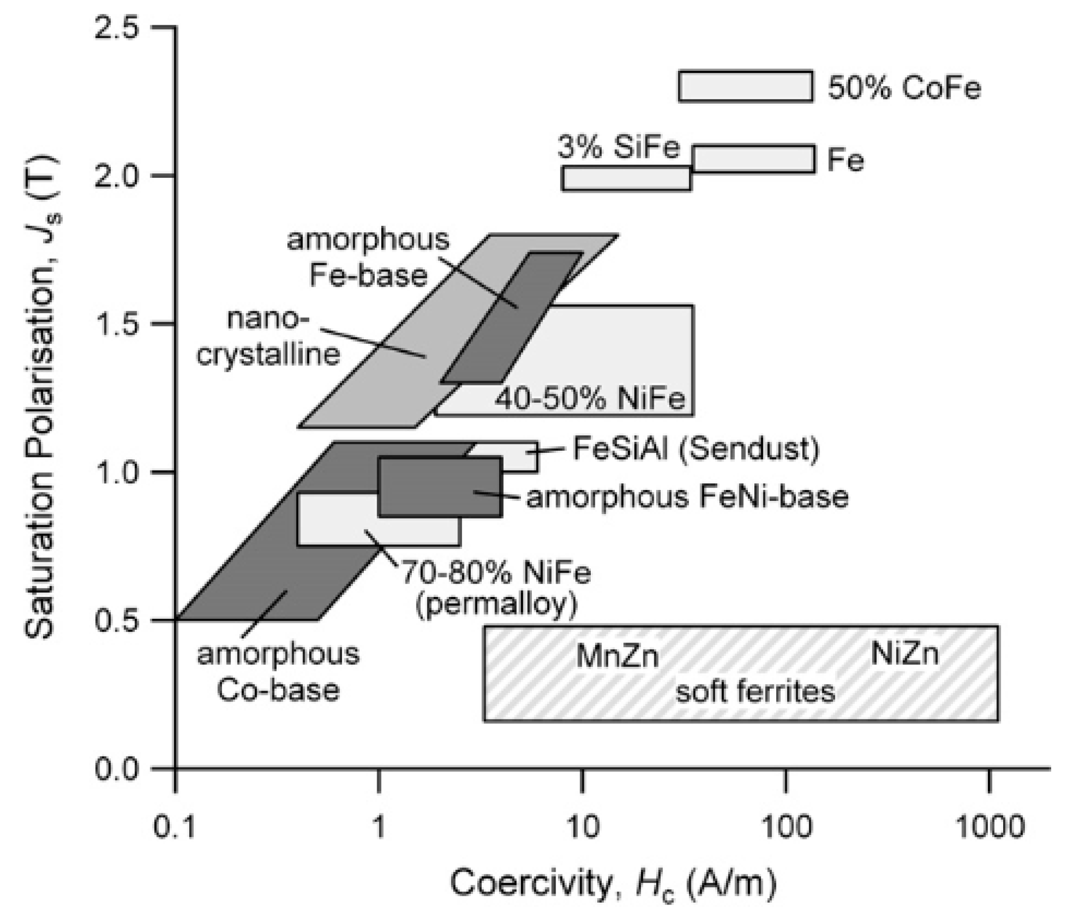
In magnetic amorphous alloys, the microstructure lacks atomic long-range order and only exhibits short-range order, which is essentially random atomic arrangement of the liquid melt solidified at a cooling rate of 105–106 K/s. As a result, there are no crystallite-related defects including grain boundaries and dislocations, leading to a decrease in coercivity (see Figure 1) [24].
Amorphous Fe-based alloys, based on inexpensive raw materials, have relatively high saturation magnetisation (see Figure 1) and high magnetostriction [23], which makes them promising candidates for sensors and actuators [25,26,27,28,29].
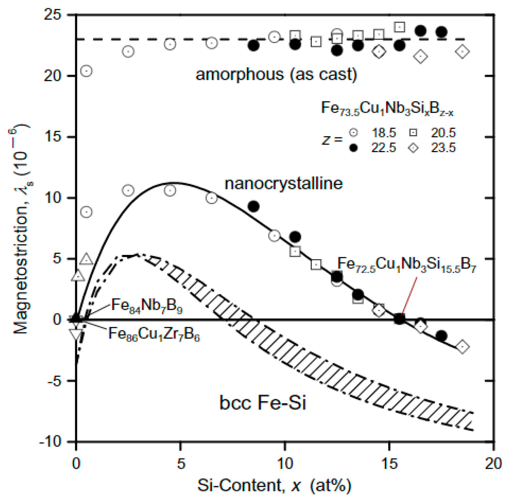
Figure 2 illustrates the relationship between the saturation magnetostriction constant and Si content for the FeCuNbSiB alloy system. The saturation magnetostriction (λs) has the highest value and is virtually independent of Si composition for the amorphous structure, different from the nanocrystalline state where magnetostriction is significantly dependent on the Si concentration and its maximum value is as nearly half that of the amorphous structure.
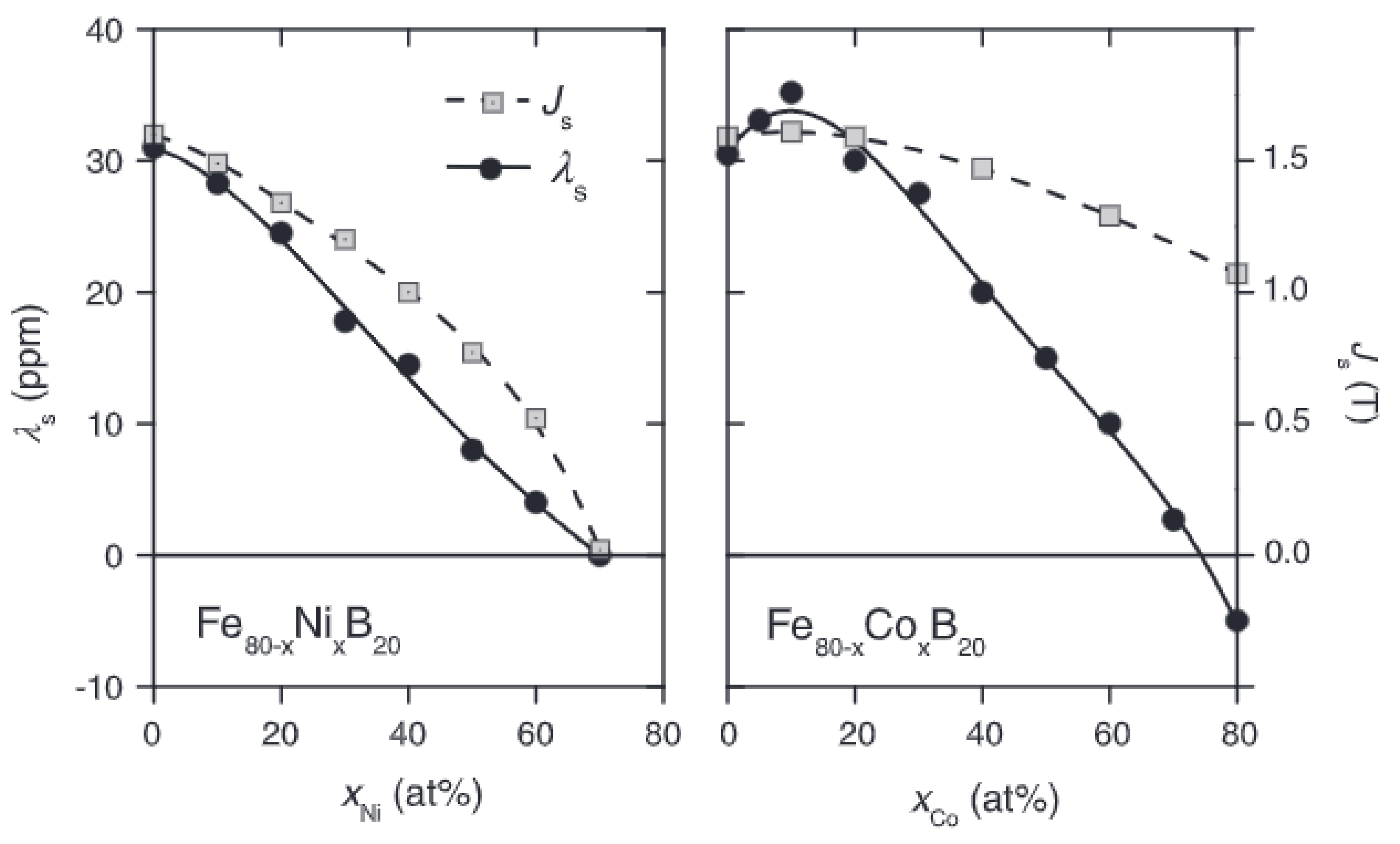
Figure 3 indicates the change in the saturation polarisation (Js) and the saturation magnetostriction constant (λs) of amorphous magnetic alloys as a function of Fe, Ni and Co content. Fe-rich alloys possess the highest saturation polarisation and saturation magnetisation constant, decreasing as Co and Ni concentration increases. Js for amorphous materials is usually lower than polycrystalline ones (Figure 1) because of the addition of nonmagnetic metalloids (Si and B) required for glass formation [23].
The saturation magnetostriction of Fe-based amorphous alloys is typically positive, ≈ 20–40 ppm, on the other hand for Co-based amorphous alloys, it is typically negative, ≈−5 to −3 ppm. The increase in λs with lowering Ni concentration is linked to a concurrent increase in Js (). Therefore, near zero λs at high Ni concentrations only occur as the system becomes paramagnetic [23].
Fe-B alloys with a saturation flux density higher than 1.5 T were the first metallic glass developed for the fabrication of distribution transformers. The addition of Si gave a higher thermal stability without any reduction in the saturation flux density, producing the ternary alloy Fe82B12Si6. However, this is prone to material oxidation due to air pockets forming during the production process, lowering magnetic flux density and increasing total losses. Fe81.5B13.5Si3C2 was developed to overcome these limitations [7].
Fe-Si-B glassy alloys possess six times fewer energy losses than traditional Fe-Si alloys at industrial frequencies. In fact, Fe79B13Si8 has a higher Curie temperature without changing core losses and flux density, compared with Fe-3%Si alloys in the fabrication of power transformers [7]. Therefore, they are competitive for applications where Fe-Si alloys are traditionally used.
After rapidly quenching of amorphous alloys, internal residual stresses are developed in the structure, altering the magnetic behaviour (increasing coercivity and reducing permeability) due to the emergence of magnetocrystalline anisotropy. Strain relief annealing has been employed below the crystallisation temperature not only to achieve higher permeability, lower energy losses and smaller coercivity (see Table 1), but also to improve mechanical properties by allowing atomic arrangement over a short distance. Table 1 clearly shows that although as-cast alloys exhibit very soft magnetic behaviour, strain relief annealing considerably allows the enhancement of magnetic properties (reducing coercivity, increasing permeability) by reliving the internal residual strains. Amorphous alloys with a wide variety of magnetic properties can be fabricated by annealing in the existence of an applied magnetic field [30].
There are a few limitations of using amorphous magnetic materials in certain applications. Firstly, their low saturation magnetisation restricts their usage in heavy current density engineering. Secondly, their core losses start to rise rapidly at high flux densities. For this reason, they have more use in low-power, low-current applications and specialised small-device applications where transformers are required with moderate flux densities. In these applications, amorphous magnetic materials can be used successfully instead of nickel-iron alloys including permalloy. Amorphous magnetic materials, being manufactured in large quantities, have been utilised in pulsed-power transformers, magnetic sensors, magnetostrictive transducers and communication equipment [30].
3. Additive Manufacturing of Amorphous Fe-Based Magnetic Alloys
Additive manufacturing (AM) includes a number of production techniques where components with a variety of structures and complex geometries are manufactured in a layer-by-layer manner directly from 3Reminder: make sure you write from … to …D model data [31,32,33,34,35]. The introduction of AM has influenced the whole fabrication field by making the design easy and simplifying the production process, enabling rapid production without needing major change in the fabrication step [36,37]. The economic advantage of AM is revealed especially in low-volume production [37].
Several Fe-based magnetic materials produced by additive manufacturing have been studied owing to their wide range of potential applicability in the energy area [38,39,40,41,42,43,44]. Additive manufacturing of amorphous Fe-based magnetic materials is focused on within this review paper. From the range of AM techniques, powder-bed fusion and direct energy deposition have been used for this purpose. This section reviews the AM of amorphous magnetic materials for different laser-based AM techniques, including the research carried out and the advantages and disadvantages of each method [1,45,46,47,48,49]. A summary table is given at the end of the section.
3.1. Powder-Bed Fusion
In the powder-bed fusion process, a thin layer (typically 20–100 µm) of very fine powder (with particle size in the range of 20–50 µm) [50] is spread closely packed on a platform. This is where the powder is then fused together with a laser beam or an electron beam. Once the fusion of one layer is completed, another layer of powder is rolled on top of the previous layer and melted together till the targeted 3D part is obtained (Figure 4). Powder size distribution and packing both influence significantly the density of the printed component, thus are the most critical factors, along with laser process parameters (laser scan speed, laser power, pulse duration and spot diameter), to the efficiency of this technique [51]. Selective laser sintering (SLS), used generally for various polymers and for some metals with the help of sacrificial binder materials, and selective laser melting (SLM), utilised only for certain metals are the two powder-bed fusion processes, which use a laser. In SLS process, only sintering occurs between powder particles once temperature is increased with a high-power laser above the softening point of polymers. On the other hand, in SLM technique, a relatively higher-powered laser is exploited to fully melt metallic powder instead of sintering it. Electron-beam melting (EBM) exploits an electron beam to melt the metal powder. Unlike SLS, in the SLM and EBM processes, the laser/electron beams can fully melt the metal powder and fuse them together, leading to exceptional mechanical properties [52].
In the literature, SLM has been widely utilised to produce amorphous magnetic materials due to their low cost and high availability. Different materials and applications that exploit SLM have been reviewed in detail in [53].
It is indicated that during SLM processes, solidification takes place relatively fast with typical cooling rates of 103–104 K/s, fast enough to prevent crystallisation, [54,55] even though the cooling rate is dependent on the process parameters [56]. For this reason, SLM is a promising technique to produce bulk amorphous parts.
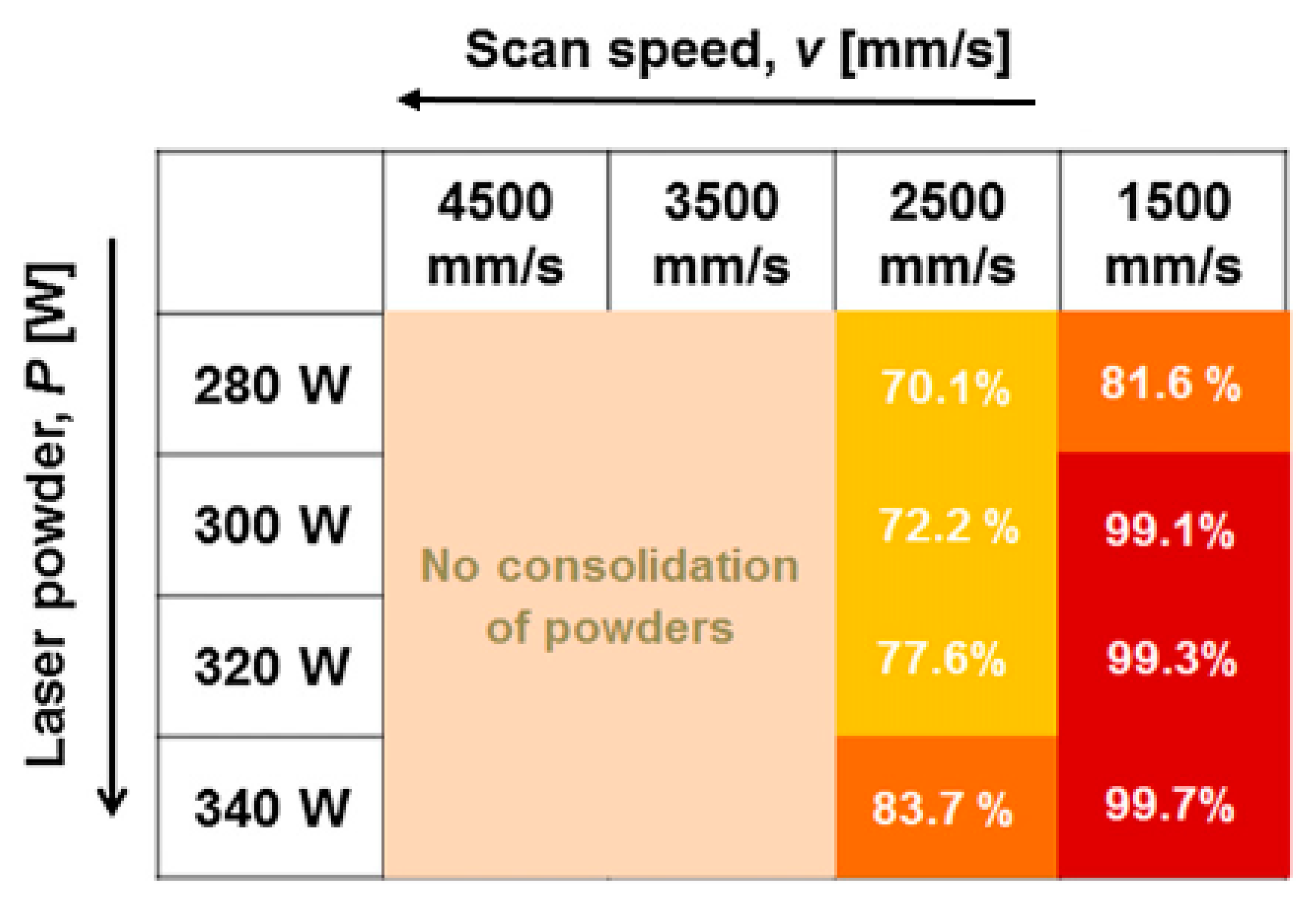
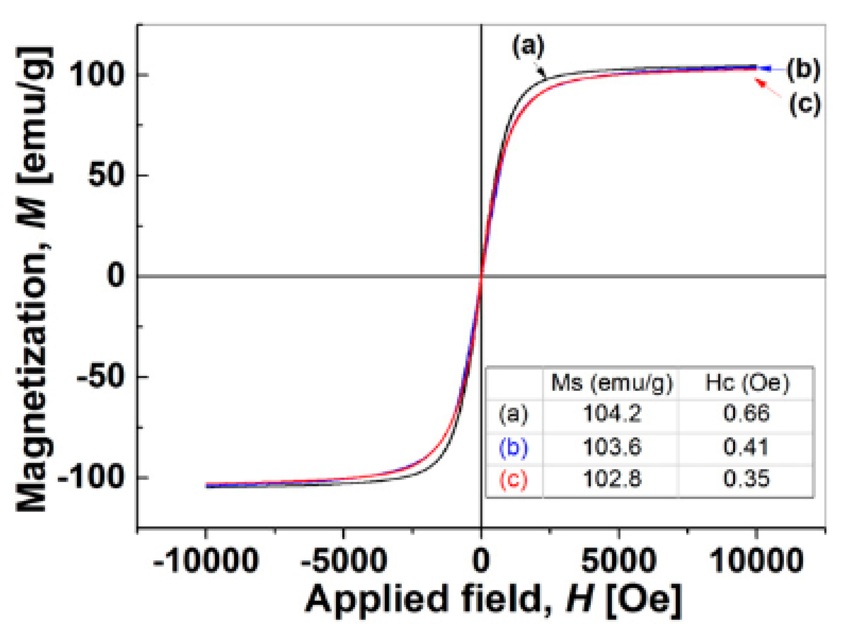
Fabrication of Fe-based bulk metallic glass with SLM has been studied firstly by Jung and his team [8]. Fe68.3C6.9 Si2.5B6.7P8.7Cr2.3Mo2.5Al2.1 (at.%) amorphous powder with different sizes in the range of 75 µm and 150 µm were prepared using gas atomisation. The cylindrical specimens with a diameter of 2 mm and height of 6 mm were built with the SLM technique. The microstructure of the final part was composed of a mixture of amorphous and α-Fe, γ-Fe and Fe23B6 crystalline phases, which are associated with impurities accidentally included in the master alloy. Also, the effect of the laser power (P) and scan speed (v) on the density of the final part and magnetic properties were examined in this study. It was concluded that at high scan speeds (v > 2500 mm/s), bulk parts could not be generated because the powder bed did not have sufficient energy input during the SLM process, which resulted in incomplete melting and poor inter-particle bonding [57,58,59]. At lower v and higher P, enhanced melting and consolidation of powder brings about the formation of SLM specimens having high relative densities (Figure 5). To achieve relative densities higher than 99%, it is vital that v lowers to 1500 mm/s and P is higher than 300 W. Moreover, hysteresis loops of the atomised powder and SLM specimens produced with different scan speeds obtained are illustrated in Figure 6. Figure 6 shows that the saturation magnetisation of all three samples are nearly the same within experimental error. The intrinsic magnetic properties including saturation magnetisation (Ms) are dependent on the atomic configuration and the composition of the soft amorphous magnetic materials [60], indicating that amorphous structures of the SLM specimens are identical to those of the starting atomised powder in this study.
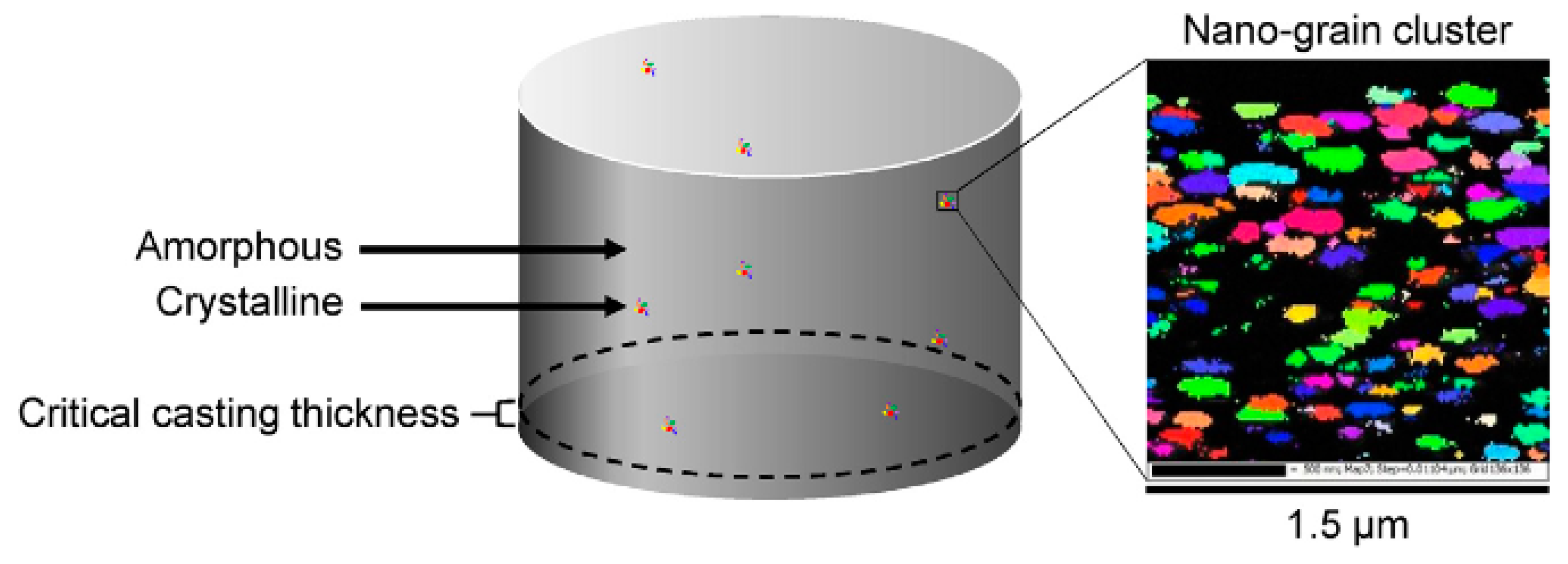
Mahbooba et al. tried to fabricate Fe-based BMG samples larger than critical casting thickness with SLM by using gas-atomised FeCrMoB powder with a nominal particle-size distribution of 20–80 µm [61]. It was reported that the thicknesses of the produced fully amorphous specimens (15 mm) were much more than the critical casting thickness (1 mm) in all dimensions. In addition, it was found that the change in the SLM parameters was not enough to prevent stress-induced micro-cracking because of rapid solidification and the brittle nature of BMGs. A low concentration of localised and isotropic nanograins, as shown in Figure 7, was present in the microstructure of the produced part due to mechanical stress-induced crystallisation. Furthermore, a mechanical test revealed that the Young’s modulus of the SLM bulk FeCrMoCB alloy (220 GPa) was fairly close to the modulus of the cast amorphous alloys with similar composition (190–220 GPa) [62]. This means that amorphous materials having larger than their casting critical thickness can be fabricated using SLM with mechanical properties competing with those of cast amorphous alloys.
As mention in Section 2, Fe-Si-B BMGs have attracted much attention as technological materials resulting from their outstanding soft ferromagnetic properties, great amorphous phase forming ability (APFA) and exceptional mechanical properties [63,64]. Consequently, it is possible to use them as core materials sensors [65], biosensors [66] and distribution transformers. Mostly, the high APFA of Fe-B alloys enables the formation of the amorphous phase and Si makes additional contribution to it. A fully amorphous phase is achieved within the range of 5–26 at.% B and 0–29 at.% Si [67]. Accordingly, Fe92.4Si3.1B4.5 alloy was produced with SLM with a laser scan speed of 100–150 mm/s and laser power of 90 W by using gas-atomised powder having particle sizes less than 30 µm, purchased from NANOVAL company as Fe92.4Si3.1B4.5 amorphous powder [68]. Nanocrystalline α-Fe0.95Si0.05 and Fe2B phases in an amorphous ε-FeSi type matrix was observed in the microstructure. The immoderate number of impurity atoms in the interstitial sites is linked to the formation of the amorphous ε-FeSi type structure by distorting the crystal lattice locally. The strong attraction between Fe and Si atoms indicates that APFA may be comparatively high in the Si composition above 20 at.% Si [67]. Furthermore, the large negative heat of mixing between constituents (−26 kJ/mol for Fe-Si and –38 kJ/mol for Fe-B alloys [69]) allows short-range order in the liquid upon laser melting. The crystallite sizes of α-Fe0.95Si0.05 and Fe2B, retained from the starting powder, decreases with increasing laser scan speed due to the high solidification rate (106–108 K/s). Such a fast solidification of droplets hinders the nucleation and growth of the crystallites, bringing about the amorphous structure. On the other hand, it is found that lower laser scan speeds of 100 mm/s and 400 mm/s enable denser microstructure, having lower porosity.
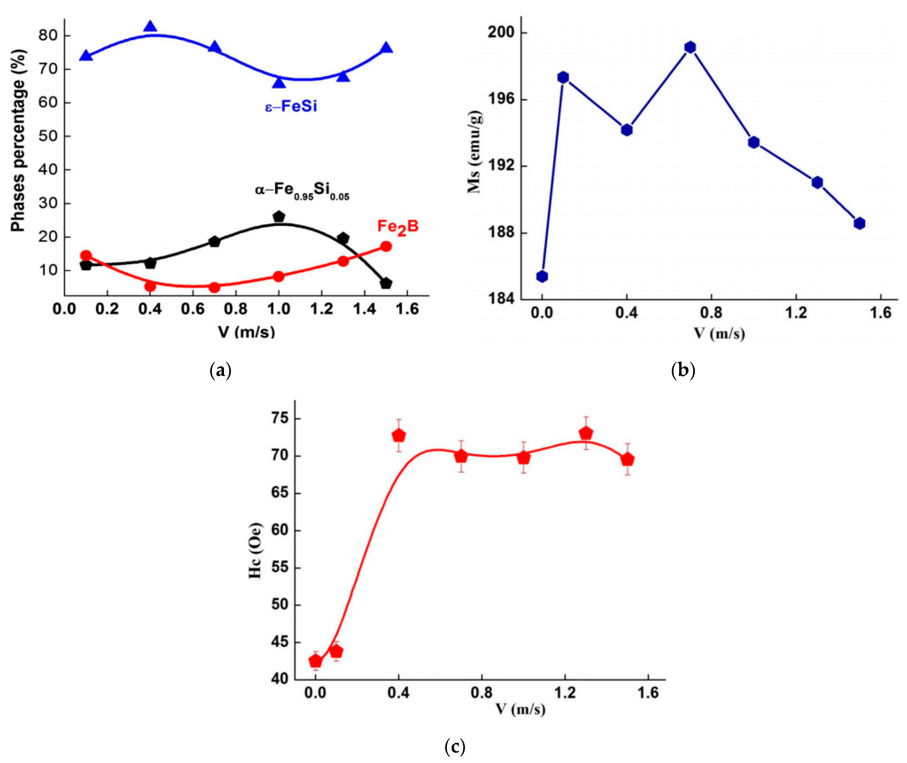
The change in the relative proportions of the phases as a function of laser scan speed (Figure 8a) depicts the variation in composition during the SLM process and therefore the atomic motion between distinct phases for Fe92.4Si3.1B4.5 alloys. The relative ratios of ε-FeSi type amorphous and α-Fe0.95Si0.05 phases show an antagonist behaviour in which the maximum relative ratio of ε-FeSi amorphous phase represents a minimum fraction of α-Fe0.95Si0.05 phase in the sample produced by using laser scan speed of 400 mm/s in this study. Consequently, it can be said that 400 mm/s is the optimum laser scan speed considering the process parameters used in this study to achieve both densification and high amorphous phase fractions for Fe-Si-B alloys. Furthermore, hardness was measured by a Vickers microhardness tester with a load of 100 gr. The high microhardness values (1654–2273 HV) were observed, linking to the crystallite size refinement as well as the dissolution of boron into the amorphous matrix. Those microhardness values are much higher than those of the Fe70Si10B20 produced by the modified melt spinning technique (830–110 HV) [64].
In the case of the magnetic performance of the SLM samples, it is observed that saturation magnetisation has maximum value of 199 Am2/kg for the sample fabricated with the laser scan speed of 700 mm/s and then decreases linearly to approximately 188 Am2/kg for that with 1500 mm/s as can be seen in Figure 8b). The alteration in the nearest-neighbour configuration of Fe atoms with their substitution by nonmagnetic Si atoms, causes a decrease in magnetic moment per atom, thus reducing Ms. Still, the specimens fabricated by SLM have much higher Ms values than FeSiB coatings produced by using the same starting powder (30–40 Am2/kg) [70].
How the coercivity (Hc) changes with respect to laser scanning speed is depicted in Figure 8c. It is obvious that Hc increases with increasing laser scanning speed up to 400 mm/s and then levels off. Since Hc is generally associated with the size, shape and the dispersion degree of the crystallites, including lattice distortion and internal stresses, high values of coercivity are attributed to the structural defects, such as vacancies and interstitials that originated from the laser melting process [68].
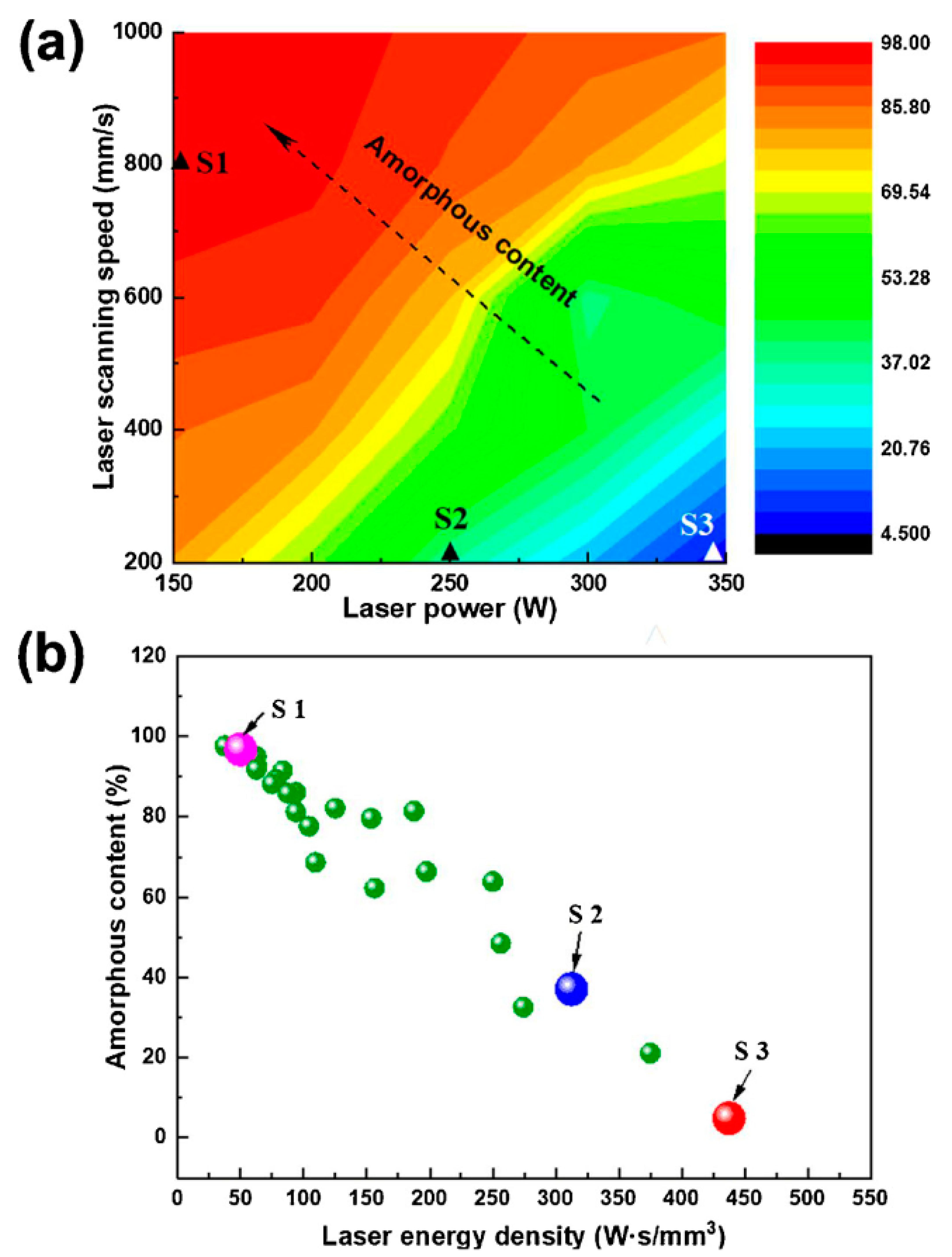
The study conducted by Ouyang et al. [71] confirms that the properties of selectively laser melted parts strongly depends on the mechanism of the microstructural development in amorphous alloys during the SLM process. In this study, in order to show the effect of SLM parameters on the microstructural evolution of Fe43.7Co7.3Cr14.7Mo12.6C15.5B4.3Y1.9 alloy, a map is made (Figure 9a). It indicates that low laser power (P < 200 W) and high laser scan speed (v > 700 mm/s) result in larger amorphous phase fractions. The relationship (Equation (1)) between amorphous content and laser energy input is attained (Figure 9b) based on the laser energy density equation, which is presented by:
where Ed is the energy input of energy density (J/mm3), P is the laser power (W), v is the laser scan speed (mm/s), h is the hatch distance (mm) and d is the thickness of the powder layer (mm) [72,73,74]. It is obvious that there is a linear transition from a nearly fully crystalline structure to a fully amorphous one as the Ed decreases. This may be because as energy density decreases, the cooling rate increases, leading to amorphous structure [75].
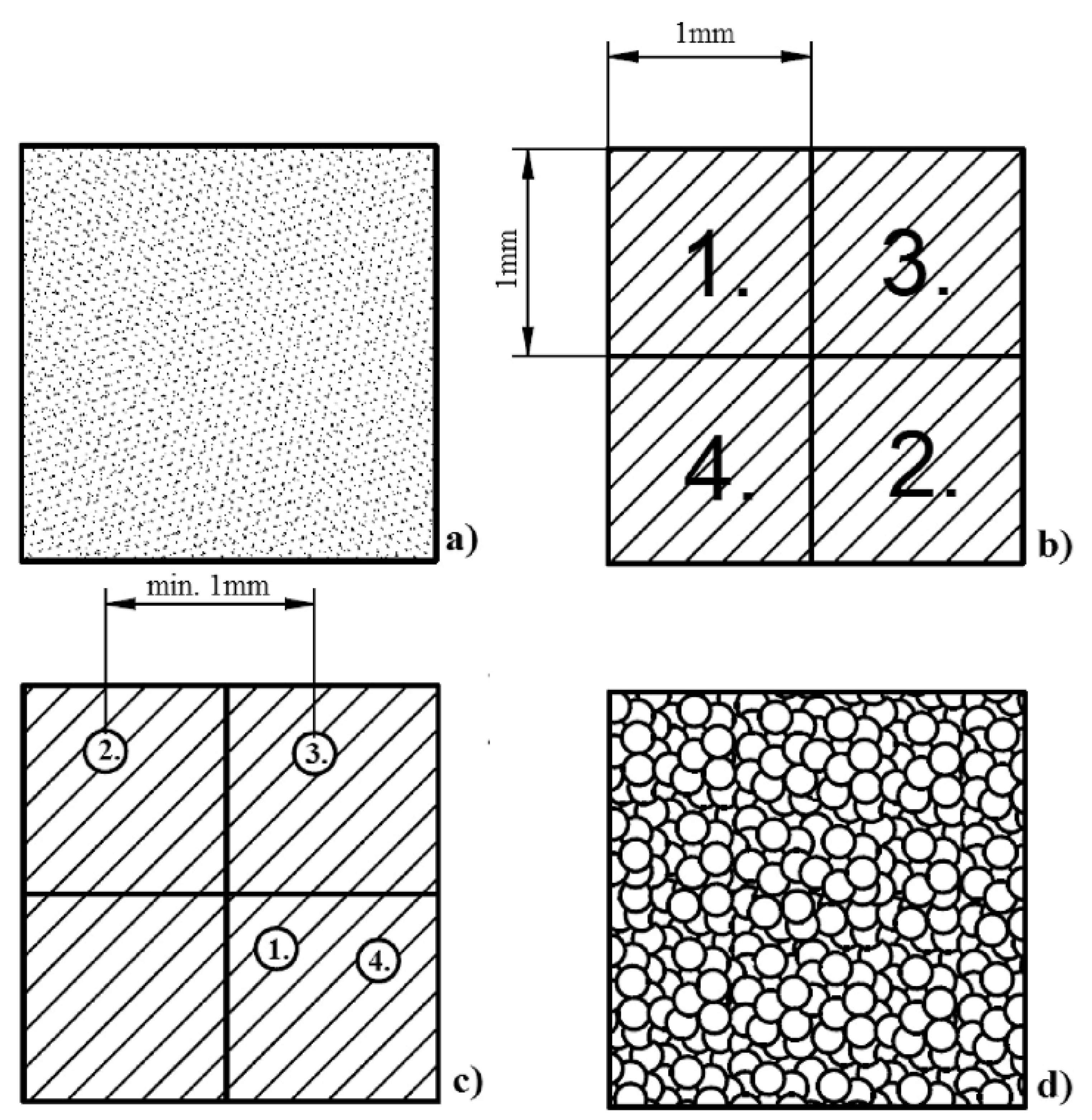
A novel scanning strategy has been introduced for amorphisation of Fe-based alloys with low glass forming ability with SLM as well as for ensuring enhanced magnetic properties [76]. For this purpose, Fe71Si10C6Cr2 (at.%) was used. The strategy comprises of (1) the preliminary laser melting the loose powder by using a checkboard strategy, (2) second melting (remelting) by random pulses (point-random (P-R) strategy) and (3) finally short-pulse amorphisation as shown in Figure 10. In the checkboard strategy, edge length of 1 mm and laser power of 20 W with 90o rotations (a standard alternating scanning strategy) were used with an exposure time of 500 µs. In the P-R strategy, minimum distance of 1 mm between successive points and maximum laser power of 120 W was exploited. Both melting processes were carried out by using the same focal diameter of 40 µm.
It is reported that the novel scanning strategy has enabled the restoration of 89.6% of the amorphous structure of the parent alloy in spite of its low glass-forming ability and considerable crystallisation during the preliminary melting. After P-R scanning (second melting), the amorphous phase appears as a continuous matrix, rather than forming separate regions, as is observed in the specimens produced with a single melting. In addition, second melting increases the density of bulk sample from 78.2% to 94.1%.
It is assumed that if the amorphous phase is heated by a laser pulse to a maximum temperature with a heating rate lower than the critical value, it devitrifies. In this study, the critical heating rate was calculated as 8.77 × 10⁶ K/s, at which the amorphous phase does not devitrify till the melting point of the material is reached. The heating rate for the preliminary melting (pulse duration (exposure time) 500 µs) (Sample A) was estimated as 2.5 × 10⁶ K/s, which is below the critical heating rate value. The heating rate of the second melting (P-R remelting with the pulse duration of 20 µs) (Sample B) was approximated as 6.25 × 10⁷ K/s, which is higher than the critical heating rate [76].
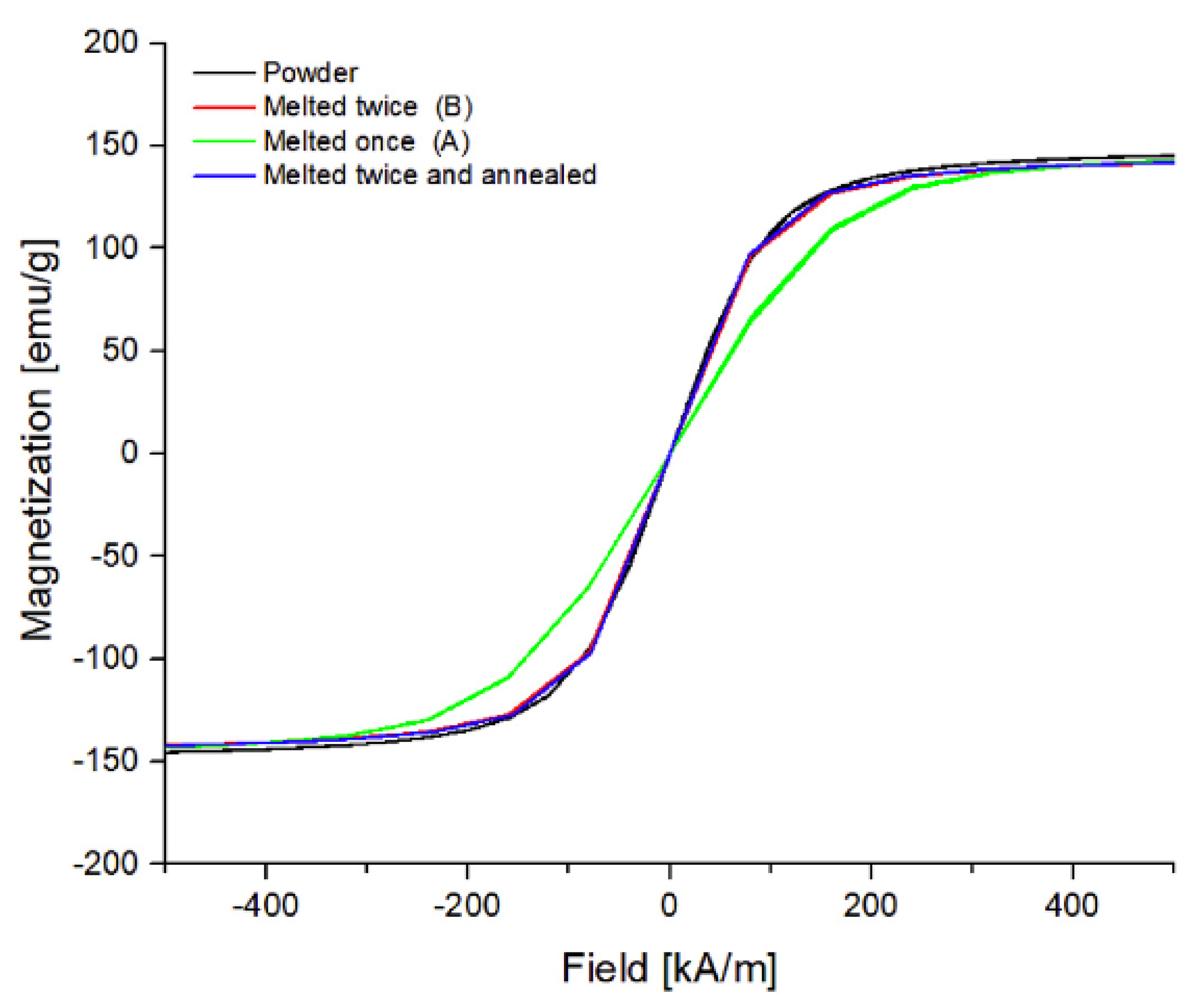
It is indicated that this strategy has a positive effect on soft magnetic properties. Coercivity was reduced substantially after the second melting (using P-R scanning) as seen in Table 2. Stress relief annealing at 820 K provided further reduction in coercivity. On the other hand, the M-H hysteresis loops (Figure 11) show that the saturation magnetisation seems to be the same for all samples except sample A within the margin of error.
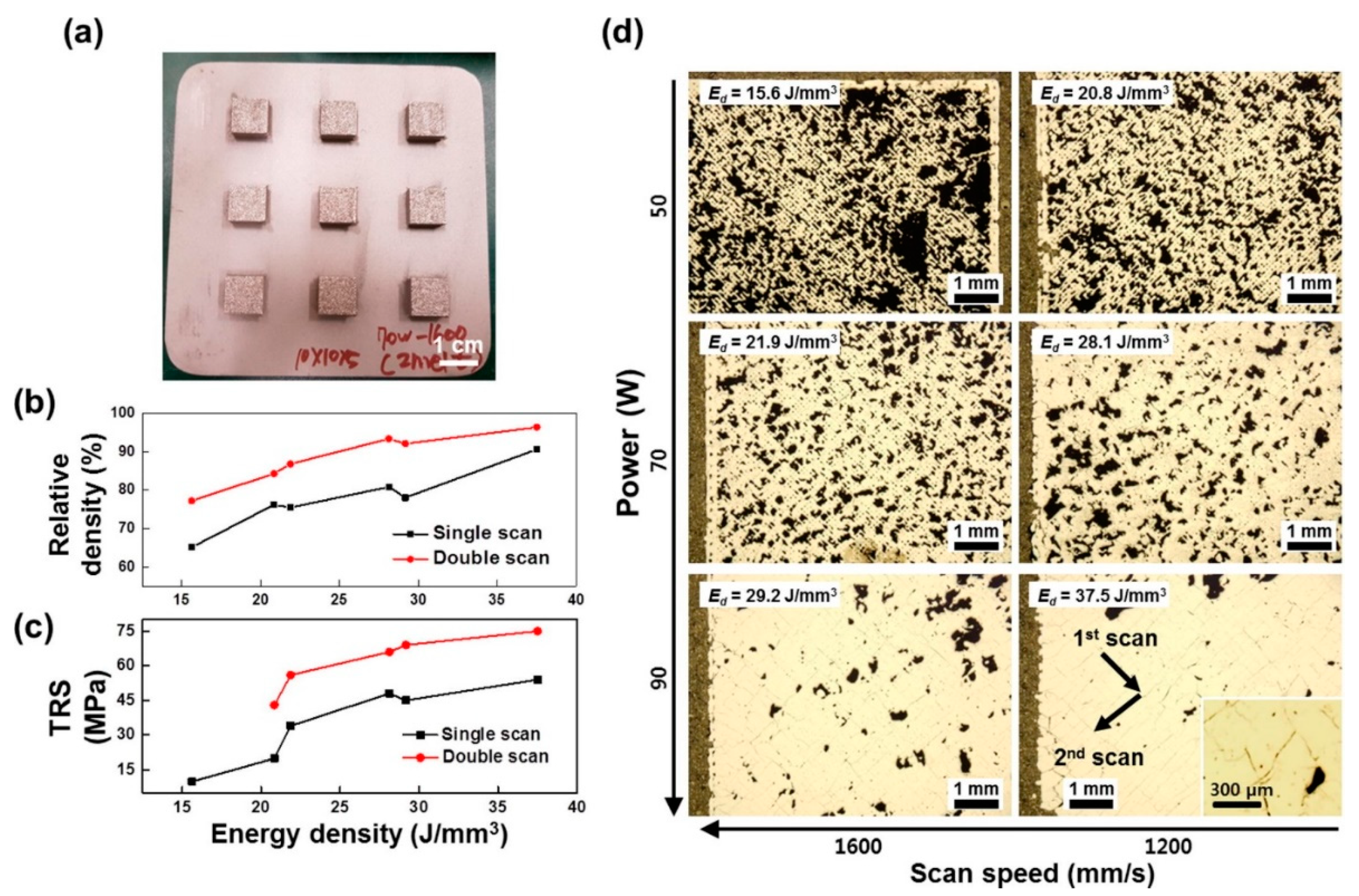
Most recently, Nam et al. have utilised a similar scanning technique as in Reference [76], referred to as the double-scan strategy, to achieve full verification and densification of Fe-based BMGs having high magnetic saturation [75]. In the double-scan strategy, before the coating of a subsequent powder layer over the build area, every Fe73.7Si11B11C2Cr2.28 amorphous powder layer was rescanned (remelted) with the linear scan method using the same laser power and laser scan speed as the first laser scanning. In this study, they compared the double-scanning strategy with a single scan in terms of relative density (Figure 12b), transverse rupture strength (TRS) (Figure 12c) and magnetic properties as a function of laser energy density, calculated using equation (1). It was found that double scanning enables effective shrinkage of voids formed because of partial melting of powder (Figure 12d), resulting in a relative density of maximum 96% and corresponding to the mechanical strength (TRS) of 75 MPa. This was achieved at the highest Ed of 37.5 J/mm3 (high power of 90 W and low scanning speed of 1200 mm/s) as it is shown in Figure 12d).
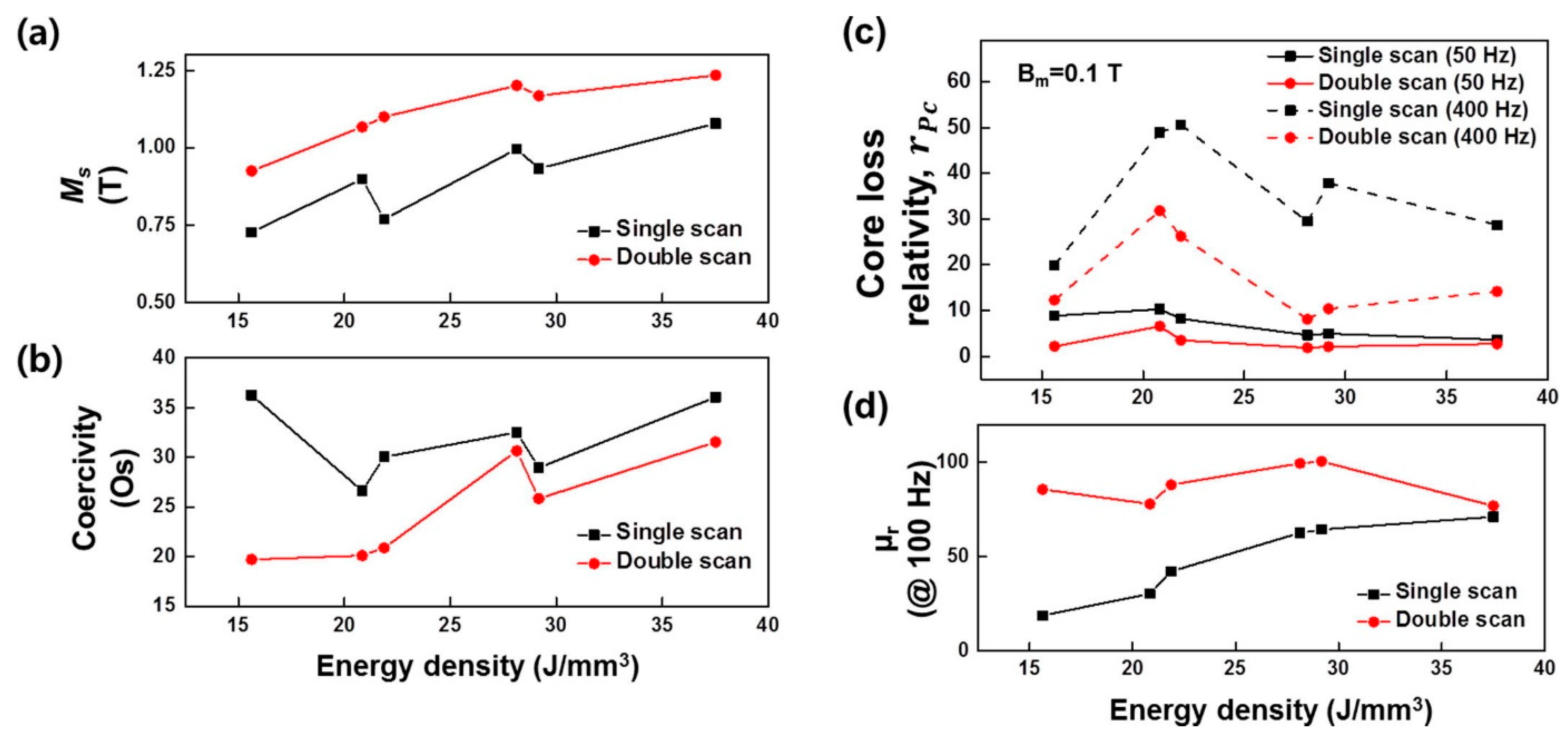
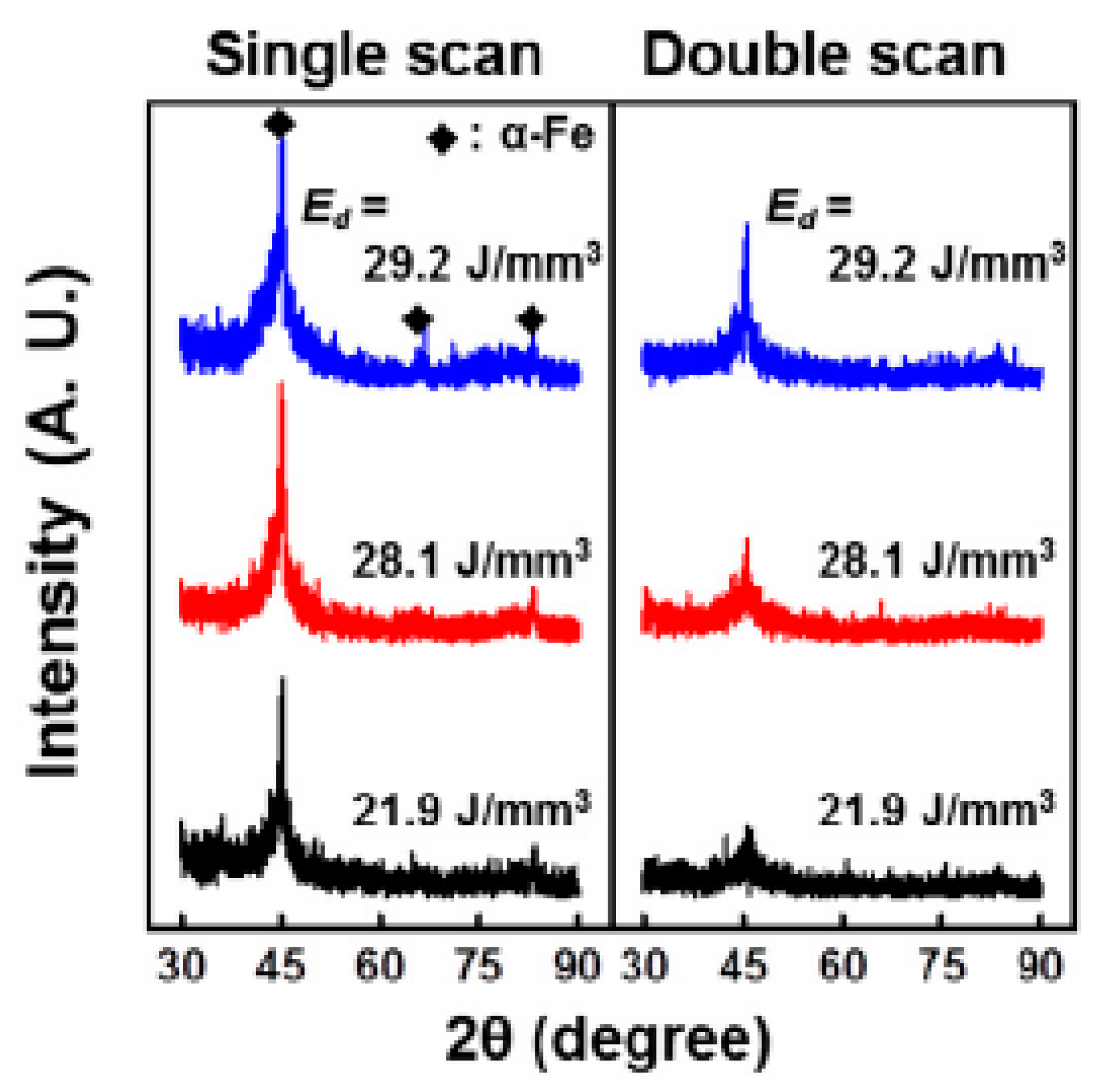
From the graphs in Figure 13, it is obvious that double scanning improves magnetic properties significantly. Magnetic saturation has a linear dependence on the Ed and a maximum Ms value of 1.22 T was attained with double scanning. Coercivity tends to increase with increasing Ed because higher Ed provides enough time for crystals to nucleate and grow, by lowering the cooling rate. This leads to a reduction in the amorphous fraction (fam), which was found to be 47% for Ed of 29.2 J/mm3. X-ray powder diffraction (XRD) results (Figure 14) show that the intensity of the α-Fe crystallite peak lowers as Ed decreases, implying that the fraction of the crystallite phase reduces.
In conclusion, SLM has been successfully used to produce Fe-based BMGs because it provides high cooling rates 103–104 K/s [54] but depends strongly on the process parameters used such as laser power and laser scan speed [56]. Low laser power and high laser scan speed leads to low energy input onto the powder, causing high cooling rate. Although decreasing the energy input, enables an increase in the amorphous fraction of the magnetic alloy, it affects adversely full densification, which requires a high energy density. Hence, low energy input results in poor mechanical properties (hardness and mechanical strength). It is crucial that optimum process parameters are defined for both full densification and amorphous structure. The studies indicate that double scanning (remelting) helps to increase the glassy phase content and relative density, and improve soft magnetic and mechanical properties [75].
3.2. Direct Energy Deposition
Direct energy deposition (DED) has been utilised for fabricating high-performance super-alloys. It contains several techniques, which are laser-engineered net shaping (LENS), laser solid forming (LSF), directed light fabrication (DLF), direct metal deposition (DMD), electron-beam AM (EBAM), and wire and arc AM (WAAW). In DED, laser or electron beams are used as a source of energy, which is directed onto a specific location of the substrate and exploited to melt feedstock materials (wires or powder) at the same time. Then, the molten materials are deposited and fused onto the substrate. This process continues layer by layer until the 3D part is built (Figure 15) [77]. Differently from SLM, DED has no powder bed and the feedstock is melted, then deposited into substrate in a layer-by-layer manner, enabling both multiple materials and multiple axis deposition simultaneously.
The LENS technique generally has been utilised to produce Fe-based BMGs because it provides (i) a high cooling rate (103–105 K/s) [79], (ii) less dilution at the substrate-layer interface, restricting crystallisation and (iii) tailorable process parameters with net shape production ability [80].
To prevent crystallisation in BMGs during the LENS process, laser power, laser scan speed and substrate temperature are the main parameters that can be controlled. The total heat input per unit area, I, is utilised to combine first two parameters along with the beam diameter as follows:
where P is the laser power (W), v is the laser scanning speed (mm/s), and D is the laser beam diameter on the substrate (mm) [81]. It is obvious from Equation (2) that reducing laser power and increasing laser scanning speed brings about a lower heat input [82], similarly to the SLM process as mentioned in Section 3.1. The lower the heat input, the higher the cooling rate due to high thermal gradients, which restricts crystallisation. Moreover, in order to maintain high cooling rates and obtain BMGs with maximum amorphous content, it is crucial that substrate temperature is kept as low as possible.
There are two ways to estimate the cooling rate during LENS processing. First one includes the use of the following equation:
where dT/dt (K/s) is the cooling rate, R (mm/s) is the solidification velocity and G (K/mm) is the local thermal gradient [83]. Through experiments, it has been presented that R is in the order of the laser scanning speed (v) [84], which is 20 mm/s in the study by Balla and his team [74], and G is approximately 100 K/mm [79]. Hence, by using this study, the cooling rate in the melt zone calculated using Equation (3) is approximated to be 2000 K/s, which is more than enough to produce an amorphous NSSHS7574 alloy with a critical cooling rate of 610 K/s [85]. Still, in order to make better estimations of cooling rates, it is necessary to take into consideration the substrate or prior deposit temperature, temperature change in the melt zone, laser input and the thermal conductivity of substrate and deposited alloys. Despite the complicated physics of laser surface melting [86,87], improved approximation of cooling rates during laser surface melting can be achieved by using the Rosenthal solution for a mobile heat source (Equation (4), as presented by Steen [87].
where k is the thermal conductivity of the substrate (W/mm.K), v is the laser scan speed (mm/s), Q is the laser power (W) and ΔT is the temperature range during cooling (K). It confirms that reducing the laser power and increasing the laser scan speed provides a higher cooling rate during laser-based additive manufacturing processes (Equation (4)). In addition, by using Equation (4), the cooling rates were quantified for different substrate/prior deposit temperature, which indicates that the cooling rate increases when the prior deposit temperature decreases (Equation (4)) [80].
In the production of Fe-based amorphous alloys with LENS, the initial attempt was made by Balla and Bandyopadhyay [80], who used a gas-atomised NanoSteel NSSHS7574 glass-forming alloy powder of Cr<25Mo<15W<10C<3Mn<5Si<2B<5Febalance (at.%) with a particle size in the range of 53 and 180 µm. Laser power of 250 W and laser scan speed of 20 mm/s were chosen to reduce heat input and to melt amorphous powder. In addition, even though no direct technique exists to control substrate and prior deposit temperature during the LENS process, in order to keep substrate temperature/prior deposit temperature low, a five-seconds delay was inserted between each successive layer with argon gas flowing through the powder delivery nozzles.
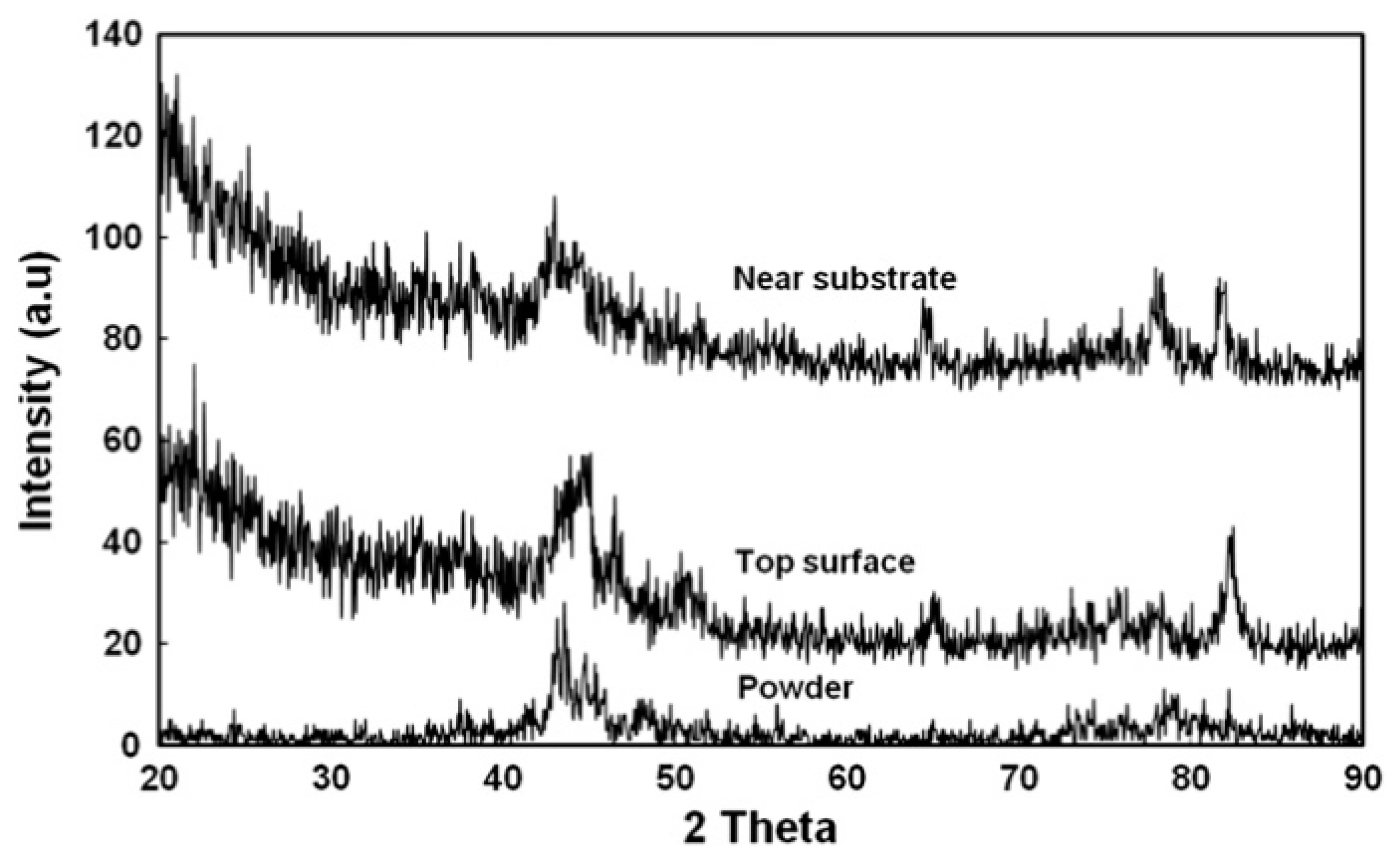
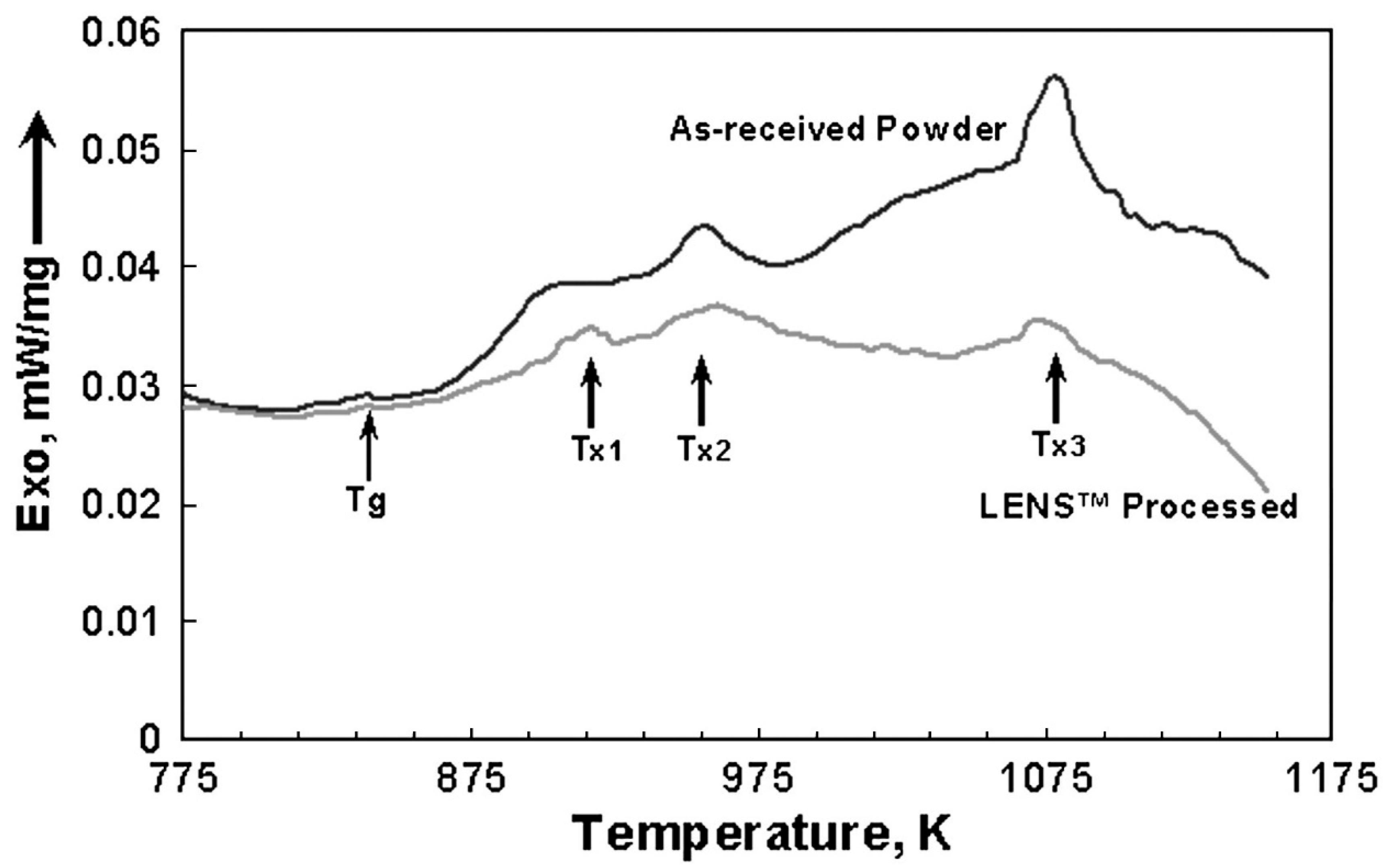
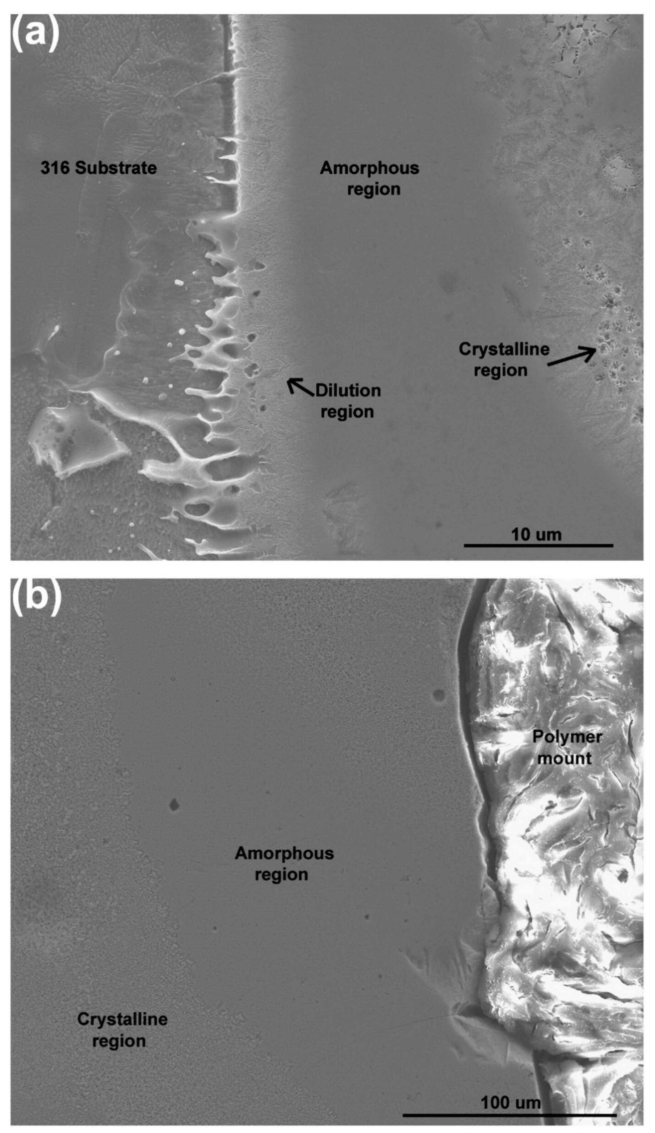
In this study, the cooling rate for the NSSHS7574 alloy was approximated to be in the range of 3.38 × 10³ and 1.72 × 10³ K/s using Equation (4), which is higher than the critical cooling rate (610 K/s) required for complete amorphisation of NSSHS7574 alloy. Even though theoretically the process parameters used in this study are ideal to obtain full amorphous alloys, XRD (Figure 16), differential scanning calorimetry (DSC) (Figure 17) and microstructural analysis (Figure 18) of the 3D-printed alloy exhibit partial crystallisation/incomplete amorphisation. It is thought that the reason for that is the coarse feedstock powder (53–108 µm), only partially melted during deposition because of the low heat input (14 J/mm2). Those partially melted particles are found in the deposit with melted and re-solidified surface having amorphous structure, surrounded with crystalline features as shown in Figure 18. It was concluded that to obtain fully amorphous alloys with the help of the LENS technique, the use of a finer starting powder would enable complete melting with the same process parameters, or increasing the heat input would allow for melting particles completely without influencing negatively the critical cooling rate needed to achieve full amorphisation [80].
Borkar et al. produced a compositionally graded Fe-Si-B-Nb-Cu alloy with varying Si/B ratios by using the LENS technique [5]. It was observed that dendrite formation occurred in the amorphous matrix, which is associated with constitutional super-cooling because of the compositional differences between the crystal and amorphous matrix [88,89,90]. The partitioning of Si at the interface of α-Fe/amorphous matrix causes the constitutional super-cooling, promoting the dendrite formation owing to interfacial instability. Furthermore, it was found that Fe-Si-B-Nb-Cu alloy with a Si/B ratio of 1.7 showed considerably low coercivity (1512 A/m) and higher magnetic saturation (143 Am2/kg) compared with the other FeSiBNbCu samples with different Si/B ratios.
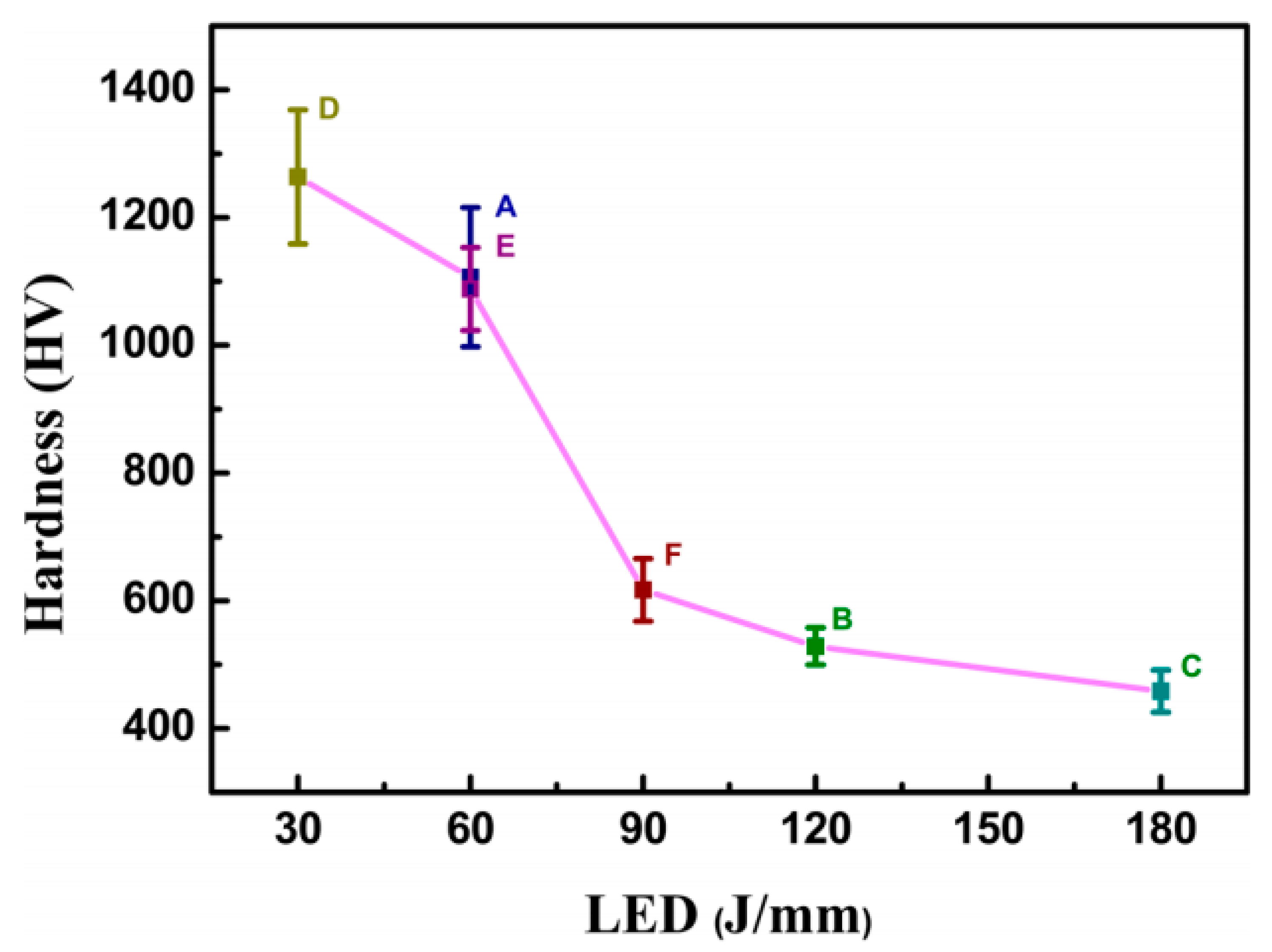
The effect of laser process parameters on the hardness of Fe-based BMGs produced by LENS was studied by Xie and his team [91], who used Fe41Co7Cr15Mo14C15B6Y2 (at.%) amorphous spherical powder and different laser energy densities. The variation in hardness as a function of laser energy density (LED) is illustrated in Figure 19. It is obvious that hardness increases as LED lowers. The use of the lowest energy density of 30 J/mm led to the highest hardness of 1263.7 HV. This value is significantly close to the hardness of cast Fe41Co7Cr15Mo14C15B6Y2 amorphous alloy (1253 HV) [92], which suggests that the printed specimen retained a certain amount of its amorphous phase.
In general, the LENS technique has not been much used in the production of magnetic amorphous alloys because it has lower geometric accuracy (0.25 mm) and lower surface quality, requiring post-processing [93] and can only fabricate less complicated components compared with SLM [77]. Consequently, LENS is commonly utilised for large parts with low complexity [34] and for repairing them [94], which restricts the fabrication of amorphous alloys by LENS due to their size limitation. All the drawbacks aside, the benefit of using LENS is the ability to produce parts with superior mechanical properties, controlled composition and microstructure [34]. As explained in this section, generating amorphous alloys with the LENS technique is possible by lowering laser energy input (low laser power and high scan speed similar to SLM) and reducing substrate/prior deposit temperature.
Table 3 gives a summary of the different materials and AM techniques described in this paper. It is observed that Fe-based magnetic alloys with various amorphous content up to 100% can be produced by the SLM technique by changing process parameters. It can be said that even though both of the elemental compositions and powder sizes of the feedstock powder in [75,76] are quite similar to each other, the SLM processes alloys have different amorphous phase fractions and magnetic properties due to the different process parameters and scanning strategy, as mentioned in Section 3.1. This means that laser process parameters and scanning strategy play critical roles in the production of amorphous alloys with laser additive manufacturing. From the perspective of magnetic properties, while the produced alloy in [8] possesses relatively low magnetic saturation and coercivity, the glassy alloy in Ref. [68] has relatively high saturation magnetisation and coercivity. This may due to the different alloy design and composition, process parameter or problems that occurred during the production, causing structural defects. It is indicated in Table 3 that SLM-processed glassy alloy (Fe71Si10C6Cr2 (at.%)) has the best soft magnetic properties (that is, high saturation magnetisation and low coercivity) resulting from the double-scanning strategy (remelting) carried out during the SLM process. The last three rows in Table 3 represent the Fe-based amorphous materials produced by the LENS technique. As stated before, the LENS technique has not been studied extensively in fabricating amorphous alloys due to the process-related problems. Considering the hardness values of the FeCrMoCB alloy produced by SLM [61] and the Fe41Co7Cr15Mo14C15B6Y2 (at.%) alloy fabricated by LENS [91], it can be said that LENS provides more mechanical strength than the SLM technique.
4. Conclusions
This paper provides a review of laser additive manufacturing found in the literature for Fe-based amorphous alloys. The literature demonstrates that laser additive manufacturing, which contains directed energy deposition and powder-bed fusion, is a promising process to produce Fe-based glassy alloys with good soft magnetic properties. The SLM technique from the powder-bed fusion category and the LENS technique from the directed energy deposition category have been used for that purpose within the literature, resulting from their high availability, low cost and being less time-consuming compared with the conventional techniques that have been used to produce amorphous alloys, such as casting. In both techniques, amorphous alloys were manufactured by altering the process parameters. Generally, low energy input, achieved via low laser power and high laser scanning speed, brings about increased amorphous phase content due to a higher cooling rate, but decreases relative density and deteriorates mechanical properties. To overcome this limitation, the double scanning (remelting) strategy has been employed, which results in enhancing both magnetic and mechanical properties. Additionally, in the LENS process, it is also necessary to consider the substrate/prior deposit temperature, to ensure that it is kept as low as possible to obtain a high cooling rate. SLM has been utilised more than LENS in the fabrication of Fe-based amorphous alloys, since LENS is not preferred for the production of small parts because of low geometric accuracy and poor surface quality. This contradicts with the size limitation of glassy alloys owing to their high critical cooling rates.
Author Contributions
Writing—original draft preparation, M.G.O.; writing—review and editing, M.G.O. and N.A.M.; supervision, N.A.M.; project administration, N.A.M.; funding acquisition, N.A.M. All authors have read and agreed to the published version of the manuscript.
Funding
This work was funded by the Ministry of National Education of Turkish Government, the Royal Society Mid-Career Leverhulme Trust Fellowship scheme (SRF\R1\180020) and the Leverhulme Trust (RPG-2018-324).
Data Availability Statement
No new data were created or analyzed in this study. Data sharing is not applicable to this article.
Conflicts of Interest
The authors declare no conflict of interest.
References
- Périgo, E.; Jacimovic, J.; Ferré, F.G.; Scherf, L. Additive manufacturing of magnetic materials. Addit. Manuf. 2019, 30, 100870. [Google Scholar] [CrossRef]
- Franco, V.; Blázquez, J.; Ipus, J.; Law, J.; Moreno-Ramírez, L.; Conde, A. Magnetocaloric effect: From materials research to refrigeration devices. Prog. Mater. Sci. 2018, 93, 112–232. [Google Scholar] [CrossRef]
- Smith, C.; Katakam, S.; Nag, S.; Zhang, Y.R.; Law, J.Y.; Ramanujan, R.V.; Dahotre, N.B.; Banerjee, R. Comparison of the Crystallization Behavior of Fe-Si-B-Cu and Fe-Si-B-Cu-Nb-Based Amorphous Soft Magnetic Alloys. Met. Mater. Trans. A 2014, 45, 2998–3009. [Google Scholar] [CrossRef]
- Wan, F.; He, A.; Zhang, J.; Song, J.; Wang, A.; Chang, C.T.; Wang, X. Development of FeSiBNbCu Nanocrystalline Soft Magnetic Alloys with High B s and Good Manufacturability. J. Electron. Mater. 2016, 45, 4913–4918. [Google Scholar] [CrossRef]
- Borkar, T.; Conteri, R.; Chen, X.; Ramanujan, R.; Banerjee, R. Laser additive processing of functionally-graded Fe–Si–B–Cu–Nb soft magnetic materials. Mater. Manuf. Process. 2017, 32, 1581–1587. [Google Scholar] [CrossRef]
- Yang, X.; Cui, X.; Jin, G.; Liu, J.; Chen, Y.; Liu, Z. Soft magnetic property of (Fe 60 Co 35 Ni 5) 78 Si 6 B 12 Cu 1 Mo 3 alloys by laser additive manufacturing. J. Magn. Magn. Mater. 2018, 466, 75–80. [Google Scholar] [CrossRef]
- Gavrila, H.; Ionita, V. Crystalline and Amorphous Soft Magnetic Materials and Their Applications—Status of Art and Challenges. J. Optoelectron. Adv. Mater. 2002, 4, 173–192. [Google Scholar]
- Jung, H.Y.; Choi, S.J.; Prashanth, K.G.; Stoica, M.; Scudino, S.; Yi, S.; Kühn, U.; Kim, D.H.; Kim, K.B.; Eckert, J. Fabrication of Fe-based bulk metallic glass by selective laser melting: A parameter study. Mater. Des. 2015, 86, 703–708. [Google Scholar] [CrossRef]
- Wang, J.; Li, R.; Hua, N.; Huang, L.; Zhang, T. Ternary Fe–P–C bulk metallic glass with good soft-magnetic and mechanical properties. Scr. Mater. 2011, 65, 536–539. [Google Scholar] [CrossRef]
- Shi, M.; Liu, Z.; Zhang, T. Effects of metalloid B addition on the glass formation, magnetic andmechanical properties of FePCB bulkmetallic glasses. J. Mater. Sci. Technol. 2015, 31, 493–497. [Google Scholar] [CrossRef]
- Li, Z.; Wang, A.; Chang, C.; Wang, Y.; Dong, B.; Zhou, S. FeSiBPNbCu alloys with high glass-forming ability and good soft magnetic properties. Intermetallics 2014, 54, 225–231. [Google Scholar] [CrossRef]
- Alvarez, K.L.; Martín, J.M.; Ipatov, M.; Gonzalez, J. Soft magnetic amorphous alloys (Fe-rich) obtained by gas atomisation technique. J. Alloy. Compd. 2018, 735, 2646–2652. [Google Scholar] [CrossRef]
- Jeziorski, L.; Nabialek, M.; Szota, M.; Dospial, M. Method of continuous casting of amorphous metallic materials based on iron. Arch. Foundry Eng. 2011, 11, 69–72. [Google Scholar]
- Nabialek, M.; Pietrusiewicz, P.; Dospial, M.; Szota, M.; Błoch, K.; Gruszka, K.; Ozga, K.; Garus, S. Effect of manufacturing method on the magnetic properties and formation of structural defects in Fe61Co10Y8Zr1B20 amorphous alloy. J. Alloy. Compd. 2014, 615, S51–S55. [Google Scholar] [CrossRef]
- Zhang, M.; Kong, F.; Wang, A.; Chang, C. Softmagnetic properties of bulk FeCoMoPCBSi glassy core prepared by copper mold casting. J. Appl. Phys. 2012, 111, 07A312. [Google Scholar] [CrossRef]
- Kim, Y.; Jang, D.; Seok, H.; Kim, K. Fabrication of Fe–Si–B based amorphous powder cores by cold pressing and their magnetic properties. Mater. Sci. Eng. A 2007, 449, 389–393. [Google Scholar] [CrossRef]
- Ishihara, S.; Zhang, W.; Kimura, H.; Omori, M.; Inoue, A. Consolidation of Fe–Co–Nd–Dy–B glassy powders by spark-plasma sintering andmagnetic properties of the consolidated alloys. Mater. Trans. 2003, 44, 138–143. [Google Scholar] [CrossRef] [Green Version]
- Yoshida, S.; Mizushima, T.; Makino, A.; Inoue, A. Structure and soft magnetic properties of bulk Fe–Al–Ga–P–C–B–Si glassy alloys prepared by consolidating amorphous powders. Mater. Sci. Eng. A 2001, 1, 1019–1022. [Google Scholar] [CrossRef]
- Inoue, A. Stabilization of metallic supercooled liquid and bulk amorphous alloys. Acta Mater. 2000, 48, 279–306. [Google Scholar] [CrossRef]
- Cahn, R. Rapidly Solidified Alloys; Marcel Dekker Inc.: New York, NY, USA, 1993. [Google Scholar]
- Davies, H.; Gibbs, M. Handbook of Magnetism and Advanced Materials; John Wiley and Sons: London, UK, 2007; Volume 4. [Google Scholar]
- Boll, R.; Hilzinger, H.; Warlimont, H. The Magnetic, Chemical and Structural Properties of Glassy Metallic Alloys; CRC Press: Boca Raton, FL, USA, 1983. [Google Scholar]
- Herzer, G. Modern soft magnets: Amorphous and nanocrystalline materials. Acta Mater. 2013, 61, 718–734. [Google Scholar] [CrossRef]
- Katakam, S.; Hwang, J.; Paital, S.; Banerjee, R.; Vora, H.; Dahotre, N. Laser-induced thermal and spatial nanocrystallization of amorphousFe–Si–B alloy. Scr. Mater. 2012, 66, 538–541. [Google Scholar] [CrossRef]
- Elhajjar, R.F.; Law, C.-T.; Pegoretti, A. Magnetostrictive polymer composites: Recent advances in materials, structures and properties. Prog. Mater. Sci. 2018, 97, 204–229. [Google Scholar] [CrossRef]
- Na, S.; Galuardi, J.; Flatau, A. Consolidation of magnetostrictive (001)-oriented Fe-Ga flakes for 3D printing powder materials. In Proceedings of the 2017 IEEE International Magnetics Conference (INTERMAG), Dublin, Ireland, 24–28 April 2017; p. 1. [Google Scholar]
- Al-Taher, A.; Reiss, R.; Lafferty, A.; Hayes, S.; Lupu, N.; Murgulescu, I.; Morley, N. Magnetostrictive Materials for aerospace applications. J. Phys. Conf. Ser. 2017, 903, 012010. [Google Scholar] [CrossRef]
- Hathaway, K.; Clark, A. Magnetostrictive Materials. Mater. Res. Soc. Bull. 1993, 4, 34–41. [Google Scholar] [CrossRef]
- Moron, C.; Cabrera, C.; Moron, A.; Garcia, A.; Gonzalez, M. Magnetic Sensors Based on Amorphous Ferromagnetic Materials: A Revie. Sensors 2015, 15, 28340–28366. [Google Scholar] [CrossRef] [Green Version]
- Jiles, D. Introduction to Magnetism and Magnetic Materials, 3rd ed.; CRC Press, Taylor and Francis Group: New York, NY, USA, 2016. [Google Scholar]
- Sun, Z.; Tan, X.; Tor, S.B.; Yeong, W.Y. Selective laser melting of stainless steel 316L with low porosity and high build rates. Mater. Des. 2016, 104, 197–204. [Google Scholar] [CrossRef]
- Sing, S.L.; An, J.; Yeong, W.Y.; Wiria, F.E. Laser and electron-beam powder-bed additive manufacturing of metallic implants: A review on processes, materials and designs. J. Orthop. Res. 2016, 34, 369–385. [Google Scholar] [CrossRef]
- Lee, J.M.; Yeong, W.Y. Design and Printing Strategies in 3D Bioprinting of Cell-Hydrogels: A Review. Adv. Health Mater. 2016, 5, 2856–2865. [Google Scholar] [CrossRef]
- Ngo, T.D.; Kashani, A.; Imbalzano, G.; Nguyen, K.; Hui, D. Additive manufacturing (3D printing): A review of materials, methods, applications and challenges. Compos. Part B Eng. 2018, 143, 172–196. [Google Scholar] [CrossRef]
- Singh, S.; Ramakrishna, S.; Singh, R. Material issues in additive manufacturing: A review. J. Manuf. Process. 2017, 25, 185–200. [Google Scholar] [CrossRef]
- Campbell, T.; Williams, C.; Ivanona, O.; Garrett, B. Could 3D Printing Change the World. In Technologies, Potential, and Implications of Additive Manufacturing; Atlantic Council: Washington, DC, USA, 2011. [Google Scholar]
- Goh, G.D.; Agarwala, S.; Goh, G.L.; Dikshit, V.; Sing, S.L.; Yeong, W.Y. Additive manufacturing in unmanned aerial vehicles (UAVs): Challenges and potential. Aerosp. Sci. Technol. 2017, 63, 140–151. [Google Scholar] [CrossRef]
- Taylor, A.P.; Velez, C.; Arnold, D.P.; Velásquez-García, L.F. Fully 3D-Printed, Monolithic, Mini Magnetic Actuators for Low-Cost, Compact Systems. J. Microelectromechanical Syst. 2019, 28, 481–493. [Google Scholar] [CrossRef]
- Patton, M.V.; Ryan, P.; Calascione, T.; Fischer, N.; Morgenstern, A.; Stenger, N.; Nelson-Cheeseman, B.B.; Ryan, P. Manipulating magnetic anisotropy in fused filament fabricated parts via macroscopic shape, mesoscopic infill orientation, and infill percentage. Addit. Manuf. 2019, 27, 482–488. [Google Scholar] [CrossRef]
- Díaz-García, Á.; Law, J.; Cota, A.; Bellido-Correa, A.; Ramírez-Rico, J.; Schäfer, R.; Franco, V. Novel procedure for laboratory scale production of composite functional filaments for additive manufacturing. Mater. Today Commun. 2020, 24, 101049. [Google Scholar] [CrossRef]
- Bollig, L.M.; Patton, M.V.; Mowry, G.S.; Nelson-Cheeseman, B.B. Effects of 3-D Printed Structural Characteristics on Magnetic Properties. IEEE Trans. Magn. 2017, 53, 1–6. [Google Scholar] [CrossRef]
- Arbaoui, Y.; Agaciak, P.; Chevalier, A.; Laur, V.; Maalouf, A.; Ville, J.; Roquefort, P.; Aubry, T.; Queffelec, P. 3D printed ferromagnetic composites for microwave applications. J. Mater. Sci. 2017, 52, 4988–4996. [Google Scholar] [CrossRef]
- Fafenrot, S.; Grimmelsmann, N.; Wortmann, M.; Ehrmann, A. Three-Dimensional (3D) Printing of Polymer-Metal Hybrid Materials by Fused Deposition Modeling. Materials 2017, 10, 1199. [Google Scholar] [CrossRef] [Green Version]
- Chaudhary, V.; Mantri, S.; Ramanujan, R.; Banerjee, R. Additive manufacturing of magnetic materials. Prog. Mater. Sci. 2020, 114, 100688. [Google Scholar] [CrossRef]
- Zhang, B.; Fenineche, N.-E.; Zhu, L.; Liao, H.; Coddet, C. Studies of magnetic properties of permalloy (Fe–30%Ni) prepared by SLM technology. J. Magn. Magn. Mater. 2012, 324, 495–500. [Google Scholar] [CrossRef]
- Mikler, C.V.; Chaudhary, V.; Borkar, T.; Soni, V.; Jaeger, D.; Chen, X.; Contieri, R.; Ramanujan, R.V.; Banerjee, R. Laser Additive Manufacturing of Magnetic Materials. JOM 2017, 69, 532–543. [Google Scholar] [CrossRef] [Green Version]
- Kustas, A.; Susan, D.; Johnson, K.; Whetten, S.; Rodriguez, M.; Dagel, D.; Micheal, J.; Keicher, D.; Argibay, N. Characterization of the Fe-Co-1.5V soft magnetic alloy processed by laser engineered net shaping (LENS). Addit. Manuf. 2018, 21, 41–52. [Google Scholar]
- Goll, D.; Schuller, D.; Martinek, G.; Kunert, T.; Schurr, J.; Sinz, C.; Schubert, T.; Bernthaler, T.; Riegel, H.; Schneider, G. Additive manufacturing of soft magnetic materials and components. Addit. Manuf. 2019, 27, 428–439. [Google Scholar] [CrossRef]
- Kang, N.; El Mansori, M.; Guittonneau, F.; Liao, H.; Fu, Y.; Aubry, E. Controllable mesostructure, magnetic properties of soft magnetic Fe-Ni-Si by using selective laser melting from nickel coated high silicon steel powder. Appl. Surf. Sci. 2018, 455, 736–741. [Google Scholar] [CrossRef] [Green Version]
- Song, X.; Zhai, W.; Huang, R.; Fu, J.; Fu, M.; Li, F. Metal-Based 3D-Printed Micro Parts & Structures. Ref. Modul. Mater. Sci. Mater. Eng. 2020. [Google Scholar] [CrossRef]
- Utela, B.; Storti, D.; Anderson, R.; Ganter, M. A review of process development steps for new material systems in three dimensional printing (3DP). J. Manuf. Process. 2008, 10, 96–104. [Google Scholar] [CrossRef]
- Lee, H.; Lim, C.H.J.; Low, M.J.; Tham, N.; Murukeshan, V.M.; Kim, Y.-J. Lasers in additive manufacturing: A review. Int. J. Precis. Eng. Manuf. Technol. 2017, 4, 307–322. [Google Scholar] [CrossRef]
- Yap, C.Y.; Chua, C.K.; Dong, Z.; Liu, Z.H.; Zhang, D.Q.; Loh, L.E.; Sing, S.L. Review of selective laser melting: Materials and applications. Appl. Phys. Rev. 2015, 2, 041101. [Google Scholar] [CrossRef]
- Pauly, S.; Löber, L.; Petters, R.; Stoica, M.; Scudino, S.; Kühn, U.; Eckert, J. Processing metallic glasses by selective laser melting. Mater. Today 2013, 16, 37–41. [Google Scholar] [CrossRef]
- Zheng, B.; Zhou, Y.; Smugeresky, J.E.; Lavernia, E.J. Processing and Behavior of Fe-Based Metallic Glass Components via Laser-Engineered Net Shaping. Met. Mater. Trans. A 2009, 40, 1235–1245. [Google Scholar] [CrossRef]
- Gu, D.; Meiners, W.; Wissenbach, K.; Poprawe, R. Laser additive manufacturing of metallic components: Materials, processes and mechanisms. Int. Mater. Rev. 2012, 57, 133–164. [Google Scholar] [CrossRef]
- Khan, M.; Dickens, P. Selective Laser Melting (SLM) of pure gold. Gold Bull. 2010, 43, 114–121. [Google Scholar] [CrossRef] [Green Version]
- Dayal, R. Numerical Modelling of Processes Governing Selective Laser Sintering. Ph.D. Thesis, Technische Universität Darmstadt, Darmstadt, Germany, 2014. [Google Scholar]
- Yuan, P.; Gu, D. Molten pool behaviour and its physical mechanism during selective laser melting of TiC/AlSi10Mg nanocomposites: Simulation and experiments. J. Phys. D Appl. Phys. 2015, 48, 035303. [Google Scholar] [CrossRef]
- Luborsky, F. Amorphous Metal Alloys; Butterworths: London, UK, 1983. [Google Scholar]
- Mahbooba, Z.; Thorsson, L.; Unosson, M.; Skoglund, P.; West, H.; Horn, T.; Rock, C.; Vogli, E.; Harryson, O. Additive manufacturing of an iron-based bulk metallic glass larger than thecritical casting thickness. Appl. Mater. Today 2018, 11, 264–269. [Google Scholar] [CrossRef]
- Suryanarayana, C.; Inone, A. Iron-based bulk metallic glasses. Int. Mater. Rev. 2013, 58, 131–166. [Google Scholar] [CrossRef]
- Efimov, Y.; Mukhin, G.; Lazarev, E.; Korotkov, N.; Ryabtsev, L.; Dmitriev, V.; Frolova, T. The structure of rapidly hardened Fe-Si-B alloys. Russ. Metall. 1986, 4, 167–173. [Google Scholar]
- Haginaro, M.; Inonue, A.; Masu, T. Mechanical properties of FeSiB amorphous wires produced by in-rotating-water spinning method. Metall. Mater. Trans. A 1982, 13, 373–382. [Google Scholar]
- Suwa, Y.; Agatsuma, S.; Hashi, S.; Ishiyama, K. Study of strain sensor using FeSiB magnetoresistive thin films. IEEE Trans. Magn. 2010, 46, 666–669. [Google Scholar] [CrossRef]
- Li, S.; Horikawa, S.; Park, M.-K.; Chai, Y.; Vodyanoy, V.J.; Chin, B.A. Amorphous metallic glass biosensors. Intermetallics 2012, 30, 80–85. [Google Scholar] [CrossRef]
- Inoue, A.; Komuro, M.; Masumoto, T. Fe-Si-B amorphous alloys with high silicon concentration. J. Mater. Sci. 1984, 19, 4125–4132. [Google Scholar] [CrossRef]
- Alleg, S.; Drablia, R.; Fenineche, N. Effect of the Laser Scan Rate on the Microstructure, Magnetic Properties, and Microhardness of Selective Laser-Melted FeSiB. J. Supercond. Nov. Magn. 2018, 31, 3565–3577. [Google Scholar] [CrossRef]
- de Boer, F.; Boom, R.; Mattens, W.; Miedema, A.; Niessen, A. Cohesion in Metals; North-Holland: Amsterdam, The Netherlands, 1988. [Google Scholar]
- Dong, S.; Song, B.; Zhang, X.; Deng, C.; Fenineche, N.; Hansz, B.; Liao, H.; Coddet, C. Fabrication of FeSiB magnetic coatings with improved saturation magnetization by plasma spray and dry-ice blasting. J. Alloy. Compd. 2014, 584, 254–260. [Google Scholar] [CrossRef]
- Ouyang, D.; Xing, W.; Li, N.; Li, Y.; Liu, L. Structural evolutions in 3D-printed Fe-based metallic glass fabricated by selective laser melting. Addit. Manuf. 2018, 23, 246–252. [Google Scholar] [CrossRef]
- Pauly, S.; Schricker, C.; Scudino, S.; Deng, L.; Kühn, U. Processing a glass-forming Zr-based alloy by selective laser melting. Mater. Des. 2017, 135, 133–141. [Google Scholar] [CrossRef]
- Prashanth, K.G.; Scudino, S.; Maity, T.; Das, J.; Eckert, J. Is the energy density a reliable parameter for materials synthesis by selective laser melting? Mater. Res. Lett. 2017, 5, 386–390. [Google Scholar] [CrossRef] [Green Version]
- Carter, L.; Wang, X.; Read, N. Process optimization of selective laser melting using energy density model for nickel based superalloys. Mater. Sci. Technol. 2015, 32, 1–5. [Google Scholar]
- Nam, Y.G.; Koo, B.; Chang, M.S.; Yang, S.; Yu, J.; Park, Y.H.; Jeong, J.W. Selective laser melting vitrification of amorphous soft magnetic alloys with help of double-scanning-induced compositional homogeneity. Mater. Lett. 2020, 261, 127068. [Google Scholar] [CrossRef]
- Żrodowski, Ł.; Wysocki, B.; Wróblewski, R.; Krawczyńska, A.; Adamczyk-Cieślak, B.; Zdunek, J.; Błyskun, P.; Ferenc, J.; Leonowicz, M.; Święszkowski, W. New approach to amorphization of alloys with low glass forming ability via selective laser melting. J. Alloy. Compd. 2019, 771, 769–776. [Google Scholar] [CrossRef]
- Gibson, I.; Rosen, D.; Stucker, B. Directed energy deposition processes. In Additive Manufacturing Technologies: 3D Printing, Rapid Prototyping, and Direct Digital Manufacturing; Springer: New York, NY, USA, 2015; pp. 245–268. [Google Scholar]
- Zhang, Z.; Liu, Z.; Wu, D. Prediction of melt pool temperature in directed energy deposition using machine learning. Addit. Manuf. 2021, 37, 101692. [Google Scholar] [CrossRef]
- Hofmeister, W.; Griffith, M.; Ensz, M.; Smugeresky, J. Solidification in direct metal deposition by LENS processing. J. Miner. Met. Mater. Soc. 2001, 53, 30–34. [Google Scholar] [CrossRef]
- Balla, V.K.; Bandyopadhyay, A. Laser processing of Fe-based bulk amorphous alloy. Surf. Coat. Technol. 2010, 205, 2661–2667. [Google Scholar] [CrossRef]
- Mazumder, J.; Schifferer, A.; Choi, J. Direct materials deposition: Designed macro and microstructure. Mater. Res. Innov. 1999, 3, 118–131. [Google Scholar] [CrossRef]
- Kurz, W.; Bezençon, C.; Gäumann, M. Columnar to equiaxed transition in solidification processing. Sci. Technol. Adv. Mater. 2001, 2, 185–191. [Google Scholar] [CrossRef]
- Bontha, S.; Klingbeil, N.; Kobryn, P.A.; Fraser, H.L. Thermal process maps for predicting solidification microstructure in laser fabrication of thin-wall structures. J. Mater. Process. Technol. 2006, 178, 135–142. [Google Scholar] [CrossRef]
- Gäumann, M.; Henry, S.; Cléton, F.; Wagnière, J.-D.; Kurz, W. Epitaxial laser metal forming: Analysis of microstructure formation. Mater. Sci. Eng. A 1999, 271, 232–241. [Google Scholar] [CrossRef]
- Farmer, J.; Haslam, J.; Day, S.; Lian, T.; Saw, C.; Hailey, P.; Choi, J.-S.; Rebak, R.B.; Yang, N.; Payer, J.; et al. Corrosion resistance of thermally sprayed high-boron iron-based amorphous-metal coatings: Fe49.7Cr17.7Mn1.9Mo7.4W1.6B15.2C3.8Si2.4. J. Mater. Res. 2007, 22, 2297–2311. [Google Scholar] [CrossRef]
- Vilar, R. Laser Alloying and Laser Cladding. Mater. Sci. Forum 1999, 301, 229–252. [Google Scholar] [CrossRef]
- Steen, W.M.; Mazumder, J. Laser Material Processing; Springer Science and Business Media LLC: Berlin/Heidelberg, Germany, 2010. [Google Scholar]
- Zhang, Y.; Ramanujan, R. The effect of niobium alloying additions on the crystallization of a Fe–Si–B–Nb alloy. J. Alloy. Compd. 2005, 403, 197–205. [Google Scholar] [CrossRef]
- Zhang, Y.; Ramanujan, R. Characterization of the effect of alloying additions on the crystallization of an amorphous Fe73.5Si13.5B9Nb3Cu1 alloy. Intermetalics 2006, 14, 710–714. [Google Scholar] [CrossRef]
- Zhang, Y.; Ramanujan, R.V. A study of the crystallization behavior of an amorphous Fe77.5Si13.5B9 alloy. Mater. Sci. Eng. A 2006, 416, 161–168. [Google Scholar] [CrossRef]
- Xie, F.; Chen, Q.; Gao, J.; Li, Y. Laser 3D Printing of Fe-Based Bulk Metallic Glass: Microstructure Evolution and Crack Propagation. J. Mater. Eng. Perform. 2019, 28, 3478–3486. [Google Scholar] [CrossRef]
- Chen, Q.; Shen, J.; Zhang, D.; Fan, H.; Sun, J. Mechanical performance and fracture behavior of Fe41Co7Cr15Mo14Y2C15B6 bulk metallic glass. J. Mater. Res. 2006, 22, 358–363. [Google Scholar] [CrossRef]
- Dehghanghadikolaei, A.; Namdari, N.; Mohammadian, B.; Fotovvati, B. Additive Manufacturing Methods: A Brief Overview. J. Sci. Eng. Res. 2018, 5, 123–131. [Google Scholar]
- Wong, K.; Hernandez, A. A Review of Additive Manufacturing. Int. Sch. Res. Netw. 2012, 2012, 208760. [Google Scholar] [CrossRef] [Green Version]
Figure 1.
Comparison of the magnetic properties of soft magnetic materials (reprinted with the permission from [23], Elsevier, 2013).
Figure 1.
Comparison of the magnetic properties of soft magnetic materials (reprinted with the permission from [23], Elsevier, 2013).

Figure 2.
The saturation magnetostriction constant (λs) of Fe96−zCu1Nb3SixBz−x alloys as a function of Si content for the amorphous and nanocrystalline states (reprinted with the permission from [23], Elsevier, 2013).
Figure 2.
The saturation magnetostriction constant (λs) of Fe96−zCu1Nb3SixBz−x alloys as a function of Si content for the amorphous and nanocrystalline states (reprinted with the permission from [23], Elsevier, 2013).

Figure 3.
Saturation magnetisation Js (dashed lines) and saturation magnetostriction λs (full lines) of amorphous Fe-Ni-based and Fe-Co-based alloys with changing Ni and Co content, respectively (reprinted with the permission from [23], Elsevier, 2013).
Figure 3.
Saturation magnetisation Js (dashed lines) and saturation magnetostriction λs (full lines) of amorphous Fe-Ni-based and Fe-Co-based alloys with changing Ni and Co content, respectively (reprinted with the permission from [23], Elsevier, 2013).

Figure 4.
Schematic illustration of powder-bed fusion (reprinted with the permission from [34], Elsevier, 2018).
Figure 4.
Schematic illustration of powder-bed fusion (reprinted with the permission from [34], Elsevier, 2018).

Figure 5.
Relative density map of the selective laser melting (SLM)-processed Fe68.3C6.9 Si2.5B6.7P8.7Cr2.3Mo2.5Al2.1 specimens as a function of laser power and scan speed, the values of which increase in the directions of the arrows. Figure taken from and reprinted with the permission from [8], Elsevier, 2015 (Common Grading Scale (CGS) to The International System of Units (SI) conversion 1 emu/g = 1 Am2/kg and 1 Oe = 79.6 A/m).

Figure 6.
Hysteresis M-H loops of (a) parent atomised powder and SLM-processed Fe68.3C6.9 Si2.5B6.7P8.7Cr2.3Mo2.5Al2.1 specimens generated with (b) v = 2500 mm/s and P = 340 W and (c) v = 1500 mm/s and P = 340 W, reprinted with the permission from [8], Elsevier, 2015 (CGS to SI conversion 1 emu/g = 1 Am2/kg and 1 Oe = 79.6 A/m).

Figure 7.
Nanograin clusters in the cylinder: Electron backscatter diffraction (EBSD) micrograph showing a nanograin cluster in the FeCrMoCB bulk cylinder (reprinted with the permission from [61], Elsevier, 2018).
Figure 7.
Nanograin clusters in the cylinder: Electron backscatter diffraction (EBSD) micrograph showing a nanograin cluster in the FeCrMoCB bulk cylinder (reprinted with the permission from [61], Elsevier, 2018).

Figure 8.
(a) Evolution of the relative proportions of the phases, (b) saturation magnetisation alterations and (c) coercivity changes of the selectively laser-melted Fe92.4Si3.1B4.5 specimens as a function of laser scan speed, reprinted with the permission from [68], Springer, 2018 (CGS to SI conversion 1 emu/g = 1 Am2/kg and 1 Oe = 79.6 A/m).

Figure 9.
(a) Amorphous content of SLM Fe43.7Co7.3Cr14.7Mo12.6C15.5B4.3Y1.9 glassy alloys, 3D-printed by using different laser powers and laser scan speeds. The data were interpolated between the measured data points. (b) The graph compares the laser energy density and amorphous content of SLM specimens, reprinted with the permission from [71], Elsevier, 2018 (S1, S2 and S3 have the laser energy densities of 36.8 J/mm3, 245.3 J/mm3 and 343.3 J/mm3).

Figure 10.
Production scheme of one layer of Fe71Si10C6Cr2 alloys with the novel scanning strategy: (a) loose powder, (b) preliminary laser melting of loose powder by using checkboard strategy (Sample A), (c) remelting with the point-random (P-R) strategy (Sample B)—the numbers stand for scanning order—and (d) the completely re-melted layer (reprinted with the permission from [76], Elsevier, 2019).

Figure 11.
M-H hysteresis loops for Fe71Si10C6Cr2 parent powder, samples A (produced by melting every powder layer only once) and B (fabricated by melting each powder layer twice), and sample B after annealing, reprinted with the permission from [76], Elsevier, 2019 (CGS to SI conversion 1 emu/g = 1 Am2/kg and 1 Oe = 79.6 A/m).

Figure 12.
The graph of (a) macroscopic photograph of 3D-printed Fe73.7Si11B11C2Cr2.28 alloys, (b) relative density and (c) transverse rupture strength (TRS) versus laser energy density and (d) optic microscope images of double-scanned alloys (reprinted with the permission from [75], Elsevier, 2020).

Figure 13.
The graph of (a) magnetic saturation (Ms), (b) coercivity (in Oe), (c) core loss relativity and (d) relative permeability, µr, taken as at 100 Hz frequency (@ 100 Hz) versus laser power density for 3D-printed Fe73.7Si11B11C2Cr2.28 alloys (reprinted with the permission from [75], Elsevier, 2020).

Figure 14.
X-ray powder diffraction (XRD) patterns of 3D-printed Fe73.7Si11B11C2Cr2.28 alloys with different laser energy density (reprinted with the permission from [75], Elsevier, 2020).
Figure 14.
X-ray powder diffraction (XRD) patterns of 3D-printed Fe73.7Si11B11C2Cr2.28 alloys with different laser energy density (reprinted with the permission from [75], Elsevier, 2020).

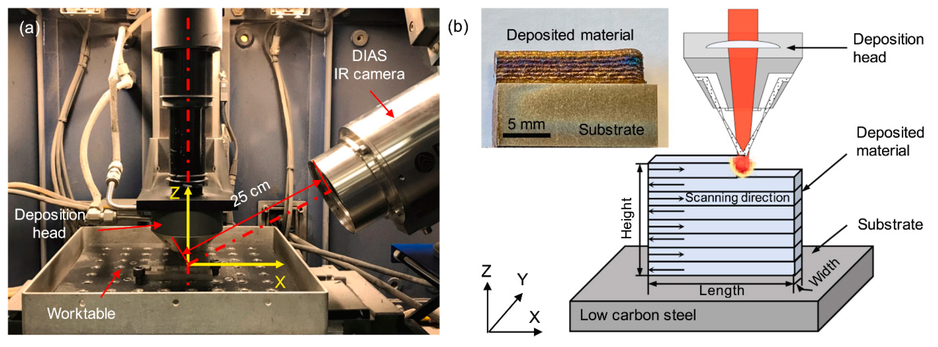
Figure 15.
(a) The experimental setup and (b) the schematics of the laser-engineered net shaping (LENS) process (reprinted with the permission from [78], Elsevier, 2020).
Figure 15.
(a) The experimental setup and (b) the schematics of the laser-engineered net shaping (LENS) process (reprinted with the permission from [78], Elsevier, 2020).

Figure 16.
XRD patterns of the top surface (15 mm for substrate) and near substrate (0.8 mm from substrate) of LENS processed Fe-based BMGs compared to NSSHS7574 starting powder, illustrating that the amorphous alloys have a mixture of amorphous and crystalline phases (reprinted with the permission from [80], Elsevier, 2010).

Figure 17.
Differential scanning calorimetry (DSC) curves of the feedstock powder and the 3D-printed NSSHS7574 alloy, depicting three crystallisation peaks with three-stage crystallisation behaviour, reprinted with the permission from [80], Elsevier, 2010 (Tg is glass transition temperature and Tx1, Tx2 and Tx3 are crystallisation temperatures, showing that the material undergoes a three-stage crystallisation process upon heating).

Figure 18.
Cross-sectional SEM micrographs of 3D-printed NSSHS7574 alloy (a) demonstrating exceptional interfacial bonding between substrate and the produced alloy (b) the microstructure at the top region of the bulk specimen (reprinted with the permission from [80], Elsevier, 2010).
Figure 18.
Cross-sectional SEM micrographs of 3D-printed NSSHS7574 alloy (a) demonstrating exceptional interfacial bonding between substrate and the produced alloy (b) the microstructure at the top region of the bulk specimen (reprinted with the permission from [80], Elsevier, 2010).

Figure 19.
Hardness of the LENS-processed Fe41Co7Cr15Mo14C15B6Y2 amorphous alloys as a function of laser energy density (LED) (A, B, C, D, E and F denote Fe41Co7Cr15Mo14C15B6Y2 samples that were produced using different laser parameters, i.e., laser energy density (LED). A and E have the same LED; however, for A, p = 300 W and v = 5 mm/s and for E, p = 600 W and v = 10 mm/s, for B: p = 600 W and v = 5 mm/s, for C: p = 900 W and v = 5 mm/s, for D: p = 300 W and v = 10 mm/s and for F: p = 900 W and v = 10 mm/s) (reprinted with the permission from [91], Springer, 2019).


Table 1.
Magnetic properties of amorphous alloys under direct current (DC) applications (reprinted with the permission from [30], CRC Press, 2016).
Table 1.
Magnetic properties of amorphous alloys under direct current (DC) applications (reprinted with the permission from [30], CRC Press, 2016).
| As Cast | Annealed | ||||||
|---|---|---|---|---|---|---|---|
| Alloy | Shape | Hc (A/m) | Mr/Ms | µmax (103) | Hc (A/m) | Mr/Ms | µmax (103) |
| Fe80B20 | Toroid | 6.4 | 0.51 | 100 | 3.2 | 0.77 | 300 |
| Fe40Ni40P14B6 | Toroid | 4.8 | 0.45 | 58 | 1.6 | 0.71 | 275 |
| Fe29Ni44P14B6Si2 | Toroid | 4.6 | 0.54 | 46 | 0.88 | 0.70 | 310 |
| Fe4.7Co70.3Si15B10 | Strip | 1.04 | 0.36 | 190 | 0.48 | 0.63 | 700 |
| (Fe0.8Ni0.2)78Si8B14 | Strip | 1.44 | 0.41 | 300 | 0.48 | 0.95 | 2000 |
| Fe80P16C3B | Toroid | 4.96 | 0.4 | 96 | 4.0 | 0.42 | 130 |
Table 2.
Coercivity of feedstock powder and melted samples of Fe71Si10C6Cr2 (at.%) alloy (reprinted with the permission from [76], Elsevier, 2019).
Table 2.
Coercivity of feedstock powder and melted samples of Fe71Si10C6Cr2 (at.%) alloy (reprinted with the permission from [76], Elsevier, 2019).
| Sample | Coercivity (A/m) |
|---|---|
| Powder | 99 |
| Melted once | 1032 |
| Melted twice | 397 |
| Melted twice and annealed | 238 |
Table 3.
Amorphous content, magnetic and mechanical properties of Fe-based alloys produced by laser additive manufacturing, also showing process parameters and powder size of starting powder.
Table 3.
Amorphous content, magnetic and mechanical properties of Fe-based alloys produced by laser additive manufacturing, also showing process parameters and powder size of starting powder.
| Process Parameters | Magnetic Properties | ||||||||
|---|---|---|---|---|---|---|---|---|---|
| Alloy | Powder Size (µm) | Technique | P (W) | v (m/s) | Amorphous Content (%) | Ms | Hc (A/m) | Hardness (HV) | Reference |
| Fe68.3C6.9 Si2.5B6.7P8.7Cr2.3Mo2.5Al2.1 | <150 | SLM | 340 | 1.5, 2.5 | Unknown | 102.8, 103.6 Am2/kg | 27.9 31.6 | - | [8] |
| FeCrMoCB | <80 | SLM | 80–200 | 0.8–5 | 100 a | - | - | 902 | [61] |
| Fe92.4Si3.1B4.5 | < 30 | SLM | 90 | 0.1–1.5 | 70–80 | 188.6–199 Am2/kg | 3485.5–5809.2 | 1654–2273 | [68] |
| Fe43.7Co7.3Cr14.7Mo12.6C15.5B4.3Y1.9 (at.%) | < 33 | SLM | 150–350 | 0.2–1 | 4.96–100 | - | - | - | [71] |
| Fe71Si10C6Cr2 (at.%) | ~24.5 | SLM | Max 120 | - | 89.6 | ~150 Am2/kg | 238 | - | [76] |
| Fe73.7Si11B11C2Cr2.28 | ~25 | SLM | 50, 70, 90 | 1.2, 1.6 | 47 | 1.22 T (kg/s2A) | 1591.5–2387.3 | - | [75] |
| Fe-Si-B-Nb-Cu | <150 | LENS | - | - | - | 118–150 Am2/kg | 1273.2–3819.7 | - | [5] |
| Cr<25Mo<15W<10C<3Mn<5Si<2B<5Febalance (at.%) | <180 | LENS | 250 | 0.02 | - | - | - | 1421 ± 101 | [80] |
| Fe41Co7Cr15Mo14C15B6Y2 (at.%) | - | LENS | 300, 600, 900 | 0.005, 0.01 | - | - | - | 1263.7 | [91] |
a According to the XRD analysis, the part is fully amorphous.
Publisher’s Note: MDPI stays neutral with regard to jurisdictional claims in published maps and institutional affiliations. |
© 2021 by the authors. Licensee MDPI, Basel, Switzerland. This article is an open access article distributed under the terms and conditions of the Creative Commons Attribution (CC BY) license (http://creativecommons.org/licenses/by/4.0/).
Share and Cite
MDPI and ACS Style
Ozden, M.G.; Morley, N.A. Laser Additive Manufacturing of Fe-Based Magnetic Amorphous Alloys. Magnetochemistry 2021, 7, 20. https://0-doi-org.brum.beds.ac.uk/10.3390/magnetochemistry7020020
AMA Style
Ozden MG, Morley NA. Laser Additive Manufacturing of Fe-Based Magnetic Amorphous Alloys. Magnetochemistry. 2021; 7(2):20. https://0-doi-org.brum.beds.ac.uk/10.3390/magnetochemistry7020020
Chicago/Turabian StyleOzden, Merve G., and Nicola A. Morley. 2021. "Laser Additive Manufacturing of Fe-Based Magnetic Amorphous Alloys" Magnetochemistry 7, no. 2: 20. https://0-doi-org.brum.beds.ac.uk/10.3390/magnetochemistry7020020
Note that from the first issue of 2016, this journal uses article numbers instead of page numbers. See further details here.