
Sodium-Based Chitosan Polymer Embedded with Copper Selenide (CuSe) Flexible Film for High Electromagnetic Interference (EMI) Shielding Efficiency

 , ,
, ,  , ,
, ,
Abstract
:1. Introduction
2. Methodology
2.1. Material
2.2. Cuse Synthesis
2.3. Film Fabrication
3. Characterization
4. Results and Discussion
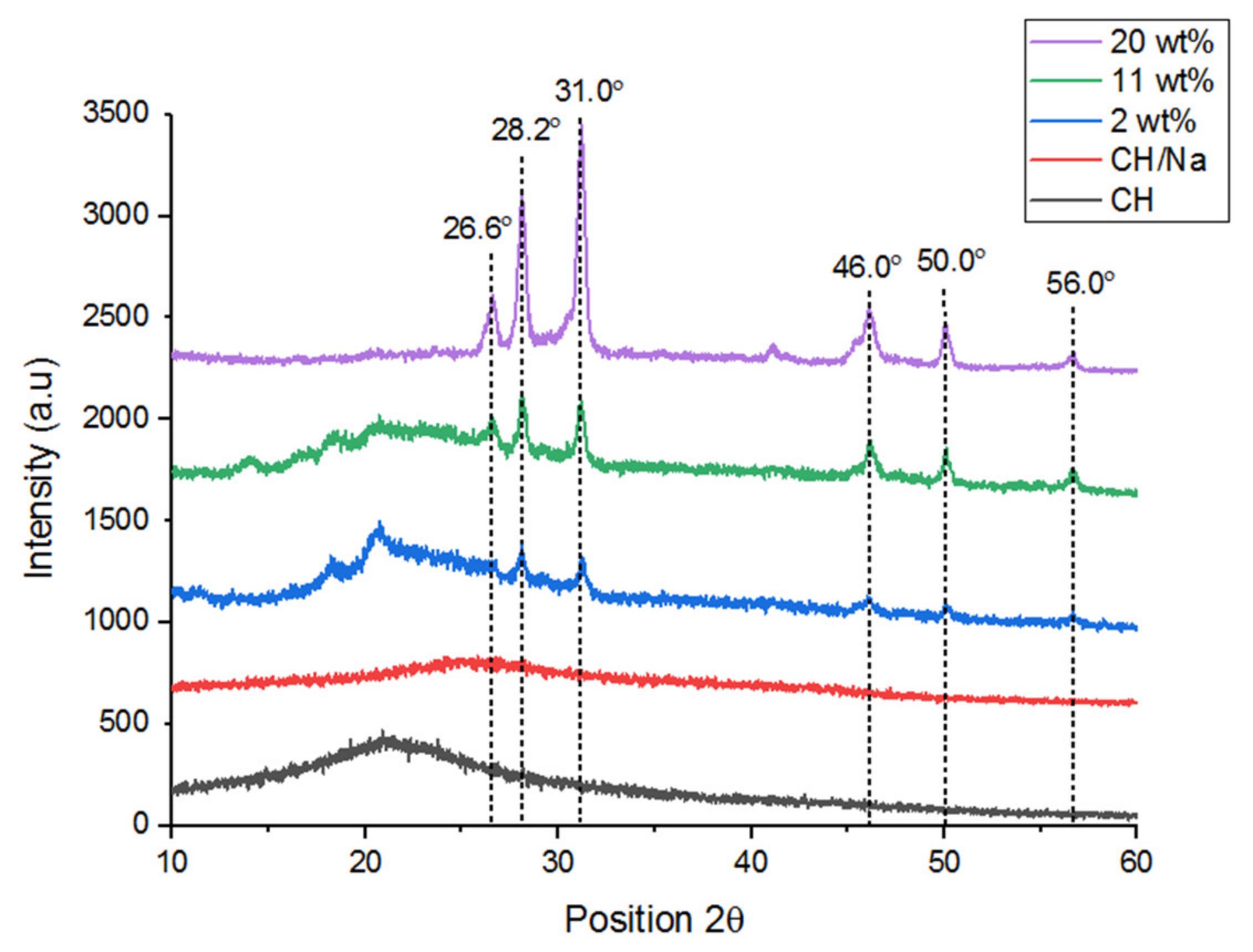
4.1. XRD
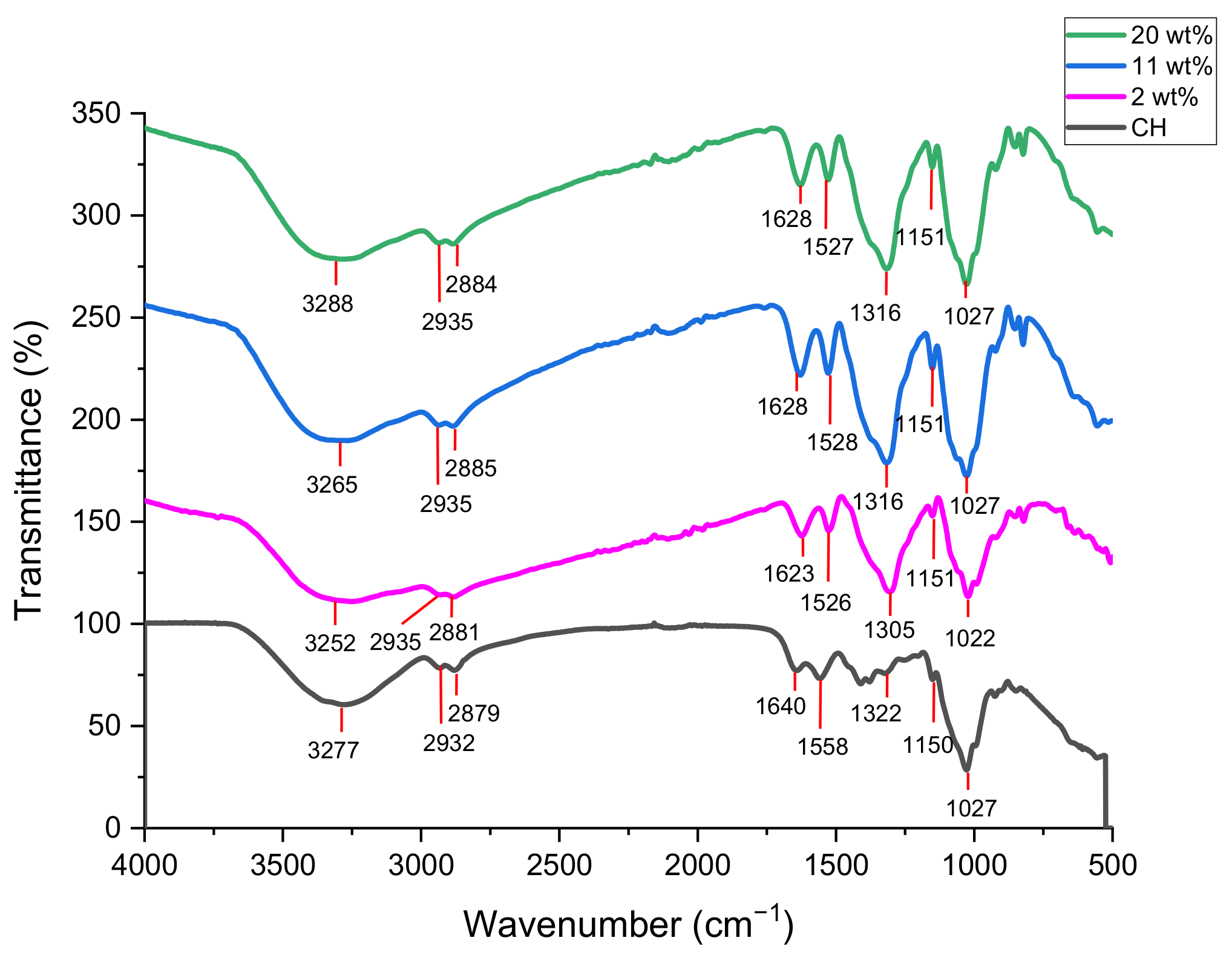
4.2. FTIR
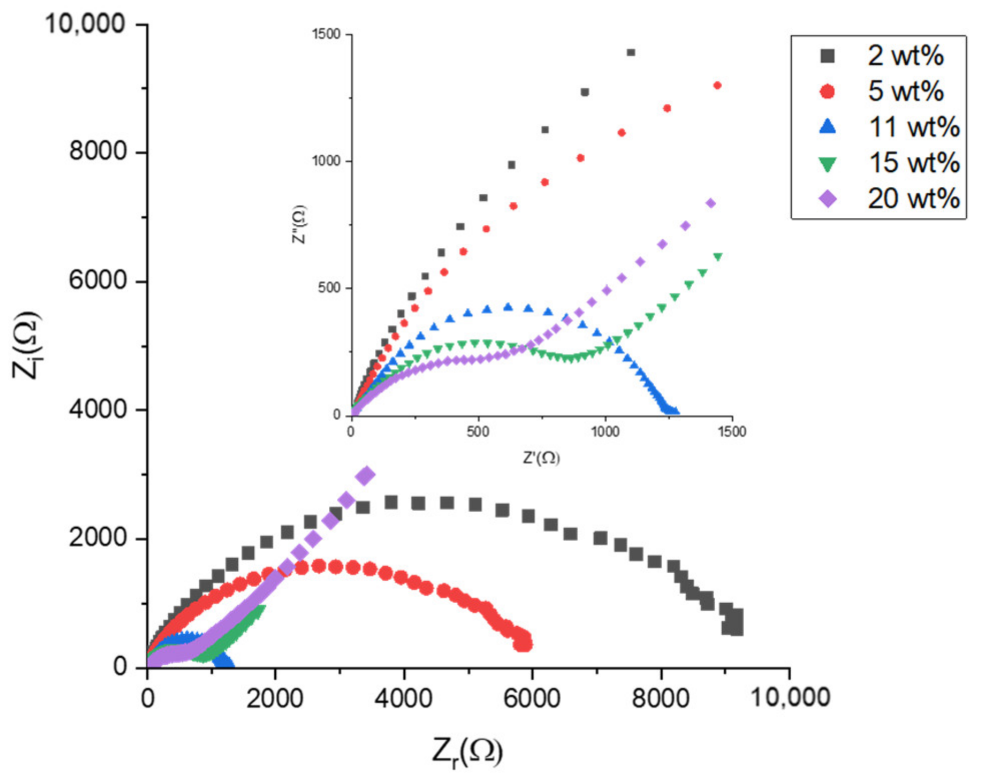
4.3. Impedance Spectroscopy Analysis
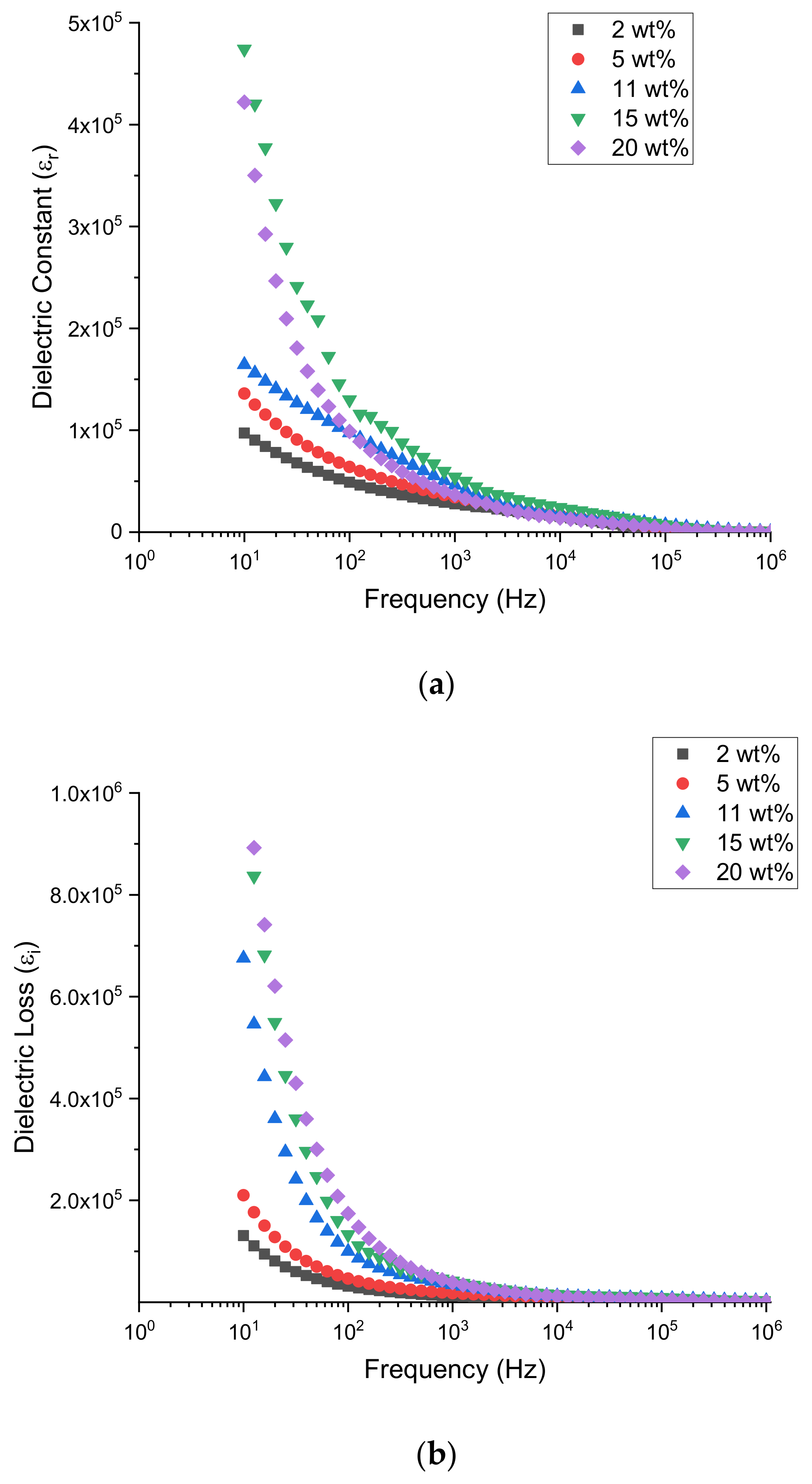
4.4. Dielectric Properties
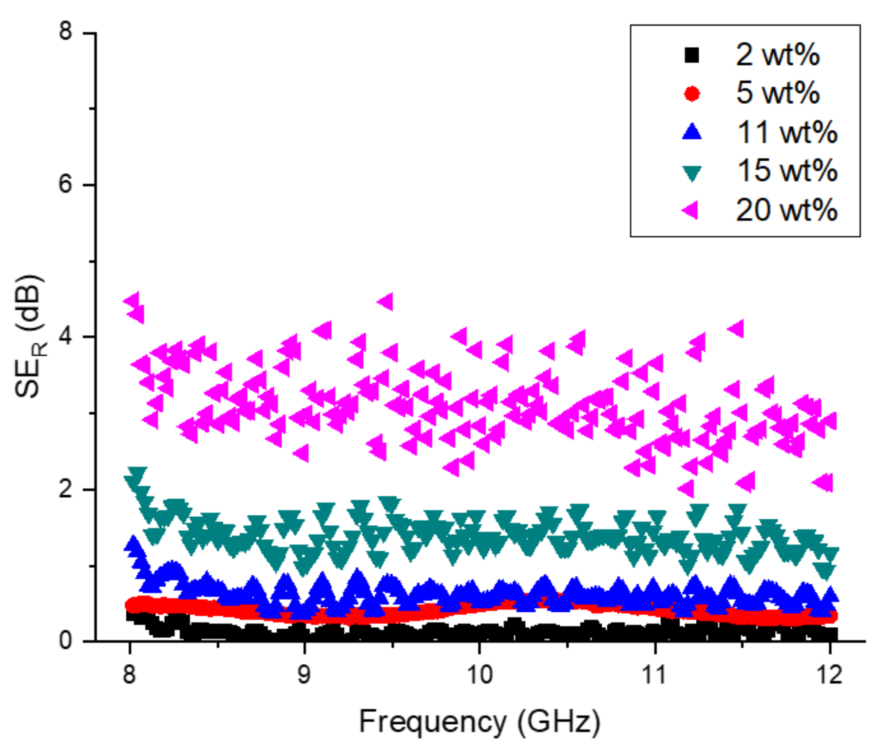
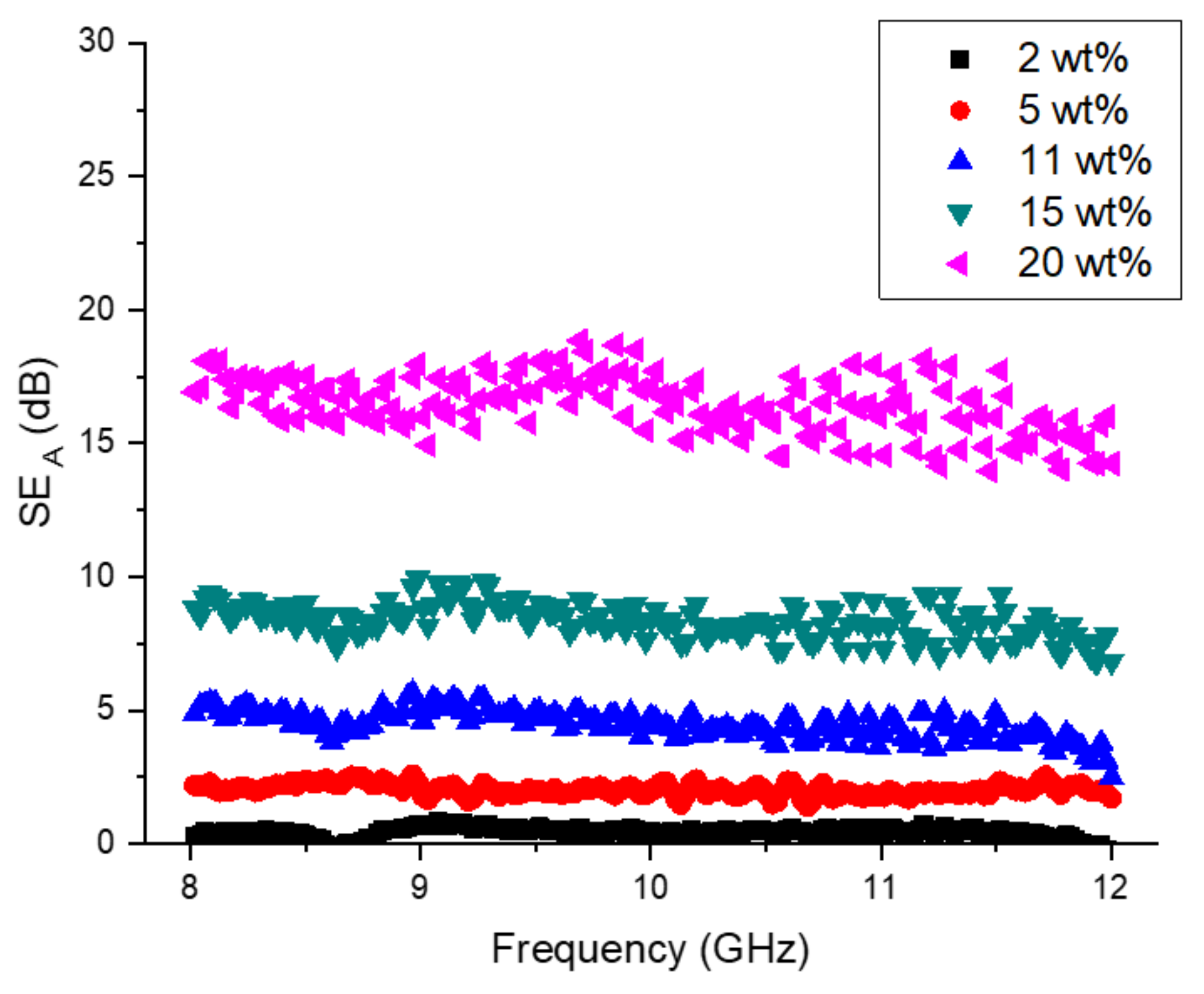
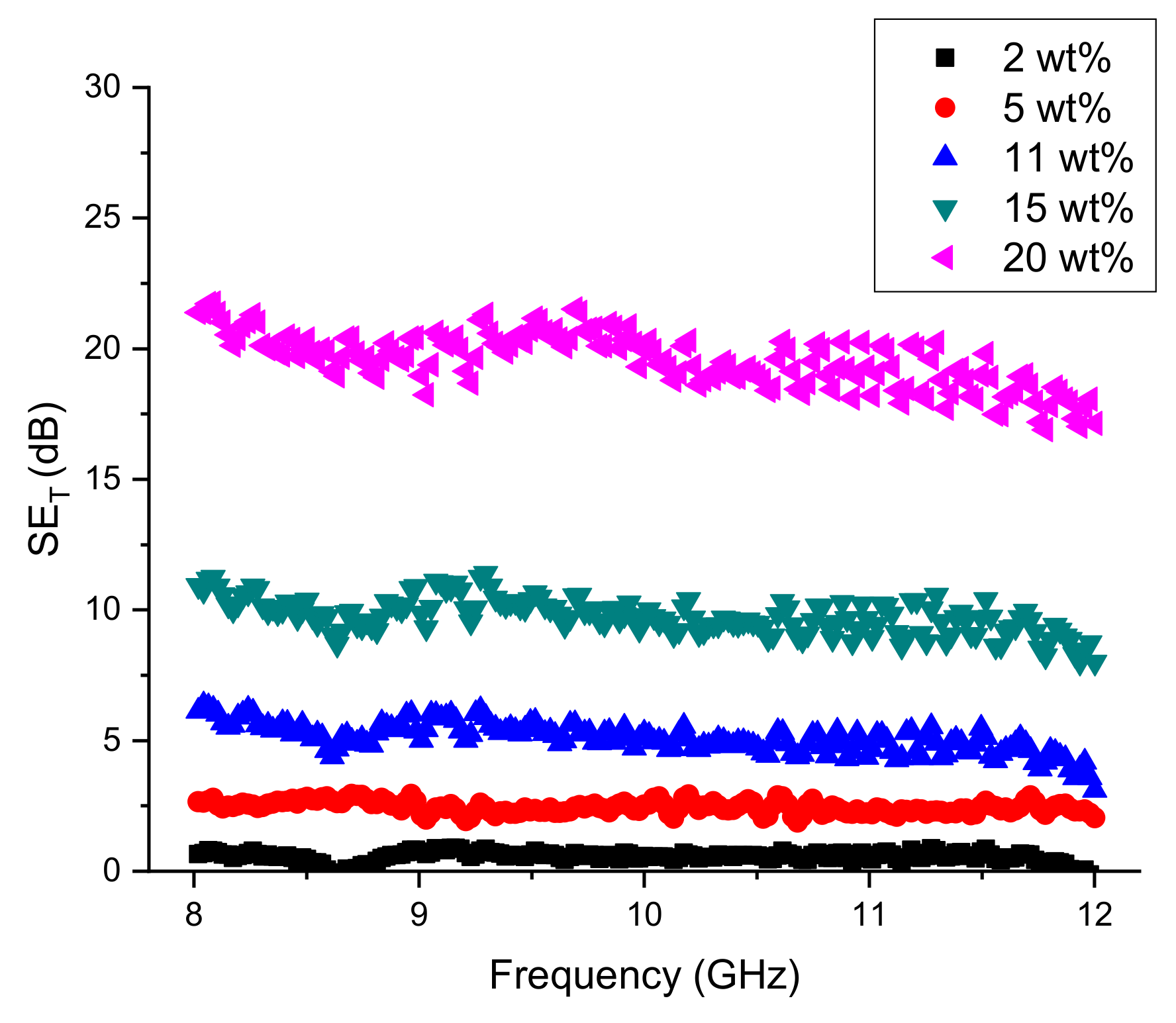
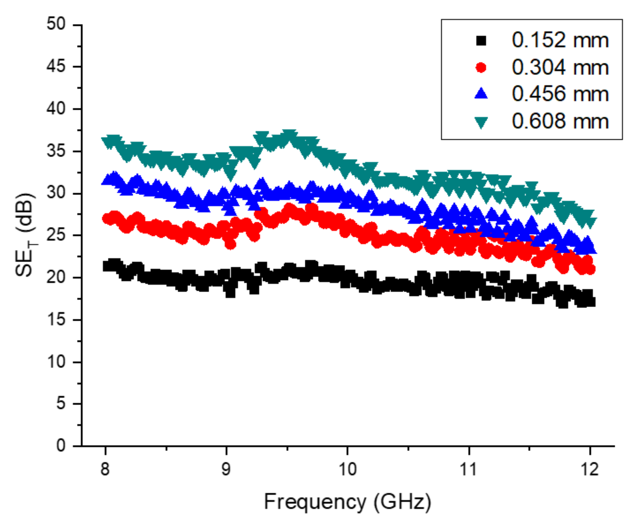
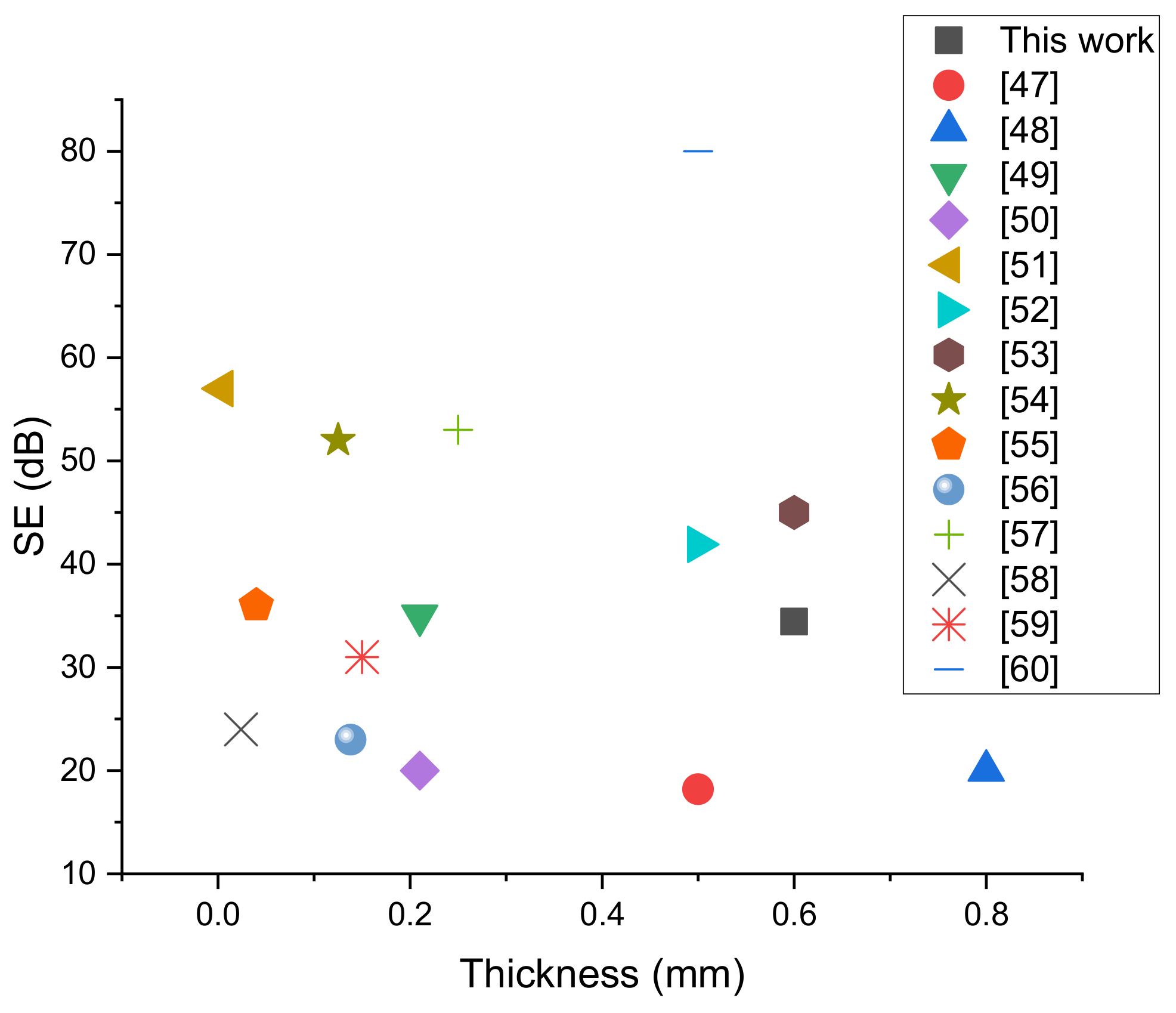
4.5. EMI Shielding Property
5. Conclusions
Author Contributions
Funding
Institutional Review Board Statement
Informed Consent Statement
Acknowledgments
Conflicts of Interest
References
- Sicard, E.; Dienot, J.M. Issues in electromagnetic compatibility of integrated circuits: Emission and susceptibility. Microelectron. Reliab. 2005, 45, 1277–1284. [Google Scholar] [CrossRef]
- Geetha, S.; Kumar, K.K.S.; Rao, C.R.K.; Vijayan, M.; Trivedi, D.C. EMI shielding: Methods and materials-A review. J. Appl. Polym. Sci. 2009, 112, 2073–2086. [Google Scholar] [CrossRef]
- Wang, K.; Ma, Q.; Zhang, Y.; Wang, S.; Han, G. Ag NPs-Assisted Synthesis of Stable Cu NPs on PET Fabrics for Antibacterial and Electromagnetic Shielding Performance. Polymers 2020, 12, 783. [Google Scholar] [CrossRef] [PubMed] [Green Version]
- Yang, K.; Periyasamy, A.P.; Venkataraman, M.; Militky, J.; Kremenakova, D.; Vecernik, J.; Pulíček, R. Resistance against Penetration of Electromagnetic Radiation for Ultra-light Cu/Ni-Coated Polyester Fibrous Materials. Polymers 2020, 12, 2029. [Google Scholar] [CrossRef] [PubMed]
- Kim, J.; Lee, S.; Kim, C.; Park, Y.; Kim, M.-H.; Seol, J.H. Electromagnetic Interference Shield of Highly Thermal-Conducting, Light-Weight, and Flexible Electrospun Nylon 66 Nanofiber-Silver Multi-Layer Film. Polymers 2020, 12, 1805. [Google Scholar] [CrossRef]
- Vyas, M.K.; Chandra, A. Ion-Electron-Conducting Polymer Composites: Promising Electromagnetic Interference Shielding Material. ACS Appl. Mater. Interfaces 2016, 8, 18450–18461. [Google Scholar] [CrossRef] [PubMed]
- Jiang, D.; Murugadoss, V.; Wang, Y.; Lin, J.; Ding, T.; Wang, Z.; Shao, Q.; Wang, C.; Liu, H.; Lu, N.; et al. Electromagnetic Interference Shielding Polymers and Nanocomposites—A Review. Polym. Rev. 2019, 59, 280–337. [Google Scholar] [CrossRef]
- Thirumavalavan, S.; Mani, K.; Sagadevan, S. A study of structural, morphological, optical and electrical properties of Zinc Selenide (ZnSe) thin film. Mater. Today Proc. 2016, 3, 2305–2314. [Google Scholar] [CrossRef]
- Bari, R.H.; Ganesan, V.; Potadar, S.; Patil, L.A. Structural, Optical and Electrical Properties of Chemically Deposited Copper Selenide Films. Bull. Mater. Sci. 2009, 32, 37. [Google Scholar] [CrossRef] [Green Version]
- Xiao, G.; Ning, J.; Liu, Z.; Sui, Y.; Wang, Y.; Dong, Q.; Tian, W.; Liu, B.; Zou, G.; Zou, B. Solution synthesis of copper selenide nanocrystals and their electrical transport properties. CrystEngComm 2012, 14, 2139–2144. [Google Scholar] [CrossRef]
- Heyding, R.D. The Copper/Selenium System. Can. J. Chem. 1966, 44, 1233–1236. [Google Scholar] [CrossRef]
- Al-Mamun; Islam, A.B.M.O.; Bhuiyan, A.H. Structural, electrical and optical properties of copper selenide thin films deposited by chemical bath deposition technique. J. Mater. Sci. Mater. Electron. 2005, 16, 263–268. [Google Scholar] [CrossRef] [Green Version]
- Pejova, B.; Grozdanov, I. Chemical Deposition and Characterization of Cu3Se2 and CuSe Thin Films. J. Solid State Chem. 2001, 158, 49–54. [Google Scholar] [CrossRef]
- Nelson, P.I.; Arthi, R.; Kannan, R.R.; Selvan, T.P.; Ajitha, E.; Ashina, A.; Vidhya, B. Influence of heat treatment on the properties of thermally evaporated copper selenide thin films. Mater. Lett. 2018, 223, 14–16. [Google Scholar] [CrossRef]
- Zhang, A.Y.; Ma, Q.A.; Wang, Z.G.; Luü, M.K.; Yang, P.; Zhou, G.J. Controllable synthesis of copper selenide nanocrystals through a green paraffin-acetate method. Mater. Chem. Phys. 2010, 124, 916–921. [Google Scholar] [CrossRef]
- Wu, Y.; Korolkov, I.; Qiao, X.; Zhang, X.; Wan, J.; Fan, X. Facile synthesis of CuSe nanoparticles and high-quality single-crystal two-dimensional hexagonal nanoplatelets with tunable near-infrared optical absorption. J. Solid State Chem. 2016, 238, 279–283. [Google Scholar] [CrossRef]
- Kaur, H.; Kaur, J.; Singh, L. Influence of different deposition potential on the structural and optical properties of copper selenide nanowires. Superlattices Microstruct. 2016, 97, 85–93. [Google Scholar] [CrossRef]
- Mansour, B.; Zawawi, I.; Elsayed-Ali, H.E.; Hameed, T.A. Preparation and characterization of optical and electrical properties of copper selenide sulfide polycrystalline thin films. J. Alloy. Compd. 2017, 740, 1125–1132. [Google Scholar] [CrossRef]
- Wang, W.; Geng, Y.; Qian, Y.; Wang, C.; Liu, X. A convenient, low temperature route to nanocrystalline SnSe. Mater. Res. Bull. 1999, 34, 403–406. [Google Scholar] [CrossRef]
- Liew, J.Y.; Talib, Z.A.; Zainal, Z.; Kamarudin, M.A.; Osman, N.H.; Lee, H.K. Structural and transport mechanism studies of copper selenide nanoparticles. Semicond. Sci. Technol. 2019, 34, 125017. [Google Scholar] [CrossRef]
- Wang, C.-Y.; He, H.-X. Tunable optical and magnetic properties of Ni-doped CuSe nanowires using an anodic aluminum oxide template assisted hydraulic method. Nanotechnology 2019, 30, 315704. [Google Scholar] [CrossRef]
- Shukla, S.K.; Mishra, A.K.; Arotiba, O.A.; Mamba, B.B. Chitosan-based nanomaterials: A state-of-the-art review. Int. J. Biol. Macromol. 2013, 59, 46–58. [Google Scholar] [CrossRef]
- Osman, N.H.; Mazu, N.N.; Chyi, J.L.Y.; Ramli, M.M.; Majid, M.A.H.M.A.; Mazlan, H.I. Chitosan-Bentonite Crosslinked Film As Indicator for Copper (II) Ions Adsorption. Eur. Phys. J. Appl. Phys. 2021. [Google Scholar] [CrossRef]
- Aziz, S.B.; Abdullah, O.G.; Rasheed, M.A.; Ahmed, H.M. Effect of High Salt Concentration (HSC) on Structural, Morphological, and Electrical Characteristics of Chitosan Based Solid Polymer Electrolytes. Polymers 2017, 9, 187. [Google Scholar] [CrossRef] [Green Version]
- Aziz, S.B.; Brza, M.; Mohamed, P.A.; Kadir, M.; Hamsan, M.H.; Abdulwahid, R.; Woo, H. Increase of metallic silver nanoparticles in Chitosan: AgNt based polymer electrolytes incorporated with alumina filler. Results Phys. 2019, 13, 102326. [Google Scholar] [CrossRef]
- Asnawi, A.S.F.M.; Aziz, S.B.; Nofal, M.M.; Hamsan, M.H.; Brza, M.A.; Yusof, Y.M.; Abdilwahid, R.T.; Muzakir, S.K.; Kadir, M.F.Z. Glycerolized Li+ Ion Conducting Chitosan-Based Polymer Electrolyte for Energy Storage EDLC Device Applications with Relatively High Energy Density. Polymers 2020, 12, 1433. [Google Scholar] [CrossRef]
- Bandara, T.M.W.J.; Mellander, B.E. Evaluation of Mobility, Diffusion Coefficient and Density of Charge Carriers in Ionic Liquids and Novel Electrolytes Based on a New Model for Dielectric Response. In Ionic Liquids: Theory, Properties, New Approaches; IntechOpen: London, UK, 2011; pp. 383–406. [Google Scholar]
- Sebastian, M.T.; Ubic, R.; Jantunen, H. Microwave Materials and Applications, 1st ed.; John Wiley & Sons: New York, NY, USA, 2017; pp. 575–672. [Google Scholar]
- Yahya, M.Z.A.; Arof, A.K. Studies on lithium acetate doped chitosan conducting polymer system. Eur. Polym. J. 2002, 38, 1191–1197. [Google Scholar] [CrossRef]
- Raagulan, K.; Braveenth, R.; Kim, B.M.; Lim, K.J.; Lee, S.B.; Kim, M.; Chai, K.Y. An effective utilization of MXene and its effect on electromagnetic interference shielding: Flexible, free-standing and thermally conductive composite from MXene–PAT–poly(p-aminophenol)–polyaniline co-polymer. RSC Adv. 2020, 10, 1613–1633. [Google Scholar] [CrossRef] [Green Version]
- Sankaran, S.; Deshmukh, K.; Ahamed, M.B.; Pasha, S.K. Recent advances in electromagnetic interference shielding properties of metal and carbon filler reinforced flexible polymer composites: A review. Compos. Part A Appl. Sci. Manuf. 2018, 114, 49–71. [Google Scholar] [CrossRef]
- Yamaguchi, I.; Tokuchi, K.; Fukuzaki, H.; Koyama, Y.; Takakuda, K.; Monma, H. Preparation and Microstructure Analysis of Chitosan/Hydroxyapatite Nanocomposites. J. Biomed. Mater. Res. 2001, 55, 20–27. [Google Scholar] [CrossRef]
- Nugraheni, P.S.; Soeriyadi, A.H.; Sediawan, W.B.; Budhijanto, W. Influence of Salt Addition and Freezing-Thawing on Particle Size and Zeta Potential of Nano-Chitosan. In Proceedings of the IOP Conference Series: Earth and Environmental Science, Bogor, Indonesia, 9–10 October 2018; Volume 278. [Google Scholar]
- Bhargav, P.B.; Mohan, V.M.; Sharma, A.K.; Rao, V.V.R.N. Structural and electrical studies of sodium iodide doped poly(vinyl alcohol) polymer electrolyte films for their application in electrochemical cells. Ionics 2007, 13, 173–178. [Google Scholar] [CrossRef]
- Martinez-Cisneros, C.; Levenfeld, B.; Varez, A.; Sanchez, J. Development of sodium-conducting polymer electrolytes: Comparison between film-casting and films obtained via green processes. Electrochim. Acta 2016, 192, 456–466. [Google Scholar] [CrossRef]
- Chandrasakaran, D.S.; Nainggolan, I.; Ikhsan, T.; Derman, N. Ammonia Gas Sensor Based on Chitosan Biopolymer. Mater. Sci. Forum 2015, 819, 429–434. [Google Scholar] [CrossRef]
- Yadi, M.G.; Benguella, B.; Gaouar-Benyelles, N.; Tizaoui, K. Adsorption of ammonia from wastewater using low-cost bentonite/chitosan beads. Desalination Water Treat. 2016, 57, 21444–21454. [Google Scholar] [CrossRef]
- Haseena, P.; Padmavathy, K.; Krishnan, P.R.; Madhu, G. Adsorption of Ammonium Nitrogen from Aqueous Systems Using Chitosan-Bentonite Film Composite. Procedia Technol. 2016, 24, 733–740. [Google Scholar] [CrossRef] [Green Version]
- Muthukannan, A.; Sivakumar, G.; Mohanraj, K. Influence of Equimolar Concentration on Structural and Optical Properties of Binary Selenides Nanoparticles. Part. Sci. Technol. 2014, 32, 392–398. [Google Scholar] [CrossRef]
- Aziz, S.B.; Woo, T.J.; Kadir, M.F.Z.; Ahmed, H.M. A conceptual review on polymer electrolytes and ion transport models. J. Sci. Adv. Mater. Devices 2018, 3, 1–17. [Google Scholar] [CrossRef]
- Mamunya, Y.; Davidenko, V.V.; Lebedev, É.V. Percolation conductivity of polymer composites filled with dispersed conductive filler. Polym. Compos. 1995, 16, 319–324. [Google Scholar] [CrossRef]
- Elmezayyen, A.S.; Reicha, F.M. Preparation of Chitosan Copper Complexes: Molecular Dynamic Studies of Chitosan and Chitosan Copper Complexes. Open J. Appl. Sci. 2015, 5, 415–427. [Google Scholar] [CrossRef] [Green Version]
- Rayssi, C.; El.Kossi, S.; Dhahri, J.; Khirouni, K. Frequency and temperature-dependence of dielectric permittivity and electric modulus studies of the solid solution Ca0.85Er0.1Ti1-xCo4x/3O3 (0 ≤ x ≤ 0.1). RSC Adv. 2018, 8, 17139–17150. [Google Scholar] [CrossRef] [Green Version]
- Yusof, Y.M.; Illias, H.A.; Kadir, M.F.Z. Incorporation of NH4Br in PVA-chitosan blend-based polymer electrolyte and its effect on the conductivity and other electrical properties. Ionics 2014, 20, 1235–1245. [Google Scholar] [CrossRef]
- Khiar, A.S.A.; Puteh, R.; Arof, A. Conductivity studies of a chitosan-based polymer electrolyte. Phys. B Condens. Matter 2006, 373, 23–27. [Google Scholar] [CrossRef]
- Cao, L.; Sendur, K. Surface Roughness Effects on the Broadband Reflection for Refractory Metals and Polar Dielectrics. Materials 2019, 12, 3090. [Google Scholar] [CrossRef] [Green Version]
- Yang, H.; Yu, Z.; Wu, P.; Zou, H.; Liu, P. Electromagnetic interference shielding effectiveness of microcellular polyimide/In Situ thermally reduced graphene oxide/carbon nanotubes nanocomposites. Appl. Surf. Sci. 2018, 434, 318–325. [Google Scholar] [CrossRef]
- Li, Y.; Pei, X.; Shen, B.; Zhai, W.; Zhang, L.; Zheng, W. Polyimide/graphene composite foam sheets with ultrahigh thermostability for electromagnetic interference shielding. RSC Adv. 2015, 5, 24342–24351. [Google Scholar] [CrossRef]
- Al-Saleh, M.; Gelves, G.A.; Sundararaj, U. Copper nanowire/polystyrene nanocomposites: Lower percolation threshold and higher EMI shielding. Compos. Part A Appl. Sci. Manuf. 2011, 42, 92–97. [Google Scholar] [CrossRef]
- Gelves, G.A.; Al-Saleh, M.; Sundararaj, U. Highly electrically conductive and high performance EMI shielding nanowire/polymer nanocomposites by miscible mixing and precipitation. J. Mater. Chem. 2011, 21, 829–836. [Google Scholar] [CrossRef]
- Shahzad, F.; Alhabeb, M.; Hatter, C.B.; Anasori, B.; Hong, S.M.; Koo, C.M.; Gogotsi, Y. Electromagnetic interference shielding with 2D transition metal carbides (MXenes). Science 2016, 353, 1137–1140. [Google Scholar] [CrossRef] [Green Version]
- Singh, R.; Kulkarni, S.G. Nanocomposites based on transition metal oxides in polyvinyl alcohol for EMI shielding application. Polym. Bull. 2013, 71, 497–513. [Google Scholar] [CrossRef]
- Anupama, J.; Anil, B.; Rajvinder, S.; Alegaonkar, P.S.; Balasubramanian, K.; Suwarna, D. Graphene Nanoribbon–PVA Composite as EMI Shielding Material in the X band. Nanotechnology 2013, 24, 455705. [Google Scholar]
- Wan, Y.-J.; Zhu, P.-L.; Yu, S.-H.; Sun, R.; Wong, C.-P.; Liao, W.-H. Graphene paper for exceptional EMI shielding performance using large-sized graphene oxide sheets and doping strategy. Carbon 2017, 122, 74–81. [Google Scholar] [CrossRef]
- Zhang, Y.; Wang, L.; Zhang, J.; Song, P.; Xiao, Z.; Liang, C.; Qiu, H.; Kong, J.; Gu, J. Fabrication and investigation on the ultra-thin and flexible Ti3C2Tx/co-doped polyaniline electromagnetic interference shielding composite films. Compos. Sci. Technol. 2019, 183, 107833. [Google Scholar] [CrossRef]
- Parit, M.; Du, H.; Zhang, X.; Prather, C.; Adams, M.; Jiang, Z. Polypyrrole and cellulose nanofiber based composite films with improved physical and electrical properties for electromagnetic shielding applications. Carbohydr. Polym. 2020, 240, 116304. [Google Scholar] [CrossRef] [PubMed]
- Zahid, M.; Nawab, Y.; Gulzar, N.; Rehan, Z.A.; Shakir, M.F.; Afzal, A.; Rashid, I.A.; Tariq, A. Fabrication of reduced graphene oxide (RGO) and nanocomposite with thermoplastic polyurethane (TPU) for EMI shielding application. J. Mater. Sci. Mater. Electron. 2010, 31, 967–974. [Google Scholar] [CrossRef]
- Li, Y.; Shen, B.; Pei, X.; Zhang, Y.; Yi, D.; Zhai, W.; Zhang, L.; Wei, X.; Zheng, W. Ultrathin carbon foams for effective electromagnetic interference shielding. Carbon 2016, 100, 375–385. [Google Scholar] [CrossRef]
- Chaudhary, A.; Kumari, S.; Kumar, R.; Teotia, S.; Singh, B.P.; Singh, A.P.; Dhawan, S.K.; Dhakate, S.R. Lightweight and Easily Foldable MCMB-MWCNTs Composite Paper with Exceptional Electromagnetic Interference Shielding. ACS Appl. Mater. Interfaces 2016, 8, 10600–10608. [Google Scholar] [CrossRef]
- Chaudhary, A.; Kumar, R.; Teotia, S.; Dhawan, S.K.; Dhakate, S.R.; Kumari, S. Integration of MCMBs/MWCNTs with Fe3O4 in a flexible and light weight composite paper for promising EMI shielding applications. J. Mater. Chem. C 2016, 5, 322–332. [Google Scholar] [CrossRef]


| CuSe (wt%) | Film Thickness (mm) | Bulk Resistance, RB (Ω) | Conductivity, σ (S/cm) |
|---|---|---|---|
| 2 | 0.119 | 10,123.0 | 3.74 × 10⁻⁷ |
| 5 | 0.125 | 6575.1 | 6.05 × 10⁻⁷ |
| 11 | 0.132 | 1265.8 | 3.32 × 10⁻⁶ |
| 15 | 0.142 | 816.61 | 5.54 × 10⁻⁶ |
| 20 | 0.152 | 442.18 | 3.69 × 10⁻⁵ |
Publisher’s Note: MDPI stays neutral with regard to jurisdictional claims in published maps and institutional affiliations. |
© 2021 by the authors. Licensee MDPI, Basel, Switzerland. This article is an open access article distributed under the terms and conditions of the Creative Commons Attribution (CC BY) license (https://creativecommons.org/licenses/by/4.0/).
Share and Cite
Osman, N.H.; Mazu, N.N.; Ying Chyi Liew, J.; Ramli, M.M.; Sandu, A.V.; Nabiałek, M.; Abdull Majid, M.A.H.M.; Mazlan, H.I. Sodium-Based Chitosan Polymer Embedded with Copper Selenide (CuSe) Flexible Film for High Electromagnetic Interference (EMI) Shielding Efficiency. Magnetochemistry 2021, 7, 102. https://0-doi-org.brum.beds.ac.uk/10.3390/magnetochemistry7070102
Osman NH, Mazu NN, Ying Chyi Liew J, Ramli MM, Sandu AV, Nabiałek M, Abdull Majid MAHM, Mazlan HI. Sodium-Based Chitosan Polymer Embedded with Copper Selenide (CuSe) Flexible Film for High Electromagnetic Interference (EMI) Shielding Efficiency. Magnetochemistry. 2021; 7(7):102. https://0-doi-org.brum.beds.ac.uk/10.3390/magnetochemistry7070102
Chicago/Turabian StyleOsman, Nurul Huda, Nurul Najiha Mazu, Josephine Ying Chyi Liew, Muhammad Mahyiddin Ramli, Andrei Victor Sandu, Marcin Nabiałek, Mohammad Abdull Halim Mohd Abdull Majid, and Hazeem Ikhwan Mazlan. 2021. "Sodium-Based Chitosan Polymer Embedded with Copper Selenide (CuSe) Flexible Film for High Electromagnetic Interference (EMI) Shielding Efficiency" Magnetochemistry 7, no. 7: 102. https://0-doi-org.brum.beds.ac.uk/10.3390/magnetochemistry7070102