Review

Overview of Optical Digital Measuring Challenges and Technologies in Laser Welded Components in EV Battery Module Design and Manufacturing

1
Department of Mechanical Engineering, Turku University of Applied Sciences, Joukahaisenkatu 3, FIN-20520 Turku, Finland
2
Machine Technology Center Turku Ltd., Lemminkäisenkatu 28, FIN-20520 Turku, Finland
3
Department of Mechanical Engineering, University of Turku, FI-20014 Turku, Finland
4
Research Group of Laser Material Processing and Additive Manufacturing, School of Energy Systems, LUT University, FI-53851 Lappeenranta, Finland
5
Valmet Automotive, Autotehtaankatu 14, FIN-23500 Uusikaupunki, Finland
*
Author to whom correspondence should be addressed.
Submission received: 6 August 2020 / Revised: 4 September 2020 / Accepted: 11 September 2020 / Published: 16 September 2020
(This article belongs to the Special Issue Batteries and Electric Vehicles)

Abstract

:
Ensuring the precision and repeatability of component assembly in the production of electric vehicle (EV) battery modules requires fast and accurate measuring methods. The durability of EV battery packs depends on the quality of welded connections, therefore exact positioning of the module components is critical for ensuring safety in exploitation. Laser welding is a non-contact process capable of welding dissimilar materials with high precision, for that reason it has become the preferred joining method in battery production. In high volume manufacturing, one of the main production challenges is reducing the time required for assessment of dimensional and geometrical accuracy prior to joining. This paper reviews the challenges of EV battery design and manufacturing and discusses commercially available scanner-based measurement systems suitable for fabrication of battery pack components. Versatility of novel metrological systems creates new opportunities for increasing the production speed, quality and safety of EV battery modules.

1. Introduction

Modern electrified vehicles (EV), both full and hybrid models, are gaining popularity because of market pull and technology push for e-mobility. The main efforts in the popularization of electric drivetrain technology have been concentrated on developing batteries with higher energy density and expansion of charging infrastructure [1]. Present day electric vehicles are powered by battery packs using lithium-ion technology, which are widely used in consumer electronics. Innovations in battery cell technology have made electrically powered cars affordable for personal use, whereas applications for long distant transport are restricted because of the power of batteries and the availability of the fast charging points being limited. Governmental authorities have been tightening emission regulations to decrease the environmental impact of transportation through the wider use of renewable energy sources. Regional targets for emission reductions of passenger vehicles have been summarized by [2,3]. Global governmental strategies and policies to support the efforts of the automotive industry in developing more efficient and customer friendly EVs and hybrid solutions have been outlined in [4,5]. An extensive comparison study of four EV battery types (Na-NiCl2, Li-S, Ni-MH and Li-Ion) examining performance through modelling and simulation on a virtual track, showed that Li-ion batteries currently outperform alternatives in cost efficiency and, service lifetime [6]. Comparing lead-acid or nickel-metal-hybrid chemistries and Li-ion technology, Li-ion systems provide higher performance at lower weight and smaller size [7]. The applicability of different battery compositions in state-of-the-art analysis of EV market trends has been summarized in [8]. It is probable that Li-ion technology replaces the standard lead-acid start-stop batteries in the near future [9].
Energy storage systems of EVs have a modular design and consist of single battery cells that are joined into modules which are then stacked to form a battery pack (see Figure 1). The pack build and design of mechanical connections between the cells and rail has an effect on the rigidness, performance, and aging of the unit.
The modules are formed by stacking battery cells and connecting the terminals with busbars by laser welding [10]. Modular architecture ensures the durability of the battery pack and is needed to meet critical performance requirements: prevention of thermal runaway, vibration isolation and crash protection. Positioning accuracy of the components during pack assembly is a key factor determining the quality of connections [11,12,13,14,15]. Quality of the welded joint is strongly dependent on the precision of the module geometry, any dimensional deviations compromise the integrity of the pack and cause safety issues due to the weakened vibration and crash force resistance [16].
In practice, battery welding is a high-volume production process with narrow time windows for assembly and measurement operations in production line. In a comprehensive review discussing methods for increasing manufacturing speed, metrology is acknowledged to be one of the three main production bottle-necks, next to hindrances originating from material processing and co-ordination of the work flow [17]. Another issue is tool wear of instruments that rely on a physical contact for position validation. Tool wear complicates the process and requires periodic maintenance thereby lowering overall productivity. For accelerating the production, establishing internal decision points (quality gates) has been proposed, where measurement steps are aggregated and data of intermediate quality verifications are collected [18].
As an alternative, advanced contactless measuring techniques can be considered [19]. In addition to detecting joint position, optical measuring visualizes gap size and incidence angle prior to welding, thereby enabling to compensate for them on-line. In sheet metal forming, near- or in-line measurement systems are already outperforming the contact measuring methods in registering differences caused by shrinkage and bending [20,21]. Quality inspection time can be reduced by 23.8% through optimization of the viewpoint sampling coverage path planning in single-sided quality inspection of free-form surfaces [20]. The main issue impeding the widespread industrial application of camera-based solutions has so far been the lack of computation power required for processing the acquired data quickly enough. However, with attention to technological innovations and recent developments in computer vision and machine learning, optical measuring techniques have the potential to outperform the previous techniques in both, speed and accuracy.
This review paper concentrates on flexible, fast and accurate non-contact measuring methods for laser joining processes in high-volume, high-quality manufacturing of safe, durable battery packs. Numerous battery module and pack designs are currently employed in industrial production, this study examines on-line optical measuring solutions applicable for these designs. The accuracy of advanced measurement methods and devices suitable for the on-line monitoring of intermediate assemblies and laser welding during serial manufacturing are compared.

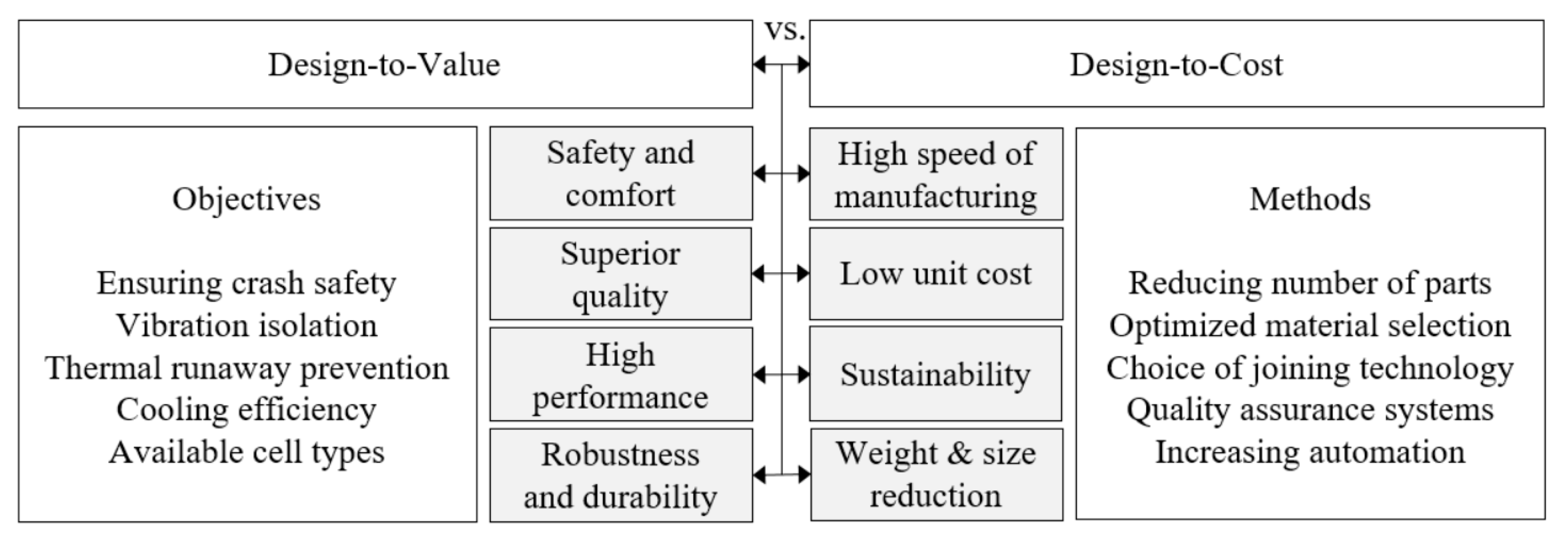
2. EV Battery Design Principles

The battery module consists of multiple cells located at a constant distance from each other to ensure cooling and prevent overheating [22]. EV battery packs contain multiple battery cells, a modular structure is needed because of the electrochemical properties of the elements. The cells are stacked using metal or plastic support structures to leave space for state-of-charge dependent swelling. The structure is typically consolidated by gluing cells together and/or enclosing the cells in a metal frame [23]. EV battery design guidelines are at times controversial [12]. Structure should be as lightweight and durable as possible, therefore suggesting the use of lightweight metal alloy or carbon fiber materials. As a consequence of stringent requirements for the safety of the final product, design and manufacturing methods for battery pack production involve a trade-off between simplicity and accuracy. As an example of existing solutions, Figure 2 shows some of the conflicting requirements influencing the design process. Requirements imposed on batteries are specific to the field of application, yet ensuring structural integrity for guaranteeing thermal stability and safety in service is of upmost importance.
Commercially available lithium-ion battery cells can be divided based on their structure and appearance into cylindrical and prismatic cells. Cylindrical cells are hard-case cells, while prismatic cells can either be hard-case rectangular prisms or so-called pouch cells with a soft, bag-like structure. Specifics of manufacturing process of different builds of lithium-ion battery cells with focus on the efficiency of the production cycle showed that limitations of pick-and-place assembly are described as the main bottleneck in automotive production [24]. Figure 3 shows different commercially available cell types and their module designs with the suitability of different joining methods of electrical contacts.
Terminals of each battery cell are connected with busbars to create an electrical circuit of series and parallel connections leading to the desired voltage level of the module [22]. Regardless of the cell type, increased energy density in commercially available battery chemistries tends to lead to a higher risk of unstable behavior such as thermal runaway [25]. Thermal runaway is an exothermic chain reaction where self-heating of the battery exceeds a certain limit [26]. Thermal runaway is caused by either mechanical, electrical or thermal abuse that leads to overheating and deterioration of internal structures and adjacent cells of the pack. The risk is minimized by choosing optimized materials, imposing thermal barriers to limit the progress of the reaction, and including a point of egress to channel the heat out of the battery pack. The individual performance of each cell and of the arrangement of cells inside the pack should be as uniform as possible to avoid uneven temperature distribution [27]. Vibrations inside the battery pack may cause electric connections to loosen, or even breakage of support structures that hold the cells in place acting as channels of the cooling system. Unequal intercell connections at the pack level cause imbalanced currents, which, in turn, lead to uneven heat generation in the battery packs when subjected to dynamic loading [28]. High variation of battery cells within a module affects its performance and limits the capacity of the battery to that of the weakest cell within the module [29].

3. Overview of Challenges in Digital Measuring

Designing the assembly of battery modules in a way that measuring is easy and fast, is a challenging task when contact measure methods like the coordinate measuring machine (CMM) are used. The ability to conduct on-line measurement is a key consideration in product design and critical to efficient production. In some cases, compliance with allowable tolerances requires changes in component design, which should be considered when evaluating possible on-line measurement methods. Non-contact optical and digital methods can significantly shorten the measuring process without sacrificing the accuracy. In assembly, part positioning precision is of critical importance, as any misalignments inevitably result in various complications that decrease the lifetime and limit the optimum performance of the battery pack. Figure 4 states the practical challenges of the part assembly.
Final assembly faults result from part misplacement in joining stages (shown on Figure 4 left), as out of position pieces disturb the flow of the process and impair safety of end product in exploitation. The worst possible scenario, is that a single module overheats due to faulty connection of busbar, igniting the battery and subsequently the whole vehicle. Safety issues of this type lead to injuries and loss of life and must be dealt with prior, in the planning stage of the production. The workload of the process can be eased, and correctional costs reduced by ensuring quick and accurate measurement right from the beginning of assembly process (shown in right side of the Figure 4). Detecting errors in early production stages allows to intervene early, either by adjusting the parts or for stopping the process prior to joining operation. Immediate reaction to readings detecting incorrectly positioned parts will increase the quality and reduce amount of scrap. The thorough review of battery pack design challenges is summarized by [13], however the available literature addressing the measuring preferences and their associated challenges is limited; key findings can be summarized as follows:
-
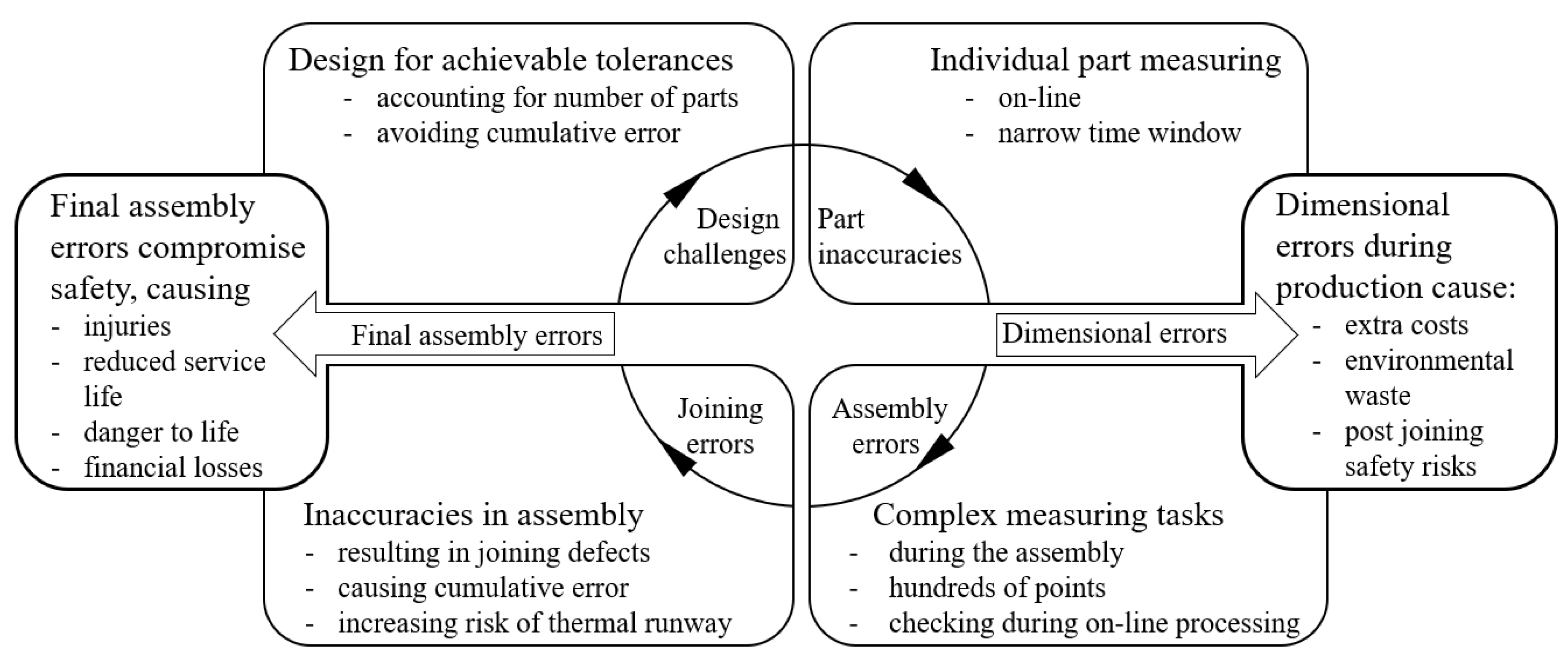
Challenges of battery parts production:
  • The parts, e.g., busbars, must be produced with high accuracy in accordance with tolerances set in sheet metal standard EN 485-4
  • The material used for the parts can affect measuring accuracy, e.g., a smooth and shiny surface may compromise optical measurements
-
Challenges of assembly:
  • The dimensional and positioning accuracy of the parts affects assembly. Typically, EV battery modules contain multiple dozens of cells. Therefore, the possible occurrence of cumulative error during assembly should be accounted for during the automatic assembly process
  • After assembling the components, the locations of the joints should be validated prior to the joining operation to avoid errors in joining. Assembly tools can generate errors in the assembly process due to tool wear or positioning errors. Therefore, quality measurement after assembly is required
-
Challenges of joining:
  • Precision of relative part location and orientation is essential for effective joining as positioning errors will result in unacceptable joints
Battery cell production is a complex production process and various assessment tools have been developed to manage quality. Numerous quality management tools and methods of battery cell production have the potential to be used in several steps of battery module production planning and control. Their use implies the intelligent adoption of quality gates for determining quality-relevant parameters and interactions. The intentions of the first iteration, process parameters, intermediate product properties and corresponding interactions are assessed using a modified failure mode and effect analysis (FMEA) and design of experiments (DoE) for quality-relevant parameter identification and classification. These results are then compiled in a matrix-based form, for example, as presented and stored in a database. Measurement and analysis of the data acquired enables the establishment of a gate-based quality management system in the production process [30].
Online process monitoring of battery joining process is effective method to avoid welding errors leading to joint failures [14]. In addition to the consideration of safety aspects of the individual cell components, pack-level safety features should also be met [31]. For example, when considering the safety of Li-ion packs, various modes of heat propagation from thermal runaway location to other cells need to be investigated. Single cells are known to reach 700 °C in the open air during thermal runaway. Joint failures can be critical sites for the start of thermal runaway and comprehensive measurement is crucial for the production of safe products [32]. The digital and optical 3D measuring tools described in this paper enable non-destructive measurement and several manufacturers produce equipment suitable for 100% inspection or inspection of randomly chosen samples.

4. Laser Welding of Battery Assembly Terminal Connections

Several methods can be used to connect the busbars to the terminals, including laser and ultrasonic welding, crimping or screw connections. Considering recent developments in real-time process monitoring, laser welding on-the-fly is becoming an exceptionally suitable joining method. For high volume serial manufacturing, laser welding is often chosen for its low heat input, fast operation, ease of automation and repeatability [33,34]. Characteristics of laser welding make the method suitable for battery pack applications: it is a non-contact process enabling high speed operations, execution of tailored weld patterns and welding any joint geometry, while being able to join dissimilar metals [15]. Three joint arrangements are used in the laser welding of busbars to battery cell terminal: lap joint, fillet joint and laser spot welding (see Figure 5).
Lap joint and laser spot welding methods are mainly used for welding terminal connections in prismatic, pouch and cylindrical cell types. Fillet joints are used when the terminal connection busbar design has a hole, and the edge of the opening should be fillet welded. Heat input of the battery terminal welding process must be low and depth of the penetration uniform to avoid damaging the battery cell [15]. As welding time is a major factor determining energy input, battery welding calls for lasers with very small focal point diameter and high energy density. With a small focal point diameter, advantages like small melt pool, low heat input and higher welding speeds are achieved. The main drawback of using a small focal point is the tight requirement for relative positioning accuracy of the busbar and battery terminal. Digital optical measuring is a potential method to ensure right fitting, as joint fit-up must be extremely precise to guarantee required strength and conductivity of the joint. Table 1 summarizes the advantages and disadvantages of different laser welding methods [13,15].

4.1. Lasers Used in Battery Welding

Lasers used for battery welding can be categorized according to the type of lasing media and wavelength. Generally, fiber, disk and fiber converted diode lasers are used in battery terminal welding. These lasers have good beam quality and focusabilty, wavelengths include the primary wavelengths of fiber and disk lasers. Laser systems delivering larger focal diameters have power levels up to 4 kW or higher, whereas systems enabling smaller beam diameter use single mode fiber lasers with power levels up to 3 kW. The characteristics of systems suitable for battery production are listed in Table 2.
During last decade, green and blue lasers became commercially available and are currently attracting interest because 450 nm and 532 nm wavelengths have better absorptivity in copper than near-infrared lasers [41]. Such lasers have mainly been used in scientific research, however, shorter wavelengths are especially beneficial for welding copper and currently have reached maturity for industrial use [42,43,44]. For instance, comparing performance of Trumpf’s green and infrared lasers in welding of copper at 1 kW power level under equal set-up, 515 nm wavelength produced approximately 50% deeper penetration, meaning that for a given penetration depth, processing speed can be increased [44].

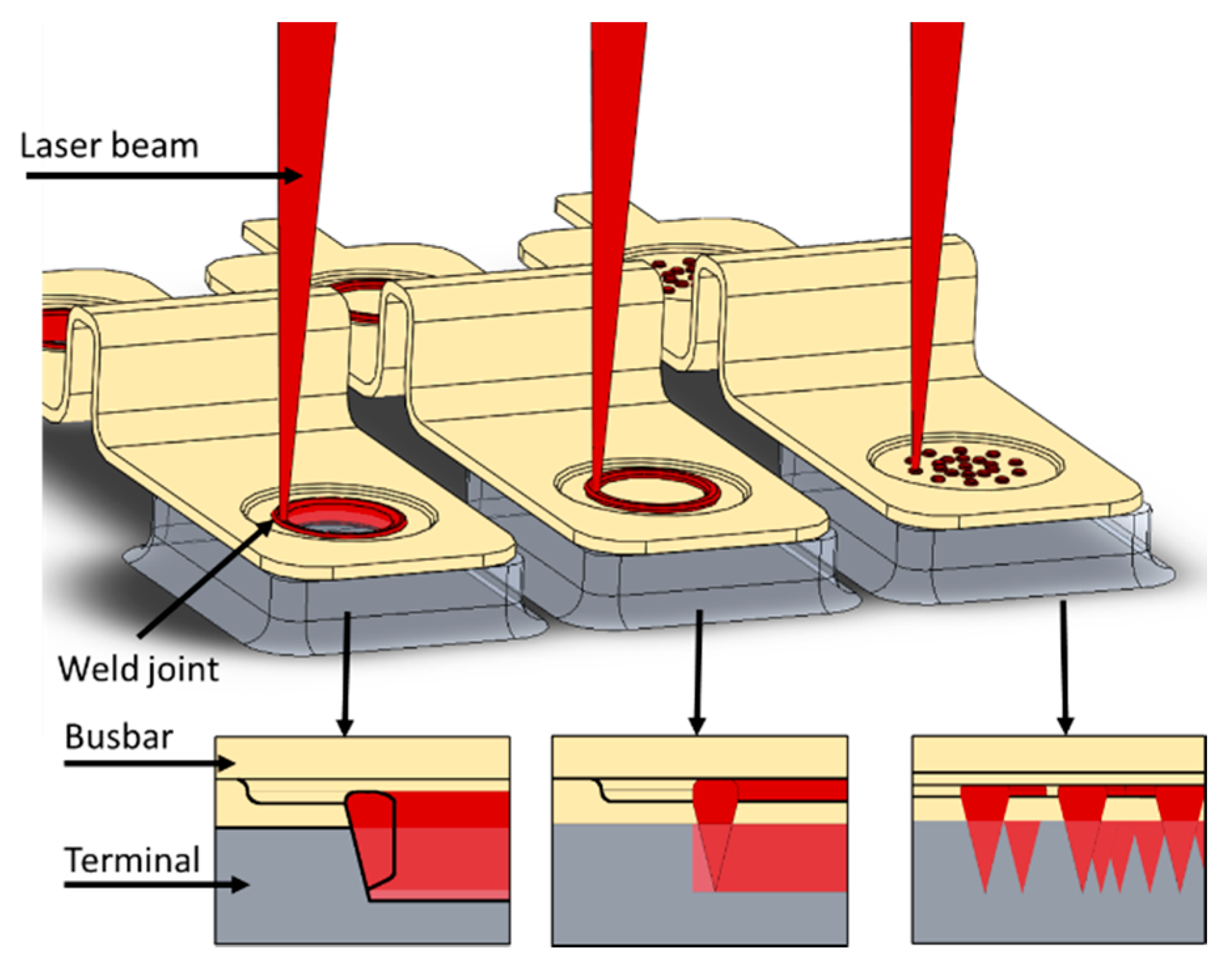
4.2. Welding Challenges of Different Busbar Designs and Joint Types

The diameter of laser beam focal point for battery terminal laser welding applications, also in industrial applications, ranges typically from 30 µm to 200 µm, as shown in Table 2. Small focal point diameters are required in precision welding applications. When laser welding fillet joints, the positional accuracy of the joint under the laser must be precise enough so that the focused beam focal point does not miss the joint. In the laser welding of busbars in lap joint configuration, a general guideline suggests the maximum gap between the joined materials to not exceed 5–10% of the thickness of the busbar [45]. Thus, the busbar must be positioned precisely with minimal gap to ensure the soundness of the laser welded joint (see Figure 6). The tolerance for misalignment is a function of the focused beam diameter (see Figure 6, detail B), consequently the distance between the busbar and battery cell terminal should be minimal.
As shown in Figure 6, detail A, 1.0 mm busbar material thickness permits maximum air gap of 0.1 mm. However, if the circular weld is 6.0 mm in diameter and the cell terminal has a misalignment of 0.95-degree angle, a 0.1 mm air gap is formed between the busbar and terminal [15]. In continuous weld seams, beam oscillation can be used to widen the melt pool and increase the melt volume to improve air gap bridging capability from 0.3 mm to 0.6 mm [46].

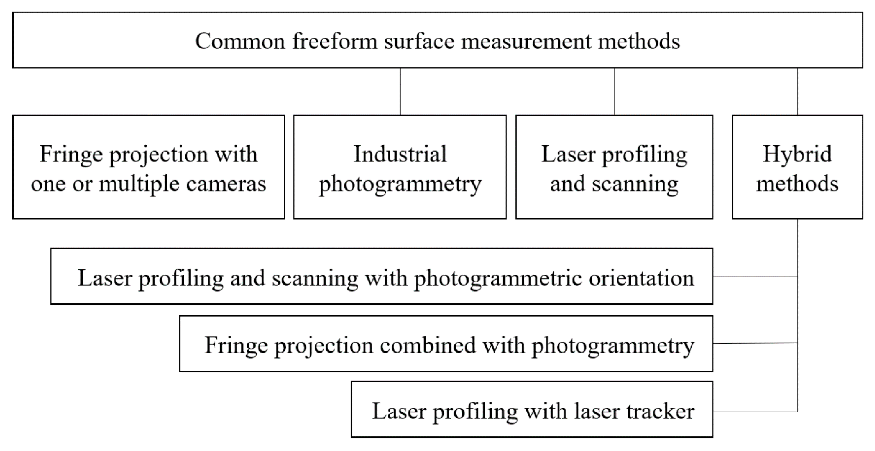
5. Optical Digital Measuring Technologies in Automated EV Battery Manufacturing

In this chapter, different non-contact optical measurement methods are introduced, categorized and evaluated. Figure 7 shows common contactless freeform surface measurement methods arranged into four main categories based on operation principle.

5.1. Fringe Projection with Single or Multiple Cameras

Fringe projection scanning is an active measurement method where a known pattern of light is projected onto the target surface and an image of the light pattern from surface is then captured by camera [47]. The pattern deforms and deflects based on the object topography, providing insights into the shape of the surface. The distance between the camera and projector must be known in this application. Fringe projection is considered as a structured light method and the term structured light is commonly used [48]. In fringe projection analysis, each pixel recorded by the camera is mapped to a 3D model. This is done mathematically by solving the light stripe to which the pixel belongs and then using trigonometric functions to solve the 3D coordinates of each point. Fringe projection scanning is a highly accurate measuring method, the error margin of 0.011 mm is reported in manufacturer’s calibration report while measuring with volume 560 × 420 × 420 mm [49]. According to [50], ambient light conditions do not have significant effects on accuracy of fringe projection scanning.

5.2. Industrial Photogrammetry

Industrial photogrammetry is a passive method where the image is processed without active illumination. The object is being photographed from different angles and triangulation is used to calculate the point cloud [51]. The system functions using multiple fixed cameras, repeatability of the measurements is reported to be ±0.02 mm with real production parts. The measurement speed is high; hundreds of 3D points can be gathered in less than 30 s [52]. Photogrammetry is mainly used in measuring large objects with the camera position not being fixed or pre-calibrated [53]. The camera positions are calculated after the image has been captured based on target positions. Achievable relative length measurement error is remaining between 1:50,000 and 1:100,000 [54]. This method has been mostly applied in component and body in white fabrication for in-line measuring and is therefore suitable also for battery module assembly.

5.3. Laser Profiling and Scanning

3D laser scanners use triangulation, time of flight, or phase shift for surface measurement [55]. In triangulation technique, the light from the measuring laser is aimed onto the surface and the Charge-Coupled Device (CCD) detector captures the beam image. If the distance between the laser and the object changes, the angle between the omitted laser light and the reflected laser light change accordingly, and CCD detector records the difference. The laser beam is registered in a different location by the CCD detector, triangulation is then used to calculate the height of the scanned point. Accuracy of triangulation laser scanning, when measuring a traceable sphere artefacts according to VDI/VDE 2634 part three, is between 0.025 mm–0.04 mm, depending on the scanner model [56].

5.4. Hybrid Solutions

Large objects often require certain details to be measured with high precision. For example, the height of the battery cells must be measured before welding with high accuracy, but the size of battery module itself in comparison is large. Because of this and the size of the scanning area of a typical 3D-scanner, the scanner must be repositioned during the process to cover whole surface. Consequently, relative motion occurs between the part and the 3D scanner, and the orientation of the measuring system (scanner) must thus be known in the global coordinate system so that local scans can be combined. The orientation of the measuring system (scanner) in the global coordinate system can be identified by different techniques, for example [57]:
  • Optical sensor navigation by external photogrammetric system
  • Mechanical sensor navigation by robot or articulated arm (the position information is received from the robot or from the articulated arm)
  • Photogrammetric orientation by means of control points
  • Point cloud matching by iterative closest point (ICP) or equivalent method.
A common combined method is applying fringe projection simultaneously with photogrammetry. The photogrammetry captures the reference points in order to align individual scans made by the fringe projection. An accuracy of 0.1 mm is possible when the object size remains within 15.4 m × 2.4 m × 2.3 m [58]. For instance, in automotive BIW (Body-in-White) inspection, certain areas are measured, however, the overlap between point clouds does not necessarily occur [59]. Optical sensor or mechanical sensor navigation are suitable solutions for such applications.
Another hybrid solution is combining laser scanning with external photogrammetric systems. The accuracy (EN-ISO 10360) of a laser profiling scanner equipped with an infrared camera system for tracking the scanner location (Zeiss T-SCAN 20) has been reported to be within 40 µm + 40 µm/1000 × L, where L is the measured length. For larger parts, the position of the laser scanner can be evaluated with a laser tracker. The accuracy (2-sigma) of the Leica AT960MR tracker with T-Scan is 60 µm if the measured length is under 8.5 m, and for length over 8.5 m, 26 µm + 4 µm/m [60]. Using hybrid techniques in battery module fabrication would unify the workflow, improve measuring accuracy over large area and thus be beneficial for increasing throughput speed.

5.5. Commercially Available Measurement Systems for Battery Welding

Battery module consists of around one hundred components and when considering the assembly of parts to be welded, numerous features must be measured. Optical scanning processes are significantly faster than touch probe methods. From the perspective of on-line measuring, the speed of point cloud analysis is a key factor. Point cloud analysis is dependent on the analysing software and remains out of the scope of this paper. The choice of the measuring system has been highly application dependent, however several of the systems reviewed in this study have the capacity to outperform currently used solutions, especially because of capability of non-contact 3D measuring. The characteristics of novel solutions that have recently entered the market and have the potential to be applied in battery module production are presented in Table 3.
The maximum permissible height error between terminals connected to busbar remains within 0.05 to 0.1 mm with devices shown in Table 3. All equipment listed in Table 3 can attain 0.1 mm accuracy and several operate with 0.05 mm accuracy. For laser welding of busbars in one battery module, which typically has a footprint smaller than 500 × 500 mm, thus all the equipment listed in Table 3 fulfills the precision requirements of battery welding operations.

6. Discussion

Many commercial battery modules use water cooling base plates (similar to liquid cooler in Figure 1). In the assembly process, to ensure sufficient contact between the cells using a top-down approach, cells within same plane need to be positioned with flatness tolerance of 0.1 mm. Optimal thermal conductivity from cells to cooling plates on the sides is formed when air gap between the cooling plate and the cells is zero. Realization of this is close to impossible when all production tolerances concerning cells are summarized, including assembly position errors and the flatness tolerance of cooling plates. For compensating, paste type material with good thermal conductivity is added between the sides of the cell and the cooling plates. However, limits of the thickness of the paste layer to maintain good thermal conductivity remains. Therefore, in the assembly phase preceding the welding, measuring the vertical plane flatness tolerance of the cell pack with the same scanner based device should be implied, so when cell pack flatness tolerance is exceeded, the welding process will not be executed and the low quality product can be discarded based on results of optical scanning method. The rejected battery module would be guided out of the production line and components involved would be recycled after investigation of the fault. Cells with faulty dimensions can further be replaced with proper ones. If the error is caused by assembly misalignment, creating new and more accurate assembly route for the same cell will solve the issue.
Height differences between adjacent terminals above 0.1 mm may cause a flaw in the laser welded joint, although equipment such as the Amada manufactured battery welding machine is able to compensate by pressing the busbar against the terminals to avoid the air gap. The pressing force bends the busbar against the terminal and thereby allows a wider tolerance than 0.1 mm, prior to the introduction of the pressing force. Similar configurations require measuring before and after the welding. When busbar thickness and its thickness tolerance is known, the 3D measurements of the top view of the battery module can be compared. In terminal positions, when the 3D point cloud is measured before welding, the material thickness of the busbar can be calculated into the height, thereby establishing a reference for the resulting value. In principle, errors can be detected in any direction. Furthermore, the proposed method has sufficient speed for being applied as an on-line process in battery module manufacturing.
Software used for data analysis creates differences as well, as each manufacturer offers their own tools for analyzing the 3D or point cloud data. However, universal software capable of accommodating with several different scanned data formats from different scanners are available and could be applied to analyze point clouds. PolyWorks from InnovMetrics is one of the most well-known solutions enabling the management of several input formats, however the application of software with similar functionalities is limited by the difficulties of task-specific optimization.

7. Conclusions

Assembly speed of a battery pack is influenced by the precision of the chosen measurement and welding methods. The throughput rate is also limited by the design of the busbars or other connector elements. Main conclusions drawn from this study are:
  • Quality of assembly in EV battery production is the cumulative impact of part tolerances, assembly features and welded joint quality.
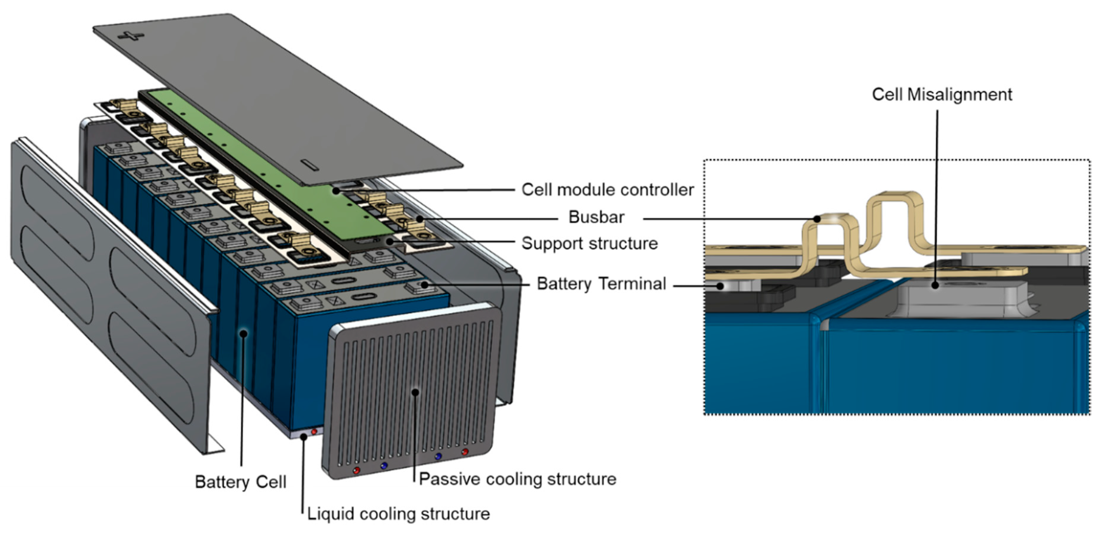
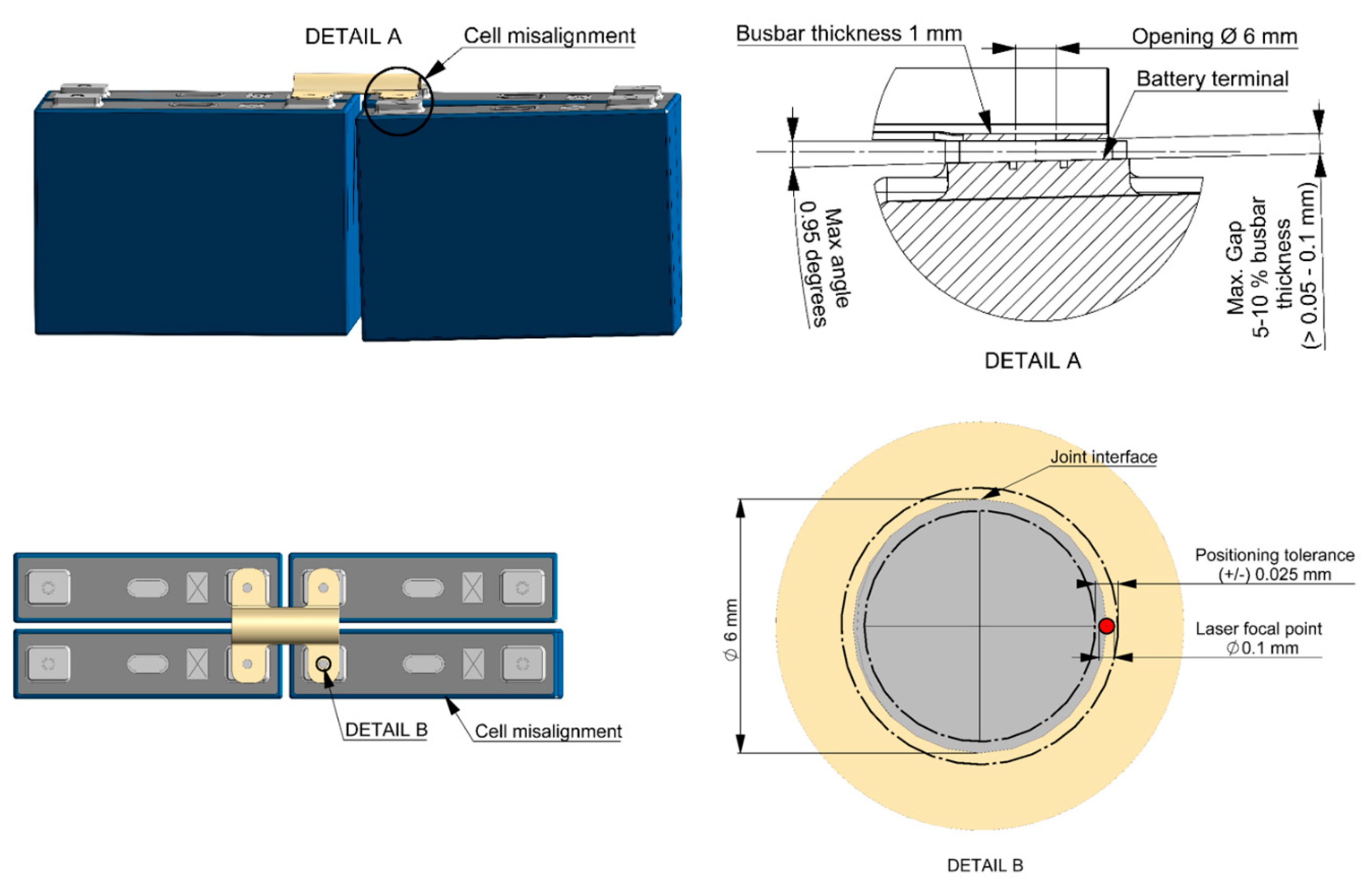
  • Typically, the busbar is pressed against the terminal to achieve a zero gap, as terminal height positioning accuracy has small tolerances. The amount of permitted deformation for acceptable welding quality is related to the geometry and material of the busbar.
  • The distance between the busbars and battery cell terminals should be minimized before laser welding. In battery module assembly, optical scanning measurement is a fast, non-contact method suitable for establishing the correct location of dozens of terminals prior to welding. Pouch-type cells are an exception because flexibility of the electrodes enables tight fitting.
  • Laser systems applied for welding the elements in battery terminal produce high energy density, producing beam diameters from 30 µm to 200 µm on material surface.
  • Digital optical measuring significantly shortens the time needed for acquiring the measurement values. High reliability and trackability of collected data help to ensure safety in future exploitation of the battery system.
  • The multi-purpose functionality of optical measuring devices makes them suitable for verifying the accuracy before and after welding operations, lessening the need for human visual inspection.
Quality assessment and metrology share a number of common attributes, implying that future advancements in accuracy and productivity are likely to result from process optimization through integration of machine vision and AI to current production processes.

Author Contributions

Methodology, H.S., A.S., and A.P.; formal analysis, H.S., A.P., A.U., J.H., T.R. and A.S.; investigation, H.S., A.P., A.U. and A.S.; data curation, H.S., A.P., A.U., J.H., T.R. and A.S.; writing—original draft preparation, H.S., A.P., J.H., A.U., T.R. and A.S.; writing—review and editing, H.S., A.U. and A.S.; visualization, A.P. and A.U.; supervision, A.S.; project administration, H.S. and A.S.; funding acquisition, H.S. and A.S. All authors have read and agreed to the published version of the manuscript.

Funding

The authors gratefully acknowledge the financial support of Business Finland’s for through project DigRob (grant numbers 2209/31/2017 and 9015/31/2017); this work is supported by Academy of Finland’s Strategic Research Council project MFG4.0 (# 313398). Institutions that have provided significant support for this work are LUT University, Turku University of Applied Sciences, and the City of Turku.

Acknowledgments

Authors would also like to express gratitude to all partners and companies of Me3DI project and MFG4.0 project for their contributions during this study.

Conflicts of Interest

The authors declare no conflict of interest.

References

  1. Nava, M. The Road Ahead for Electric Vehicles. 2017. Available online: https://www.bbvaresearch.com/wp-content/uploads/2017/02/170213_US_ElectricVehicles.pdf (accessed on 14 September 2020).
  2. Raff, R.; Golub, V.; Pelin, D.; Topic, D. Overview of Charging Modes and Connectors for the Electric Vehicles. In Proceedings of the 7th International Youth Conference on Energy (IYCE), Bled, Slovenia, 3–6 July 2020; pp. 1–6. [Google Scholar]
  3. Biresselioglu, M.E.; Demirbag Kaplan, M.; Yilmaz, B.K. Electric mobility in Europe: A comprehensive review of motivators and barriers in decision making processes. Transp. Res. Part A Policy Pract. 2018, 109, 1–13. [Google Scholar] [CrossRef]
  4. Hildermeier, J.; Kolokathis, C.; Rosenow, J.; Hogan, M.; Wiese, C.; Jahn, A. Smart EV Charging: A Global Review of Promising Practices. World Electr. Veh. J. 2019, 10, 80. [Google Scholar] [CrossRef] [Green Version]
  5. Gauthami, R.; Nair, V.V.; Sathish, A.; Vishnu Soureesh, K.; Ilango, K.; Sreelekshmi, R.S.; Ilangovan, S.A.; Sujatha, S. Design and Implementation of Efficient Energy Management System in Electric Vehicles. In Lecture Notes in Electrical Engineering; Springer: Berlin/Heidelberg, Germany, 2020; Volume 626, pp. 543–559. [Google Scholar]
  6. Iclodean, C.; Varga, B.; Burnete, N.; Cimerdean, D.; Jurchiş, B. Comparison of Different Battery Types for Electric Vehicles. IOP Conf. Ser. Mater. Sci. Eng. 2017, 252, 12058. [Google Scholar] [CrossRef] [Green Version]
  7. Pistoia, G.; Liaw, B. Behaviour of Lithium-Ion Batteries in Electric Vehicles, 1st ed.; Springer: Cham, Switzerland, 2018; ISBN 9783319699493. [Google Scholar]
  8. Zeng, X.; Li, M.; Abd El-Hady, D.; Alshitari, W.; Al-Bogami, A.S.; Lu, J.; Amine, K. Commercialization of Lithium Battery Technologies for Electric Vehicles. Adv. Energy Mater. 2019, 9, 1900161. [Google Scholar] [CrossRef]
  9. Zubi, G.; Dufo-López, R.; Carvalho, M.; Pasaoglu, G. The lithium-ion battery: State of the art and future perspectives. Renew. Sustain. Energy Rev. 2018, 89, 292–308. [Google Scholar] [CrossRef]
  10. Li, J.; Zhou, S.; Han, Y. (Eds.) Advances in Battery Manufacturing, Service, and Management Systems; John Wiley & Sons, Inc.: Hoboken, NJ, USA, 2016; ISBN 9781119060741. [Google Scholar]
  11. Mikkelstrup, A.; Thomsen, M.; Stampe, K.; Endelt, B.; Boll, J.; Kristiansen, E.; Kristiansen, M. Quality Inspection System for Robotic Laser Welding of Double-Curved Geometries. Procedia Manuf. 2019, 36, 50–57. [Google Scholar] [CrossRef]
  12. Arora, S.; Shen, W.; Kapoor, A. Review of mechanical design and strategic placement technique of a robust battery pack for electric vehicles. Renew. Sustain. Energy Rev. 2016, 60, 1319–1331. [Google Scholar] [CrossRef]
  13. Zwicker, M.F.R.; Moghadam, M.; Zhang, W.; Nielsen, C.V. Automotive battery pack manufacturing – a review of battery to tab joining. J. Adv. Join. Process. 2020. [Google Scholar] [CrossRef]
  14. Das, A.; Li, D.; Williams, D.; Greenwood, D. Joining Technologies for Automotive Battery Systems Manufacturing. World Electr. Veh. J. 2018, 9, 22. [Google Scholar] [CrossRef] [Green Version]
  15. Shannon, G. Improve Tab to Terminal Connections in Battery Pack Manufacturing. Available online: https://www.batterypoweronline.com/articles/improve-tab-to-terminal-connections-in-battery-pack-manufacturing/ (accessed on 14 September 2020).
  16. Stavridis, J.; Papacharalampopoulos, A.; Stavropoulos, P. Quality assessment in laser welding: A critical review. Int. J. Adv. Manuf. Technol. 2018, 94, 1825–1847. [Google Scholar] [CrossRef]
  17. Allwood, J.M.; Childs, T.H.C.; Clare, A.T.; De Silva, A.K.M.; Dhokia, V.; Hutchings, I.M.; Leach, R.K.; Leal-Ayala, D.R.; Lowth, S.; Majewski, C.E.; et al. Manufacturing at double the speed. J. Mater. Process. Technol. 2015, 229, 729–757. [Google Scholar] [CrossRef] [Green Version]
  18. Schnell, J.; Reinhart, G. Quality Management for Battery Production: A Quality Gate Concept. Procedia CIRP 2016, 57, 568–573. [Google Scholar] [CrossRef]
  19. Kölmel, A.; Sauer, A.; Lanza, G. Quality-oriented Production Planning of Battery Assembly Systems for Electric Mobility. Procedia CIRP 2014, 23, 149–154. [Google Scholar] [CrossRef] [Green Version]
  20. Glorieux, E.; Franciosa, P.; Ceglarek, D. Coverage path planning with targetted viewpoint sampling for robotic free-from surface inspection. Robot. Comput. Integr. Manuf. 2020, 61, 101843. [Google Scholar] [CrossRef]
  21. Savio, E.; De Chiffre, L.; Carmignato, S.; Meinertz, J. Economic benefits of metrology in manufacturing. CIRP Ann. Manuf. Technol. 2016, 65, 495–498. [Google Scholar] [CrossRef]
  22. Pettinger, K.H.; Kampker, A.; Hohenthanner, C.R.; Deutskens, C.; Heimes, H.; vom Hemdt, A. Lithium-ion cell and battery production processes. In Lithium-Ion Batteries: Basics and Applications; Springer: Berlin, Germany, 2018; pp. 211–226. ISBN 9783662530719. [Google Scholar]
  23. Kraetzsch, M.; Standfuss, J.; Klotzbach, A.; Kaspar, J.; Brenner, B.; Beyer, E. Laser Beam Welding with High-Frequency Beam Oscillation: Welding of Dissimilar Materials with Brilliant Fiber Lasers. Phys. Procedia 2011, 12, 142–149. [Google Scholar] [CrossRef]
  24. Schröder, R.; Aydemir, M.; Seliger, G. Comparatively Assessing different Shapes of Lithium-ion Battery Cells. Procedia Manuf. 2017, 8, 104–111. [Google Scholar] [CrossRef]
  25. Feng, X.; Ouyang, M.; Liu, X.; Lu, L.; Xia, Y.; He, X. Thermal runaway mechanism of lithium ion battery for electric vehicles: A review. Energy Storage Mater. 2018, 10, 246–267. [Google Scholar] [CrossRef]
  26. Zhang, S. Recent progresses on real-time 3D shape measurement using digital fringe projection techniques. Opt. Lasers Eng. 2010, 48, 149–158. [Google Scholar] [CrossRef]
  27. Niu, H.; Chen, C.; Ji, D.; Li, L.; Li, Z.; Liu, Y.; Huang, X. Thermal-Runaway Propagation over a Linear Cylindrical Battery Module. Fire Technol. 2020. [Google Scholar] [CrossRef]
  28. Baumann, M.; Wildfeuer, L.; Rohr, S.; Lienkamp, M. Parameter variations within Li-Ion battery packs—Theoretical investigations and experimental quantification. J. Energy Storage 2018, 18, 295–307. [Google Scholar] [CrossRef]
  29. Kenney, B.; Darcovich, K.; MacNeil, D.D.; Davidson, I.J. Modelling the impact of variations in electrode manufacturing on lithium-ion battery modules. J. Power Sources 2012, 213, 391–401. [Google Scholar] [CrossRef]
  30. Plötz, P.; Schneider, U.; Globisch, J.; Dütschke, E. Who will buy electric vehicles? Identifying early adopters in Germany. Transp. Res. Part A Policy Pract. 2014, 67, 96–109. [Google Scholar] [CrossRef]
  31. Hollatz, S.; Kremer, S.; Ünlübayir, C.; Sauer, D.U.; Olowinsky, A.; Gillner, A. Electrical Modelling and Investigation of Laser Beam Welded Joints for Lithium-Ion Batteries. Batteries 2020, 6, 24. [Google Scholar] [CrossRef] [Green Version]
  32. Wilke, S.; Schweitzer, B.; Khateeb, S.; Al-Hallaj, S. Preventing thermal runaway propagation in lithium ion battery packs using a phase change composite material: An experimental study. J. Power Sources 2017, 340, 51–59. [Google Scholar] [CrossRef]
  33. Kirchhoff, M. Laser Applications in Battery Production—From Cutting Foils to Welding the Case. 2013, pp. 1–3. Available online: https://0-ieeexplore-ieee-org.brum.beds.ac.uk/abstract/document/6689743/ (accessed on 14 September 2020).
  34. Lee, S.S.; Kim, T.H.; Hu, S.J.; Cai, W.W.; Abell, J.A. Joining technologies for automotive lithium-ion battery manufacturing—A review. In Proceedings of the ASME 2010 International Manufacturing Science and Engineering Conference, MSEC 2010, Erie, PA, USA, 12–15 October 2010; Volume 1, pp. 541–549. [Google Scholar]
  35. Schmitz, P. Comparative Study on Pulsed Laser Welding Strategies for Contacting Lithium-Ion Batteries. Adv. Mater. Res. 2016, 1140, 312–319. [Google Scholar] [CrossRef]
  36. Brand, M.J.; Schmidt, P.A.; Zaeh, M.F.; Jossen, A. Welding techniques for battery cells and resulting electrical contact resistances. J. Energy Storage 2015, 1, 7–14. [Google Scholar] [CrossRef]
  37. Dimatteo, V.; Ascari, A.; Fortunato, A. Continuous laser welding with spatial beam oscillation of dissimilar thin sheet materials (Al-Cu and Cu-Al): Process optimization and characterization. J. Manuf. Process. 2019, 44, 158–165. [Google Scholar] [CrossRef]
  38. Schmidt, P.A.; Schweier, M.; Zaeh, M.F. Joining of lithium-ion batteries using laser beam welding: Electrical losses of welded aluminum and copper joints. In Proceedings of the ICALEO 2012—31st International Congress on Applications of Lasers and Electro-Optics, Anaheim, CA, USA, 23–27 September 2012; Volume 2012, pp. 915–923. [Google Scholar]
  39. Fetzer, F.; Jarwitz, M.; Stritt, P.; Weber, R.; Graf, T. Fine-tuned Remote Laser Welding of Aluminum to Copper with Local Beam Oscillation. Phys. Procedia 2016, 83, 455–462. [Google Scholar] [CrossRef] [Green Version]
  40. Solchenbach, T.; Plapper, P.; Cai, W. Electrical performance of laser braze-welded aluminum–copper interconnects. J. Manuf. Process. 2014, 16, 183–189. [Google Scholar] [CrossRef]
  41. Zediker, M.S.; Fritz, R.D.; Finuf, M.J.; Pelaprat, M.J. Laser Welding Components for Electric Vehicles with a High-Power Blue Laser System. In Proceedings of the ICALEO 2019, Orlando, FL, USA, 7–10 October 2019; LIA: Orlando, FL, USA, 2019; p. 104. [Google Scholar]
  42. Helm, J.; Schulz, A.; Olowinsky, A.; Dohrn, A.; Poprawe, R. Laser welding of laser-structured copper connectors for battery applications and power electronics. Weld. World 2020, 64, 611–622. [Google Scholar] [CrossRef] [Green Version]
  43. Giordano, G. Laser welding advances fuel new applications. Manuf. Eng. 2018, 160, LF5–LF11. [Google Scholar]
  44. Kaiser, E.; Dold, E.M.; Killi, A.; Zaske, S.; Pricking, S. Application benefits of welding copper with a 1 kW, 515 nm continuous wave laser. Batter. Congr. 2019, 2019, 1–6. [Google Scholar]
  45. Havrilla, D.; Ryba, T.; Holzer, M. High-Power Disk Lasers: Advances and Applications. Available online: https://lia.scitation.org/doi/abs/10.2351/1.5062465 (accessed on 14 September 2020).
  46. Müller, A.; Goecke, S.F.; Rethmeier, M. Laser beam oscillation welding for automotive applications. Weld. World 2018, 62, 1039–1047. [Google Scholar] [CrossRef]
  47. Rodrigues, M.; Kormann, M.; Schuhler, C.; Tomek, P. An Intelligent Real Time 3D Vision System for Robotic Welding Tasks. In Proceedings of the 2013 9th International Symposium on Mechatronics and its Applications (ISMA), Amman, Jordan, 9–11 April 2013; pp. 1–6. [Google Scholar]
  48. Wang, Z.; Nguyen, D.A.; Barnes, J. Recent advances in 3D shape measurement and imaging using fringe projection technique. In Proceedings of the Society for Experimental Mechanics—SEM Annual Conference and Exposition on Experimental and Applied Mechanics 2009, Albuquerque, NM, USA, 1–4 June 2009; Volume 4, pp. 2644–2653. [Google Scholar]
  49. GOM. GOM Acceptance Test, Certificate No. 110826_CP20-170-60086. Acceptance/Reverification Base on VDI/VDE 2634, Part 3. 2011. Available online: https://www.zebicon.com/fileadmin/user_upload/2_Maaleudstyr/9_Certifikater/ATOS_Core_200_SN160300/2019-04-02_Acceptance_test_ATOS_Core_MV200_SN160300.pdf (accessed on 14 September 2020).
  50. Li, F.; Stoddart, D.; Zwierzak, I. A Performance Test for a Fringe Projection Scanner in Various Ambient Light Conditions. Procedia CIRP 2017, 62, 400–404. [Google Scholar] [CrossRef]
  51. Robson, S.; MacDonald, L.; Kyle, S.; Boehm, J.; Shortis, M. Optimised multi-camera systems for dimensional control in factory environments. Proc. Inst. Mech. Eng. Part B J. Eng. Manuf. 2018, 232, 1707–1718. [Google Scholar] [CrossRef]
  52. Tuominen, V. The measurement-aided welding cell—Giving sight to the blind. Int. J. Adv. Manuf. Technol. 2016, 86, 371–386. [Google Scholar] [CrossRef] [Green Version]
  53. Cuypers, W.; Van Gestel, N.; Voet, A.; Kruth, J.-P.; Mingneau, J.; Bleys, P. Optical measurement techniques for mobile and large-scale dimensional metrology. Opt. Lasers Eng. 2009, 47, 292–300. [Google Scholar] [CrossRef] [Green Version]
  54. Luhmann, T.; Robson, S.; Kyle, S.; Boehm, J. Close-Range Photogrammetry and 3D Imaging, 2nd ed.; De Gruyter: Berlin, Germany, 2013. [Google Scholar]
  55. Stavroulakis, P.I.; Leach, R.K. Review of post-process optical form metrology for industrial-grade metal additive manufactured parts. Rev. Sci. Instrum. 2016, 87, 041101. Available online: https://aip.scitation.org/doi/abs/10.1063/1.4944983 (accessed on 14 September 2020). [CrossRef]
  56. Creaform Creaform. Available online: https://www.creaform3d.com/ (accessed on 14 September 2020).
  57. Luhmann, T. Close range photogrammetry for industrial applications. ISPRS J. Photogramm. Remote Sens. 2010, 65, 558–569. [Google Scholar] [CrossRef]
  58. GOM. Available online: www.gom.com (accessed on 10 November 2019).
  59. Rao, M.R.; Radhakrishna, D.; Usha, S. Development of a Robot-mounted 3D Scanner and Multi-view Registration Techniques for Industrial Applications. Procedia Comput. Sci. 2018, 133, 256–267. [Google Scholar] [CrossRef]
  60. Hexagon Leica Absolute Tracker AT960. Available online: https://www.hexagonmi.com/products/laser-tracker-systems/leica-absolute-tracker-at960 (accessed on 20 October 2019).
Figure 1. (left) Schematic representation of automotive battery module in assembly; (right) Detailed view of busbar-electrode interface to be measured on-line prior to welding.
Batteries 06 00047 g001
Figure 2. Design considerations in electric vehicle (EV) battery pack manufacturing.
Batteries 06 00047 g002
Figure 3. Commercially available cell and module types with electrical contact joining methods.
Batteries 06 00047 g003
Figure 4. Production speed-accuracy trade off in battery cell manufacturing.
Batteries 06 00047 g004
Figure 5. Standard methods of laser joining battery connections: fillet joint (left), lap joint (middle), multiple spot welds (right).
Batteries 06 00047 g005
Figure 6. Positioning accuracy tolerances in battery tap welding with 0.1 mm diameter of laser focal point and 1.0 mm busbar thickness.
Batteries 06 00047 g006
Figure 7. Common freeform surface measurement methods.
Batteries 06 00047 g007
Table 1. Comparison of different battery assembly methods by laser welding. Schematic images represent commercially available industrial solutions.
Joining MethodSchematic Representation
Laser wire bonding Batteries 06 00047 i001
+
No need for a stamped busbar
+
No positioning of rigid connectors is required
+
Flexible design
+
Easy compensation of tolerances
+
Special welding and clamping device required
Fillet welding of busbar Batteries 06 00047 i002
+
Rigidity
+
Joints can be checked visually
-
Terminal height or angle variance can cause a gap between the terminal and busbar
-
Laser weld positioning accuracy needs to be very high
Laser spot welded busbar Batteries 06 00047 i003
+
Rigidity
+
Weld position does not need to be very accurate
-
Welds cannot be checked after welding
-
Terminal height variance may cause a gap between the terminal and busbar
Laser lap joint welded busbar Batteries 06 00047 i004
+
Rigidity
+
The weld position requirement is not very stringent
-
Welds cannot be checked after welding
-
Variance of terminal height or angle may cause a gap between the terminal and busbar
Laser lap joint welded pouch cells Batteries 06 00047 i005
+
Weld position does not need to be very accurate
-
Demanding fixturing
Table 2. Summary of laser types and material combinations in battery terminal welding.
Beam SourcePower (W)MaterialFocused Beam Diameter (µm)Wavelength (nm)Reference
Disk laser MM/CW4000Steel/Steel1701030[35]
Fiber laser SM/CW3000Brass/Brass501070[36]
Fiber laser SM/CW1000Al/Cu/Al601070[37]
Fiber laser SM/CW3000Al/Cu501070[38]
Fiber laser SM/CW2000Al/Cu351070[23]
Diode laser MM/CW4000Al/Cu2801080 1[39]
Fiber Laser SM/CW400Al/Cu311070[40]
1 Beam converted diode laser.
Table 3. Optical measuring systems: characteristics and operating principles.
SystemPrincipleMeasuring Volume or AreaVolumetric AccuracyScanning Area
Zeiss T-Scan 20Laser scanning with external photogrammetric orientation20 m30.04 mm + 0.04 (L/1000) mm125 mm line
Creaform Metrascan 750 EliteLaser scanning with external photogrammetric orientation16.6 m30.078 mm275 × 250 mm
Creaform HandyScan BLACKLaser scanningRecommended part size 0.05–4 m;0.02 mm + 0.06 mm/m310 × 350 mm
Leica AT960MR and T-ScanLaser scanning with laser tracker20 m0.06 mm/0.026 mm + 0.004 mm/m100 mm line at standoff distance
Hexagon absolute armLaser scanning with mechanical armMax reach 3480 mm0.066 mm (LDIA value is the maximum permissible error for the articulation location, according to ISO 10360-8 Annex D)115 mm line
GOM Atos III Triple ScanFringe projection38 × 29 × 15–2000 × 1500 × 1500 mm30.011 mm (sphere spacing error, measuring volume 560 × 420 × 420 mm)Not specified
Creaform Maxshot Next ElitePhotogrammetry2–10 m0.015 mm/m (Based on VDI/VDE 2634 part 1)Not specified
Mapvision Quality Gate 2200 SeriesPhotogrammetry, Multi-camera330 × 860 × 320 mmRepeatability: +/−0.02 mmNot specified
Mapvision Quality Gate 6200 SeriesPhotogrammetry, Multi-cameraAny standard car or body in white: 5 × 2.3 × 1.5 mRepeatability: +/−0.02 mmNot specified

