
Early Detection of Failing Automotive Batteries Using Gas Sensors


1
Virtual Vehicle Research GmbH, Inffeldgasse 21a, 8010 Graz, Austria
2
Sensirion AG, Laubisruetistrasse 50, 8712 Staefa, Switzerland
*
Author to whom correspondence should be addressed.
Batteries 2021, 7(2), 25; https://0-doi-org.brum.beds.ac.uk/10.3390/batteries7020025
Submission received: 5 February 2021
/
Revised: 10 March 2021
/
Accepted: 26 March 2021
/
Published: 12 April 2021
(This article belongs to the Special Issue Batteries and Electric Vehicles)
Abstract
:Safety for automotive lithium-ion battery (LIB) applications is of crucial importance, especially for electric vehicle applications using batteries with high capacity and high energy density. In case of a defect inside or outside the cell, serious safety risks are possible including extensive heat generation, toxic and flammable gas generation, and consequently fire and explosion. New regulations (GB 38031-2020) require a warning for passengers at least five minutes before serious incidents. This regulation can hardly be fulfilled with state-of-the-art battery monitoring. In this study, gases produced during battery failure before and during a thermal runaway (TR) are investigated in detail and the use of different gas sensors as early detectors of battery incidents is tested and proposed. The response of several commercially available gas sensors is tested in four battery failure cases: unwanted electrolysis of voltage carrying parts, electrolyte vapor, first venting of the cell and the TR. The experiments show that battery failure detection with gas sensors is possible but depends highly on the failure case. The chosen gas sensor can detect H2 produced by unwanted electrolysis and electrolyte vapor and gases produced by degassing of state-of-the-art LIBs. The results may contribute significantly to failure detection and improvement of battery safety.
1. Introduction
Reliable battery packs are a key component for electric vehicles (EVs). Global competition forces battery producers to increase energy density, to reduce the costs of their products and to maintain an acceptable safety level at the same time. Safety for lithium-ion battery (LIB) applications is challenged by possible defects inside or outside the cell causing exothermic reactions, such as the thermal runaway (TR). During the TR, extensive amounts of heat, toxic and flammable gas and hot particles are generated with critical consequences like fire, explosion and toxic atmosphere [1,2,3,4]. Thus, TR prevention and early failure detection before serious battery failure incidents need to be addressed.
Developing methods for early failure detection and reducing safety risks from failing high energy LIBs has become a major challenge for industry, research and development [5]. State-of-the-art battery monitoring equipment applied in the EV battery pack, like cell voltage measurement and temperature sensors, are insufficient to reach an acceptable level of safety and to reliably enable early failure detection. New regulations such as GB 38031-2020 and discussions such as Electrical Vehicle Safety—Global Technical Regulation (EVS-GTR) prescribe a warning for passengers at least five minutes before serious incidents [6,7].
In order to enhance battery safety and to fulfill EVS-GTR20 and GB 38031-2020, the use of additional gas sensors combined with state-of-the-art battery failure monitoring such as voltage, temperature, and pressure measurement, is promising and needs to be investigated in more detail.
1.1. Early Failure Detection in Battery Packs
The battery management system (BMS) is the heart of battery operation, performance, monitoring and failure detection inside EVs. The BMS is designed to ensure safe and reliable operation of batteries and should meet functional safety standards ISO 26262. This control unit manages cell balancing, thermal management, charge and discharge control, cell monitoring, state estimation such as state-of-charge (SOC) and state-of-health (SOH) [8]. A good BMS is designed particularly for the specific cells and modules according to their safety limits. Current functional-safety cell monitoring means monitoring the electric and thermal behavior of the cell in real-time: the cell voltage and current can be measured directly by means of on-board current and voltage sensors and the surface temperature of battery pack components directly with temperature sensors [9]. While some manufacturers use temperature sensors on each cell surface, others reduce them inside the battery pack to an absolute minimum [10]. Additional monitoring systems are insulation detection and the high-current fuse. To the authors’ current knowledge, no additional early failure detection methods are used in series products.
As soon as an abnormal behavior of the cell voltage, the current or the cell temperature of one or more batteries is detected, predefined actions are executed by the BMS (e.g., control unit activates cooling or interrupts the power circuit). In case of a detected failure, different shutdown procedures are followed [6,11].
However, the standard state-of-the-art battery monitoring equipment in current EV battery packs is inadequate to reach the upcoming level of safety requirements and to reliably enable early failure detection, because battery failure cases such as electrolysis, an open cell housing and electrolyte vaporization or the first venting are very unlikely to be detected by the classical monitoring system. The first venting is when the cell housing (hard case or pouch bag) opens before the TR, since gas is produced inside the cell due to evaporation or decomposition processes [3]. For cells without a current interrupt device (CID) or overcharge safety device (OSD), this first venting precedes the cell voltage breakdown and is detectable through a small temperature increase directly at the venting position of the failing cell [3]. It is not possible to measure this venting with thermocouples applied on the cell surface, with cell voltage monitoring or with current monitoring. It is very likely that with these thermocouples, the voltage or current measurement only detect the failing behavior if at least one of the cells is already in the state of a TR. But this opening of the housing leads to emersion of electrolyte (liquid and gaseous), which is known to be flammable, irritant, toxic, and/or corrosive depending on the exact composition of the electrolyte mixture [12,13,14] and would be a valuable warning for an emerging failure such as a TR event.
In this study we show that an additional gas sensor added to the existing monitoring system inside the battery pack can detect battery failures quickly and cost efficiently before serious incidents. A detailed characterization of hazards such as gas emission and vent gas composition before TR is valuable for the community and for finding suitable sensors for early failure detection.
1.2. Literature on Battery Failure Detection with Gas Sensors
The basic idea of using gas sensors for detecting battery vent gases produced during battery failures, additional to the existing BMS monitoring sensors, is not new. Researchers have published suggestions for using gas sensors for detecting battery failures [5,11,15,16,17,18] and have reported field experiments on gas sensors in battery TRs [10,11,19]. Patent applications have also been published proposing the implementation of gas sensors for TR detection [5,20]. The following literature review is divided into two groups: literature focusing on gases produced during the TR and literature focusing on gases produced before the TR reaction.
For detecting the TR itself and gases developed during the TR reaction, gases such as CO, CO2, H2, CH4, C2H4, C2H6, C3H8 are addressed [2], and sensors to detect at least one of these gases are chosen.
Cai et al. used early failure detection by means of detection of CO2 gas produced at the TR of the first 18650 NMC cell [15]. They stated that the measurement of CO2 allows a significantly faster TR detection than conventional surface temperature sensing. Koch et al. tested a sensor set consisting of voltage sensor, temperature sensor, pressure sensor, gas sensor, smoke sensor, and creep distance sensor in TR experiments of NMC pouch cells [11]. They found that the gas sensor can detect the TR event earlier than the other sensors during nail-penetration tests. Koch et al. used a SnO2 gas sensor (metal oxide semiconductor (MOx, also named MOS)) sensitive to CH4, C3H8 and CO. Each tested sensor detected the TR independently of battery size and energy density. The authors stated that the combination of several sensors might lead to an improvement of the system. Mateev et al. proposed gas detection with a MQ-7 (TR gases CO and H2 are the target gases) MOx gas sensor showing results of failing 18650 LIBs [16]. One sensitive MOx layer was applied to the relatively large analogue sensor. Liao et al. published a survey of methods for monitoring and detection of TR of LIBs [5]. They stated that the combination of voltage, cell surface temperature, inner cell temperature and gas monitoring in battery applications is the most efficient method to promote safety of LIBs. Concerning vent gas detection, they described target gases produced during the TR, such as CO, CO2, C2H4, C2H6, H2O, C3H6 and O2, but they stated that gas sensors can detect battery failure related signals seven to eight minutes before the TR, which would mean earlier detection of the gas signal compared to the voltage drop or a temperature signal.
Other researchers have focused on volatile organic compounds (VOCs) such as electrolyte components, which can be measured at battery failure stages before the TR:
Cummings et al. proposed in the US patent application monitoring of electrolyte vapor such as diethyl carbonate (DEC) and dimethyl carbonate (DMC) [20]. Hill et al. introduced the principle of off gas sensing prior to TR in overcharge experiments using cylindrical, pouch and prismatic cells [19]. They tested a chemi-resistive sensor, sensitive to CO, CH4, C2H6, VOCs, C2H4, C3H8, HF, but did not disclose details on the sensing material or operating conditions. The lifetime of the tested sensor is lower than five years. They observed in overcharge tests that the sensor reacted to battery off-gassing 10 min before the TR itself. Swartz et al. promoted the same chemi-resistive sensor element for H2 measurements and announced refined formulations for detecting CO, CHx and VOCs [21]. Wenger et al. presented insight into the gas sensor response of MOx sensors during electrolyte leakage and battery overcharge experiments of pouch cells [10]. They stated that a first venting eventually occurs and that the time between the first venting and the TR depends on the applied current in the overcharge test. The manufacturer of the sensor is not disclosed in their paper. Herold et al. promoted sensors fabricated by AMS for detecting critical battery states (overcharge, nail penetration) [18]. They tested their MOx gas sensor in abuse tests such as nail-penetration, overcharging, short circuit and leakage on pouch cells, as well as during charging and temperature cycles, and demonstrated the reaction of the MOx sensor to electrolyte vapor. They suggested a focus on the resistance change relative to the background rather than to the absolute resistance value.
1.3. What Is Missing in the Current Literature and What Is Needed
A detailed analysis of gases produced during battery failure cases before TR is poorly reported in current literature. Most literature is based on gases produced at the TR itself [2,14,22,23,24,25]. In this scientific field it is relevant to gain insight into the gas production even before the TR in order to identify suitable gas sensors. The possible battery failure case of unwanted electrolysis between two voltage carrying parts and resulting H2 production is rarely addressed in the literature but is a possible and serious battery failure case because of the high flammability of H2. While detecting the TR allows the setting up of actions to prevent TR propagation to the neighboring cells, focusing on the failure stages before the TR is indispensable to prevent the TR itself. Thus, a detailed analysis of evolving gases at battery failure stages before the TR would be valuable.
Even though TR monitoring with gas sensors has been claimed to be more efficient than voltage and temperature monitoring for failure detection [5], validation and comparison of several possible gas sensors for early detection of battery failures is currently insufficiently addressed in the literature but would be valuable for research and industry concerned with battery safety.
Because the first venting does not occur in all failure cases [3] and the exact time when the cell housing opens and releases gases depends on more factors than just the overcharge current, it is relevant to investigate which battery failure cases can be detected and if it is possible to detect battery failures with gas sensors at an early stage.
Furthermore, an algorithm for event detection is needed and the measurement with the gas sensor approach needs to be stable against false positives. Considerations to enable distinguishing between battery failure cases and preventing false positives is necessary, but is not mentioned in the reviewed literature and currently unsolved.
In this study we investigate battery failure cases BEFORE the TR in detail, including electrolysis, and we identify and quantify the gas components and several selected commercially available sensors which detect compounds emitted during the gas producing events before the TR. Different sensor principles and sensors from different manufacturers were benchmarked in special test setups. The most promising gas sensors were tested inside a TR test bed using more than 30 different state-of-the-art automotive LIBs in three different TR triggers: overtemperature, overcharge and nail-penetration. Thus, the influence of the failure case on battery failing behavior is explored and algorithms for event detection are suggested. Additionally, sensors were targeted, which enables distinction between different failure cases, and which allows algorithms to prevent false positives produced by surrounding gases.
2. Methods and Measurement Technology
The idea of this study is to enhance battery safety and improve the concept of early detection of battery failures using gas sensors and pressure monitoring inside the battery pack, additional to state-of-the-art battery failure monitoring. The diagram in Figure 1 shows the improved concept for early detection of battery failures. The new concept adds the monitoring of the pressure inside the battery pack (cell pressure to neighboring cells and ambient pressure), as well as the detection of battery failures associated with gas emissions by means of gas sensor technologies. In this study, the focus is put on the additional benefit of using gas sensors for early failure detection. To do so, the use of gas sensors was tested in possible battery failure cases.
Upon exceeding defined operation thresholds, a warning is sent out and a reduction of power supply is requested, or the BMS disconnects the system from the mains. The other components (cells, cooling system, cabling) and functions (tightness of the battery housing, tightness of the cooling system) are secured by quality management in production. Monitoring of these components and functions with gas sensors (VOC, H2, CO2, CO) and environmental sensors (pressure, air humidity) is planned as a supplement in this enhanced concept for early detection of battery failures. The concrete action of the BMS, the quality management in production and the implementation of the gas sensors into the application are not part of this study. Suggestions for the implementation of the sensors inside the battery pack are listed in [10].
2.1. Early Failure Detection Method Development
2.1.1. Battery Failure Cases
Under normal operating conditions of the battery, no gas emission is expected. In order to find suitable early failure detection methods, four concrete battery failure cases known to involve gas emissions were investigated experimentally: (a) unwanted electrolysis of liquid coolant or condensed water between battery parts under voltage, (b) vaporizing electrolyte (VOCs) of leaky damaged cells, (c) the first venting of a failing cell when the cell can opens above ~120–140 °C in thermal abuse and (d) the TR (see Figure 2).
Failure case (a) is critical because of the possible hydrogen H2 production during the electrolysis process of water molecules [26]. H2 has a broad flammability range between 4 vol.% and 77 vol.% (20 °C, 1.01 bar) in air atmosphere [27] and consequently, after reaching the lower explosion limit, H2 production is a serious risk. In failure case (b), vaporizing electrolyte components is critical due to the flammable, toxic and irritant characteristics of commonly used liquid electrolyte additives [2,13,14]. Failure case (c) and (d) might lead to safety critical hazards from state-of-the-art batteries such as electrolyte vaporization, enormous heat generation, hazardous vent gas emission, toxic vent gas composition and particle emission [2]. For the detailed analysis of these hazards see our results in [2]. If oxygen is available during the TR reaction, the vent gases ignite. This can end up in battery fire or explosion [28]. Battery fire (e) was not investigated in this study.
Additional to the mentioned battery failure cases, the sensor response to overheated electronic components and cables, as well as possible interfering gases potentially triggering false positives, are investigated.
2.1.2. Investigated Cells
Four large automotive modern cell types, labeled #1, #2, #3 and #4, with different cell capacity and different cell design are investigated in TR experiments (see Table 1): three different types of pouch cells (#1, #3 and #4) and one type of prismatic hard case cell (#2). All investigated cell types are currently used in modern EVs and are based on a LiNixMnyCozO2 (NMC) cathode and graphite anode. All investigated cells have different electrolyte solvent mixtures, but all are based on EC and a combination of linear carbonates such as DEC, DMC and EMC. Cell type #2 is the only tested cell type with a jelly roll electrode design. The other cell types, #1, #3 and #4 consist of an electrode stack, which is sealed in a laminated pouch foil.
2.1.3. Analysis of Produced Gases
For the failure case (a), unwanted electrolysis, a simplified test setup was constructed simulating the electrolysis of two voltage carrying metal can cells with water assembled between them. The aim of this study is not to investigate the electrolysis itself, but to get a rough estimation of possible H2 production in case of unwanted electrolysis.
For this reason, the amount of produced H2 in the electrolysis was calculated under certain assumptions (constant current I (A), a 100% Faraday’s yield for H2 production and neglection of heat production) using the Faraday’s law. H2 production on the cathode in water electrolysis is described in [29].
The resulting electric current and consequently the amount of produced H2 depends on several factors: the electrode material, the conductivity of the electrolyte, the distance between the voltage carrying parts, the applied voltage and the area of the voltage carrying parts [30]. For simplicity reasons the tests were carried out using the housing of prismatic metal cans (aluminum) and water (tab water and deionized water were tested) as electrolyte. The electrodes were cut out of the cell housing into several pieces of the same size. Voltage between 4.15 V (voltage of one single cell) and 48 V (typical electric vehicle system voltage) was applied between the two electrodes. Electrode distances between 4 mm and 15 mm were tested. The resulting electric current was measured with a digital multimeter (Agilent, CA, USA). For the qualitative detection of the produced H2, an H2 sensitive sensor (Sensirion, Staefa, CH) was used. This setup was chosen to simulate a real failure case of battery electrolysis, where water penetrated unintentionally the battery pack of 48 V. For the calculation of the H2 amount produced in the electrolysis, the highest experimentally measured current (710 mA) was taken (48 V, 8 mm distance, 1500 mm² surface area per electrode, tab water electrolyte).
The produced gases at the failure cases (b) to (d) were quantified with a Fourier-transform infrared spectrometer (FTIR) and a gas chromatograph (GC) in parallel. The gas analysis method and calculations are published and described in detail in [2]. For the failure case (b), a simplified setup was constructed consisting of a sample chamber, a sensor chamber and gas analysis afterwards. Failure cases (c) and (d) were analysed in a specially constructed TR test bed presented in [3] and Figure 3. The same experimental methods for temperature, pressure and gas measurement were used as described in our recent publication [3].
2.1.4. Sensor Selection
Based on the gases measured at the four failure cases, suitable low-cost and commercially available gas sensors were chosen. The selection of the sensors was carried out under the following criteria:
- Target gas: the sensor must detect emitted gases from battery failures such as electrolyte vapor (VOCs), H2, CO or CO2 in a suitable concentration range.
- Price: the sensor must be inexpensive for the end application (<<10 €).
- Lifespan/certification: the sensor should meet automotive lifetime expectations (typically >10 years or > 8000–10,000 h of continuous operation) and ideally shall be qualified according to automotive requirements.
- Size: the sensor must be dimensioned according to its place of use, maximum size as 40 mm × 30 mm × 10 mm.
If all criteria are met, the sensor measurement technology and the manufacturer are of minor importance. In this study, different measurement principles were investigated in order to be able to provide comparisons (therefore, also sensors with higher prices were chosen) and the sensors were purchased from various established manufacturers in order to meet the state-of-the-art.
2.1.5. Sensor Test Setup
The chosen sensors were purchased as ready-to-use evaluation boards (on printed circuit boards (PCBs)) and assembled on a sensor platform (see Figure 4a). A Raspberry Pi 3B+ was used for data acquisition, storage, and transfer making use of its integrated inter-integrated circuit (I2C) interfaces. While the I²C interfaces were used for the digital sensors, the analog sensors were connected to external analog-to-digital converter (ADC)s and read out with the I²C interface. Almost 20 sensors were operated simultaneously on such a compact sensor platform.
For validation tests, this sensor platform was placed inside the sensor chamber (see Figure 4b). The complete setup for sensor validation consists of flow control, flow meter, humidifier, sample chamber, sensor chamber, cold trap, and optional gas analysis with FTIR and GC in parallel. Different test gases were applied and the total setup can be heated. The reaction of the sensors to overheated liquid or solid samples was also investigated using this setup.
The sensors were validated for several electrolyte mixtures, relevant test gases H2, CO, CH4, CO2, interfering gases, which might trigger false positives, and overheated electronic components and cables.
2.1.6. Event Detection
Based on the gas sensor response to the investigated battery failures, a method for event detection was investigated. To detect a failure event fast, the derivative of the low pass filtered sensor signal was used in this study. For the low pass filter the following common algorithm is used:
In this study, results with a value of are presented. The difference of two neighbouring low pass filtered values highlights a battery failure event (event detector 1 (ED1)). The detected events exceed a predefined minimum signal-to-noise ratio (SNR). The SNR is defined as the ratio between the mean value (here the low passed mean value) and the standard deviation σ according to the National Institute of Standards and Technology [31,32]:
Based on the low pass filtered values the baseline (BL) is calculated:
For the BL the following criteria were used:
- If the value is higher than the maximal positive gradient (MPG), the MPG is added to the previous BL value.
- If the is lower than the maximal negative gradient (MNG), the MNG is added.
- If both criteria are not valid, the current value is added to the previous BL value.
Consequently, the baseline follows the low pass filtered signal as long as the difference between two neighboring values is between the defined MPG and MNG, but if the difference is higher, the BL differs from the low pass filtered values. Depending on the setting of MPG and MNG, the BL follows the low pass filtered values faster or slower.
As a second indicator to detect the failure event, the value was used (event detector 2 (ED2)). Therefore, the combination of two event detectors was used in this study: the difference of two neighboring low pass filtered sensor signals (ED1) and the difference between the low pass filtered values and the calculated BL (ED2). In order to distinguish between the failure cases, the reaction change of the different sensor pixels to the different failure cases needs to be analysed.
3. Experimental Results and Discussion
First, the target gases for each battery failure case were identified and, based on the results, suitable sensors were chosen. These sensors were benchmarked and tested in real battery failure cases. At the end of this study, the most promising gas sensors for early battery failure detection are presented.
3.1. Gases Produced in the Investigated Four Battery Failure Cases
Target gases for each battery failure case were identified (see Table 2). The produced gases before the TR can be classified in two main groups: H2 produced at the electrolysis, and electrolyte vapor (VOCs), evaporated from a leaky damaged cell or a first venting. The gas amounts are presented for a state-of-the-art automotive NMC cell as published in [3] tested inside a 120 l free gas volume.
The exact electrolyte composition varies strongly between cell manufacturers and cell type. The most frequently used electrolyte components are listed in Table 2 including concentration ranges, assuming that the total amount of electrolyte vaporized (1.4 mol for the representative 60 Ah cell). The electrolyte of currently used LIBs for automotive applications consists of a varying mixture of linear carbonates such as DMC, DEC, ethyl methyl carbonate (EMC) and the cyclic carbonate ethylene carbonate (EC) [33]. In Table 2, the calculated H2 amount according to the assumptions from Section 2.1.3 are listed. Higher amounts of produced H2 are possible if the distance between the electrodes is further reduced, the immersed electrode area increased, an electrolyte with higher conductance is used, or the applied voltage is increased. Here we assume a 100% Faraday’s yield for H2 production, for detailed analysis during water electrolysis using aluminum as electrode material see [34]. For the first venting, failure case (c), the amount of produced gas depends on the total amount of electrolyte used inside the cell, the used electrolyte components, the TR trigger, and the time between the first venting and the TR. For the first venting up to 0.4 mol gas consisting of the gas components presented in Table 2 were measured in overtemperature or overcharge experiments. For the TR, failure case (d), the amount of produced gas depends on the used TR trigger [3], the cell chemistry, the electrolyte, and the energy of the cell. Up to 0.11 mol/Ah vent gas can be produced during overcharge triggered TR using the representative 60 Ah NMC cell [3]. The gases produced during failure case (a)–(c) are independent of the used cathode material, because, in particular, failure case (b) and (c) are dominated by the used electrolyte mixture. For the TR behavior itself, the cathode material is decisive for the thermal stability of the cell, the start of the decomposition and the release of oxygen [35] and the oxygen further reacts with electrolyte and produces CO2 and H2O [36,37].
Figure 5 shows the gases and their volumetric proportion produced at (a) the electrolysis and (b) the failure case vaporizing electrolyte solvents. To make a general statement about electrolytes in failure case (b), the measured electrolyte concentration was uniformly distributed to the electrolyte components DEC, DMC, EMC and EC. A detailed analysis of gases produced at the first venting (c) and the TR (d) is published in [2,3] and one representative example is graphically shown in Figure 5c,d. Figure 5c,d present the results of real gas measurements using modification of the measured electrolyte component. The main gas components during the first venting are typically DMC, DEC and EMC. EC has a significantly higher boiling point (248 °C) than the linear carbonates (DMC 91 °C, DEC 126 °C and EMC 110 °C) and consequently the amount of EC in the vent gas of the first venting is observed to be lower than the amount of the linear carbonates inside our test bed. For the first venting, in some experiments even no CO2 or CO gas was measured. In the experiment presented in Figure 5, 2 mmol CO (2000 ppm) and 5 mmol CO2 (5000 ppm) were measured about 10 min after the opening of the cell. The gases measured after the first venting are a sum of the gases from the first opening of the cell and gases produced due to the further evaporating and decomposition reactions.
3.2. Sensor Selection
The detailed analysis of produced gases for the four battery failure cases shows that focusing on CO2 and CO sensors allows the measurement of the TR, and maybe of the first venting, as long as CO and CO2 gas is produced and the gas sensor is close to the failing cell and sensitive enough to the small amounts of CO or CO2 produced at the opening of the cell housing. Concentrating on electrolyte (VOCs) detection and H2 detection has the major benefit of being able to detect the failure earlier. The tracer gas electrolyte is independent of the used cell chemistry, since state-of-the-art electrolyte solvents consist of a mixture of EC, DEC, DMC and EMC in varying ratios [33].
Based on the measured gas components for the four battery failures and the sensor requirements, several sensors were chosen to be benchmarked (see Table 3). Sensors with different measuring principles were chosen: MOx sensors, electrochemical sensors, nondispersive infrared sensor (NDIR) and environmental sensors such as hygrometers and thermometers. Since the MOx technology seems to be promising according to different publications [10,18,19,20], MOx sensors from different manufacturers have been chosen, tested and compared. Still, the challenge is to find suitable low-cost sensors with long lifetime and automotive qualification.
More expensive, larger and more selective electrochemical sensors have been chosen as reference sensors: Alphasense—NO2 A43F, Alphasense NO—A4 and Alphasense-PID (photoionization detector). These sensors were used as reference to the low-cost commercially available sensors listed in Table 3.
The chosen MOx sensors can be divided into two groups: gas sensors with one single pixel and consequently one resulting raw signal (MiCS-5524, iAQ-core C, CCS811, TGS 8100, TGS 2620, MQ-2, MQ-8) versus gas sensors with multi-pixel and resulting two to four readable raw signals (MiCS-6814 (3: reducing (CO), oxidizing (NOx) and one for ammonia (NH3)), SGP30 (2: one for VOCs and one for H2), engineering prototype SGP4x_eng (4: VOCs, NO2, VOCs and one tuned for sulfur containing compounds)). Multi-pixel sensor means that more than one sensor pixel is positioned on the sensor, each with a defined hotplate temperature and sensitive surface. The tested SGP4x_eng is an engineering product that has four readable MOx pixels. The consumer product of SGP4x_eng, SGP40, could not be tested, but has four pixels of which only is readable for the user [38]. In this document we refer only to the user-readable number of pixels.
3.3. Sensor Tests
The gas sensors were tested in the four battery failure cases and compared. The target gases H2 and VOCs can be reliably, fast and cost efficiently detected. Different sensor types and manufacturers were tested and the most promising sensors for battery failure detection were found.
3.3.1. Electrolysis
The electrolysis tracer gas H2 was tested in different dilution series inside the sensor test setup with all chosen sensors. One exemplary measurement of a TGS-8100 MOx sensor (blue) compared to an electrochemical sensor TGS-5141 (green) is shown in Figure 6. All MOx sensors showed a clear response to the reducing gas H2, even if H2 was not listed as target gas in the sensor specification. The electrochemical sensor TGS-5141 also reacted to H2, but the sensor could not measure concentrations below 300 ppm H2. As expected, the SCD30 sensor did not react to the H2 gases. The humidity measurement on the SCD30 (SHT31) and the BME680 showed unspecific changes in the measured value due to the flushing of the sensor chamber, but not because of H2. The experiments show that MOx sensors have a higher sensitivity to H2 and a quicker sensor response than the electrochemical sensor as seen in Figure 6.
Consequently, a MOx sensor (SGP30) was tested in 30 electrolysis experiments. Figure 7 shows the sensor response to the produced H2 during the electrolysis. At the beginning of the experiment no voltage was applied between the test electrodes and the sensor was switched on. The sensor raw signals (given in ticks (1000 ticks = 1 k ticks)) increased. After the pixel 2 became stable at ~280 s voltage was applied to the electrodes, current flowed, bubble formation was observed on the electrodes and the gas sensor reacted with decreasing sensor pixel 2 (H2 sensitive pixel) and pixel 1 (VOC pixel) raw value. There was no constant H2 measurement because of the produced H2 bubbles, which detached randomly from the electrode surface depending on their size. Wang et al. described this bubble effect during electrolysis [29].
The sensor raw value, which is related to the logarithm of the measured resistance, decreases due to the reaction of produced H2 with the absorbed oxygen on the sensor surface and consequential release of the chemisorbed e- into the conduction band of the semiconductor. Consequently, the measured resistance decreases. This observation of H2 reacting with the MOx surface is as expected and published in the literature [39,40].
3.3.2. Electrolyte Vapor
For battery failure case (b) electrolyte vapor, the chosen gas sensor response was investigated for different electrolyte mixtures (EC:DEC:DMC (12:12:1), and EC:DMC (3:7)). The sensor platform was inside the sensor chamber and electrolyte vapor was added with a syringe through a septum inside the sample chamber. Figure 8 shows the response of different sensors to battery electrolyte vapor (first injection of 0.02 mL, compressed air flow 7 L/min; second injection 0.02 mol, 2.2 L/min) in one representative experiment. A significant resistance drop of the MOx sensors inside the sensor chamber was observed immediately after the electrolyte was added to the sensor chamber: MiCS-6814 (pixel 1 (CO) and 3 (NH3)), SGP30 (all 2 pixels (VOC and H2)), SGP4x_eng (all 4 pixels (VOC, NOx, VOC and S) and iAQ-core. TGS 8100 and MiCS-6814 pixel 2 (NH3) did not show a response to the electrolyte vapor in this experiment but did show a response in other electrolyte experiments. Although the reaction for MiCS-6814 pixel 2 was significantly lower than of pixel 1 and 3. Consequently, the MOx sensor TGS 8100 and the MiCS-6814 pixel 2 did not work properly and might be limited during the harsh conditions in previous experiments. IDT-SGAS H2 did not show a reaction to electrolyte vapor.
The electrochemical reference sensor Alphasense NO2 A43F showed a small change of signal. Alphasense NO-A4 did not show a significant reaction, but the Alphasense-PID sensor did react to the electrolyte vapor. As expected, the SCD30 NDIR CO2 sensor and the electrochemical sensor TGS 5141 did not react in these experiments as well as the humidity measurements with BME 280, BME 680, SCD30 and SHT31.
Due to sensor aging, connectivity issues and continuous updates of the sensor platform, all 16 sensors were never tested at once in the experiments with electrolyte vapor. MICS-5524, CCS811, TGS 2620 and Winsen MOx sensors (MQ-2, MQ-8) were not tested in this representative experiment in Figure 8 but they did show a response to electrolyte vapor in former experiments. Although the Winsen sensors reacted to electrolyte vapor, they showed less response repeatability compared to MOx sensors from other manufacturers.
3.3.3. First Venting and Thermal Runaway
Battery failure cases (c) the first venting and (d) the TR were analysed in a special constructed TR test bed published in [3] and therefore these two failure cases are combined in one section.
The TR test bed is gas tight, filled with inert gas N2 and has special feedthroughs for sensor measurements: for thermocouples, for voltage and current sensors. Due to the limited number of feedthroughs and the high costs and efforts put into the setup of the sensor platform, the whole sensor platform was not added into this TR reactor. Based on the known response of MOx sensors to electrolyte vapor and the huge amount of electrolyte vapor evolving at the first venting event, one selected MOx sensor was placed inside the reactor. Due to the easy handling of the Sensirion sensor bridge combined with flexPCB (flexible PCB) sensors and their multi-pixel feature, Sensirion sensors (mainly SGP30, but also SGP4x_eng) were chosen. Experiments using three different TR triggers were conducted: overtemperature, overcharge and nail-penetration. In total more than 30 TR experiments on different cell types (see Table 1) were conducted using a gas sensor inside the TR test bed.
Overtemperature TR Test
17 tests were conducted using the SGP30 sensor in overtemperature TR experiments of different large automotive LIBs. Figure 9 shows the sensor response (blue) of SGP30 (a) pixel 1 and (b) pixel 2 compared to the temperature of a thermocouple mounted on the pouch cell cathode tab of one representative experiment. At ~3000 s the cell case opened due to the gas generation inside the cell and the first venting was observed as a small increase/fluctuation of the temperature measurement on the cell tab (∆T = 4 °C). The temperature sensors mounted on the cell surface did not show a peak at the first venting; here the thermocouple mounted on the cathode cell tab was the only temperature sensor detecting the first venting.
In other experiments the only thermocouple detecting the first venting was positioned close to the weakest point of the cell housing. For hard case cells this would be the burst plate. In this representative experiment the pressure inside the reactor slightly increased at the first venting of this pouch cell (∆p = 0.01 bar). This pressure increase can hardly be detected because the pressure inside the reactor also increased due to the rising ambient reactor temperature. The gas sensor pixel 1 and 2 clearly reacted with a significant signal drop within 10 s to the gases evolving from the cell at the first venting event. At ~5400 s the exothermic reaction of the cell led to a significant increase of the temperature measured at the cell tab and again to a significant resistance drop of the sensor pixel 1 in the same second as the temperature on the cell tab started to rise. The ambient conditions during and after the TR (temperature peak up to 150 °C, pressure increase up to 3.2 bar, complex gas mixture in high concentration) were far outside the recommended operation specifications of the tested sensor. Consequently, the sensor was in an undefined state after the TR, although a signal was provided.
The time between the first venting and the TR decreases with increasing heating rate and depends on the venting design of the cells. Figure 9 shows the benefit of a multi-pixel evaluation: Pixel 1 showed two steps of resistance drops while pixel 2 showed only one resistance drop during the first venting event but an increasing resistance change during the TR. This can be explained by the different heating plate temperatures and different MOx-materials of the pixels on the SGP30, which allows distinction between different target gases and consequently the distinguishing of different failure cases.
The sensor signal in Figure 9 before the first venting event was constantly decreasing because of an increasing ambient temperature. Wenger et al. also presented a decreasing MOx resistance with increasing ambient temperature in [10]. Inside the reactor, the ambient temperature increased due to the heater elements on the sample holder (see [2,3]). These and the sample holder plate itself heat up to over 200 °C during overtemperature experiments. Consequently, the decreasing sensor signal might indicate degassing material that has deposited onto the sample holder and could not be removed even by thorough cleaning.
Overcharge TR Test
As shown in [3], the venting behavior strongly depends on the used TR trigger and failure case as well as on the cell type and design of the cell opening (when the cell housing opens due to increasing pressure inside the cell). In overtemperature and overcharge experiments of state-of-the-art automotive LIBs with liquid electrolyte, two degassing stages with a first venting and a TR event afterwards were observed [3]. The first venting in overcharge experiments with 1 C (1 C is the cell capacity divided by 1 h) of large automotive cells with state-of-the-art chemistry occurred 0:45–5:00 min before the TR [3]. A representative overcharge experiment is presented in Figure 10. The gas sensor reacted with a resistance drop in pixel 1 and 2 immediately after the first venting event which was identified with a thermocouple positioned in front of the cell burst plate.
During this experiment, the first venting could not be detected with the pressure sensor inside the TR reactor. In this experiment the extreme ambient conditions starting at the TR (T, p) damaged the gas sensor irreversibly and the last measured signal dropped to 0.
In general, the time between first venting and the TR reduces with increasing overcharge current. Wenger et al. also showed a dependency of the time between first venting and TR on the overcharge current [10]. In addition, they conducted an overcharge experiment on a 5 Ah cell and found that a manual shutdown of the overcharge current after detecting the first venting event could prevent the TR reaction [10]. However, this might not be the case for all state-of-the-art battery cells and needs further investigation, but is not the content of this study.
Nail-Penetration TR Test
For nail-penetration trigger, the TR was overserved immediately after the nail had penetrated the cell [3]. Figure 11 shows a nail-penetration experiment inside the TR reactor using the Sensirion SGP4x_eng sensor with four MOx sensor pixels and the Sensirion SHT sensor for temperature and relative humidity measurements next to the MOx sensor.
In the nail-penetration experiments, the first venting and the TR took place at the same time. Here, the battery failure cannot be detected with gas sensors before the TR. However, the benefit of using a gas sensor with 4 pixels can be also seen in Figure 11. The four pixels showed different responses because of slightly different selectivities to the produced TR gases. The gas sensor reacted with a significant signal drop for pixel 1, 3 and 4 in the same second as the temperature of the cell surface started to increase. Pixel 1 and 3 are optimized for VOCs, Pixel 2 is optimized for NO2 and pixel 4 has an additional different selectivity to reducing gases as compared to the other pixels. Pixel 2 showed a short signal drop followed by an increasing resistance and a continuous drop afterwards. The humidity sensor also showed a response during the TR event (Figure 11f), while no response was observed during the first venting in overtemperature or overcharge tests.
In contrast to these results, in the nail-penetration setup of Koch et al. a first degassing of the cell before the TR could be measured [11]. Although using the same trigger method, the failing behavior is influenced by the investigated cells and the trigger parameter, such as the properties of the nail. The presented nail trigger experiment in Figure 11 fulfills the GB 38031-2020 description. The previous overtemperature and overcharge experiments show the ability of the gas sensors to detect the first venting and the TR, but also suggests, that there is no guarantee of identifying vent gases several minutes before the TR. The reactivity of the gas sensor strongly depends on the appearance of the first venting, and this first venting highly depends on the used electrolyte components, the TR trigger, the cell type, and the design of the cell opening. This is in contrast to the publications of Liao et al. detecting the signal 7–8 min before the TR [5] or Hill et al. at 10 min before the TR [19]. What they observed in their experiments was the first venting and case opening of the cell several minutes before the TR, which generated a signal at the gas sensor.
Consequently, an early warning signal before TR using gas sensors can be expected at battery failures producing gases due to evaporation of electrolyte or decomposition of battery components, resulting in a first venting and opening of the cell housing. However, if the battery failures, such as intrusion of an object, lead to an abrupt short circuit resulting in an immediate TR, only gases from the TR itself can be measured. Detecting the TR at an early stage also allows early initiation of counteractions.
The observed MOx gas sensor signal drop is the important parameter which can be used for further event detection. Furthermore, linear combinations of the response of the different sensor pixels enable us to distinguish between different failure cases and might prevent false positives.
3.3.4. Additional Failure Cases
Additional to the mentioned battery failure cases, the gas sensors were also tested during the incomplete combustion of cable isolation materials (like polyvinyl carbonate, polyethylene and polyurethane). Figure 12 shows the response of MiCS-6814 pixel for CO (pixel 1) and NO2 (pixel 3) to one overheated cable starting at 200 °C. At this temperature, no color change of the sample could be observed. The exact decomposition temperature of the cable isolation material and the associated outgassing amount depends strongly on the tested material. In the presented experiment in Figure 12a more temperature resistant cable was tested, and others showed degassing reactions before 150 °C. The response to the overheated insulation material is consistent with the publication of Seifert et al. [41]. They showed the response of MOx sensors to overheated PVC-based isolation materials.
Furthermore, overtemperature of electric components was tested with the result that MOx sensors do also react to overheated electronic components. Figure 13 shows the summary of detectable battery failure cases before TR with the usage of gas sensors. The four battery failure cases are summarized as two main target gases: H2 and electrolyte vapor/VOCs. The detection of defective current conductors and overheated electronic components is added to the mentioned four battery failure cases, which can be reduced by concentrating on H2 and electrolyte/VOC measurement.
3.3.5. Event Detection
Figure 14 presents the low pass filtered SGP30 pixel 1 and pixel 2 sensor signal compared with the calculated BL according to Equations (1)–(3) using values for MNG of −5 and MPG of +5. By varying these gradients, the baseline can be tuned to follow the low pass filtered values at a faster or slower rate. In order to detect a failure event quickly, the derivative of the low pass filtered gas sensor signal can be used (ED1, see Figure 14 second row). The difference between two neighboring low pass filtered values is significant for pixel 1 at the first venting (SNR = 105) and at the TR event (SNR = 551) in the presented representative overtemperature experiment. Figure 14a,b presents the difference between the low pass filtered values and the calculated BL according to Equation (3), which can be used as second event detector (ED2). By using ED2, even higher SNR values were reached in this experiment for pixel 1: for the first venting SNR = 1023 and for the TR event SNR = 9081.
The first venting is detected by focusing on ED1 and ED2 with a SNR of > 5 in all 21 overtemperature and overcharge TR experiments using the SGP30 inside the TR test bed. Measured SNR values for the first venting are presented in Table 4. The event detection with SNR > 5 is valid for both readable Sensirion SGP30 pixels 1 and 2. In most TR experiments the SNR value was even above 100. The ED2 can be tuned according to the failure cases and is proven to result in higher SNR for the first venting event, as can be seen in Table 4. Consequently, a possible alarm threshold for the Sensirion SGP30 or SGP4x_eng sensors is at least a SNR of 5 for the presented event detectors.
This simple event detection algorithm also works for the detection of H2 produced in electrolysis, and electrolyte leakage. If the harsh TR reaction takes place close to the sensor, the gas sensor might be damaged or enter an undefined state. The electrolysis fault is not a danger immediately after its occurrence but after a certain time. The event detector algorithm works for the beginning of the electrolysis process but is not suitable thereafter due to the irregular H2 bubble formation and the resulting scattered signal. Nevertheless, this uncorrelated H2 signal can be used as identificatory for the electrolysis failure case. During the irregular and uncorrelated H2 production the standard deviation of the low pass filtered gas sensor values increases clearly, which could be used as failure indicator.
In future work the difference between the raw values measured with the different sensor pixels need to be analysed and algorithms need to be developed to distinguish between the failure cases and to prevent false positives.
3.4. Comparison of Different Sensor Types
Important parameters for choosing the best suitable sensor for the detection of battery failure cases are detectability of the tracer gases, the sensor lifetime, and the cross sensitivity to interfering gases. The criteria of maximal allowed sensor size turned out to be not critical since all sensors were smaller than 35 × 23 × 7 mm³ (dimensions of the largest sensor SCD30; although, the Figaro sensor including the module is 42 × 30 × 9.6 mm³ in size). The tested MOx sensors are the most advanced in terms of miniaturization.
3.4.1. Detectability of Tracer Gases
The experiments show that classical monitoring systems inside the battery pack are capable of detecting a TR, because the voltage drops or the temperature sensor is close to the vent gas stream (as shown in Figure 9, Figure 10 and Figure 11). The detection of the first venting is possible, but very unlikely. The detectability of battery failure cases using the chosen and tested sensor principles is presented in Table 5.
Voltage measurements will not show an immediate drop during the electrolysis failure case or a leakage of the cell housing. These failures can only be detected due to degradation of the cell performance. The current measurement cannot detect the opening of the cell housing or the electrolysis. Assuming that the temperature measurements inside the battery pack are ideally chosen and adjusted very close to the error source, then the first venting might be detected. Additionally, our experiments have shown that an ambient pressure sensor inside the TR reactor (120 L free volume) can measure the pressure increase during the TR event itself but might have difficulties detecting battery failures before the TR, such as the decent first venting of a failing cell. We have shown in [3] that the amount of gas evolving at the first degassing and opening of the cell highly depends on the used cell type and the venting design of this cell. Consequently, using an ambient pressure sensor inside the battery pack does guarantee the measuring of the TR event, but not battery failure stages before. Adding gas sensors to the existing monitoring can significantly contribute to failure detection at an early stage. This study proves that a multi sensor reactive detection method consisting of temperature sensors combined with pressure sensors, voltage sensors and gas sensors can detect all failure cases (a)–(d), plus additional failure cases such as overheated cables or electronic components.
3.4.2. Lifetime of the Sensors
NDIR sensors have the longest lifetime of the tested sensors (Sensirion SCD30 15 years [42]). Typical lifetimes for electrochemical sensors are in a range below three years. In datasheets of MOx sensors the lifetime is usually not specified. For the new sensor product SGP40 (MOx), a lifetime of more than 10 years is stated [38]. Of course, the lifetimes of electrochemical sensors and MOx sensors highly depend on the ambient conditions of the sensors, such as temperature, humidity and pressure. No conclusions can be drawn from our experiments about long-term drift behavior and product lifetime.
3.4.3. Cross Sensitivity
The cross sensitivity to interfering gases depends on the sensor principle. Electrochemical sensors show the highest selectivity to target gases and they have less cross-sensitivities. Infrared sensors can also be very selective, but sensitivity highly depends on the target gas and the chosen wavelength of the sensor. For instance, electrolyte components (EC, DEC, DMC, EMC) absorb light at similar wavelengths. By choosing specific wavelength regions it is possible to distinguish between the single components. The sensitive MOx layer detects a broad range of VOC [10] and consequently shows cross sensitivities to interfering gases. In the experiments the MOx sensor reacted to gasoline, ethanol, isopropanol and acetone, CO, H2 and CH4. Chemical modifications (material doping), variation in hot plate temperature and multi-pixel evaluation allows improvement of selectivity. Moreover, Gröbel et al. reported using neural networks for improving selectivity [43]. Illyaskutty et al. promote the use of a multi sensor array with different layers of tin oxide/additive combinations in order to identify specific gases [44].
3.4.4. Most Promising Sensors for Battery Failure Applications
As Koch et al. [11] and Liao et al. [5] stated in their publications, a sensor combination consisting of voltage, current, temperature and gas sensors leads to an improvement in battery safety. Concerning the gas sensors, the experiments show that, of the currently available and tested sensors, MOx sensors are the most promising sensor types for the detection of battery failures before the TR. This conclusion is based on the requirements listed in Section 2.1.3 and applies in comparison to the tested electrochemical, NDIR sensors and hygrometer, as MOx sensors react to all investigated battery failure cases, have the highest sensitivity and a quicker sensor response as compared to electrochemical and IR sensors (Figure 6). The tested electrochemical and infrared sensors are more selective to target gases such as CO, CO2 and H2 (i.e., have less cross-sensitivities) but they could not cover all tested battery failures and are currently more expensive than MOx sensors.
In order to distinguish between real battery failures and false positives and to improve selectivity, multi-pixel MOx sensors are preferred. One drawback of the MOx sensor technology is its susceptibility to siloxane poisoning of the sensing material, which leads to a loss of sensitivity and response time [39]. Schultealbert et al. found that siloxanes change the sensor behavior differently for different gases. They showed a reduced sensitivity for acetone and carbon monoxide, while the sensitivity for H2 was only slightly reduced.
Based on the results of the sensors tested here, the following suggestions for cost-efficient gas sensors used in addition to voltage, current, and temperature sensors for early detection of battery failures are MOx sensors with several readable pixels in order to distinguish between failure cases, for instance, Sensirion SGP30 (2 pixels readable), SGX Sensortech MiCS-6814 (3 pixel readable) and Sensirion SGP4x_eng (4 pixels readable). All three suggested sensors are miniaturized metal-oxide semiconductor sensors. The Sensirion SGP30, SGP4x_eng and the SGX Sensortech MiCS-6814 proved to be very stable and highly sensitive to the target gases. Figaro TGS 8100 would also be an option but has only one readable pixel. The Sensirion SGP30 and SGP4x_eng sensor are—among the tested sensors—the only digital sensors, which translates to smaller packaging, since the analog to digital conversion is done on the chip. There is also a further feature of the SGP30 and SGP4x_eng which is siloxane resistance [45] (that allegedly increases the stability and lifetime of the sensor).
This conclusion is true for currently available and tested sensors, but it should not rule out any future measurement technology that meets the requirements listed in Section 2.1.3 and may be even more selective for battery vent gases.
4. Summary and Conclusions
This study discusses early detection of battery failures with gas sensors. The use of gas sensors was tested for four battery failure cases, including three failure cases before the TR: unwanted electrolysis of voltage carrying parts, electrolyte vapor, first venting of the cell due to increasing pressure inside the cell, and the TR. This contribution shows that it is possible to detect battery failures involving gas emissions at an early stage quickly and cost efficiently with gas sensors.
First, the produced gases in the mentioned failure cases were studied in detail and it turned out that H2 and especially VOC gases (e.g., electrolyte vapor) were produced at battery failures before the TR. Since the electrolyte of currently used LIBs consists of a varying mixture of DMC, DEC, EMC and EC or PC, which are released after the opening of the cell housing, the electrolyte vapor is an attractive tracer gas for failure detection before the TR. Second, based on the results and literature research, a total of 16 sensors for potential application as battery failure detectors in series products was chosen, implemented on a sensor platform, and benchmarked. Different sensor principles (MOx, NDIR, electrochemical sensors, thermometer and hygrometer) and sensors from different manufacturers were compared. Currently MOx sensors seem to be the most promising technology for early failure detection of battery failures as they show a significant response to all the mentioned battery failures within seconds, have a high sensitivity, are of low cost, and some investigated sensors can be easily connected with I²C to the BMS. Although the electrochemical and the NDIR (CO2) sensors are more selective than the MOx sensors, they are currently not recommended, because they are not able to detect all the introduced battery failures. Especially the MOx sensors Sensirion SGP30, the newer version SGP4x_eng, and the MiCS-6814 fulfil defined requirements because of their high sensitivity to H2 and electrolyte vapor and they use a multi-pixel sensor array for improving selectivity and enabling the prevention of false positives.
Finally, MOx gas sensors were tested inside a TR test bed using more than 30 state-of-the-art automotive LIBs in three different TR triggers. The results illustrate that the detection of the first venting event before the TR is possible with gas sensors in overtemperature and overcharge experiments. In nail-penetration experiments, the first venting took place at the same time as the TR. Consequently, in the nail-penetration failure case, only the TR can be detected. Two event detectors were suggested in this study, which could detect each first venting event in 21 overtemperature and overcharge experiments, electrolysis and evolving electrolyte vapor of different state-of-the-art automotive LIBs with a SNR >>5.
To fulfil the new regulations GB 38031-2020 and EVS-GTR and warn passengers at least five minutes before serious incidents, gas sensors may significantly contribute to failure detection and improvement of battery safety. To sum up, the combination of different monitoring techniques such as voltage and current control, temperature sensing and including a multi-pixel gas sensor is recommended, also to detect electrolysis, electrolyte vapor and the first venting. The sensor combination allows for error allocation and potentially prevents false positives. With this combination of gas sensors, battery failures are detectable earlier than with the current state-of-the-art monitoring systems only. The high sensitivity of the proposed gas sensor enables a warning at certain gas concentrations inside the battery pack, before exposure, flammability or explosion limits are reached. Under the assumption that the price range of MOx sensors at volumes reaching a few million pieces per year will be between 1 and 2 euros, one can estimate an additional cost of less than €10–20 for placing up to 10 sensors inside one battery pack. Among the investigated sensors in this study, the MOx-technology is the most cost efficient.
Still challenging and currently unsolved are the following points:
- Automotive certificate of the sensors. This typically requires a sensor lifetime of 15 years and a demanding robustness against mechanical, electrical, and environmental stress. The market of automotive grade MOx gas sensors is limited to complete modules including read-out electronics, data interface and housing. To our knowledge there are currently no isolated automotive grade MOx gas sensor elements with 15 years lifetime on the market.
- Secure prevention of false positives. This investigation shows the high sensitivity of MOx gas sensors to gases produced at battery failures but also to gases which might be transported into the battery pack such as gasoline vapor, solvents used for cleaning the car, etc.
- Detection of the target gas in relation to the background. The weakest point of the MOx sensor technology is a rather poor selectivity with respect to differentiating classes of oxidizing or reducing compounds. Therefore, a sufficiently large gas volume in comparison to background gases is an essential requirement for the reliable detection of early failure cases. Additionally, the gas dilution during the diffusion from its source to the gas sensor could have a limiting impact on its detectability.
For challenge number 2, a solution is the designing of the MOx sensor with multi-pixels with slightly different sensitivities to different gases, and the finding of fingerprints for relevant tracer gases. This would enable a clear differentiation of gases produced at battery failing states from interfering gases. Concerning challenge number 3, a solution could be the use of multiple gas sensors evenly distributed over the battery pack. Given that the MOx technology is very cost efficient, this approach seems realistic and might even be preferred by manufactures due to the safety increase by redundancy. Clearly, the optimum number of gas sensors and their locations would be the subject of further application focused research.
Beside the detection of LIB failures, methods for controlling the mitigation of TR of neighboring cells should be the focus of future research. Materials stopping abrasive gas and particle flow and thermal propagation are relevant in this context.
In our current work we aim to develop functional polymers, which release tracer gases even before the first venting, which can be measured with the presented gas sensors to further improve battery safety. The use of gas sensors for the detection of gases produced at battery failures is recommended for battery pack applications, but also for battery storage and transport.
Author Contributions
Conceptualization, C.E.; methodology, C.E.; software, C.E. and L.S.; validation, C.E., M.R. and A.F.; formal analysis, C.E.; investigation, C.E.; data curation, C.E., L.S.; writing—original draft preparation, C.E.; writing—review and editing, C.E., M.R. and A.F.; visualization, C.E.; supervision, A.F.; project administration, C.E.; funding acquisition, C.E. All authors have read and agreed to the published version of the manuscript.
Funding
This publication was written at Virtual Vehicle Research GmbH in Graz and is partially funded by the K2—Competence Center for Excellent Technologies Program of the Federal Ministry for Transport, Innovation and Technology (BMVIT), the Federal Ministry for Digital and Economic Affairs (BMDW), the Austrian Research Promotion Agency (FFG), the Province of Styria and the Styrian Business Promotion Agency (SFG).
Acknowledgments
The study shows the results of the FFG industrial PhD project GABSi—Gas analysis for battery safety and the FFG project GALION—Gassensorik für Li-Ionen Batteriesysteme. The idea of the study, the investigated failure cases, the gas analysis, the electrolysis investigation, and the experiments containing the first venting and the TR were financed in the project GABSi. The chosen sensors in the project GABSi were expanded with the sensors MiCS-6814 and SGP4x_eng within the FFG project GALION. In the course of the project GALION the presented electrolyte measurements were done and engineering prototypes of the sensor SGP4x_eng were provided by Sensirion.
Conflicts of Interest
The authors declare no conflict of interest. The funders had no role in the design of the study; in the collection, analyses or interpretation of data; in the writing of the manuscript or in the decision to publish the results.
Abbreviations
| LIB | Lithium-ion battery | EC | Ethylene carbonate |
| TR | Thermal runaway | DMC | Dimethyl carbonate |
| EV | Electric vehicle | DEC | Diethylene carbonate |
| MOx | Metal oxide semiconductor (sensor) | EMC | Ethyl methyl carbonate |
| NDIR | Nondispersive infrared (sensor) | VOC | Volatile organic compound |
| FTIR | Fourier-transform infrared (spectrometer) | ppm | Parts per million |
| GC | Gas chromatograph | SOC | State-of-charge |
| PCB | Printed circuit board | MNG | Maximal negative gradient MNG |
| ADC | Analog-to-digital converter | MPG | Maximal positive gradient MPG |
| I2C | Inter-integrated circuit | NMC | Nickel manganese cobalt oxide (cathode) |
| CID | Current interrupt device | OSD | Overcharge safety device |
| SNR | Signal-to-noise ratio | BL | Baseline |
| ED1 | Event detector 1 | ED2 | Event detector 2 |
References
- Bandhauer, T.M.; Garimella, S.; Fuller, T.F. A Critical Review of Thermal Issues in Lithium-Ion Batteries. J. Electrochem. Soc. 2011, 158, R1–R25. [Google Scholar] [CrossRef]
- Essl, C.; Golubkov, A.W.; Gasser, E.; Nachtnebel, M.; Zankel, A.; Ewert, E.; Fuchs, A. Comprehensive hazard analysis of failing automotive Lithium-ion batteries in overtemperature experiments. Batteries 2020, 6, 30. [Google Scholar] [CrossRef]
- Essl, C.; Golubkov, A.W.; Fuchs, A. Comparing Different Thermal Runaway Triggers for Two Automotive Lithium-Ion Battery Cell Types. J. Electrochem. Soc. 2020, 167, 1–13. [Google Scholar] [CrossRef]
- Golubkov, A.W.; Planteu, R.; Krohn, P.; Rasch, B.; Brunnsteiner, B.; Thaler, A.; Hacker, V. Thermal runaway of large automotive Li-ion batteries. RSC Adv. 2018, 8, 40172–40186. [Google Scholar] [CrossRef] [Green Version]
- Liao, Z.; Zhang, S.; Li, K.; Zhang, G.; Habetler, T.G. A survey of methods for monitoring and detecting thermal runaway of lithium-ion batteries. J. Power Sources 2019, 436, 1–19. [Google Scholar] [CrossRef]
- National Standard of the People’s Republic China (GB): Electric Vehicles Traction Battery Safety Requirements; GB 38031-2020; Standardization Administration: Beijing, China, 2020; pp. 1–42.
- Kenichiroh, K. Journey to a New Regulatory Option. In OICA Submission to IWG for GTR 20, Phase 2; United Nations Economic Commission for Europe (UNECE): Berlin, Germany, 2019. [Google Scholar]
- Rahimi-Eichi, H.; Ojha, U.; Baronti, F.; Chow, M.Y. Battery management system: An overview of its application in the smart grid and electric vehicles. IEEE Ind. Electron. Mag. 2013, 7, 4–16. [Google Scholar] [CrossRef]
- Liu, K.; Li, K.; Peng, Q.; Zhang, C. A brief review on key technologies in the battery management system of electric vehicles. Front. Mech. Eng. 2019, 14, 47–64. [Google Scholar] [CrossRef] [Green Version]
- Wenger, M.; Waller, R.; Lorentz, V.R.H.; März, M.; Herold, M. Investigation of Gas Sensing in Large Lithium-Ion Battery Systems for early Fault Detection and Safety Improvement. In Proceedings of the InIECON 2014-40th Annual Conference of the IEEE Industrial Electronics Society, Dallas, TX, USA, 29 October 2014. [Google Scholar] [CrossRef]
- Koch, S.; Birke, K.P.; Kuhn, R. Fast thermal runaway detection for lithium-ion cells in large scale traction batteries. Batteries 2018, 4, 16. [Google Scholar] [CrossRef] [Green Version]
- Pfrang, A.; Kriston, A.; Ruiz, V.; Lebedeva, N.; di Persio, F. Chapter Eight-Safety of Rechargeable Energy Storage Systems with a Focus on Li-Ion Technology; Elsevier Inc.: Amsterdam, The Netherlands, 2017. [Google Scholar] [CrossRef]
- Nedjalkov, A.; Meyer, J.; Köhring, M.; Doering, A.; Angelmahr, M.; Dahle, S.; Sander, A.; Fischer, A.; Schade, W. Toxic Gas Emissions from Damaged Lithium Ion Batteries—Analysis and Safety Enhancement Solution. Batteries 2016, 5, 5. [Google Scholar] [CrossRef]
- Lebedeva, N.P.; Boon-Brett, L. Considerations on the Chemical Toxicity of Contemporary Li-Ion Battery Electrolytes and Their Components. J. Electrochem. Soc. 2016, 163, A821–A830. [Google Scholar] [CrossRef]
- Cai, T.; Stefanopoulou, A.G.; Siegel, J.B. Early Detection for Li-Ion Batteries Thermal Runaway Based on Gas Sensing Ting. ECS Trans. 2019, 89, 85–97. [Google Scholar] [CrossRef]
- Mateev, V.; Marinova, I.; Kartunov, Z. Automatic system for li-ion battery packs gas leakage detection. In Proceedings of the 2018 12th International Conference on Sensing Technology (ICST), Limerick, Ireland, 4–6 December 2018. [Google Scholar] [CrossRef]
- Swartz, S.L. Lithium Ion Battery Off-Gas Sensor for Battery Health and Safety Monitoring Joint Service Power Expo. In Proceedings of the Joint Service Power Expo, Cincinnati, OH, USA, 27 August 2015. [Google Scholar]
- Herold, M. Detection of failure modes and protection solutions for Li-Ion energy packs by means of gas sensors. In Proceedings of the Battery Power Conference, Denver, CO, USA, 5–6 August 2015. [Google Scholar]
- Hill, D.; Gully, B.; Agarwal, A.; Nourai, A.; Thrun, L.; Swartz, S.; Koslowske, M.; Cummings, S.; Butkowski, J.; Moore, B. Detection of off Gassing from Li-Ion Batteries. In Proceedings of the 2013 IEEE Energytech, Cleveland, OH, USA, 21 May 2013. [Google Scholar] [CrossRef]
- Cummings, S.R.; Swartz, S.L.; Frank, N.B.; Dawson, W.J.; Hill, D.M.; Gully, B.H. Systems and Methods for Monitoring for a Gas Analyte. USA Patent Application US 20180003685 A1, 4 January 2018. [Google Scholar]
- Swartz, S.L.; Cummings, S.R.; Frank, N.B.; Dawson, W.J. Lithium Ion Battery Off-Gas Monitoring for Battery Health and Safety; NEXCERIS: Lewis Center, OH, USA, 2017. [Google Scholar]
- Fernandes, Y.; Bry, A.; de Persis, S. Identification and quantification of gases emitted during abuse tests by overcharge of a commercial Li-ion battery. J. Power Sources 2018, 389, 106–119. [Google Scholar] [CrossRef]
- Koch, S.; Fill, A.; Birke, K.P. Comprehensive gas analysis on large scale automotive lithium-ion cells in thermal runaway. J. Power Sources 2018, 398, 106–112. [Google Scholar] [CrossRef]
- Golubkov, A.W.; Fuchs, D.; Wagner, J.; Wiltsche, H.; Stangl, C.; Fauler, G.; Voitic, G.; Thaler, A.; Hacker, V. Thermal-runaway experiments on consumer Li-ion batteries with metal-oxide and olivin-type cathodes. RSC Adv. 2014, 4, 3633–3642. [Google Scholar] [CrossRef] [Green Version]
- Golubkov, A.W.; Scheikl, S.; Planteu, R.; Voitic, G.; Wiltsche, H.; Stangl, C.; Fauler, G.; Thaler, A.; Hacker, V. Thermal runaway of commercial 18650 Li-ion batteries with LFP and NCA cathodes-Impact of state of charge and overcharge. RSC Adv. 2015, 5, 57171–57186. [Google Scholar] [CrossRef] [Green Version]
- Atkins, P.W.; Jones, L. Chemie-Einfach Alles; Wiley-VCH: Weinheim, Germany, 2006. [Google Scholar]
- Schröder, V. Explosionsgrenzen von Wasserstoff und Wasserstoff/Methan-Gemischen; Wiley-VCH: Berlin, Germany, 2002. [Google Scholar]
- Baird, A.R.; Archibald, E.J.; Marr, K.C.; Ezekoye, O.A. Explosion hazards from lithium-ion battery vent gas. J. Power Sources 2020, 446, 1–13. [Google Scholar] [CrossRef]
- Wang, M.; Wang, Z.; Gong, X.; Guo, Z. The intensification technologies to water electrolysis for hydrogen production-A review. Renew. Sustain. Energy Rev. 2014, 29, 573–588. [Google Scholar] [CrossRef]
- Zhou, T.; Francois, B. Modeling and control design of hydrogen production process for an active hydrogen/wind hybrid power system. Int. J. Hydrog Energy 2009, 34, 21–30. [Google Scholar] [CrossRef]
- National Institute of Standards and Technology. Signal to Noise Ratio 2017. Available online: https://www.itl.nist.gov/div898/software/dataplot/refman2/auxillar/snr.htm#:~:text=Description%3AThesamplesignalto,s%7D%7B%5Cbar%7Bx%7D%7D (accessed on 12 December 2020).
- Schröder, D.J. Astronomical Optics, 2nd ed.; Academic Press: San Diego, CA, US, 2000. [Google Scholar] [CrossRef]
- Winter, M.; Barnett, B.; Xu, K. Before Li Ion Batteries. Chem. Rev. 2018, 118, 11433–11456. [Google Scholar] [CrossRef]
- Chen, X.; Chen, G.; Yue, P.L. Investigation on the electrolysis voltage ofelectrocoagulation Xueming. Chem. Eng. Sci. 2007, 57, 63. [Google Scholar] [CrossRef]
- Dahn, J.R.; Fuller, E.W.; Obrovac, M.; von Sacken, U. Thermal stability of LixCoO2, LixNiO2 and λ-MnO2 and consequences for the safety of Li-ion cells. Solid State Ion. 1994, 69, 265–270. [Google Scholar] [CrossRef]
- Gachot, G.; Ribière, P.; Mathiron, D.; Grugeon, S.; Armand, M.; Leriche, J.B.; Pilard, S.; Laruelle, S. Gas chromatography/mass spectrometry as a suitable tool for the li-ion battery electrolyte degradation mechanisms study. Anal. Chem. 2011, 83, 478–485. [Google Scholar] [CrossRef] [PubMed]
- Kumai, K.; Miyashiro, H.; Kobayashi, Y.; Takei, K.; Ishikawa, R. Gas generation mechanism due to electrolyte decomposition in commercial lithium-ion cell. J. Power Sources 1999, 81–82, 715–719. [Google Scholar] [CrossRef]
- Sensirion, A.G. Preliminary Datasheet SGP40: Indoor Air Quality Sensor for VOC Measurements; SENSIRION: Stäfa, Switzerland, 2020. [Google Scholar]
- Schultealbert, C.; Uzun, I.; Baur, T.; Sauerwald, T.; Schütze, A. Siloxane treatment of metal oxide semiconductor gas sensors in temperature-cycled operation-Sensitivity and selectivity. J. Sens. Sens. Syst. 2020, 9, 283–292. [Google Scholar] [CrossRef]
- Das, S.; Jayaraman, V. SnO2: A comprehensive review on structures and gas sensors. Prog. Mater. Sci. 2014, 66, 112–255. [Google Scholar] [CrossRef]
- Seifert, R.; Keller, H.B.; Illyaskutty, N.; Knoblauch, J.; Kohler, H. Numerical Signal Analysis of Thermo-Cyclically Operated MOG Gas Sensor Arrays for Early Identification of Emissions from Overloaded Electric Cables. Sens. Transducers 2015, 193, 74–79. [Google Scholar]
- Sensirion, A.G. Datasheet Sensirion SCD30 Sensor Module: CO2, Humidity, and Temperature Sensor; SENSIRION: Stäfa, Switzerland, 2018. [Google Scholar]
- Göpel, W.; Schierbaum, K.D. SnO2 sensors: Current status and future prospects. Sens. Actuators B Chem. 1995, 26–27, 1–12. [Google Scholar] [CrossRef]
- Illyaskutty, N.; Knoblauch, J.; Schwotzer, M.; Kohler, H. Thermally modulated multi sensor arrays of SnO2/additive/electrode combinations for enhanced gas identification. Sens. Actuators B Chem. 2015, 217, 2–12. [Google Scholar] [CrossRef]
- Andersson, P.; Rotzetter, A. Resistive Metal Oxide Gas Sensor Coated with a Fluoropolymer Filter. WO 2018/053655 A1, 29 March 2018. [Google Scholar]
Figure 1.
The proposed extended concept of early detection of battery failures is framed in orange and labelled “NEW”.
Figure 1.
The proposed extended concept of early detection of battery failures is framed in orange and labelled “NEW”.

Figure 2.
Investigated battery failure cases, which involve gas emissions. (a) unwanted electrolysis, (b) vaporizing electrolyte of damaged cells, (c) the first venting of a failing cell and (d) the thermal runway (TR). (e) Battery fire is not investigated herein.
Figure 2.
Investigated battery failure cases, which involve gas emissions. (a) unwanted electrolysis, (b) vaporizing electrolyte of damaged cells, (c) the first venting of a failing cell and (d) the thermal runway (TR). (e) Battery fire is not investigated herein.

Figure 3.
Gas sensor position (green) inside the stainless-steel thermal runaway reactor setup. Inside the reactor the cell sample is fixed inside the sample holder.
Figure 3.
Gas sensor position (green) inside the stainless-steel thermal runaway reactor setup. Inside the reactor the cell sample is fixed inside the sample holder.

Figure 4.
(a) Gas sensor platform with several sensors on printed circuit boards (PCBs), (b) sensor platform inside the sensor chamber.
Figure 4.
(a) Gas sensor platform with several sensors on printed circuit boards (PCBs), (b) sensor platform inside the sensor chamber.

Figure 5.
Representative examples of measured gases in volume percentage for the four investigated battery failure cases (a) electrolysis (b) electrolyte vapor (c) first venting and (d) thermal runaway. The electrolyte composition varies from cell to cell—here it is assumed that the linear electrolyte components DMC, DEC and EMC are present in the same amount.

Figure 6.
Comparison of an electrochemical TGS-5141 (green) and a MOx TGS-8100 (blue) gas sensor in H2 measurements with decreasing concentration of H2. The comparison shows the higher sensitivity and quicker response of the MOx sensor for H2 gas.
Figure 6.
Comparison of an electrochemical TGS-5141 (green) and a MOx TGS-8100 (blue) gas sensor in H2 measurements with decreasing concentration of H2. The comparison shows the higher sensitivity and quicker response of the MOx sensor for H2 gas.

Figure 7.
One representative electrolysis experiment showing the reaction of the MOx gas sensor SGP30 (blue) during an electrolysis experiment (H2 production) using tab water as electrolyte (4.15 V, 8 mm distance, 650 mm² surface area per electrode). The gas sensor resistance of (a) pixel 1 (VOC sensitive pixel) and (b) pixel 2 (H2 sensitive pixel) changes exactly at the activation of the electrolysis.

Figure 8.
Representative gas sensor response to battery failure case (b) electrolyte vapor. The electrolyte vapor was added with a syringe at 14:00 and at 14:10 into the sample chamber. The temperature of the hot plate inside the sample chamber was kept constant at 25 °C during this experiment.
Figure 8.
Representative gas sensor response to battery failure case (b) electrolyte vapor. The electrolyte vapor was added with a syringe at 14:00 and at 14:10 into the sample chamber. The temperature of the hot plate inside the sample chamber was kept constant at 25 °C during this experiment.

Figure 9.
Representative gas sensor SGP30 measurement (blue signal) during overtemperature triggered TR experiment of an automotive pouch cell (cell type #4) compared with measured temperature on the cell tab of the cathode (green). (a) shows the signal of sensor pixel 1 and (b) the signal of sensor pixel 2. The first venting occurred at ~3000 s and the TR at ~5400 s. (c) shows the reaction of pixel 1 and (d) the reaction of pixel 2 compared to the temperature sensor on the cell tab during the first venting.

Figure 10.
Representative gas sensor SGP30 measurement (blue signal) during 1C overcharge triggered TR experiment of an automotive hard case cell (cell type #2) compared with measured vent gas temperature (green). The temperature sensor was mounted in front of the cell burst plate. (a) shows the resistance of sensor pixel 1 and (b) the resistance of sensor pixel 2. The first venting took place only 45 s before the TR. The TR destroyed the sensor functionality. (c,d) are detail plots to analyze the first venting event.

Figure 11.
Representative SGP4x_eng gas sensor measurements (blue signals) during a nail-penetration triggered TR experiment using a type #4 cell compared with the measured temperature on the cell surface (green); (a–d) show the reaction of pixel 1–4 of the SGP4x_eng MOx sensor to the evolved gases. (e) shows the temperature measured next to the sensor and (f) the relative humidity compared to the start of the experiment.

Figure 12.
MiCS-6814 MOx sensor response to one overheated cable isolation. The red curve (right y-axis) represents the temperature of the heating plate inside the sample chamber, on which the sample was positioned. The green (CO, pixel 1), orange (NH3, pixel 2) and blue (NO2, pixel 3) curve shows the behavior of the gas sensor pixels. In this experiment the heating was activated, and the temperature was stepwise increased in order to force degassing reaction of the sample.

Figure 13.
Possible failure cases inside a battery pack, which can be detected by using (MOx) gas sensors.
Figure 13.
Possible failure cases inside a battery pack, which can be detected by using (MOx) gas sensors.

Figure 14.
SGP30 sensor signal analysis of the representative overtemperature TR experiment presented in Figure 9. (a,b): low pass filtered sensor signal (red) versus the calculated baseline (blue). (c,d): event detector 1 (ED1) derivative of the low pass filtered sensor signal for pixel 1 on the left and pixel 2 on the right-hand side. (e,f): event detector 2 (ED2) difference between low pass filtered sensor signal and the baseline.


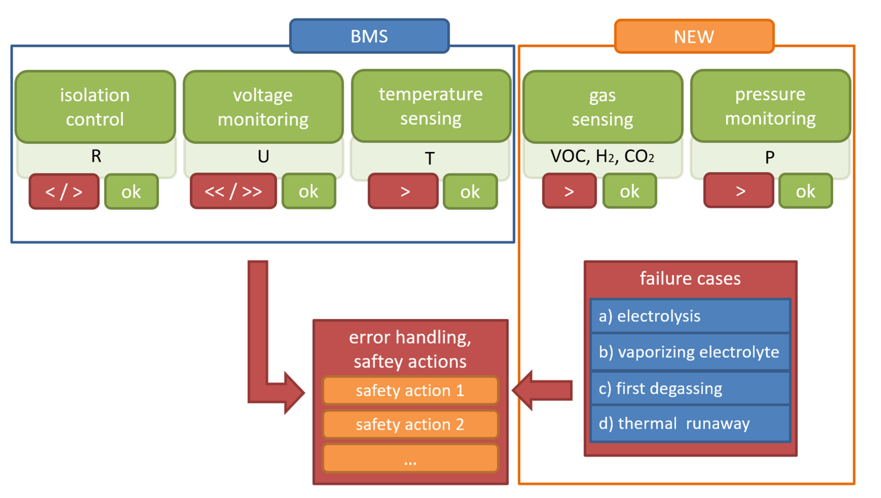
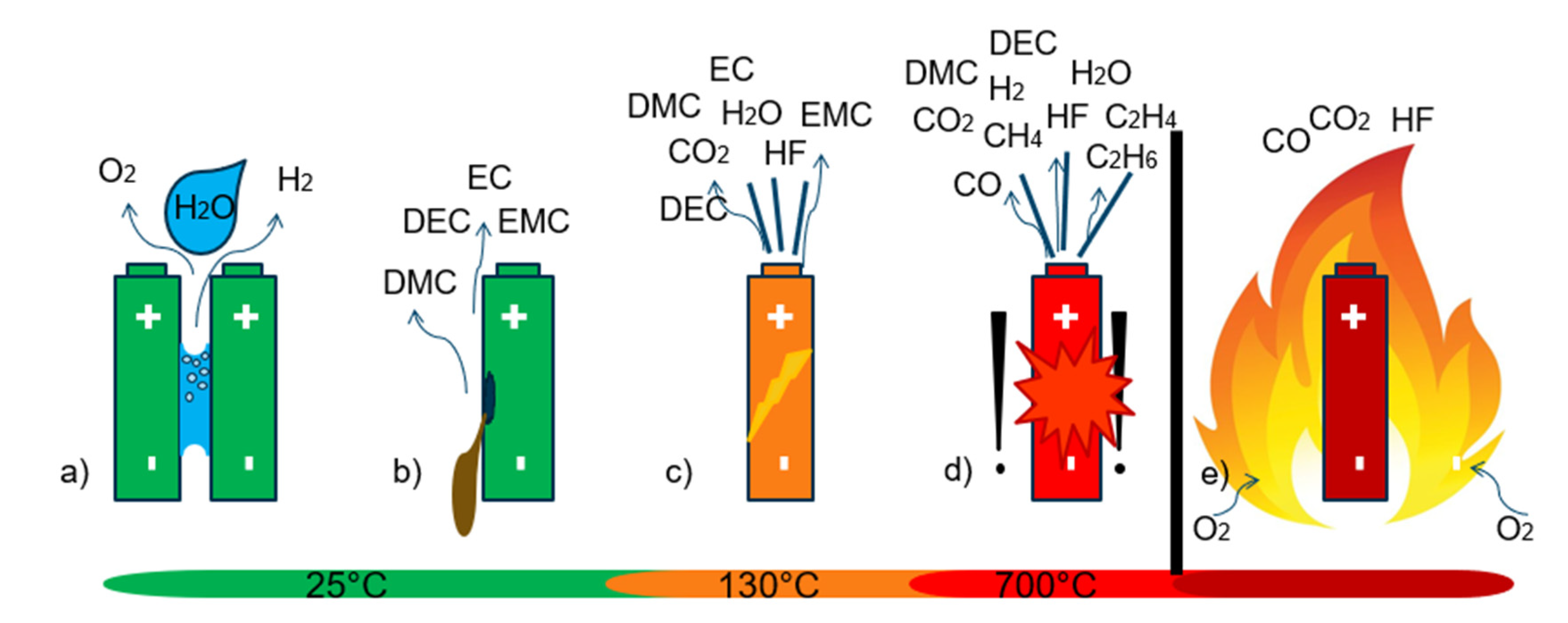
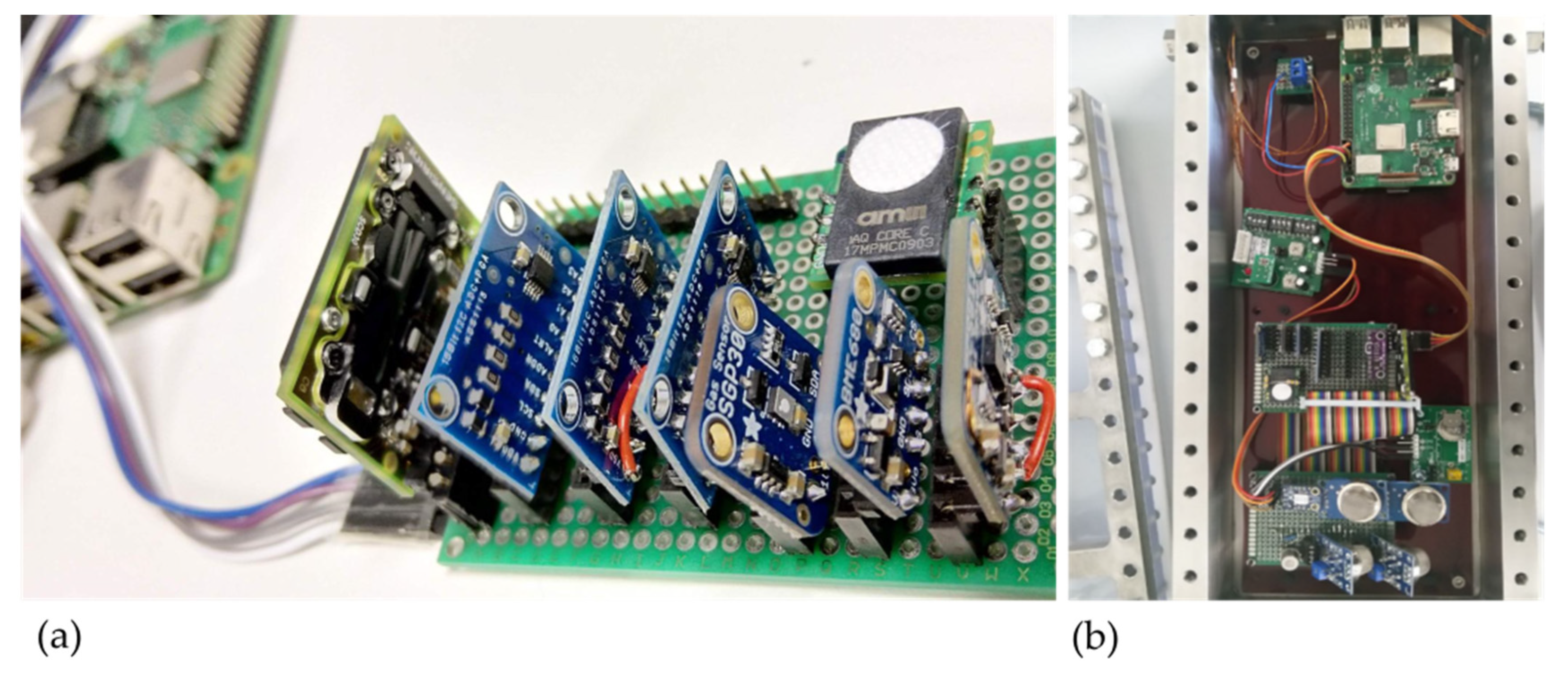
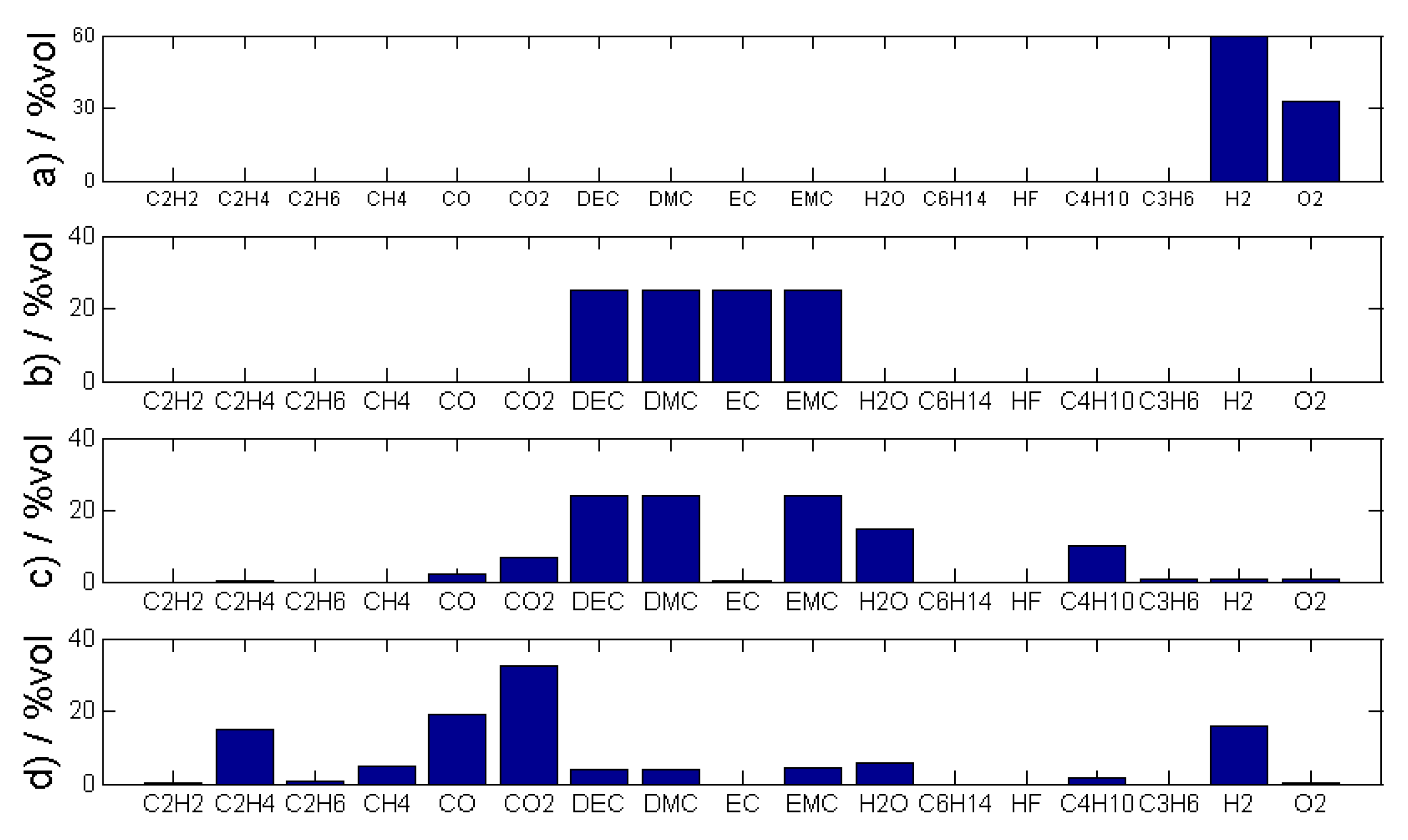
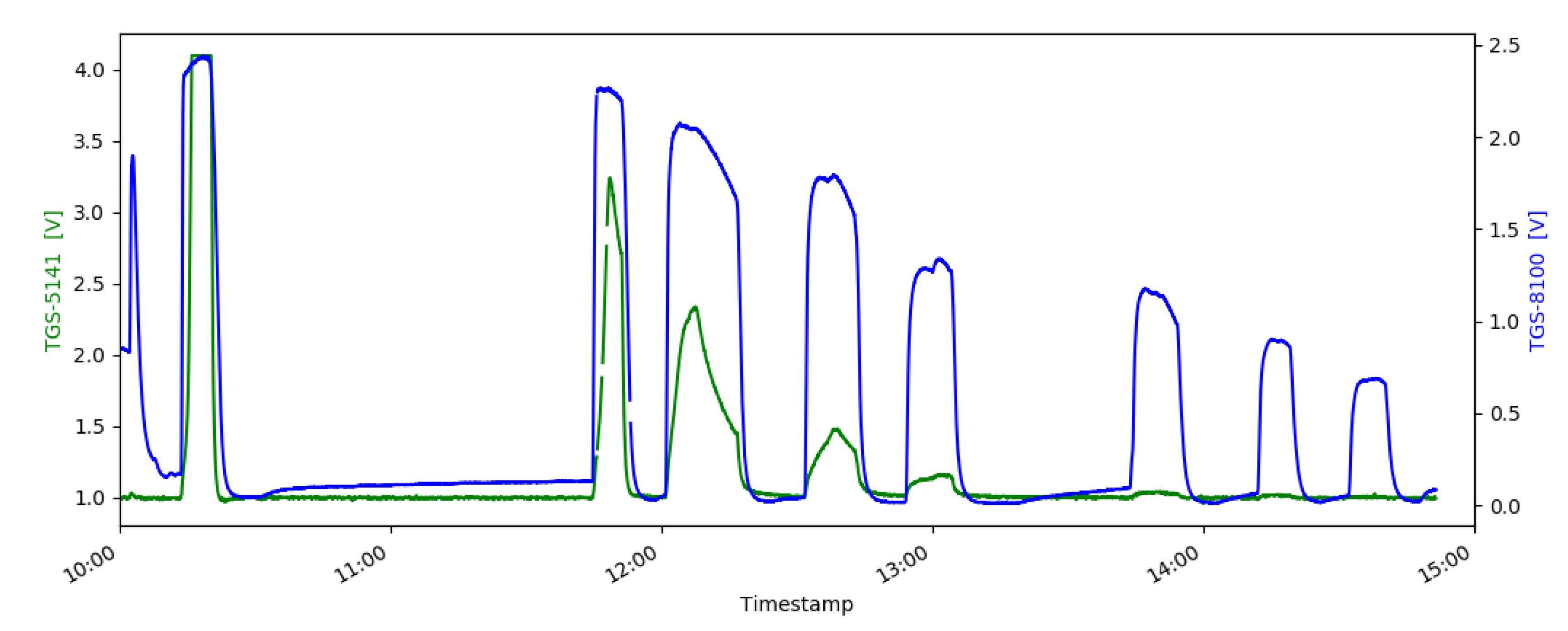
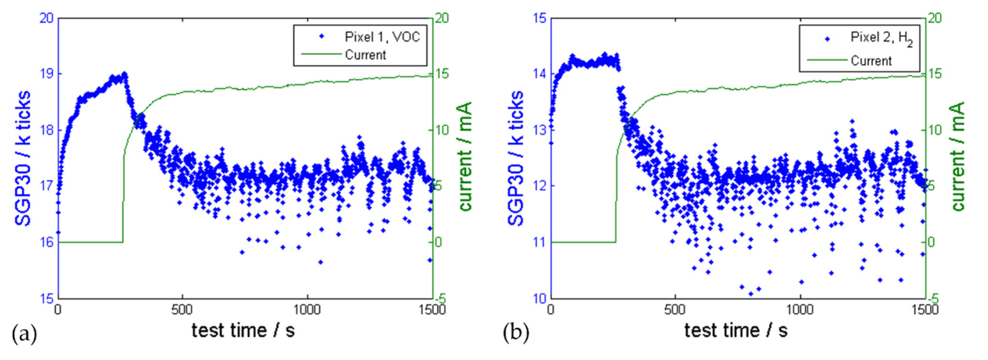
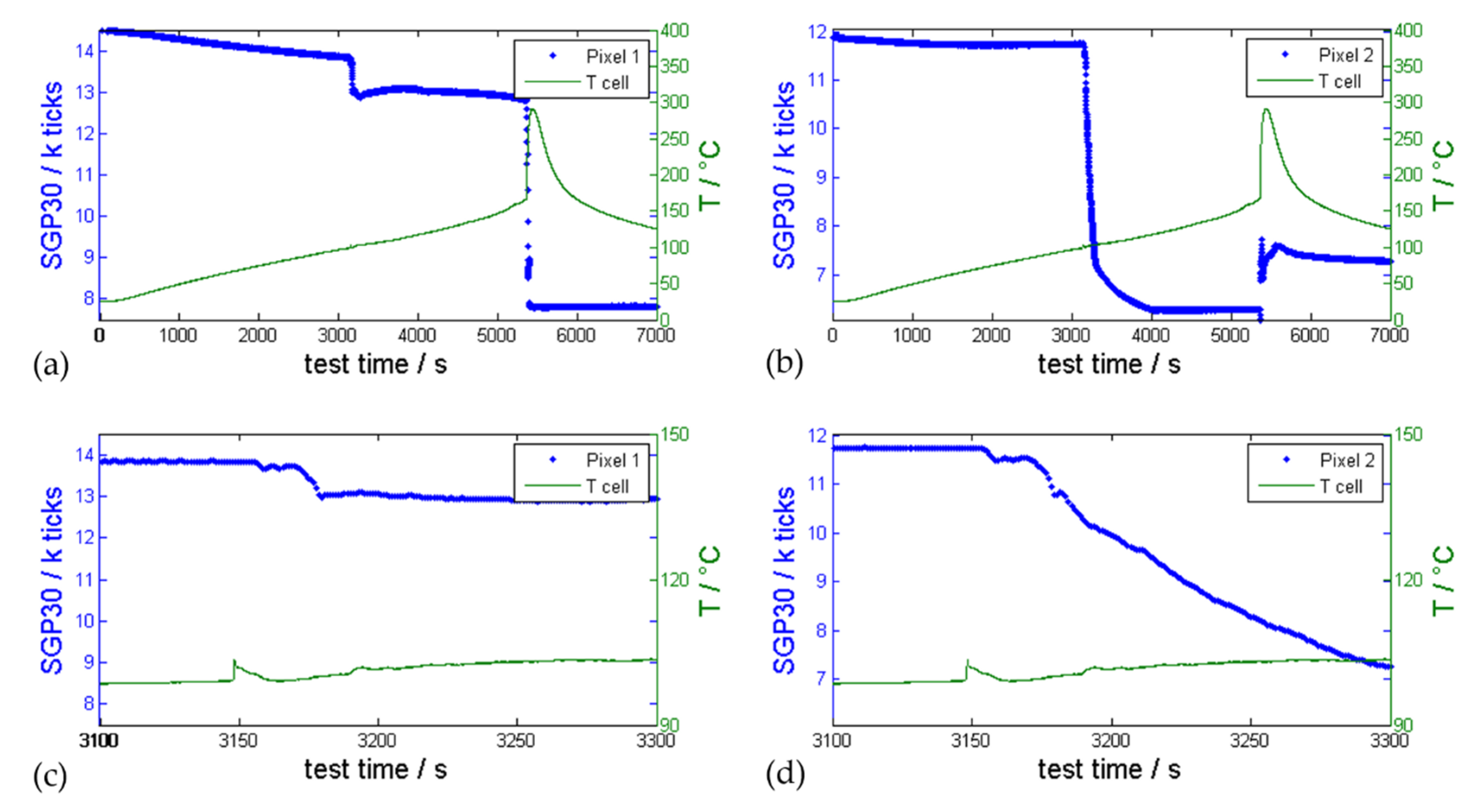
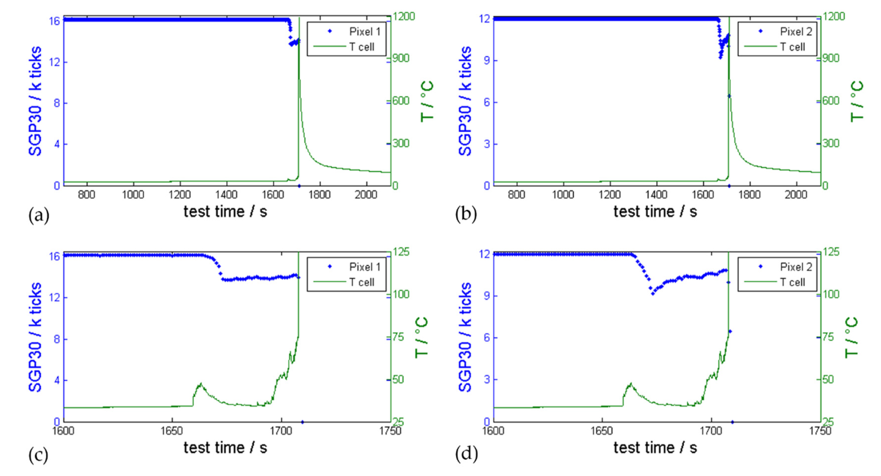
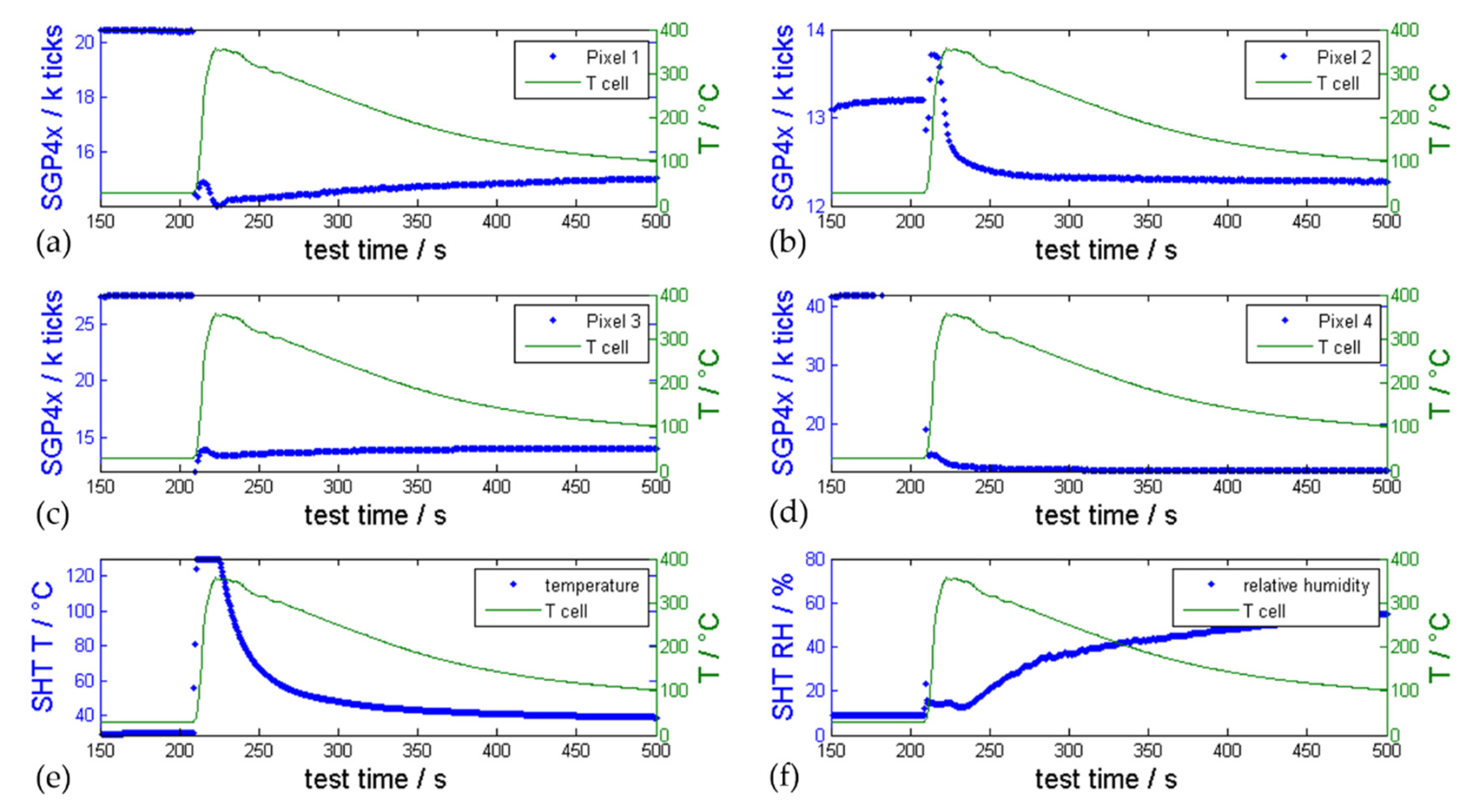
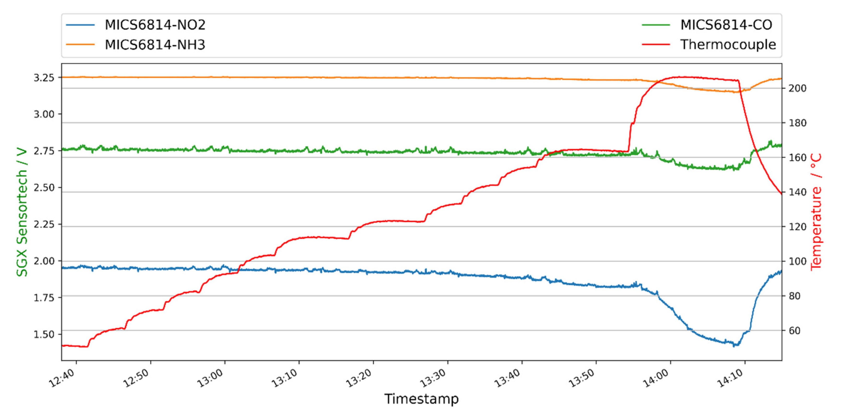
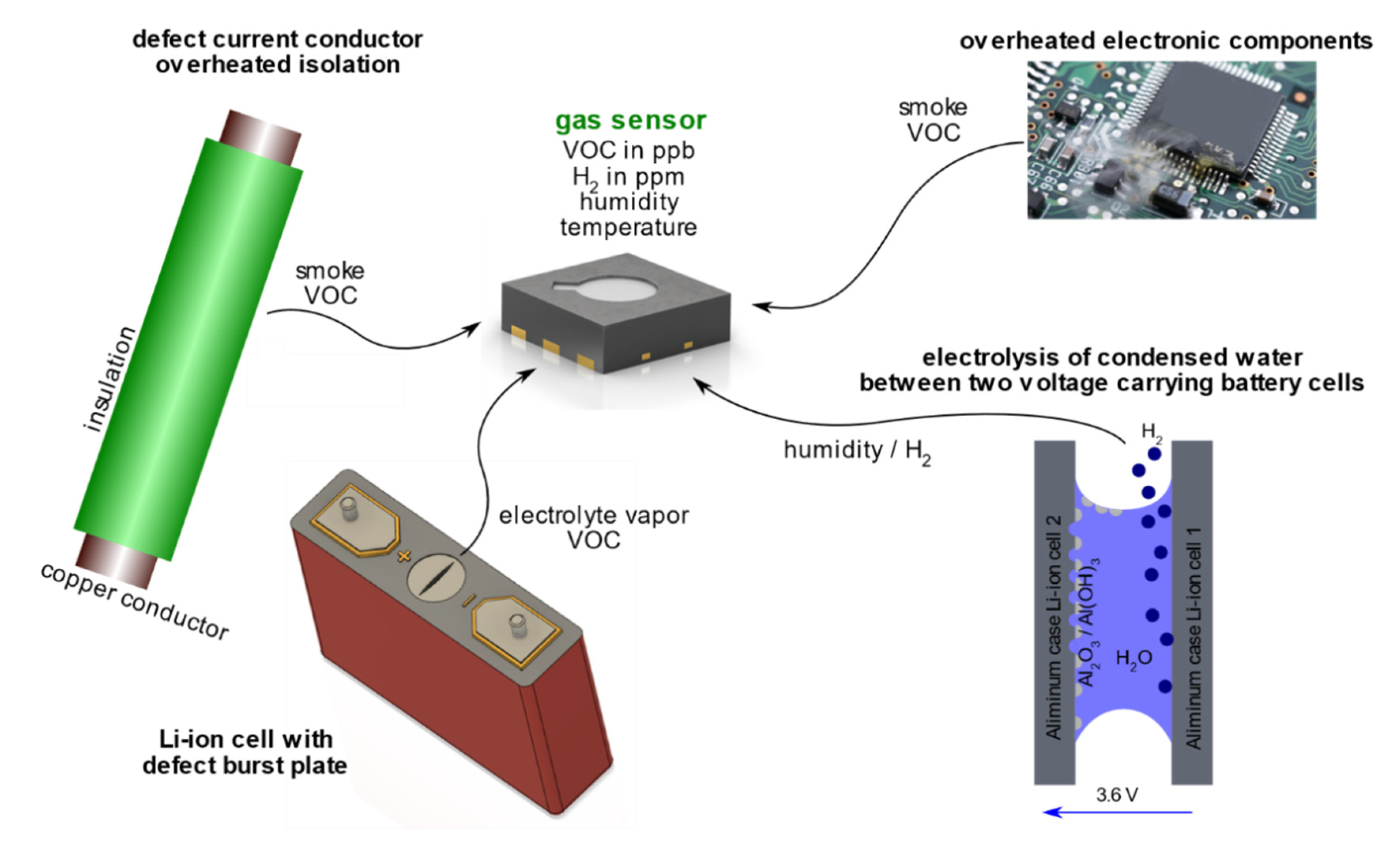
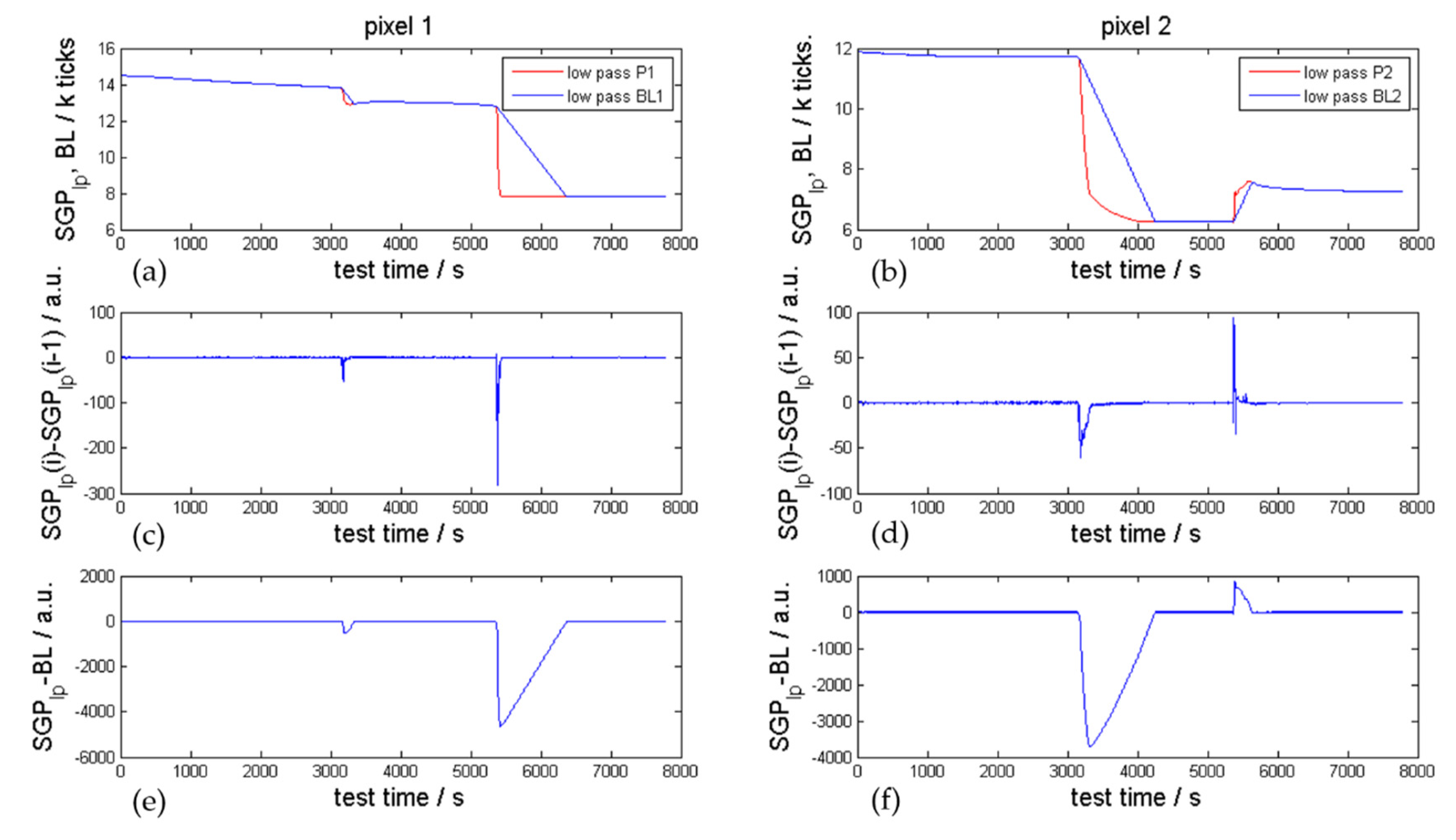
Table 1.
Specification of the investigated automotive Li-ion cells.
| Parameter | Cell Type #1 | Cell Type #2 | Cell Type #3 | Cell Type #4 |
|---|---|---|---|---|
| type | pouch | prismatic hard case | pouch | pouch |
| cathode material | NMC | NMC | NMC/LMO | NMC |
| anode material | graphite | graphite | graphite | graphite /LTO |
| electrolyte | EC:EMC (1:1) | EC:DMC:EMC (2:3:3) | EC:DEC:DMC (12:12:1) | EMC:PC:EC (4:2:1) |
| capacity | 60 Ah | 60 Ah | 41 Ah | 37 Ah |
| nominal voltage | 3.6 V | 3.6 V | 3.8 V | 3.6 V |
| gravimetric energy density | 250 Wh/kg | 225 Wh/kg | 180 Wh/kg | 190 Wh/kg |
| electrode design | stacked | 2 jelly rolls | stacked | stacked |
Table 2.
Representative gas components measured in the investigated failure cases including assumed maximum gas amount bases on a failing automotive 60 Ah cell.
Table 2.
Representative gas components measured in the investigated failure cases including assumed maximum gas amount bases on a failing automotive 60 Ah cell.
| Battery Failure Case | (Vent) Gases | Gas Amount / mol | |
|---|---|---|---|
| (a) | electrolysis | H2, O2 | up to 0.013 mol H2/h |
| (b) | electrolyte vapor | electrolyte | up to 1.4 mol |
| (c) | first venting | electrolyte, H2O, CO2, CO, C2H6, H2, C2H4 | up to 1.8 mol |
| (d) | thermal runaway | CO, H2, CO2, H2O, C2H4, CH4, C4H10, C2H6, C2H2, electrolyte | up to 0.11 mol/Ah, for 60 Ah, 7 mol |
Table 3.
Selected and tested sensors for usage as early battery failure detector.
| Sensor | Manufacturer | Sensor Principle | Target Gas |
|---|---|---|---|
| MiCS-5524 | SGX Sensortech | MOx | CO, H2, CH4 |
| MiCS-6814 | SGX Sensortech | MOx | CO, NH3, NOx |
| iAQ-core | AMS | MOx | VOCs |
| CCS811 | AMS | MOx | VOCs |
| TGS 8100 | Figaro | MOx | ethanol, H2 |
| TGS 5141 | Figaro | electrochemical (solid electrolyte) | CO, H2 |
| TGS 2620 | Figaro | MOx | ethanol, H2 |
| MQ-2 | Winsen | MOx | smoke, LPG, ethanol |
| MQ-8 | Winsen | MOx | H2 |
| SCD30 | Sensirion | NDIR, hygrometer, thermometer | CO2 |
| SGP30 | Sensirion | MOx | VOC, H2 |
| SGP4x_eng | Sensirion | MOx | VOC, NOx, VOC, S |
| SGAS701 | IDT | MO | H2 |
| SHT31 | Sensirion | hygrometer, thermometer | water vapor, temperature |
| BME 680 | Bosch | MOx, hygrometer, thermometer, barometer | VOCs, temperature, pressure, water vapor |
| BME 280 | Bosch | hygrometer, thermometer, barometer | temperature, pressure, water vapor |
Table 4.
Overview of the SGP30 signal-to-noise ratios (SNR) measured for the first venting event with event detector ED1 and ED2 in 21 different overtemperature and overcharge TR experiments on large automotive LIBs for pixels 1 and 2.
Table 4.
Overview of the SGP30 signal-to-noise ratios (SNR) measured for the first venting event with event detector ED1 and ED2 in 21 different overtemperature and overcharge TR experiments on large automotive LIBs for pixels 1 and 2.
| Experiment NR. | 1 | 2 | 3 | 4 | 5 | 6 | 7 | 8 | 9 | 10 | 11 | 12 | 13 | 14 | 15 | 16 | 17 | 18 | 19 | 20 | 21 | |
|---|---|---|---|---|---|---|---|---|---|---|---|---|---|---|---|---|---|---|---|---|---|---|
| ED1 | Pixel 1 | |||||||||||||||||||||
| Pixel 2 | ||||||||||||||||||||||
| ED2 | Pixel 1 | |||||||||||||||||||||
| Pixel 2 | ||||||||||||||||||||||
| SNR | >100 | >20 | >10 | >5 | ||||||||||||||||||
Table 5.
Detectability of listed battery failure cases with different tested sensors and sensor principles.
Table 5.
Detectability of listed battery failure cases with different tested sensors and sensor principles.
| Principle | Example | Electrolysis | Electrolyte | 1st venting | TR |
|---|---|---|---|---|---|
| MOx | SGP30 | ||||
| electrochemical | TGS 5141 | ||||
| nondispersive infrared sensor (NDIR) (CO2) | MH-Z16 | ||||
| hygrometer | SHT31 | ||||
| Fourier-transform infrared spectrometer (FTIR) | Bruker | ||||
| gas chromatograph (GC) | Agilent | ||||
| voltage | |||||
| current | |||||
| temperature | |||||
| detectable | |||||
| unlikely detectable | |||||
| not detectable | |||||
Publisher’s Note: MDPI stays neutral with regard to jurisdictional claims in published maps and institutional affiliations. |
© 2021 by the authors. Licensee MDPI, Basel, Switzerland. This article is an open access article distributed under the terms and conditions of the Creative Commons Attribution (CC BY) license (https://creativecommons.org/licenses/by/4.0/).
Share and Cite
MDPI and ACS Style
Essl, C.; Seifert, L.; Rabe, M.; Fuchs, A. Early Detection of Failing Automotive Batteries Using Gas Sensors. Batteries 2021, 7, 25. https://0-doi-org.brum.beds.ac.uk/10.3390/batteries7020025
AMA Style
Essl C, Seifert L, Rabe M, Fuchs A. Early Detection of Failing Automotive Batteries Using Gas Sensors. Batteries. 2021; 7(2):25. https://0-doi-org.brum.beds.ac.uk/10.3390/batteries7020025
Chicago/Turabian StyleEssl, Christiane, Lauritz Seifert, Michael Rabe, and Anton Fuchs. 2021. "Early Detection of Failing Automotive Batteries Using Gas Sensors" Batteries 7, no. 2: 25. https://0-doi-org.brum.beds.ac.uk/10.3390/batteries7020025
Note that from the first issue of 2016, this journal uses article numbers instead of page numbers. See further details here.