
Robust 3D Object Model Reconstruction and Matching for Complex Automated Deburring Operations

Abstract
:
1. Introduction
2. State of the Art and Previous Related Works
3. Problem Definition


| Zone in Sample Part | Burr Thickness (mm) |
|---|---|
| 1 | 3 |
| 2 | 3 |
| 3 | 1.5 |
| 4 | 1.4 |
| 5 | 1.7 |
| 6 | 0.25 |
| 7 | 1.6 |
| 8 | 1.6 |
| 9 | 1.2 |
| 10 | 0.9 |
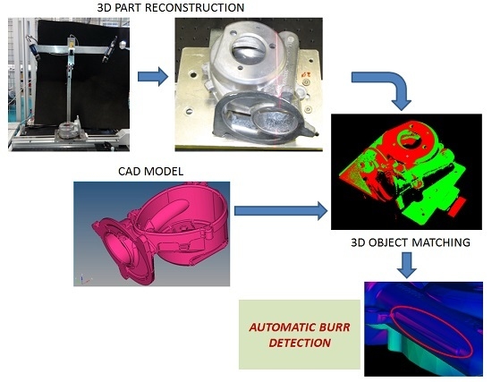
4. Methods
- 3D reconstruction of the part, using sheet of light techniques and registration methods to obtain a point cloud volume avoiding shadows and occlusions.
- Point cloud filtering and clustering to obtain a robust model of the part under inspection.
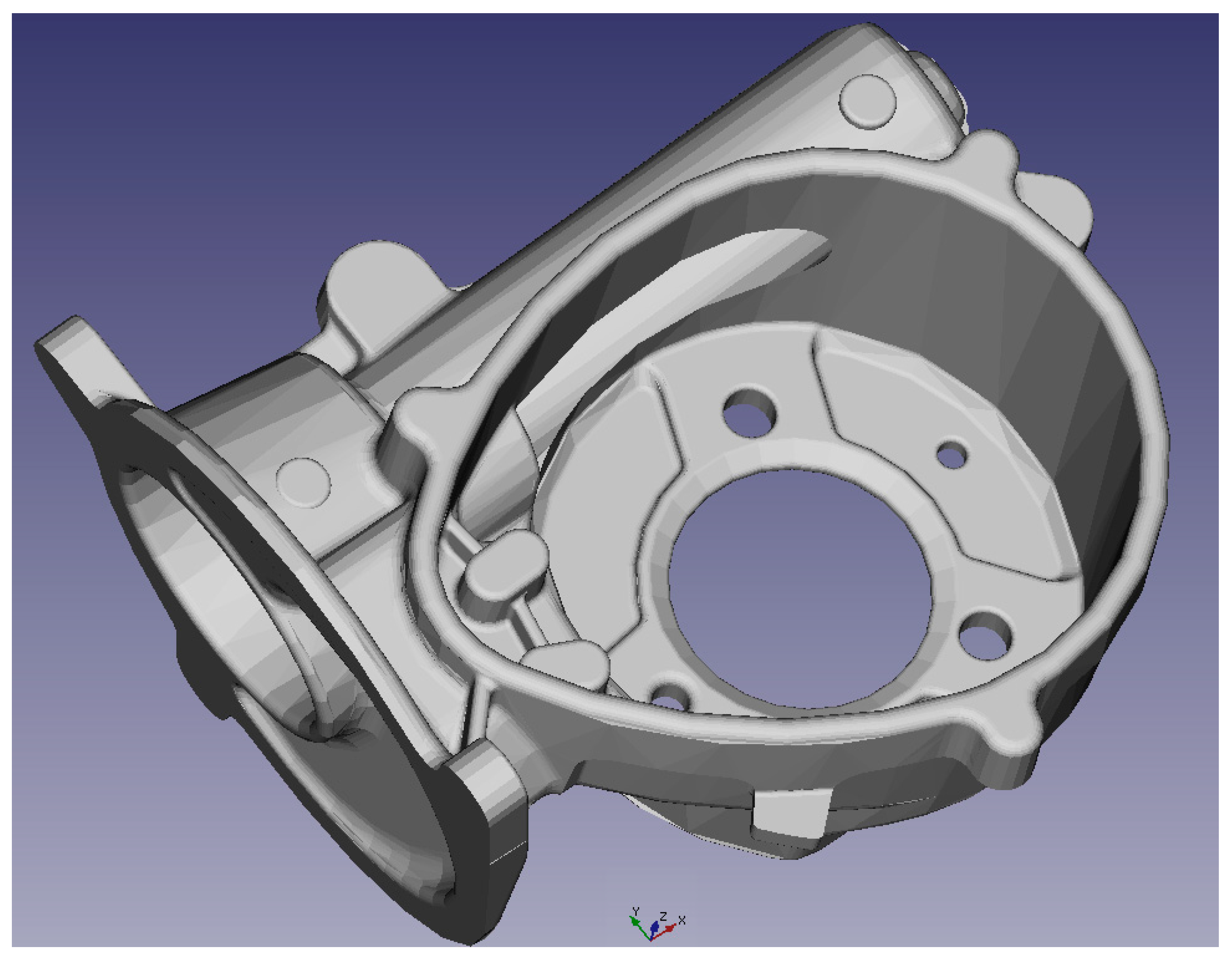
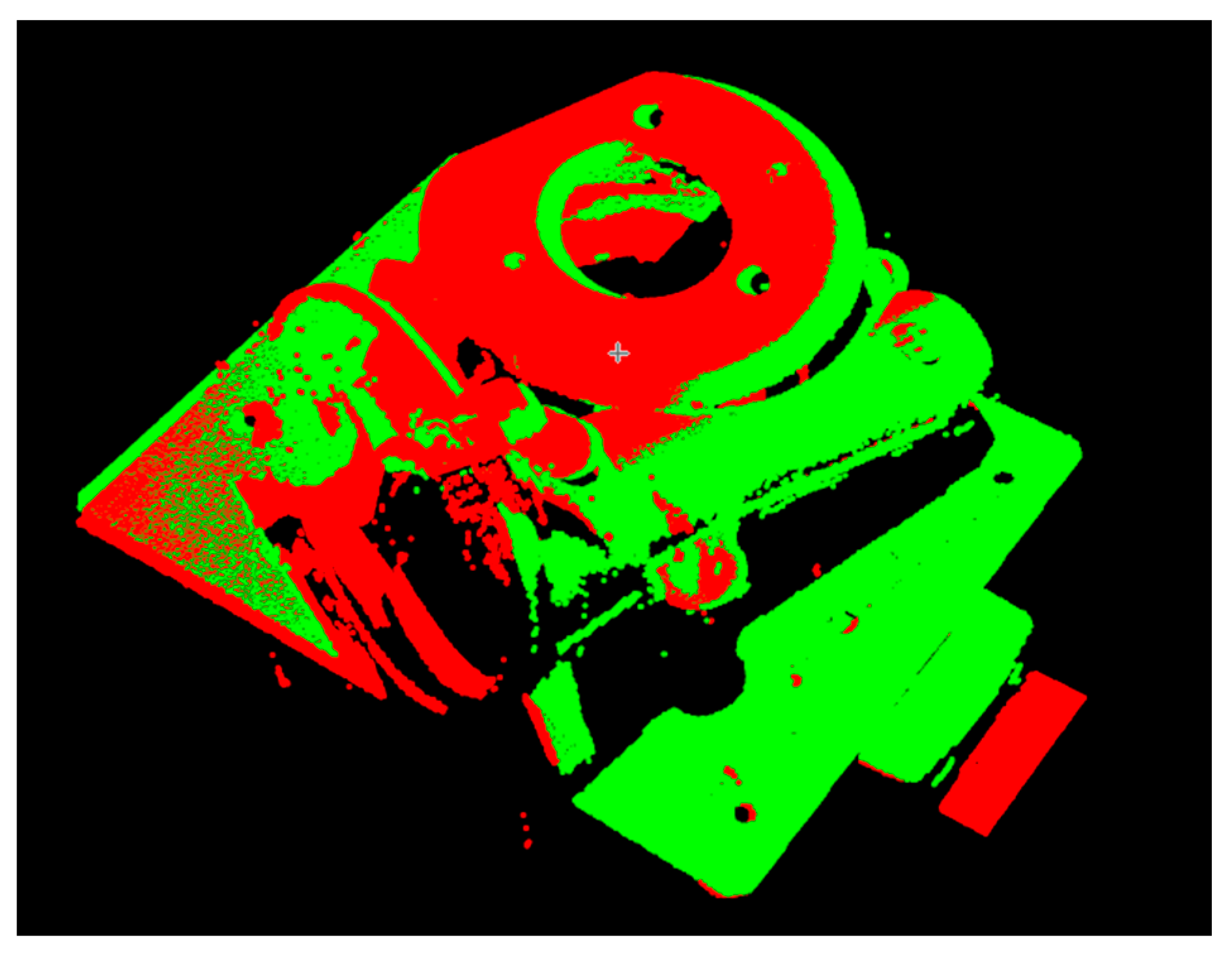
- Matching with the identified part CAD model, STL file in this case, to obtain volume differences corresponding to burrs.
4.1. 3D Reconstruction and Partial View Registration

- Two Dalsa Genie HM1400 matricial cameras, with a 1400 × 1280 pixel sensor, with a pixel size of 7.4 μm, and up to 75 fps. The image output format is GigE Vision.
- High resolution optics, f 1.4, with a focal length of 16 mm.
- Lasiris SLH-501L red laser line generator, with a 30° fan angle.
- Working area of 200 mm in x axis. Y axis obtained by camera triggering.
- System calibrated in X and Z using 100 × 100 mm squared calibration plate. Optimum height resolution has been found with a value of α = 30°.
- The relative movement is carried out using a SMC LEFS32S3A linear axis with a 600 mm moving range and a resolution of 0.02 mm, commanded by a SMC LEC SA2-S3 servo motor.

4.2. Point Cloud Preprocessing
- Outlier removal: Using the euclidean distance as measuring criterium, an outlier in the point cloud is defined as a point whose mean distance to the k nearest neighbours is bigger than D mm, with k = 3 and D = 5.
- Downsampling using a voxel grid filter: All the points within voxel cubes of d mm of edge, are substituted by a new point, the cube centroid. Voxel cubes containing less than n points are removed from the point point cloud. d = 0.5 mm, n = 5 points.
- Smoothing of the downsampled pointcloud: For point cloud smoothing the MLS algorithm is used, and fits a planar surface or a higher order polynomial surface to its k nearest points. The surface fitting is a standard weighted least squares parameter estimation of the plane or polynomial surface parameters, respectively. The closest neighbors of P have higher contribution than the other points, which is controlled by the following weighting function with a parameter ⱷ:

4.3. Matching with CAD Model and Burr Detection

5. Results
| - | Burr Type | |||||||||||||||||||
|---|---|---|---|---|---|---|---|---|---|---|---|---|---|---|---|---|---|---|---|---|
| Part N. | 1 | 2 | 3 | 4 | 5 | 6 | 7 | 8 | 9 | 10 | ||||||||||
| 1 | 2.9 | 3 | 2.7 | 2.8 | 1.8 | 1.8 | - | - | 2.1 | 2 | 0.5 | 0.5 | 1.5 | 1.6 | 1.5 | 1.5 | - | - | 0.9 | 1 |
| 2 | 2.9 | 2.8 | - | - | 1.4 | 1.5 | 1.3 | 1.4 | 2 | 2.1 | 0.7 | 0.7 | - | - | 1.1 | 1.3 | - | - | ||
| 3 | 3 | 2.9 | 2.9 | 2.7 | - | - | 1.8 | 1.7 | 2.1 | 2.2 | - | - | 1.7 | 1.7 | 1.7 | 1.8 | 1.7 | 1.7 | 1.2 | 1.2 |
| 4 | - | - | 3 | 3.1 | 1.6 | 1.7 | 2 | 1.9 | 2.2 | 2 | 0.3 | 0.4 | - | - | 1.5 | 1.6 | 1.3 | 1.3 | ||
| 5 | 2.8 | 3 | - | - | - | - | 2.3 | 2.3 | - | - | 1.6 | 1.7 | 1.6 | 1.7 | - | - | 1.1 | 1.2 | ||
| 6 | 3 | 3.1 | 3.2 | 3.2 | 1.6 | 1.4 | 1.6 | 1.6 | 2.2 | 2.2 | 0.7 | 0.5 | 1.5 | 1.5 | 1.4 | 1.4 | 1.6 | 1.5 | 1 | 0.9 |
| 7 | 2.9 | 2.8 | 2.6 | 2.7 | - | - | 1.5 | 1.5 | 2 | 2.1 | 0.5 | 0.3 | 1.8 | 1.8 | - | - | 1.8 | 1.7 | 1 | 1.1 |
| 8 | 2.9 | 2.7 | 2.6 | 2.6 | 2 | 1.9 | 1.7 | 1.8 | 2 | 2.1 | 0.5 | 0.5 | 1.4 | 1.4 | 1.7 | 1.6 | 1.8 | 1.6 | 0.9 | 1 |
| 9 | 3 | 3.1 | 3 | 3 | 1.7 | 2 | 1.7 | 1.7 | - | - | 0.7 | 0.6 | 1.6 | 1.7 | 1.8 | 1.9 | - | - | 1 | 0.8 |
| 10 | - | - | - | - | 1.9 | 1.8 | 1.4 | 1.3 | 2.3 | 2.4 | 0.3 | 0.4 | 1.6 | 1.6 | 1.6 | 1.5 | 1.5 | 1.5 | 1.3 | 1.3 |
| Burr Type | Mean Measured Thickness (mm) | Mean Real Thickness (mm) | Mean Error (mm) | Error Percentage over Real Measurement (%) |
|---|---|---|---|---|
| 1 | 2.9 | 3 | −0.1 | 3 |
| 2 | 3 | 3 | 0 | 0 |
| 3 | 1.5 | 1.6 | −0.1 | 6 |
| 4 | 1.6 | 1.7 | −0.1 | 6 |
| 5 | 2.0 | 2.2 | −0.2 | 9 |
| 6 | 0.6 | 0.8 | −0.2 | 25 |
| 7 | 1.5 | 1.5 | 0 | 0 |
| 8 | 1.6 | 1.7 | −0.1 | 5 |
| 9 | 1.3 | 1.4 | −0.1 | 7 |
| 10 | 1 | 1 | 0 | 0 |
6. Conclusions and Future Work
- The thickness measured in the burrs is always smaller than the real thickness. This is important to avoid an excessive deburring of the part, compromising its mechanical properties.
- The errors in measurements are proportionally much bigger when the burr size is smaller, however, never bigger than 0.2, an admissible tolerance for general deburring applications.
- All the burr types defined in the reference part are correctly detected and with measurement errors smaller than 0.2, a tolerance that assesses the validation of this setup for industrial use in automatic deburring stations.
- Obtaining a more compact system, to be able to mount the complete set up as a robot tool.
- Substitution of the linear axis by a small working area robot. With this new setup, any complex part could be scanned and reconstructed from different and variable angles, avoiding shadows and occlusions. In this case, precise calibration of the working area of the robot would be needed so that precise affine transformations could be done to the obtained partial point clouds, before proceeding to the global registration of them all to obtain the part surface model.
Acknowledgments
Author Contributions
Conflicts of Interest
References
- Lee, S.H. Deburring Automation and Precision Laser Deburring; University of California: Berkeley, CA, USA, 1996. [Google Scholar]
- Lee, S.H.; Dornfeld, D.A. Precision laser deburring. J. Manuf. Sci. Eng. 2001, 123, 601–608. [Google Scholar]
- Petring, D.; Abels, P.; Noldechen, E.; Presing, K.U. Laser beam cutting of highly alloyed thick section steels. In Laser/Optoelectronics in Engineering; Springer Verlag: Berlin, Germany, 1990; pp. 599–604. [Google Scholar]
- Sato, S.; Takahashi, K.; Saito, S.; Fujioka, T.; Noda, O.; Kuribayashi, S.; Imatake, S.; Kondo, M. Five-kilowatt highly efficient electric discharge cw CO laser. In Proceedings of the Conference on Lasers and Electro-Optics, Baltimore, MD, USA, 24–28 April 1989.
- Jones, M.; Chen, X. Thick section cutting with a high brightness solid state laser. In Proceedings of the 1999 Laser Materials Processing Conference (ICALEO ‘99), Orlando, FL, USA, 1999; pp. A158–A165.
- Alfille, J.P.; Pilot, G.; Prunele, D. New pulsed YAG laser performances in cutting thick metallic materials for nuclear applications. In High Power Lasers: Applications and Emerging Applications; SPIE: Bellingham, WA, USA, 1996; pp. 134–144. [Google Scholar]
- Kar, A.; Scott, J.E.; Latham, W.P. Theoretical and experimental studies of thick-section cutting with a chemical oxygen-iodine laser (COIL). J. Laser Appl. 1996, 8, 125–133. [Google Scholar]
- Adams, M.J. Processes Introduction to Gas Jet Laser Cutting. Met. Constr. Br. Weld. J. 1970, 2, 1–8. [Google Scholar]
- Carrol, D.L.; Kar, J.A.; Latham, W.L. Experimental analysis of the materials processing performance of Chemical Oxygen-Iodine Laser (COIL). In Proceedings of the Laser Materials Processing Conference (ICALEO ’96), Orlando, FL, USA, 1996; pp. 19–27.
- Juckenath, B.; Bergmann, H.W.; Geiger, M.; Kupfer, R. Cutting of aluminium and titanium alloys by CO2 lasers. In Laser/Optoelectronics in Engineering; Springer Verlag: Berlin, Germany, 1990; pp. 595–598. [Google Scholar]
- Powell, J. C02 Laser Cutting; Springer: London, UK, 1998. [Google Scholar]
- Bod, D.; Brasier, R.E.; Parks, J. A powerful CO2 cutting tool. Laser Focus 1969, 5, 36–38. [Google Scholar]
- Shigematsu, I.; Kozuka, T.; Kanayama, K.; Hirai, Y.; Nakamura, M. Cutting of TiAl intermetallic compound by CO2 laser. J. Mater. Sci. Lett. 1993, 12, 1404–1407. [Google Scholar]
- Daurelio, G. Copper sheets laser cutting: a new goal on laser material processing. In Proceedings of the 1987 Conference Laser Advanced Materials Processing (LAMP ‘87), Osaka, Japan, 21–23 May 1987; pp. 261–266.
- Pocklington, D.N. Application of lasers to cutting copper and copper alloys. Mater. Sci. Technol. 1989, 5, 77–86. [Google Scholar] [CrossRef]
- Powell, J.; King, T.G.; Menzies, I.A.; Frass, K. Optimization of pulsed laser cutting of mild steels. In Proceedings of the 3th International Congress on Lasers in Manufacturing; Springer Verlag: Paris, France, 1986; pp. 67–75. [Google Scholar]
- Lunau, F.W.; Paine, E.W. CO2 laser cutting. Weld. Met. Fabr. 1969, 27, 3–8. [Google Scholar]
- Chui, G.K. Laser cutting of hot glass. Am. Ceram. Soc. Bull. 1975, 54, 515–518. [Google Scholar]
- Dobbs, R.; Bishop, P.; Minardi, A. Laser Cutting of Fibrous Quartz Insulation Materials. J. Eng. Mater. Technol. 1994, 116, 539–544. [Google Scholar] [CrossRef]
- Kawaga, Y.; Utsunomiya, S.; Kogo, Y. Laser cutting of CVD-SiC fibre/A6061 composite. J. Mater. Sci. Lett. 1989, 8, 681–683. [Google Scholar] [CrossRef]
- Rieck, K. Laser cutting of fiber reinforced materials. In Proceedings of the 3rd European Conference Laser Treatment of Materials (ECLAT ‘90), Coburg, Germany, 17–19 September 1990; pp. 777–788.
- Andreopoulos, A.; Tsotsos, J.K. 50 Years of object recognition: Directions forward. Comput. Vis. Image Underst. 2013, 117, 827–891. [Google Scholar] [CrossRef]
- Ekvall, S.; Kragic, D.; Hoffmann, F. Object recognition and pose estimation using color cooccurrence histograms and geometric modeling. Image Vis. Comput. 2005, 23, 943–955. [Google Scholar] [CrossRef]
- Eggert, D.W.; Fitzgibbon, A.W.; Fisher, R.B. Simultaneous registration of multiple range views for use in reverse engineering of CAD models. Comput. Vis. Image Underst. 1998, 69, 253–272. [Google Scholar] [CrossRef]
- Fitzgibbon, A.W. Robust registration of 2D and 3D point sets. Image Vis. Comput. 2003, 21, 1145–1153. [Google Scholar] [CrossRef]
- Beserra, R.; Marques, B.; Karin de Medeiros, L.; Vidal, R.; Pacheco, L.C.; Garcia, L.M. Efficient 3D object recognition using foveated point clouds. Comput. Graph. 2013, 37, 496–508. [Google Scholar] [CrossRef]
- Aldoma, A.; Vincze, M.; Blodow, N.; Gossow, D.; Gedikli, S.; Rusu, R.B.; Bradski, G. CAD-model recognition and 6DOF pose estimation using 3D cues. In Proceedings of the 2011 IEEE International Conference on Computer Vision Workshops (ICCV Workshops), Barcelona, Spain, 6–13 November 2011; pp. 585–592.
- Morency, L.; Sundberg, P.; Darrell, T. Pose estimation using 3D view-based eigenspaces. In Proceedings of the 2003 IEEE International Workshop on Analysisn and Modeling of Faces and Gestures, Nice, France, 17 October 2003; pp. 45–52.
- Rusu, R.B.; Bradski, G.; Thibaux, R.; Hsu, J. Fast 3D recognition and pose using the Viewpoint Feature Histogram. In Proceedings of the 2010 IEEE International Conference on Intelligent Robots and systems (IROS), Taipei, Taiwan, 10–12 October 2010; pp. 2155–2162.
- Azad, P.; Asfour, T.; Dillmann, R. Accurate shape-based 6-DoF pose estimation of single-colored objects. In Proceedings of the 2009 IEEE International Conference on Intelligent Robots and Systems (IROS), St. Louis, MO, USA, 10–15 October 2009; pp. 2690–2695.
- Changhyun, C.; Christensen, H.I. Real-time 3D model-based tracking using edge and keypoint features for robotic manipulation. In Proceedings of the 2010 IEEE International Conference on Robotics and Automation (ICRA), New Orleans, LA, USA, 26 April–1 May 2010; pp. 4048–4055.
- Mittrapiyanumic, P.; DeSouza, G.N.; Kak, A.C. Calculating the 3D-pose of rigid-objects using active appearance models. In Proceedings of the 2004 IEEE International Conference on Robotics and Automation (ICRA), 2004; pp. 5147–5152.
- Payet, N.; Todorovic, S. From contours to 3D object detection and pose estimation. In Proceedings of the 2011 IEEE International Conference on Computer Vision (ICCV), Barcelona, Spain, 6–13 November 2011; pp. 983–990.
- Drost, B.; Ulrich, M.; Navab, N.; Ilic, S. Model globally, match locally: Efficient and robust 3D object recognition. In Proceedings of the 2010 IEEE Conference on Computer Vision and Pattern Recognition (CVPR), San Francisco, CA, USA, 13–18 June 2010; pp. 998–1005.
- Mian, A.; Bennamoun, M.; Owens, R. On the Repeatability and Quality of Keypoints for Local Feature-based 3D Object Retrieval from Cluttered Scenes. Int. J. Comput. Vis. 2010, 89, 348–361. [Google Scholar] [CrossRef]
- Gao, Y.; Wang, M.; Zha, Z.J.; Tian, Q.; Dai, Q.; Zhang, N. Less is More: Efficient 3-D Object Retrieval With Query View Selection. IEEE Trans. Multimed. 2011, 13, 1007–1018. [Google Scholar] [CrossRef]
- Tombari, F.; Salti, S.; Di Stefano, L. A combined texture-shape descriptor fon enhanced 3D feature matching. In Proceedings of the 18th International Conference on Image Processing, Brussels, Belgium, 11–14 September 2011; pp. 809–812.
- Boehnke, K.E. Hierarchical Object Localization for Robotic Bin Picking. Ph.D. Thesis, Faculty of Electronics and Telecommunications, Politehnica University of Timisoara, Timisoara, Romania, September 2008. [Google Scholar]
- Lowe, D.G. Object recognition from local scale-invariant features. In Proceedings of the Seventh IEEE International Conference on Computer Vision, Kerkyra, Greece, 20–27 September 1999; pp. 1150–1157.
- Muja, M.; Lowe, D.G. Fast Approximate Nearest Neighbors with Automatic Algorithm Configuration. In Proceedings of the 2009 International Conference on Computer Vision Theory and Applications (VISAPP’09), Lisboa, Portugal, 5–8 February 2009.
- Besl, P.J.; McKay, N.D. A Method for Registration of 3-D Shapes. IEEE Trans. Pattern Anal. Mach. Intell. 1992, 14, 239–256. [Google Scholar] [CrossRef]
© 2016 by the authors; licensee MDPI, Basel, Switzerland. This article is an open access article distributed under the terms and conditions of the Creative Commons by Attribution (CC-BY) license (http://creativecommons.org/licenses/by/4.0/).
Share and Cite
Tellaeche, A.; Arana, R. Robust 3D Object Model Reconstruction and Matching for Complex Automated Deburring Operations. J. Imaging 2016, 2, 8. https://0-doi-org.brum.beds.ac.uk/10.3390/jimaging2010008
Tellaeche A, Arana R. Robust 3D Object Model Reconstruction and Matching for Complex Automated Deburring Operations. Journal of Imaging. 2016; 2(1):8. https://0-doi-org.brum.beds.ac.uk/10.3390/jimaging2010008
Chicago/Turabian StyleTellaeche, Alberto, and Ramón Arana. 2016. "Robust 3D Object Model Reconstruction and Matching for Complex Automated Deburring Operations" Journal of Imaging 2, no. 1: 8. https://0-doi-org.brum.beds.ac.uk/10.3390/jimaging2010008