1. Introduction
Encryption is vital for securing the transmission of personal, commercial and governmental data. The rapid development of quantum computation threatens the underpinnings of current public key cryptographic methods, most notably the RSA (Rivest–Shamir–Adelmann) cryptosystem [
1], that are the basis of the internet. Hence, there is the need for the development of “quantum-safe” communication methods that can provide forward security for critical information. We also note the development of “post-quantum cryptography” [
2] that seeks replacement public key algorithms that are resistant to attack by quantum and classical computers. Quantum key distribution (QKD) has been proposed as a solution that allows two distant parties—traditionally named Alice and Bob—to establish a joint secret key of which the security is dependent not on computational complexity assumptions but on the laws of quantum physics. There has been significant effort toward its theoretical and experimental development [
3,
4,
5,
6] over more than three decades, with commercial fibre-based systems now commercially available. However, fibre losses scale exponentially with distance, greatly restricting the range of terrestrial QKD. Conventional optical repeaters cannot be used with QKD [
7,
8,
9] since quantum information cannot be perfectly and deterministically copied [
10,
11] and practical quantum memories are still a long-term prospect. Satellites are currently the only viable option for extending QKD communication ranges beyond distances greater than a few hundred kilometers [
12,
13,
14,
15,
16] and thus for enabling the global quantum internet [
17].
In this article, we present an overview of the quantum research CubeSat (QUARC) space mission and evaluate the feasibility of providing a secure satellite quantum key distribution (SatQKD) service to the UK via a constellation of CubeSats. Another recent work on satellite constellations for QKD networks but with different aims can be found in Reference [
18]. Recently, Satellite quantum communication has witnessed an unprecedented growth including proof-of-principle experiments [
19,
20,
21,
22,
23,
24,
25], quantum mechanics fundamental tests [
26,
27], and the launch and operation of a QKD satellite [
28,
29,
30]. These groundbreaking results have spurred an international space race involving university consortia, national agencies and private companies, e.g., QKDSat (ArQit) [
31], QUARTZ (SES) [
32], QEYSSAT (Canada) [
33], UK–Singapore Bilateral (RAL Space—CQT) [
34], QUBE (Deutsches Zentrum für Luft- und Raumfahrt (DLR) + German Universities) [
35], NANOBOB (Austria–France) [
36] and IOD-6/ROKS (UK) [
37]. Many of these efforts focus on satellites belonging to the domain of large and complex platforms, and little research has been carried out so far regarding QKD performance evaluation using smaller satellites. On the other hand, Small Satellites (SmallSats) and especially the popular CubeSat standard have been in the spotlight for their potential to deliver meaningful communication volumes at a significantly reduced price and complexity. Operationally, they represent a path finder option for the deployment of large constellations offering rapid revisit and therefore greater coverage than a single large spacecraft [
38,
39].
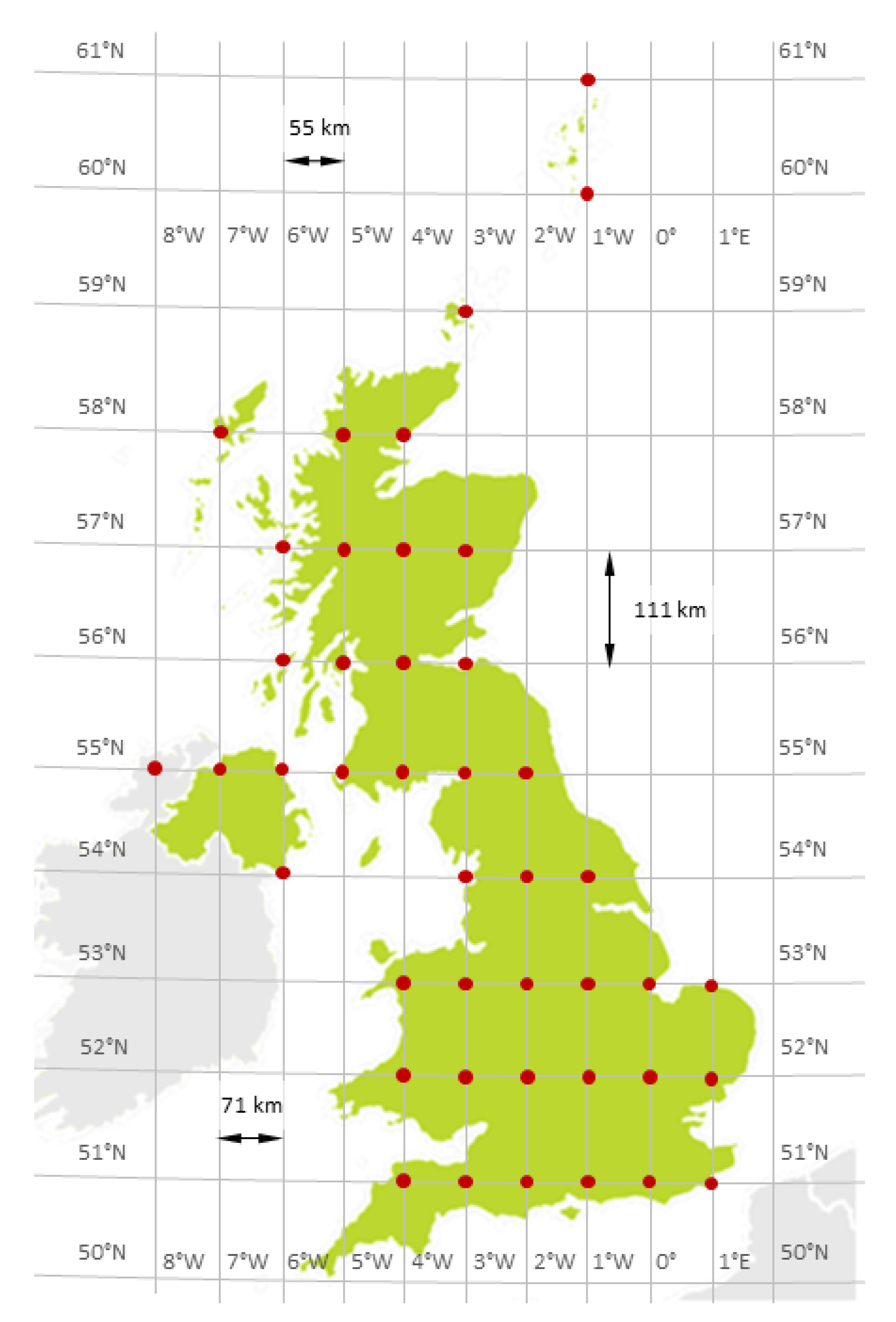
The objective of the QUARC space mission is to provide a QKD service to a specific region: the UK. We identify relationships between satellite constellation topology, the atmospheric channel and historical weather data and estimate key rates over 43 ground stations (gateways) uniformly distributed across the UK (
Figure 1) serviced by a constellation of 15 satellites. These gateway locations cannot be connected currently via the installed fiber network, and they have been defined specifically in order to gain an understanding of how communication performance varies across different regions at different times throughout the year. The aim is not to satisfy a particular revisit/coverage requirement but to offer a generalised performance metric from which performance can be scaled by the number and location of gateways and by the number and distribution of satellites in the constellation. More satellites result in a greater level of expected coverage and secure key, while more gateways result in a higher probability of contact being made and a smaller amount of key data being received at each individual gateway. Here, we have chosen not to focus on the key management and scheduling problems but we refer the reader to recent works on these topics [
40,
41].
The number of keys that can be distributed between the constellation and each gateway throughout the year is evaluated via simulation that incorporates effects from cloud cover, sunrise/sunset, and various sources of losses and spurious counts in order to consider the impact of the changing seasons and latitude. The best case scenario is found to be represented by the southeast England gateway where ∼ 300 kbit/night/satellite of key can be exchanged during August, while the worst case is represented by the northeast islands of Scotland, where no key can be distributed; this is due to the constraint of nighttime operations that we have assumed for the purposes of the analysis. We assume a conservative level of system performance and that daytime background light would result in excessive spurious counts, curtailing operations. We also conservatively assume that QKD operations are not possible in twilight or dusk conditions. In practice, some nonzero key rates may be possible with small levels of background light and a more detailed simulation incorporating site-level background light and astronomical data, e.g., position of the moon, is in development. SatQKD systems that can operate in daytime are currently under development by various groups [
42,
43,
44,
45] but not yet fully demonstrated in orbit. On the other hand, when the constellation is required to distribute keys not only to a single gateway but also to all gateways, the best case scenario secret key volume decreases to 160 kbit/night/satellite, which is also in southeast England. Our results indicate that a CubeSat constellation has the potential to deliver a meaningful amount of secret key for scenarios requiring small-volume, highly secure communication via quantum-resistant symmetric key ciphers like Advanced Encryption Standard (AES) [
46]. We have also carried out preliminary system design and tests of the payload acquisition, pointing and tracking (APT) system, which is a vital subsystem for long-distance free-space QKD; these will be detailed in a separate paper.
The rest of this work is structured as follows: In
Section 2, we outline the payload design, in particular the acquisition pointing and tracking system. In
Section 3, we describe the model for the quantum channel. In
Section 4, we present the mission design and discuss the orbital choice for the satellite constellation. In
Section 5, we model the key exchange between the constellation and the set of gateways.
Section 6 is devoted to the presentation of the mission performance. Finally, this paper concludes with
Section 7.
2. Payload Design and System Outline
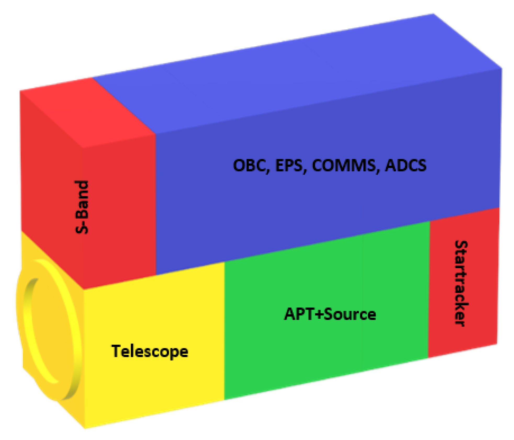
This section gives a brief description of the QKD payload and subsystems used in the mission analysis. A concept outline for the 6U CubeSat is shown in
Figure 2. Such a payload has similarity to free-space optical communication payloads in development for nanosatellite missions [
35,
36,
47] and handheld devices [
48,
49]. SatQKD can be divided into two main types: untrusted and trusted node [
12]. Untrusted node SatQKD ensures verifiable security between two grounds stations via Bell test measurements without any assumption of the security of the satellite itself. This requires simultaneous links between the satellite and the two ground stations, difficult to achieve with high key rates. On the other hand, the trusted node paradigm assumes the satellite to be outside the domain of influence of an eavesdropper. For near-term realisation of SatQKD, the trusted node scenario is thus the most feasible. Trusted node SatQKD can be realised using the spacecraft as a receiver (uplink (UL) configuration) or as a transmitter (downlink (DL) configuration). A DL configuration requires the development of a space-qualified optical assembly for precise pointing of the order of few
rad and quantum sources driven by quantum random number generators [
38,
39]. The UL configuration requires a less complicated payload comprising single photon detectors but would also require a larger telescope compared to DL [
36,
47]. However, in this configuration, the upward beam encounters turbulence early during its path, leading to larger path deviations (the so-called shower curtain effect) and therefore higher losses, on the order of 20 dB greater with respect to the DL configuration [
12,
16,
50,
51]. In this work, we therefore focus attention on the DL scenario.
Quantum Source: QKD requires the ability to send extremely faint pulses of light at a high repetition rate and with a polarization randomly selected from a set of non-orthogonal signal states. This can be achieved by combining multiple differently polarized sources or by modulating the polarization of a single source. Currently, we plan to use multiple polarized LEDs (extinction 1000:1) combined with a single-mode fibre to remove spatial information. LEDs have a wide spectrum, and therefore with appropriate filtering, they are resilient to mismatches in wavelengths between the LEDs. Recent advances in integrated optics could also be leveraged using interferometers to modulate light and 2D grating couplers to generate the polarization states from a single source [
52]. An integrated platform would be smaller but would require additional hardware to monitor the output. Such sources have been previously developed with small size, weight and power (SWaP) envelopes of the orders of
m
3,
kg and
W. They can be made to be monolithic, solid-state devices with further miniaturisation possible through integrated optics fabrication [
53,
54]; hence, the source can be accommodated in 1U. The main issues will be wavelength matching between different emitters to prevent side-channel leakage, modest temperature stability and reliability in the space environment; the latter is still to be proven [
55].
For the source wavelength, we have chosen 808 nm for ease of laser diode selection, atmospheric transmission and low background light during night operations due to atmospheric scattering of moonlight and OH recombination in the upper atmosphere [
56]. We assume a pulse repetition rate of 100 MHz, comparable with QUESS/Micius [
28]) and quite modest compared to what is currently achievable in fiber [
57].
An important aspect of such a source is a supply of truly random and securely generated bits. For a 2-Decoy State Protocol, 4 bits per pulse need to be generated at a rate of 400 Mbps, leading to several tens of gigabytes of random data required for a single pass. For protocols requiring biased basis and signal choices, this will increase the required generation rate. High speed quantum random number generator (QRNGs) with suitable SWaP requirements exist, allowing real-time on-the-fly provision though in-orbit demonstration and validation are still required [
58]. A QKD protocol also requires bidirectional classical communication between Alice and Bob for reconciliation, error correction and privacy amplification which can be performed by RF communications over public channels.
Acquisition, Pointing and Tracking System: In low earth orbit (LEO), the transmission range varies from a few hundred km at zenith up to about 2000 km at low elevations. It is therefore crucial to achieve a pointing accuracy of the order of micro-radians in order to mitigate channel losses. In our system, pointing is achieved in two stages: coarse pointing and fine pointing.
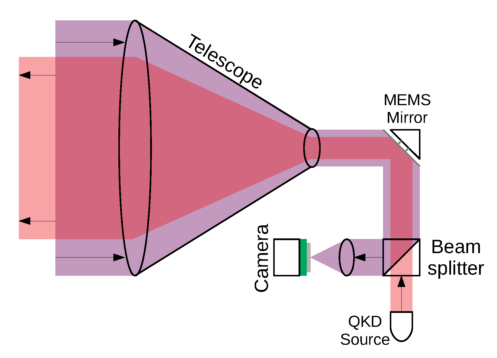
The coarse-pointing stage is provided by pointing the body of the satellite via ADCS and hence the rigidly mounted telescope. Fine pointing is provided by a closed-loop beam steering system using a beacon tracking camera (BTC) and a mems micromirror (MM) (
Figure 3). A MM is a mirror that can be tilted independently over the x and y axes. We have chosen a Mirrorcle S40069 [
59] that has a 5-mm diameter and can be mechanically tilted to up
(optical tilt
) with step of 1.3
rad (the transmission telescope magnification improves this precision by a factor of 30) and is controlled using a software proportional-integral-differential (PID) controller. The quantum signal and both UL and DL beacons are co-aligned on the main boresight of the telescope through in-orbit calibration; these are steered by the MM driven by the output of the BTC. A DL beacon is sent at 905 nm and is coupled into the beam path by a short-pass dichroic mirror, co-aligned with the 808-nm quantum signal. The DL beacon also carries a clock signal synchronised with the 808-nm quantum signal pulses, allowing the optical ground station (OGS) to perform coincidence matching and background event rejection. The UL beacon—chosen to be at 850 nm—is picked out of the beam path by a short-pass dichroic. The image of the UL beacon is focused onto the UL Beacon Camera which is read out at up to 1 kHz in the region-of-interest mode. Preliminary testing indicates that
rad pointing precision is achievable with modest UL beacon power with careful optimisation of the centroiding algorithm parameters.
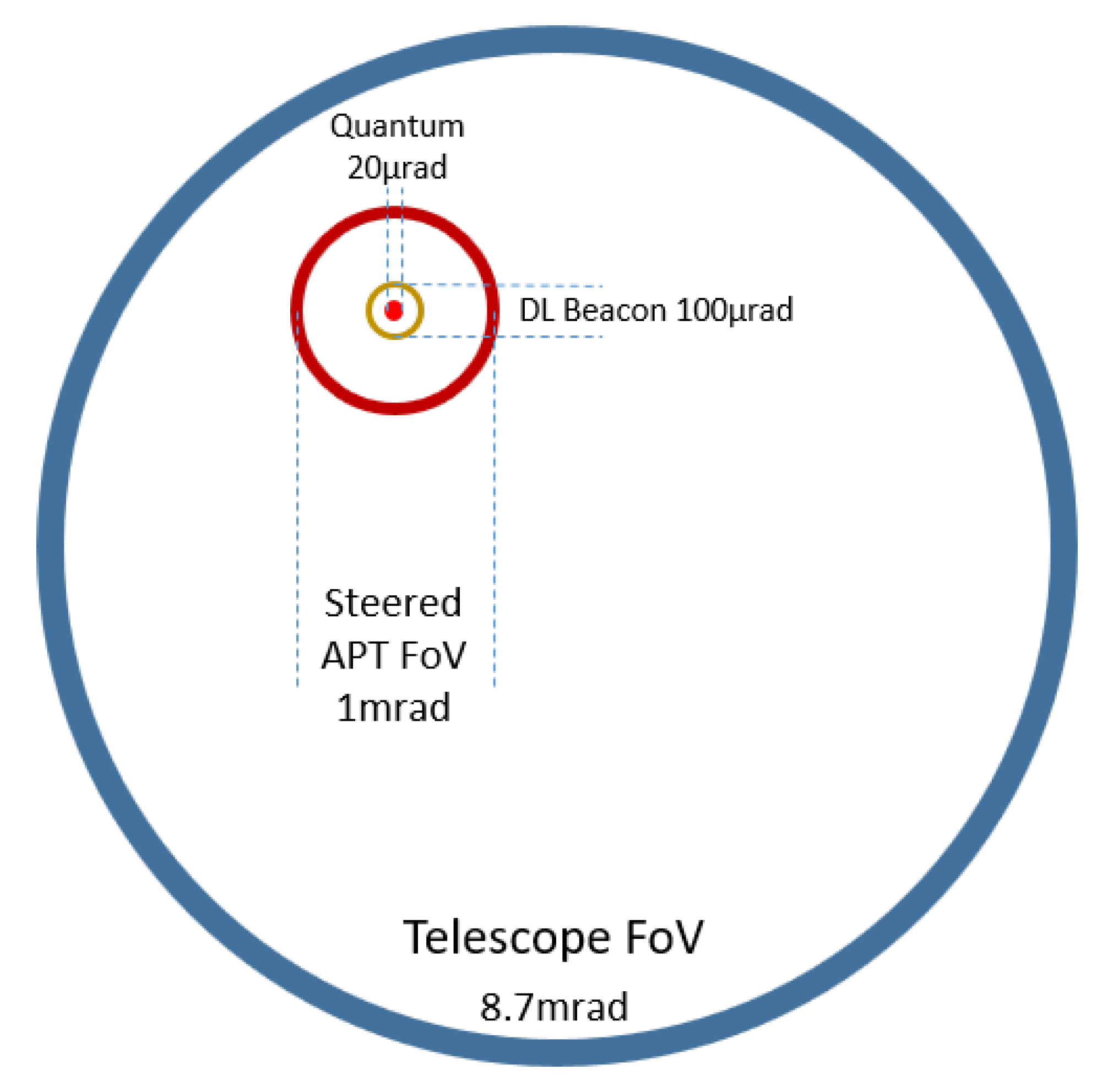
The field of view (FoV) of the UL beacon camera is 5.5 mrad, compared with the telescope FoV 17.5 mrad (
Figure 4). Hence, it is simple to scan the entire telescope FoV using the MM beam steering function for initial acquisition of the UL beacon. In this mode, the beacon spot is simply required to be guided close to the set point; this can be achieved in the time or order of 1 second. After this has been achieved, only a small fraction of the camera sensor needs to be read, which speeds up the tracking loop by up to an order of magnitude.
Once UL beacon lock has been achieved by the fine-pointing mechanism, the deviation of the MM from the neutral position represents a boresight error and this can be fed back to the ADCS to improve coarse pointing. This would allow the reduction of the required telescope FoV that is diffraction limited; degraded performance of the outer field is acceptable for initial UL beacon acquisition, and the use the fine-pointing feedback signal to the ADCS would greatly reduce the coarse-pointing error so that quantum transmission would be restricted to a central region of the telescope FoV.
The centroid position of the beacon is compared with a set-point. The set-point includes a point-ahead offset that depends on the transverse velocity of the satellite with respect to the OGS-satellite line-of-sight (LoS) that can reach a maximum of 50 rad; this can precomputed as a function of time during the pass. A correction signal is sent to the MM driver that performs beam steering so that the UL beacon spot is brought towards the set-point. Our preliminary implementation shows that the APT systems should occupy no more that 1U.
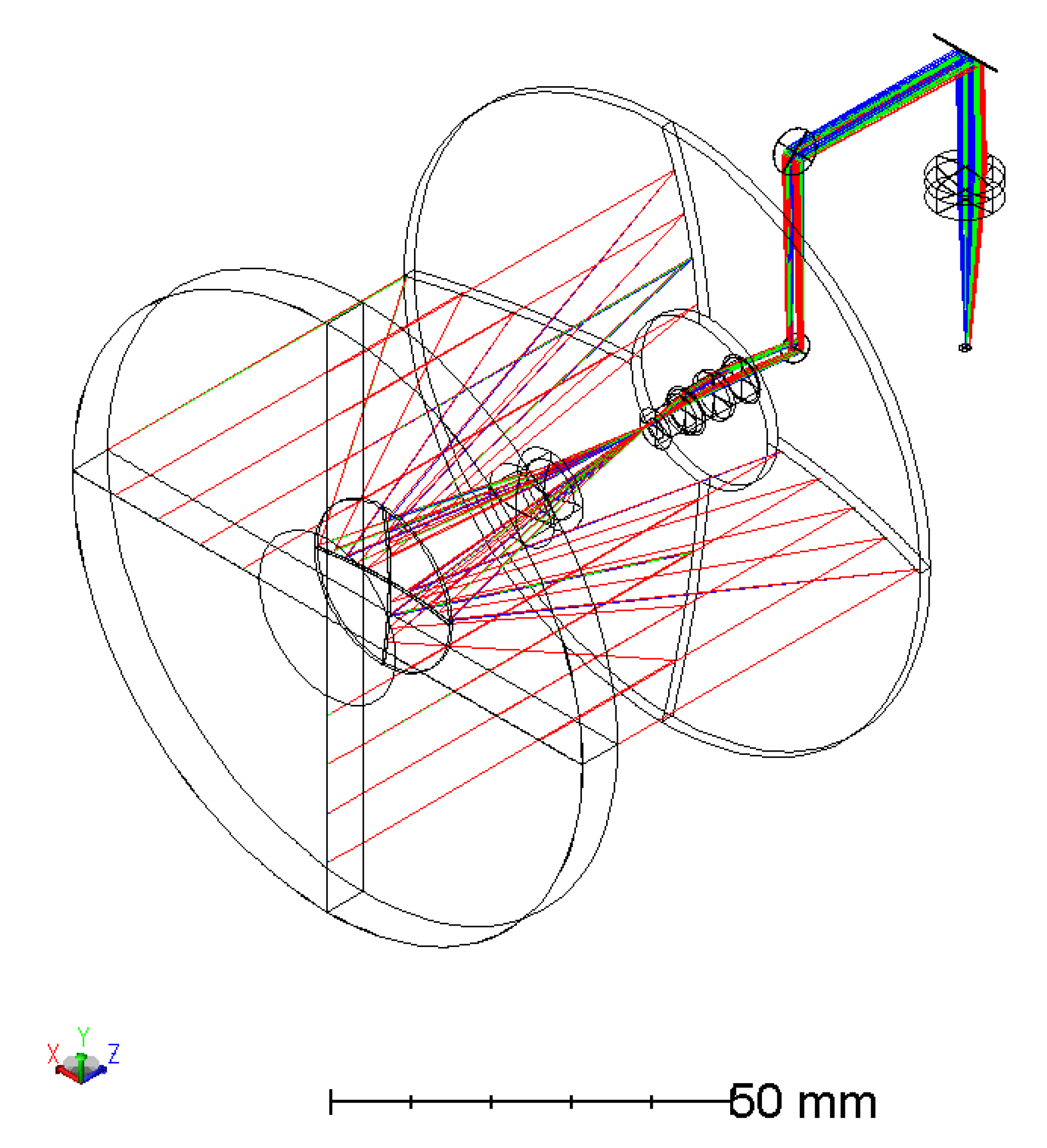
Transmission optics: The transmission optics is specified as a 30× telescope of 90-mm diameter (
Figure 5). The exit pupil position, where the MM will be placed (back-focus position), and the size of the rear element should be compatible with the APT system geometry. The telescope should be athermal for the range of temperatures of operation, nominally
C to +
C, and should be achromatic over the wavelength range 800 nm to 850 nm. The optics should be polarisation insensitive along the (transmissive) quantum signal beam path. A maximum volume of 2U is specified for the transmission optics; this should be achievable with a reflective or catadioptric design, and its mass should be below 2kg.
In summary, a 6U CubeSat is proposed for the QUARC mission, which comprises approximately 2U of volume for the APT and source, 2U of volume for the telescope system and 2U of volume for the supporting platform systems. The supporting systems not only must carry out housekeeping operations such as power management, command and data handling, and telecommunications to traditional ground stations but also must take care of advanced functions such as coarse pointing via an ADCS and orbit station-keeping using a propulsion system. Orbit station keeping is required to maintain precise Earth and Sun synchronisms, without which the repeat ground track characteristics would quickly be lost, sacrificing targeted coverage over the chosen region. This will be further discussed in
Section 4.
3. Channel Analysis
Losses as well as spurious counts are detrimental for the final secret key rate as it makes the quantum state less distinguishable [
11,
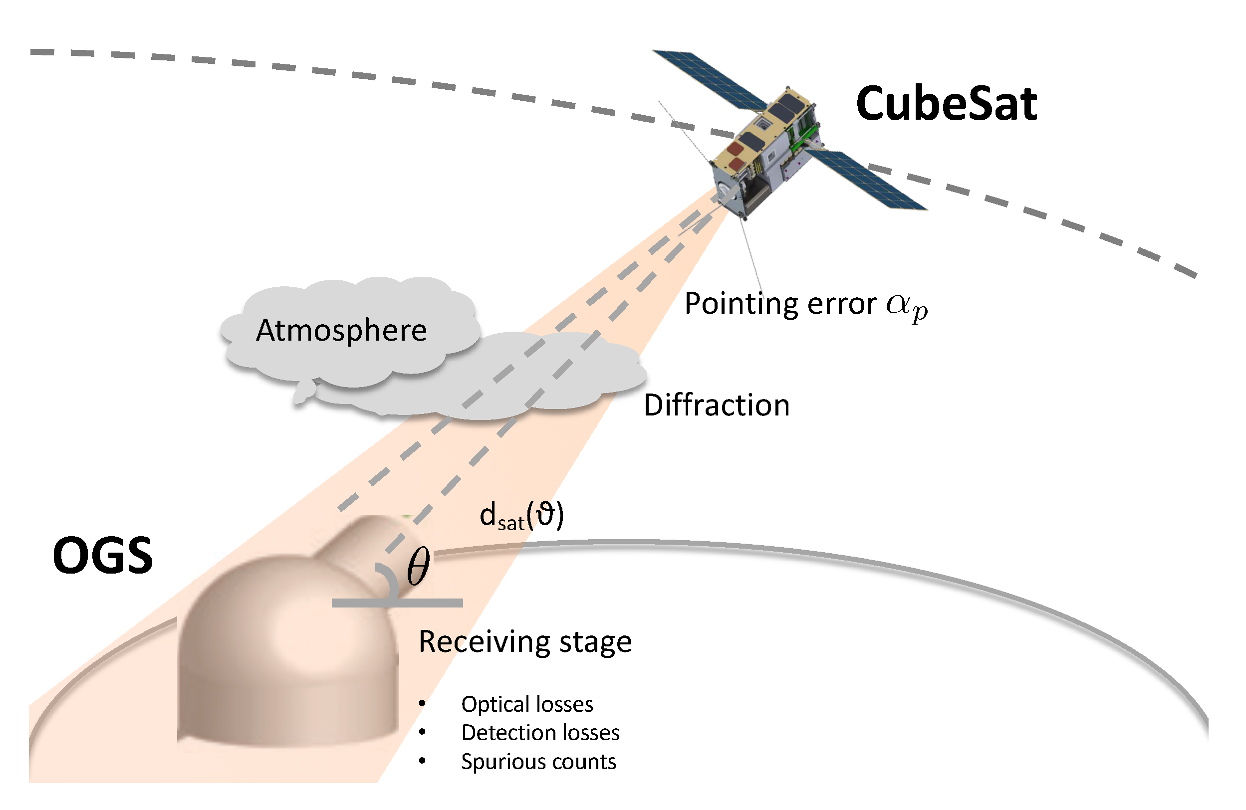
60]. In this section, we are going to model the channel between the satellite and the OGS and to review the source of losses and background counts. The physical scenario is summarized in
Figure 6.
3.1. Channel Losses
Diffraction: Losses due to diffraction of the transmitted beam over the distance between satellite and OGS are by far the most important losses. The distance depends on the orbital altitude and on the elevation of the satellite, as seen by the OGS. In this proposed mission, we consider a circular orbit with an altitude of 574 km; the distance between the satellite and the OGS will thus range between 574 km—at Zenith—and approximately 1500 km at an elevation of 15 above the horizon.
The full divergence of the beam is
rad (first minima of the far-field airy distribution assuming a flat-top transmission intensity). If we denote the transmitter (receiver) aperture with
(
) and with
—the range between the satellite and the OGS for a certain elevation
—diffraction loss for a beam propagating in the vacuum is given by the following [
61]:
The latter expression implies a quadratic increase of losses with the distance travelled by the optical beam. We assume a transmitter aperture of 90 mm and a receiver aperture of 700 mm. The transmitter aperture value is the maximum that can be accommodated in a 6U satellite without the use of deployable optics. The receiver aperture is comparable to the 600-mm primary mirror of the transportable optical ground station developed by DLR for downlink optical communication [
62]. Furthermore, commercial, off-the-shelf (COTS) 700-mm telescope systems are available from companies such as PlaneWave [
63] that are purposed for satellite laser communications [
64].
Atmospheric Losses: The atmospheric losses are due to scattering and absorption from the atmospheric constituents, and they are relevant only within 20 km from the ground, above which the atmosphere is extremely rarefied. Atmospheric losses depend on the incident wavelength and, being linked to the path travelled by light, on the elevation angle. This behaviour is captured by the following Equation [
65]:
linking atmospheric losses and elevation angle.
is the vertical transmissivity, which is dependent on the signal wavelength and, in the case of 808 nm, is 0.77. The atmospheric transmissivity decreases to 0.5 at 15
elevation [
66].
Transmission Pointing Error. As pointed out in
Section 2, an increase in pointing error,
, increases losses. For a certain beam divergence,
, the point error relates to losses via the following relation [
50,
65]:
In the current simulation, we assume a pointing error of 1 rad, leading to a transmissivity of approximately 0.9. Field trial results indicate that this target precision should be possible with further development of our system. It is worth noting that relaxing the pointing requirement to 5 rad would induce 7 dB extra loss.
Turbulence. Turbulence is a major issue for all free-space optical communication as it causes time and spatially varying regions of refractive index deviations [
56]. Light beams can experience deflection (when the characteristic size of the turbulence is large compared with the beam) and wavefront aberrations (when the converse is true) passing through these regions. The DL configuration experiences comparatively little loss due to turbulence compared with the UL configuration, the so-called shower curtain effect. This is because the DL beam experiences turbulence-induced deflection and aberrations only over the last 20 km of its path when its size is much larger than the turbulent eddies; its centroid is thus not going to be displaced significantly. UL beams suffer 10–20 dB more turbulence-induced loss by comparison, as any deflections induced at the start of their path cause large errors at the position of the satellite [
50,
51,
56].
Optics Efficiency. Absorption for the transmitting optics can be pre-compensated choosing a suitable laser intensity as we assume that the satellite is not under the control of a third malicious party. As for the receiving optics, in a standard BB84 setting, a received photon will traverse two beamsplitter; we assume a 50 % transmissivity per optical element.
Detection Efficiency. We assume the use of conventional Si-avalanche photo-diode (APDs) with standard
qe; this value is consistent with that of COTS devices, and this could be improved by using superconducting nanowire single photon detector (SNSPDs) but at greater expense and SWaP, albeit on the ground [
67].
In
Figure 7, the total channel loss against the elevation angle is plotted beginning at
. Total losses range from approximately 47 dB to 35 dB.
3.2. Spurious Counts
Spurious counts are due to electronic noise (dark counts), stray light coming either from the sky or from the environment surrounding the OGS, and polarisation basis errors. The former two sources can be reduced by time filtering the detection counts to narrow coincidence windows around the expected time of arrival of the signal pulses. Assuming a 1-ns gating window and a repetition rate of 100 MHz, we have a 1/10 suppression factor for dark counts.
Detector dark counts: The dark count rate (DCR) of a Si-APDs detector is estimated to be 50 counts per second. This can be improved by using SNSPDs.
Stray light: The stray light contribution to spurious events can also be mitigated by passive spectral filtering; a 1-nm filter (commercially available) effectively eliminates stray light in a rural setting, though it is not as effective in urban areas. Narrower, 0.05-nm filters are also feasible and can in principle enable daylight operation [
44]. The Doppler shift of a satellite in LEO is of the order of 0.02 nm; hence, narrower filters would not be suitable unless they could be spectrally tuned during the pass to follow the Doppler shift.
Assuming only nighttime operations and a moonless sky, we have a background count rate on the order of
counts per second [
68]. This may increase by an order of magnitude in the case where a full moon is in the FoV of the OGS.
Polarisation Basis Error: the transmitted and received polarisation bases may be misaligned, leading to detected counts in the wrong channel. We assume a misalignment of .
4. Mission Design
A satellite constellation is proposed, which offers QKD communication through regular, time-critical passes over locations of interest: in this case, the UK. In order to ensure regular coverage without the need for excessive numbers of spacecraft, a Sun and Earth synchronous orbit is proposed. This type of orbit benefits from both consistent illumination conditions over the long term from its Sun synchronism and repeat ground-track properties from its Earth synchronism. A propulsion orbit station-keeping system is required to ensure that such an orbit will be maintained for the duration of a mission. In addition, since a consistent satellite altitude is preferred over the course of the mission, a circular orbit is proposed. Satisfying all of these conditions limits the orbital combinations of altitude and inclination, and for the purposes of the QUARC mission, a repeat ground track after 1 day and 15 orbits is selected. This is achieved with an orbit altitude of 574 km and an orbit inclination of 97.68.
Constellation Topology. The number and orbital positioning of spacecraft for this mission dictates the level of coverage, which impacts the revisit rate to gateways and thus the communication capacity (ability to transfer data). For example, a single spacecraft would be capable of passing over the UK at most three times per night, with varying levels of elevation above the horizon depending on gateway location. This would not, however, directly translate into multiple key transfer opportunities per night for each gateway due to the fact that communication can only take place between a single satellite–gateway pair at any one time. Therefore, a greater number of spacecrafts would be required to ensure coverage of a greater number of stations, with multiple visits per night. Furthermore, populating multiple orbit planes would enable a distributed revisit schedule over some required period.
In order to obtain regular coverage over the full nighttime period, a constellation of 15 satellites in five orbit planes is proposed and evaluated (
Figure 8).
The satellites are separated in-plane (difference in true anomaly, TA) by 25
such that passes overhead of a particular ground location occur at intervals of 6 minutes 40 seconds for each of the three-satellite clusters. The orbit planes are separated (difference in Right Ascension of Ascending Node, RAAN) by 30
, which ensures that direct overhead passes occur at 2 hour intervals. Passes with a lower elevation above the horizon, relative to each of the gateways, occur during the orbits preceding and following the overhead pass such that a total of 45 passes are experienced per night from this constellation. A summary of the orbit parameters is shown in
Table 1.
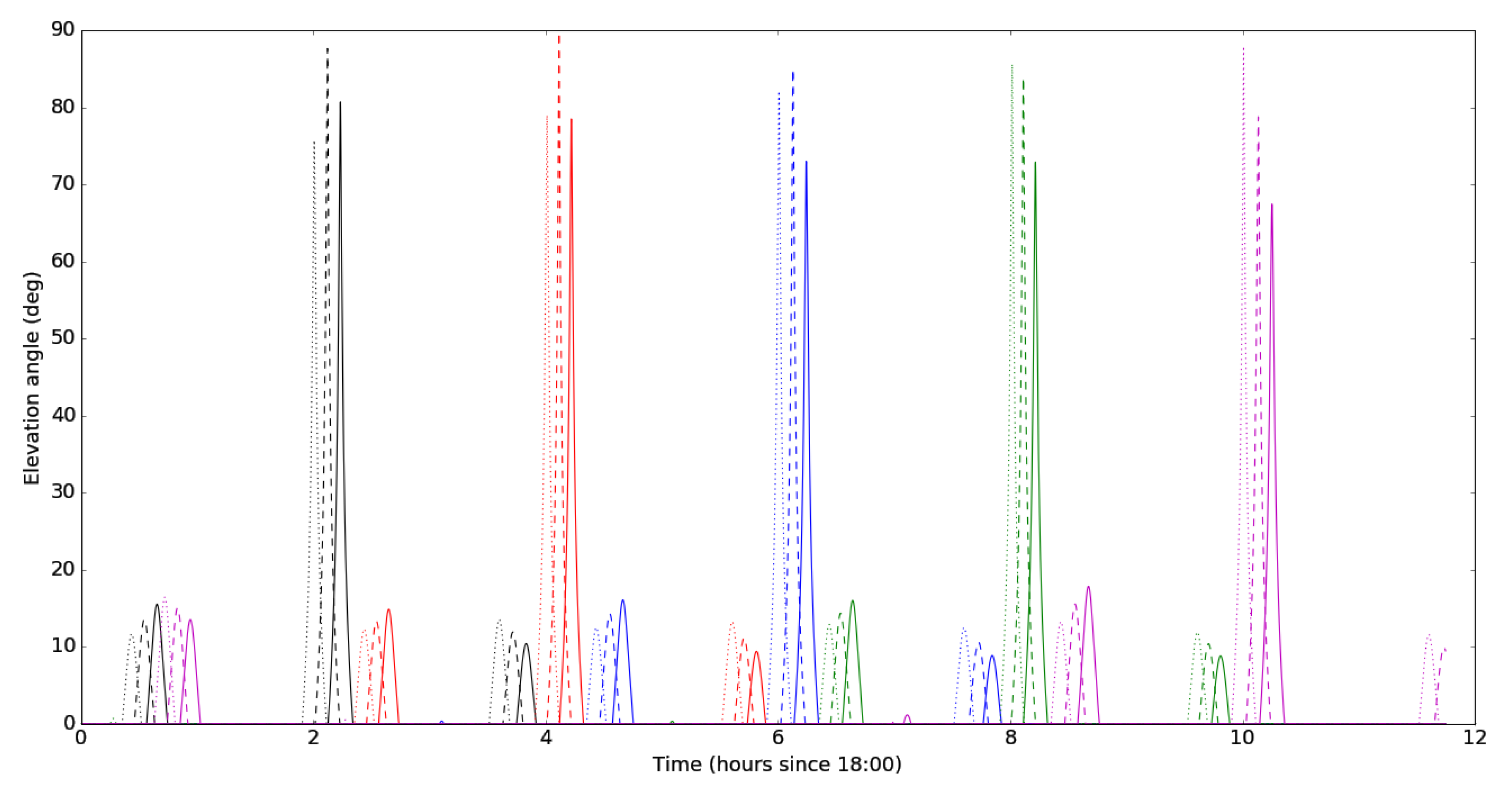
The overhead passes are designed to occur at a local time of approximately 20:00 hrs, 22:00 hrs, 00:00 hrs, 02:00 hrs and 04:00 hrs (
Figure 8). E.g., the first satellite to pass directly over the UK each night (in the eastern-most plane) should do so early on in the night, while the final satellite to pass directly over the UK (in the western-most plane) should do so in the early hours of the morning. A plot of the elevation angle relative to a point approximately in the centre of the UK (latitude 51.507
, longitude −0.128
) over time is presented in
Figure 9, in which the data for each satellite triplet are represented by a different colour and the data for each satellite within each triplet are represented with either a dotted line (first to pass), a dashed line (second) or a continuous line (last in the triplet).
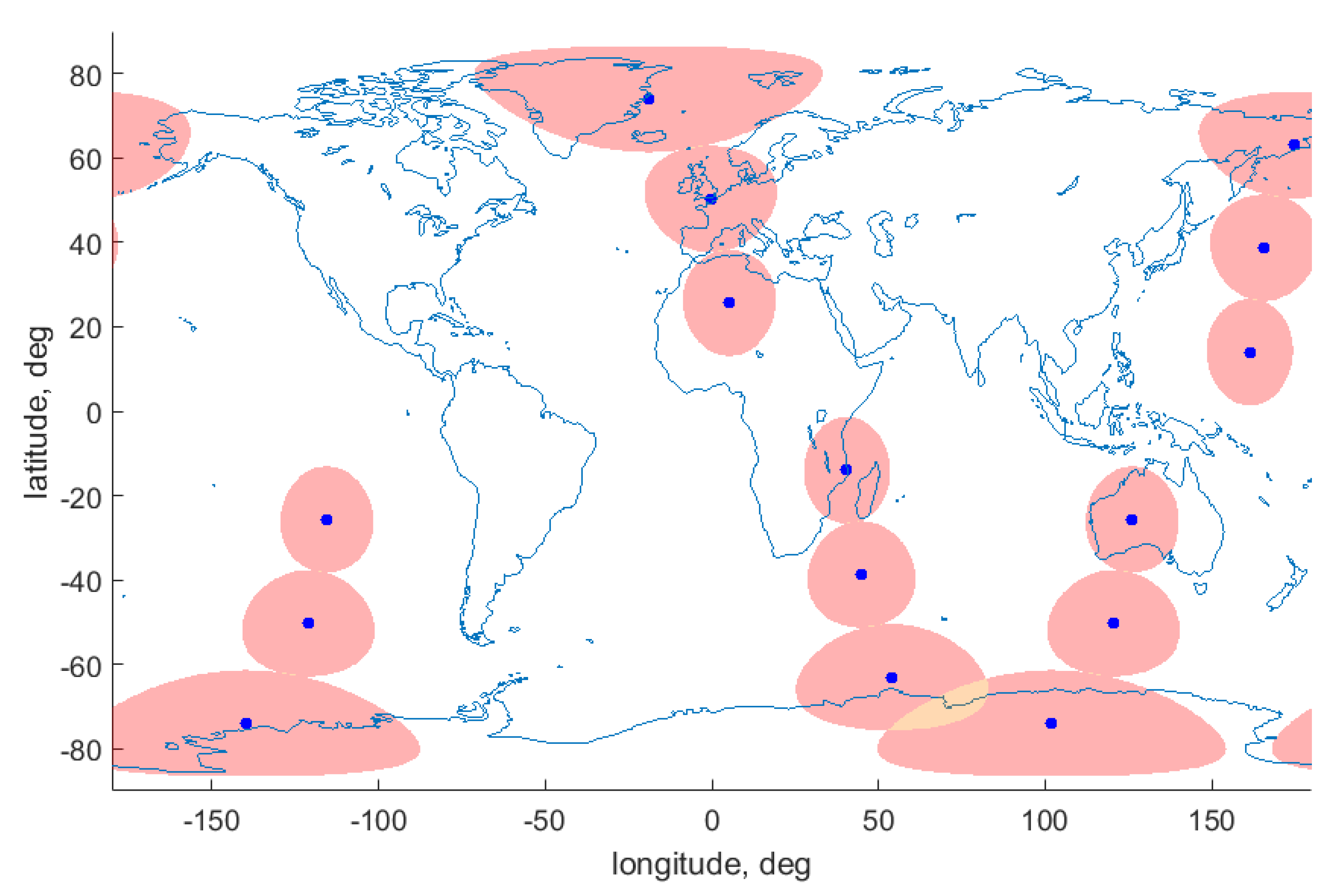
Approximately 12 hours after the nighttime ascending passes, there will be a set of associated descending daytime passes, which, while of limited value from a QKD perspective, could offer opportunities for data transfer over traditional (RF) methods of communication. The subsatellite point locations and footprint in which each satellite would be visible is shown in
Figure 10 at a time of 00:06:40 hrs.
5. QKD System Performance
True single-photon sources are not a mature technology, yet [
69,
70], the vast majority of QKD implementations use faint laser pulses. The Poissonian photon statistics of coherent pulse makes them vulnerable to the so-called photon-number-splitting attack. This is where an eavesdropper performs a weak measurement, selectively blocks all pulses containing a single photon and only resends those containing more than one photon, thus allowing them to have a perfect copy of the exchanged key. This attack can be counteracted by using decoy state methods [
71,
72], where pulses with different average photon numbers are randomly sent and are used to estimate channel transmissivity and to detect eavesdropper activities. The asymptotic key rate and the quantum bit error rate (QBER) are given by following expressions respectively:
where
is the repetition rate (100 MHz),
is the basis reconciliation factor,
is the error correction efficiency,
is the binary entropy,
is the signal gain (the ratio between the number of events detected by Bob and the number of signals emitted by Alice),
and
are the estimated gain and the error rate for single photon pulses respectively, and
is the loss as a function of the elevation. In what follows, we are going to consider the following parameters:
for the probability of a dark count,
for the error linked to the stability of the optical system and
for the detection efficiency. We also consider signal state and decoy state mean photon numbers per pulse of 0.5 and 0.1, respectively. We have chosen fixed values for the intensities; the optimal values depends on the channel conditions but might be hard to compute on the fly. We will leave such optimization as well as the analysis of statistical fluctuation on the key rate for futures works.
QKD requires LoS with a ground station in order to carry out communications; the rate of secret key rate is dependent on the range between the two terminals. As such, in order to maximise key exchange, it is desirable to communicate with ground stations that are directly under the flight path of the satellite: the Zenith condition. This is not always possible due to the nature of orbital mechanics, such that an understanding between the key rate and satellite elevation above the ground terminal’s horizon is useful in order to improve the amount of exchanged keys. In a perfect visibility scenario, i.e., no disturbances from the cloud, the following key rates are possible at a wavelength of 808 nm as a function of elevation angle (
Figure 11).
Ground terminal passes reach various maximum elevations throughout a mission such that the actual number of secure keys exchanged will vary. These are calculated numerically during the simulation, and the key rate (
) in bits per second (
Figure 10) can be approximated as a 3rd-order polynomial of the elevation angle (
), using the following equation:
In order to present a real case scenario estimation, we need to consider cloud cover [
73], which, if present along the LoS between the spacecraft and ground terminal, prevents any signal transfer.
In order to estimate the probability of LoS between the satellite and gateway, sunshine data is used as a proxy for cloud cover [
74]. The primary benefit of this, over direct cloud cover, is that it can be considered a more representative analogy of LoS due to the fact that it is also a measure of a space-borne signal arriving at a ground-based sensor. The data, obtained from the UK Met Office, provides daily averages for the number of sunshine hours at all locations across the UK at a resolution of 5 km × 5 km [
75]. This is provided as an average for each month of the year such that daily or even hourly insights are not obtained. This temporal resolution means that it is not possible to consider different cloud formation effects, e.g., a probability of 50% that the sun is shining does not differentiate between patchy cloud cover over the whole month, complete overcast for half the month and clear skies for half the month, or something in between. The practical implication of this is that these different scenarios will have a different impact on the qkd operations.
Based on an understanding of the day length at various points throughout the year, derived using sunrise and sunset times, it is possible to estimate the average cloud-cover fraction for a specific location. For example, if the time between sunrise and sunset is 12 hours for a certain location in a certain month and the average daily sunshine hours is 6, it can be inferred that there is, on average, 50% cloud cover at that location. It is assumed that this cloud cover approximation remains the same during nighttime hours.
In order to represent the effect of cloud cover on the mission performance, the transfer of keys is modelled such that the key rate is reduced by a fraction equal to the expected level of cloud cover, i.e., a cloud cover will lead to a decrease in the volume of key exchanged. This can be considered a best-case scenario in terms of performance, given that a patchy cloud coverage would impact the performance more than a simple block cloud-coverage scenario.
The time of sunrise and sunset varies significantly throughout the year, and the variation is latitude dependent. The northerly gateways will receive longer dark periods during the winter months and shorter dark periods during the summer months compared to their southerly counterparts. It should be noted that, for the purposes of QKD transmission in this work, sufficient “darkness” is considered to be the time between civil dusk and civil dawn, i.e., when the sun is below the local horizon (elevation angle of less than 0).
6. Mission Analysis and Results
Analysis of the QUARC mission has been carried out in order to understand the level of performance that could be achieved by a satellite constellation providing QKD services to a UK-wide network of ground-based gateways. Performance, in this case, is defined as the volume of secure key data that could be transferred between the satellites and gateways per night. Figures of merit have been derived that offer insights into the performance for both an individual gateway and a network of gateways. Specific results are provided for the hypothetical gateway network, defined in
Section 1, but the methods introduced here could be applied to understand performance of a different set of gateways.
The primary performance metric being investigated is the amount of secure key data that can be exchanged between satellites and gateways, as a function of the gateway location and the number of satellites in the constellation. Assuming that more key information is generally better, we would naturally aim for this; however good performance is more complex than this, depending on the objectives. For example, it might be the case where the maximum number of exchanged keys is achieved when a large number of keys are exchanged between a small number of ground terminals and satellites; however, a more uniform spread of keys might be desirable across the network. Alternatively, should specific terminals have higher priority than others, it may be preferable for those terminals to receive more keys. This level of detail is application specific, such that the analysis here is kept intentionally generic. A uniform priority is assumed therefore, such that resource is distributed to gateways according to their relative availability.
Performance will be captured for each gateway (
j) as a measure of the volume of shared key information per night for each month of the year (
k). This is calculated as part of the simulation defined in the following section and is defined as follows:
where
is the average volume of secure key data transferred per satellite per night to gateway
j via a constellation of
n satellites. This is based on the assumption that communication can only be between a single satellite–gateway pair (i.e., the satellite cannot transmit data to more than one gateway at any one time) and assumes that the influence of each satellite in the network on each of the gateways is similar. This latter assumption is considered acceptable given the close proximity of the gateways relative to the field of view from the satellites.
Using the above figure of merit means that, for this particular infrastructure, it is possible to understand the volume of key data that can be exchanged with gateways at different locations across the UK for different months through the year as a function of the number of satellites in the constellation. Indeed, a natural limitation exists due to the fact that there are only so many dark hours during the night, i.e., the maximum number of keys would be reached should there always be a satellite available for key transfer.
As well as the number of satellites in the constellation (
n), the number of gateways being targeted (
m) has a significant impact on the performance for each gateway independently. To generalise the problem, the relative transfer volume (maximum theoretical volume of key data per night) to each gateway in the network must be considered, such that the respective impact is proportional to this value. The secure key volume (
V) delivered to gateway
j during month
k can thus be estimated as follows:
where
is the volume of data that could be transferred to gateway
l during month
k per satellite in the constellation. For example, consider a network of three gateways to which a key transfer capacity is considered as the potential to transfer data. For example, for a satellite that experienced two opportunities to transfer data to a gateway per day over which 20 MB and 10 MB could be transferred, respectively, the daily transfer capacity between these two nodes would be 30 MB. Ten, 5 and 0 per satellite per night can be attributed, respectively. Given a constellation of three satellites, gateway 1 would expect to receive 13.3 units per night, gateway 2 would expect to receive 3.3 units and gateway 3 would receive none. Effectively, this assumes that the available satellite resource is distributed to the gateways in a manner that is proportional to their respective potential transfer volume.
6.1. Model definition
Analysis of the QUARC mission performance (secure key transfer capacity) has been achieved through execution of a high-level numerical simulation model in combination with illumination and cloud-cover modelling (
Figure 12). The simulation model considers the relative position of each satellite–gateway pair and outputs the elevation angle above the horizon for each step in the simulation. The simulation has a time-step duration of 10 seconds and represents 12 hours of real-time operations (between 18:00 hrs and 06:00 hrs).
The simulation results are combined with a sunrise–sunset model for the 15th day of each month of the year to establish the rate of key transfer during each gateway pass and the nominal (clear sky) satellite–gateway secure key volume transfer capacity. This nominal key volume capacity for each monthly 12-hour period is scaled according to the expected level of cloud cover (e.g., 50% cloud cover would scale the key volume for that period by a factor of 0.5).
The result of this analysis process is an expected secure key volume per satellite per gateway location for each month throughout the year and is illustrated in
Figure 13.
6.2. Single Gateway Results
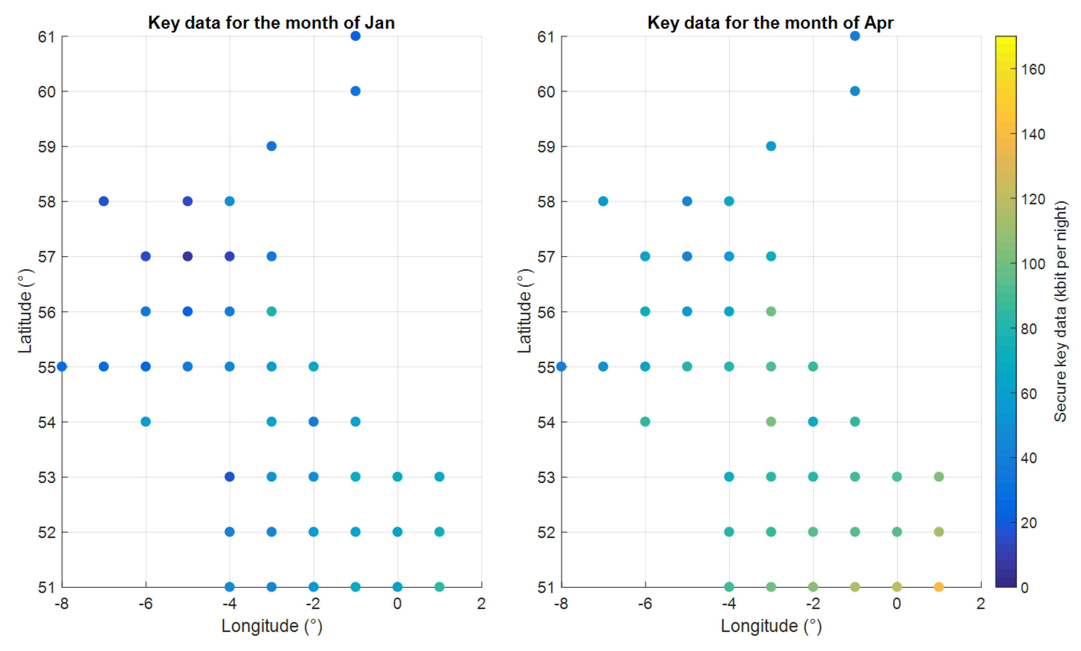
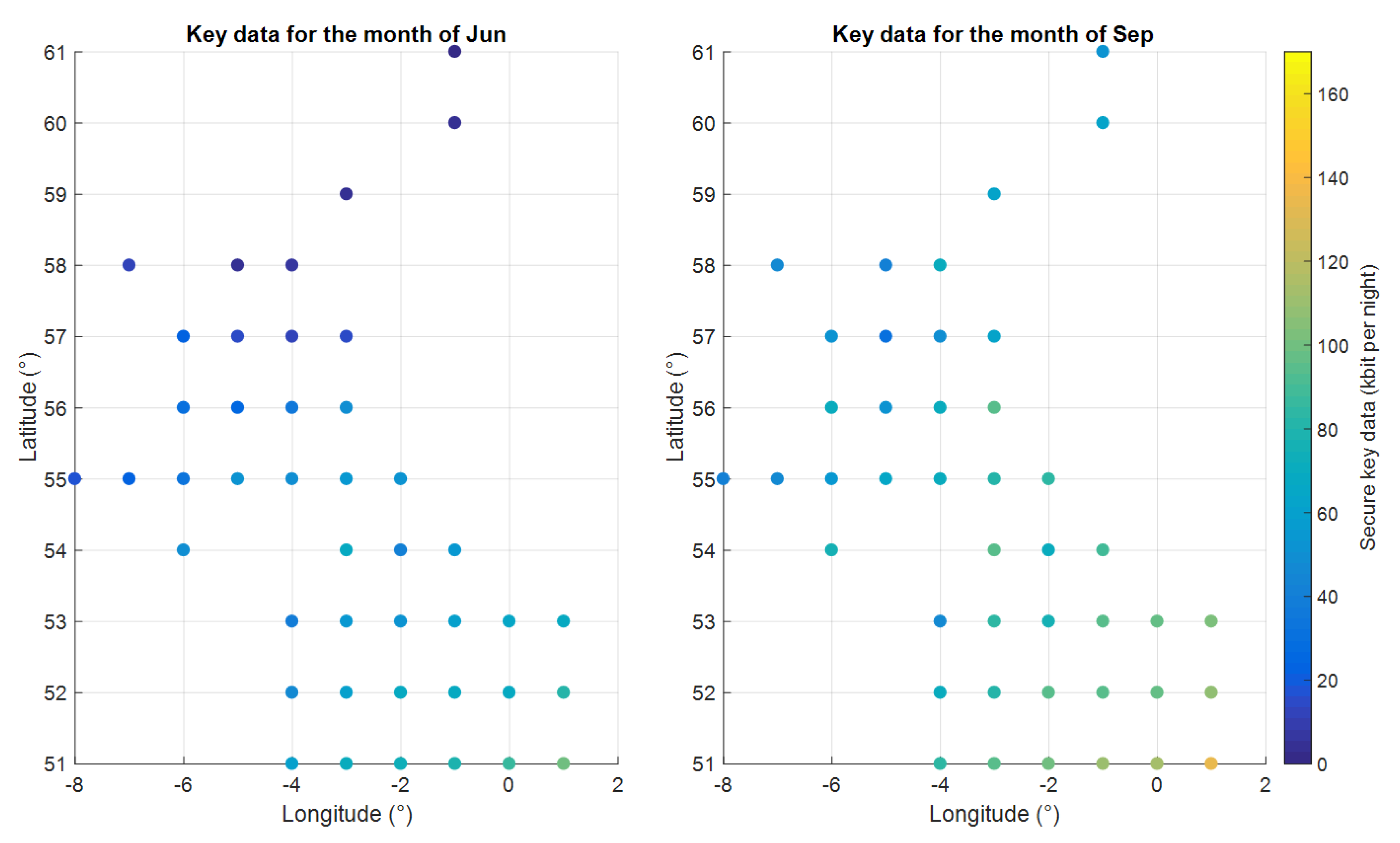
The results shown in
Figure 13 and
Figure 14 illustrate the volume of secure key transfer to each gateway per night per satellite in the constellation for the months of January, April, June and September. It is important to note that these results show a hypothetical scenario for each gateway independent of all the others, i.e., assuming no other gateway is demanding satellite resource. This enables an insight into each gateway’s relative capacity.
From the above results, the variation in performance between different locations over the year is not straight forward. It is a complex coupling of dark sky duration, expected cloud coverage and satellite visibility. In general, the volume of secure key data transfer is greater during spring and autumn than in summer and winter. This can be attributed to significantly longer days in the summer months and significantly greater cloud coverage during winter months. Some locations exhibit uncharacteristically good performance compared to their surrounding regions, such as the east coast of Scotland (Lat 56, Lon −3) during the month of September.
6.3. Scaling for a Specific Gateway Topology
In the case where all 43 hypothetical gateways are demanding of resources from the 15 satellites, the resources are modelled as being shared according to each gateway’s data-transfer capacity. Results are presented, again for January and April (
Figure 15) and for June and September (
Figure 16), showing the volume of secure key data that would be expected at each of the gateway locations per satellite in the constellation. Of course, in reality, operational requirements might demand a different distribution of resources, such that this approach can be seen as one particular use case.
While similar trends are seen in the results shown in the previous section, the variability in the transfer capacity is exaggerated due to the provision of data-transfer resources relative to communication capacity. This should be expected since more resources are applied to the gateways with greater transfer capacity in order to maximise the data transfer during times of high availability.
6.4. Time scale and budget considerations
COTS 700-mm aperture telescope systems for satellite optical communications are available for USD 200K [
63,
64]. With additional costs for the quantum receiver hardware and housing structure, a single OGS should cost less than USD 500K. The cost for the QKD ground segment could be considerably reduced by colocating SatQKD and conventional satellite laser communication infrastructure, i.e., utilising the same telescope for both operations. The main areas of payload development are source miniaturisation, ruggedization and security hardening; timing and synchronisation systems; thermal design and analysis; design and manufacture of transmission telescope optics; and space-qualified software. A reasonable time scale for the development of this is 24 months given sufficient resources, and we envisage a recurring cost per CubeSat of around USD 500K (USD 300K platform, USD 100K optics and USD 100K other payload systems).
Launch costs are variable depending on whether a suitable rideshare opportunity into the desired orbits is available. Conservatively, we will assume a dedicated launch on a small rocket such as Rocket Lab’s Electron which can put 220 kg into Sun synchronous orbit for USD5M [
76]. The cost to deploy the constellation can thus be conservatively evaluated at USD25M assuming five separate launches, placing three 6U CubeSats into each orbital plane. Considering the capacity of the electron launcher (220 kg) and taking into account deployment container mass, each launch could place up to 15 6U CubeSats per orbital plane, which would greatly increase constellation capacity and would provide in-orbit redundancy. Alternatively plane-change manoeuvres could be achieved through raising or lowering the orbit altitude and by relying on a shift in right ascension of the ascending node through Earth’s oblateness effects. While this approach is cost effective regarding launch, it requires time and propellant and adds an additional risk to the mission success. Once development is concluded, the deployment could be achieved in about 12 months (6 months assembly, integration and test of the payload/satellite, together with 6 months for integration with the launch vehicle and launch operations). These time and budget estimates indicate that a CubeSat constellation for QKD is in reach and can be developed within the framework of currently available technology.
The above results provide insights into the amount of secure key data that can be transferred to a UK-based ground network via a 15-platform CubeSat constellation. Indeed, operational and geographical constraints will play a significant part in real-world performance, which should be considered carefully in future studies. This can only be evaluated fully on a case-by-case basis, but the general approach and figures of merit defined in this work should offer a good starting point.
7. Conclusions
In this work, we have analysed the QUARC mission concept for a nanosatellite constellation to provide the UK with a satellite-based QKD capability. Due to the relatively low cost of CubeSats compared to traditional, large satellite platforms, deploying a large number of platforms may offer greater coverage which would mitigate some of the risk associated with performance limitations linked to cloud cover. Satellite constellations will also offer greater flexibility than a single platform when it is required to accommodate the communication demand of the underlying gateway network. Satellite-based QKD for securing critical infrastructure is of current interest with the launch of the EC-ESA Quantum Communication Infrastructure (QCI) initiative [
77] that will require a space segment for continental-scale secure networks [
78]. The UK is also pursuing CubeSat-based efforts to accelerate SatQKD as part of the National Quantum Technology Programme [
37], and QUARC provides preliminary mission and performance analyses that will inform future developments.
An example mission topology has been presented, which includes a ground network of 43 gateways (to represent a large UK-infrastructure project) and a 15-satellite constellation. The satellites are placed into 574-km circular orbits, which are both Sun and Earth synchronous in order to ensure good coverage over the UK and consistent passes at useful times overnight.
A QKD payload and its performance have been modelled and tested to provide input for the secret key rate as a function of elevation. We have chosen trusted node QKD in order to reflect near-term realizability. Conservatively, we have assumed nighttime operation only. Operation during twilight hours may be possible with a reduction in key rate, thus extending the times at which key distribution could be performed.
In order to evaluate the secret key volume, we have developed a comprehensive channel simulation incorporating orbital propagation for the satellite constellation, twilight duration, losses, spurious event source as well as historical weather data. Our results show that a CubeSat constellation has the potential to deliver a small but reliable amount of secret key that could be used in scenarios where highly secure communication is required, such as critical infrastructure management. Performance at specific gateway locations is shown to be highly dependent on geographical position and seasonal conditions. It is found that, in general, southern regions offer a more consistent long-term average rate of key transfer but with isolated regions further north benefiting from long overnight dark periods and minimal cloud cover during some winter months. The mission analysis results presented offer indicative levels of performance for gateways distributed across the UK; however, it is recommended that mission-specific analysis be carried out for different topologies [
41].
Furthermore, our finding suggests that payloads optimised for operation with high background levels of light may be beneficial to extend coverage at high latitudes during the summer months, e.g., 1550-nm operation and aggressive temporal, spatial and spectral filtering. A shift toward 1550 nm would be also desirable in order to implement intersatellite links [
42,
43,
44,
45]. This may however compromise peak key distribution rates; hence, further studies will be needed to perform optimisation across payload and mission parameters coupled with a detailed key-demand and network-usage model including key buffering and refresh rates.

 ,
, 


