Novel Schemes for Compact FELs in the THz Region


ENEA, Fusion Physics Division, C.R. Frascati, via E. Fermi 45, I-00044 Frascati (Roma), Italy
*
Author to whom correspondence should be addressed.
Condens. Matter 2019, 4(4), 90; https://0-doi-org.brum.beds.ac.uk/10.3390/condmat4040090
Submission received: 23 October 2019
/
Revised: 8 November 2019
/
Accepted: 15 November 2019
/
Published: 19 November 2019
(This article belongs to the Special Issue THz: Research Frontiers for New Sources, Imaging and Other Advanced Technologies)
Abstract
:The rapid advance of terahertz technologies in terms of radiation generators, systems, and scientific or industrial applications has put a particular focus on compact sources with challenging performances in terms of generated power (peak and/or average), radiation time structure, and frequency band tunability. Free electron laser (FEL)-based sources are probably the best candidates to express such a versatility; there are a number of schemes that have been investigated over the years to generate coherent radiation from free electrons in the mm-wave and terahertz regions of the spectrum, covering a wide frequency range from approximately 100 GHz to 10 THz. This paper proposes novel schemes for exploring the limits in the performance of radio frequency-driven free-electron devices in terms of ultrashort pulse duration, wide bandwidth operation, and energy recovery for near continuous wave (CW) operation. The aim of the present work is to demonstrate the feasibility of an FEL achieving performance comparable to a conventional photoconductive THz source, which is commonly used for time-domain spectroscopy (TDS), in terms of bandwidth and pulse duration. We will also demonstrate that a THz FEL could be very powerful and flexible in terms of tailoring its spectral features.
1. Introduction
Time domain-based terahertz (THz) sources have gained more and more attention during the past 15 or 20 years [1], and these systems are now commercially available, reliable, and easy to use. Such THz sources are mainly divided in two categories that are both characterized by broadband emission. The first is the Auston switch, which is named after the American researcher that initiated this research field [2]; the device is made up by a coplanar strip antenna deposited on a nonabsorbing photo-conducting substrate. The circuit, biased by an appropriate voltage, can be closed by a focalized powerful short infrared laser pulse on a gap of few microns. The transient current gives rise to a time-dependent electric field, and the consequent polarization vector follows the envelope of the laser pulse. The most important drawback of the Auston switch is its limited bandwidth and the frequency dispersion that results in a rapid lengthening of this pulse before the launching in the vacuum. The limit bandwidth for these devices is of the order of 1 THz. To overcome this limitation, a different approach has been developed. The idea is to use an electro-optic device realized with a nonabsorbing material [3]. The interaction mechanism is now a nonlinear second-order process: the rapidly oscillating electric field of the laser pulse excites in the medium a polarization vector which is proportional to the modulus of the electric field itself. This polarization vector is the source for a Hertzian vector potential that generates a radiation field. This is a rectification process because the rapid oscillation of the electric field of the laser pulse is averaged in the frequency domain and only the envelope of this pulse remains. Being the medium weakly absorbing, the polarization vector can be very fast in following the laser profile; this means that there are a few limits in the bandwidth of the THz pulse that can be generated with such devices. The main drawback is that, since this is a second-order process, the intensities of the THz radiation are reduced with respect to the Auston switch, but high intensities can be achieved by the more powerful short-pulse infrared laser source now available also commercially. A complementary and alternative approach, based on free electron devices, is discussed in the present paper.
2. The Free Electron Laser
In order to understand how a free electron laser can perform in a way similar to the time-domain THz sources, let us recall the main elements constituting a free electron laser (FEL). An FEL uses an electron beam generated by a particle accelerator that, due to the interaction with an external element, can emit radiation. To be more explicit, the electrons—which have several MeV of energy, properly aligned, and focused by steering coils and quadrupoles—are transported into the interaction region that in “conventional” FELs it constituted by a permanent magnet device called a magnetic undulator. Here, the electron kinetic energy is transformed in a radiation field by means of the synchrotron emission mechanisms, which can be considered a spontaneous emission process. With the addition of an optical cavity, the radiation is stored into a volume; therefore, the emission mechanism becomes stimulated by the simultaneous presence of the electrons, the magnetic field, and the stored radiation.
Relevant FEL relations are reported in Equation (1) indicating that the resonant wavelength is inversely proportional to the second power of the electron energy (expressed by the relativistic factor γ) and directly proportional to the undulator period λu and the magnetic field strength contained in the undulator parameter K. The efficiency is inversely proportional to the number of the undulator period N, and lastly, the gain is proportional to the electron beam current I and to the undulator length at the third power, but also inversely proportional to the electron energy at the fifth power. Moreover, the gain is proportional the function g(θ) of the detuning parameter θ = 2πN(ω − ω0)/ω0 (where ω0 is the spontaneously emitted frequency). It is important to point out that the synchrotron emission is not the exclusive emission mechanism for free electron devices, but is the one for which the interaction between the particle and field is more effective.
Therefore, it is possible to analyze the characteristics that an FEL should satisfy if designed to operate in the THz region. First of all, looking at the first part of Equation (1), the electron beam energy can be quite low, with respect to the visible and UV operations, and this allows the design of a compact FEL layout with small particle accelerators. A broadband emission that is typical of the conventional solid-state THz sources can be obtained by means of short interaction regions, which clearly add compactness to the overall device. This can be acceptable because the high gain is ensured by the low energy beam (see the third part of Equation (1)). To maintain the bandwidth as broad as possible, we must avoid the use of an optical cavity, which certainly reduces the frequency components, and obtain emission in a single electron passage. The lack of the optical cavity allows a straight-line e-beam propagation. In order to extract as much power as possible in a single-pass device, we have to work in the coherent spontaneous emission regime and super-radiant regime.
3. Coherence and Order in FELs
The previous section discussed the necessity of exploiting all the coherent mechanisms in order to avoid the use of an optical cavity for a THz FEL. The first degree of coherence is obtained when the electron bunch length is comparable to the wavelength of the radiation to be generated by the device. This mechanism was firstly proposed by Schwinger for the analysis of synchrotron radiation [4] and by V.L.Ginzburg to explain strong radiation emissions from astronomic objects [5]. From the classical electromagnetic theory, it can be demonstrated [6] that the emission into a solid angle dΩ in the frequency interval dω is
The function f(ω) in Equation (2) describes the coherence of the emitted radiation; its values range from 0 to 1. The limit f(ω) = 0 indicates an incoherent emission from the bunch that means that the power emitted by N particles is just the sum of N individual contributions. The upper limit f(ω) = 1 represents the total coherence, when the power emitted by N charged particles is given by N2 times the emission of the single particle. This result is fully equivalent to the emission of a single particle having a charge Q = Nq, because looking at Equation (2), power is proportional to Q2 = N2q2. In order to establish a suitable value for f(ω), we can observe from Equation (2) that coherent effects dominate when N<<N2f(ω), which implies f(ω)N>>1; for the typical case of an S-band radio-frequency (RF) accelerator, the number of electrons in a single bunch is about N~108; therefore, a suitable value range for the f(ω) function that guarantees high coherence in the emission starts from f(w)>>~10−4. This implies that the wavelength of the radiation generated should be longer than a fraction of the bunch length in order to have a coherent enhancement of the emission. Considering again an S-band accelerator, for which the bunch length is of the order of few millimeters, the result is that coherent emission dominates in the THz or at longer wavelengths.
A second degree of coherence can be exploited taking into account the relationship among all the electron bunches. In fact, an RF accelerator generates a train of pulses, and if the correlation among all the consecutive pulses is good, the radiation will be emitted at discrete frequencies that are harmonics of the RF [7]. This can be easily seen by making a Fourier expansion of the current, as shown in Equation (3)
where TRF is the RF period and l is the harmonic number. The spectral width of the single harmonic is related to the overall length of the bunch train, the so-called macropulse, as well as to the amplitude and phase stability of the bunches over the macropulse. Each harmonic component of the current acts as an isolated source that couples with the electric field of the radiation, which is expanded over the free space, or guiding structure modes Eλ [7]
where βg is the group velocity of the radiation pulse and Z0 is the vacuum impedance. The radiated power is calculated by means of the flux of the Poynting vector: .
A further degree of coherence can be added if we treat the bunch as a collection of N particles distributed in the longitudinal phase space [8]. Each electron carries its own energy γj and a proper position or phase ψj equal to the RF times the time tj along the bunch. Using the previous expression (4), the total radiated power can be calculated summing over the particle distribution
where Σ is the radiation mode size and k0,n is the transverse mode momentum. From Equation (5), we see quite explicitly that the presence of a phase factor gives rise to an interference mechanism; the contributions to the total power, given by the sum over all electrons, indicated by the index “j”, may result in constructive or destructive interference. To maximize the power extraction, by means of the Poynting theorem, it is possible to minimize the negative interference. This goal can be achieved when the phase term in Equation (5) is overall constant with respect to the single electron emission and will only depend by the harmonic number l influence. In conclusion, the ideal phase-matching distribution, which maximizes the power extraction by means of the minimization of the destructive interference, is obtained by putting the phase term equal to a constant φl that depends only by the harmonic number. The ideal distribution for the electrons, in the longitudinal phase space, is therefore as follows:
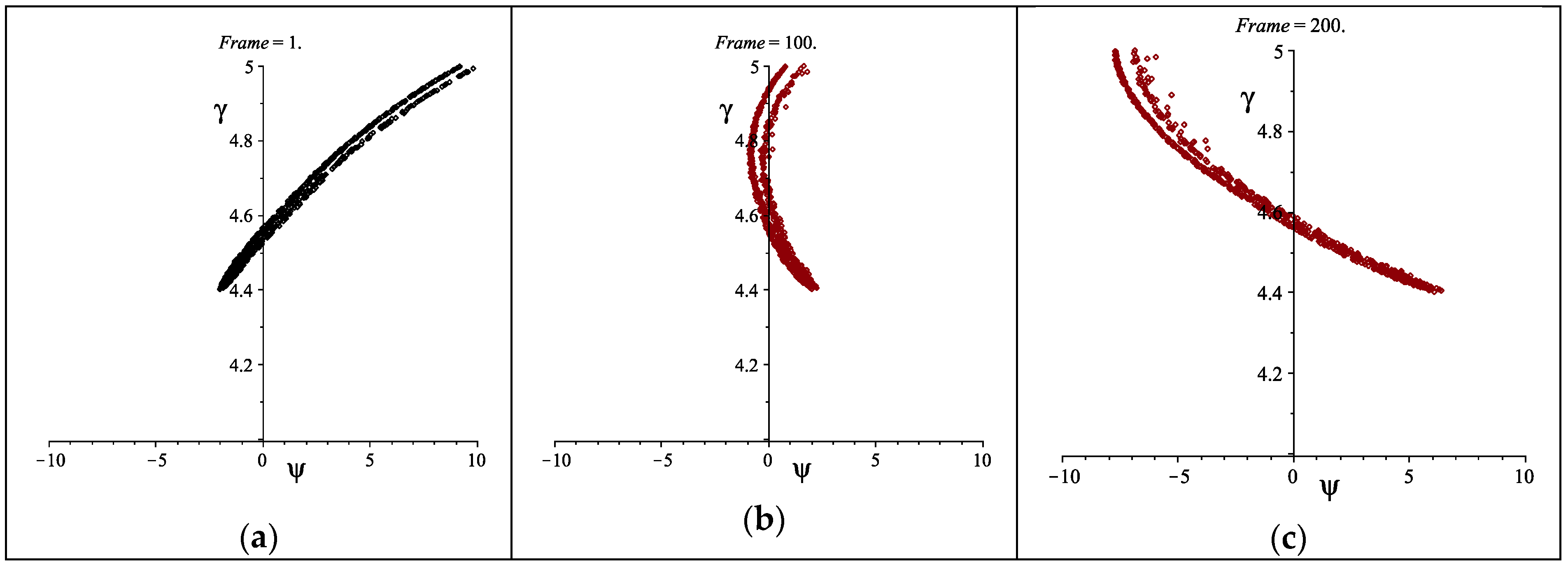
When the electrons in a bunch are distributed in the longitudinal phase space as in Equation (6), the radiation emission due to each particle is added in phase, as indicated by Equation (5), maximizing the power extraction during the interaction process. A different way to understand the meaning of the ideal energy-phase correlation curve is that, during the passage of the electrons inside the magnetic undulator, the combined ballistic and oscillating motion is such that the maximum bunching (and consequently, the maximum energy spread and the minimum temporal width) is obtained when the bunch reaches the center of the interaction region. So, the ideal phase-matching curve is the one for which the distribution realizes the best bunching at the undulator center [8] (see Figure 1).
In the ENEA Research Centre in Frascati, two FEL compact devices have been realized [9,10], in order to test the three described mechanisms for the generation of coherent radiation from free electrons. In particular, the FEL-CATS (Compact Advanced THz Source) [10] has been realized to test the energy-phase correlation mechanism for the emission of coherent radiation, up to saturation levels, without the use of any optical cavities. This FEL present an element called a phase-matching device (PMD) that is capable of manipulating the electron beam in the phase space. The PMD is an RF device located downstream of the Linac accelerator (2.3 MeV) in which the RF field amplitude and phase, relative to the Linac, can be controlled. This control allows the reference electron passing through the center of the PMD with a phase close to zero. The result is that the higher energy electrons, arriving first at the PMD, are decelerated, while the lower energy electrons are accelerated and emerge first from the PMD. This is exactly the required rotation of the electron distribution in the phase space. The FEL-CATS operates from 450 to 800 μm (corresponding to frequencies from 0.4 to 0.7 THz).
4. The Two-Frequency Cavity
In order to realize FEL sources generating radiation in the THz range with better performance than FEL-CATS, it is necessary to increase the electron energy (see Equation (1)) and to shorten the bunch duration (see Equation (2)). The PMD realized in ENEA for the FEL-CATS experiment is no longer adequate for such a task. A possible solution to this problem is the use of a two-frequency RF device [11,12]. In fact, such cavities offer appealing possibilities to control the bunch length of an electron beam generated by an RF accelerator. The use of a double-frequency cavity requires the second frequency to be a harmonic of the fundamental one, in order to be resonant. The electrons passing through the cavity will see a field that is the result of the sum of the two field components: the fundamental and its harmonic.
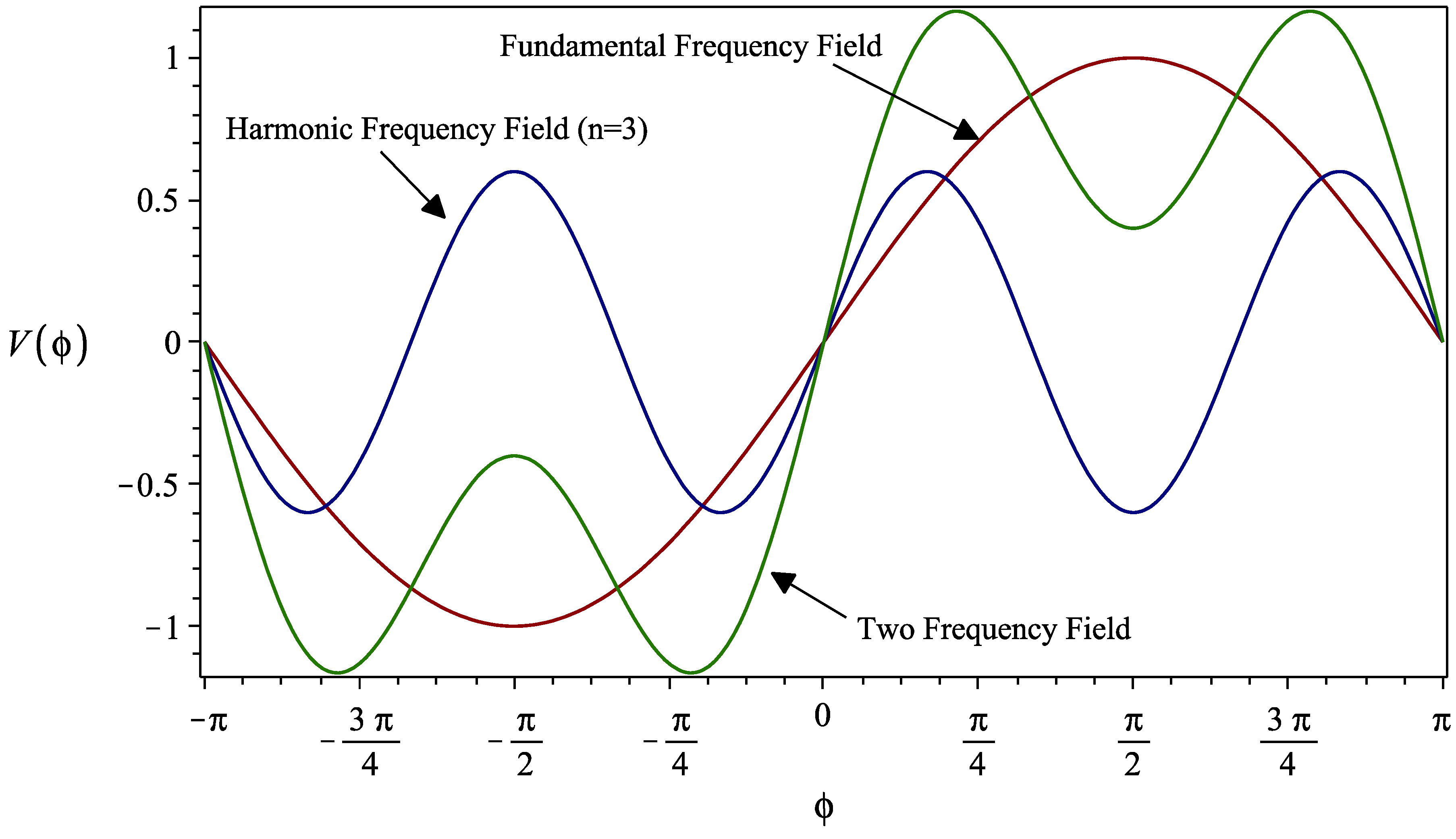
There are some design parameters that can be set, such as the harmonic number n and the relative amplitude ratio k that contributes to the bunch length, but the most relevant is the relative phase (φs-φn) between the fundamental and the harmonic. These parameters establish the slope of the total field in the cavity right where the electron bunch passes. Two different regimes can be in principle realized: one in which the particles gather with respect to the reference electron, and a second in which one can realize a pulse lengthening, whose spread can help dampen coherent instabilities that often cut down the bunch lifetime in recirculated accelerators. In Figure 2, the behavior of the total field in the two-frequency cavity is reported, as indicated by Equation (7), together with the fundamental frequency field and the harmonic frequency field.
The figure reports the ideal conditions to obtain the best bunching close to the reference electron, for a third harmonic field (n = 3) and a relative amplitude between the fundamental and harmonic of k = 0.6; the phases for the two fields are φs = 0 and φn = π. In this case, the total field results in a slope around the reference particle, whose steepness can be controlled by the amplitude of the third harmonic. This is the required solution for the bunching of the electrons up to the ideal phase-matching distribution reported in Equation (6).
From the calculation of the separatrix of the electron distribution in the longitudinal phase space, it can be demonstrated [11] that the bunch profile is given by the following expression.
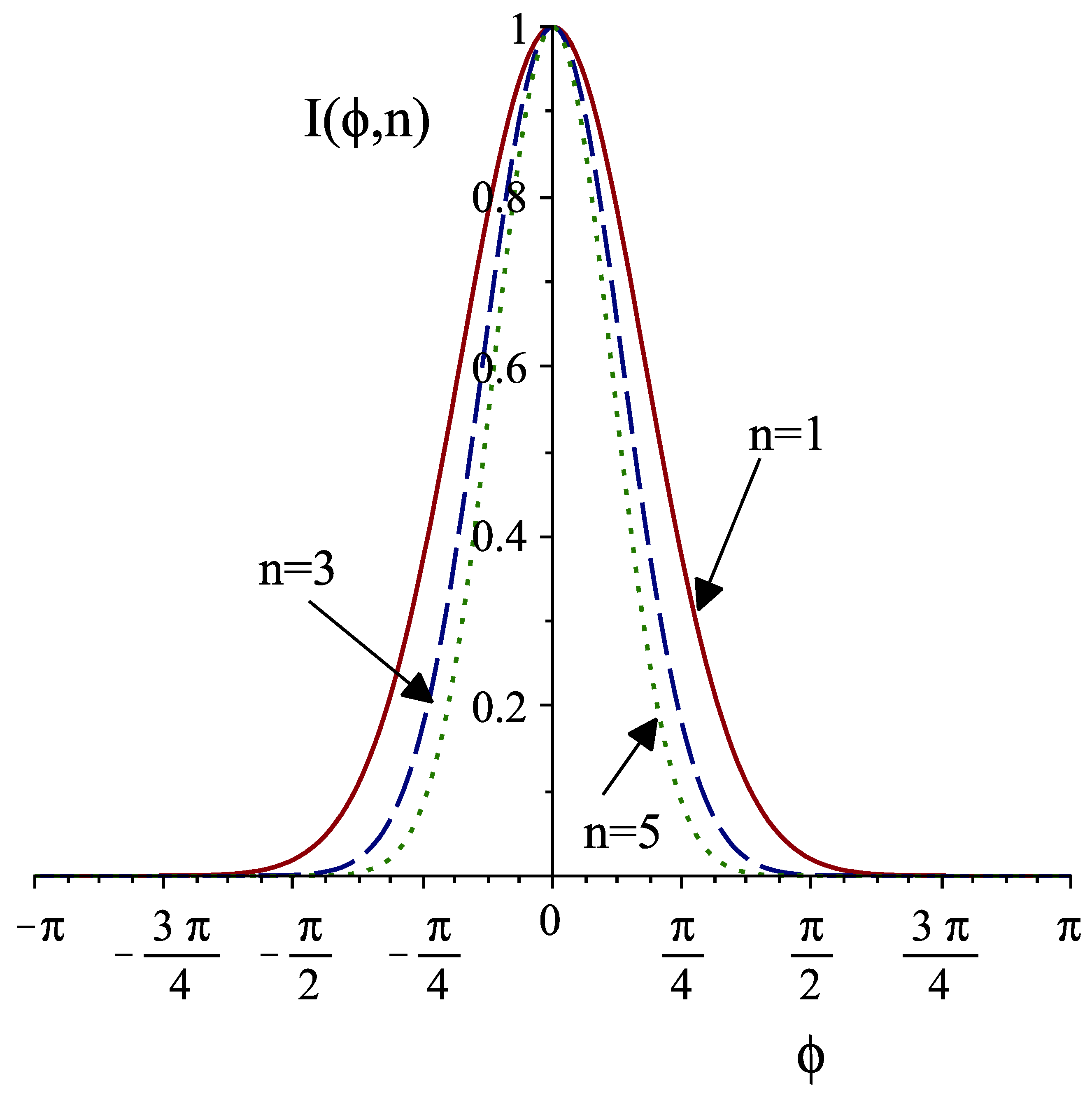
The final expression is obtained by a Taylor expansion of the trigonometric functions around the bunch center; the profile, therefore, results in a more simple Gaussian form. With the parameters used for the evaluation of Figure 2 in terms of phase difference and amplitude ratio, we display in Figure 3 the bunch profile for the fundamental harmonic only and for the simultaneous presence of the third or fifth harmonics. It is clear that the higher the harmonics content, the shorter the bunch will be at the cavity exit, due to the increased steepness of the resultant field around the reference electron.
5. FEL as a THz Radiator
In order to design an FEL operating at THz frequencies, simulation software that is capable of evaluating several of the characteristics of FEL sources has been developed. This code makes use of the electric field generated inside the double-frequency cavity, which is used as a phase-matching device, as described in the previous paragraph. The simulation considers an FEL device based on the main parameters reported in Table 1. The electrons generated and accelerated by a Linac are injected into the two-frequency cavity that is fed with the fundamental (3 GHz) and fifth harmonic and that is set, according to Table 1, in order to distribute the electrons according to Equation (6).
The simulation reported in Figure 4 shows the electron distribution in the longitudinal phase space at the cavity exit. During the transport toward the magnetic undulator, the particles continue to bunch due to ballistic effects; therefore, the peak current continues to increase. We have previously seen that the electron should enter the wiggler with the ideal distribution in the phase space to reduce the negative interference in order to enhance the extraction efficiency during its passage in the interaction region. To do so, a variable free propagation space may be considered a further optimization tool.
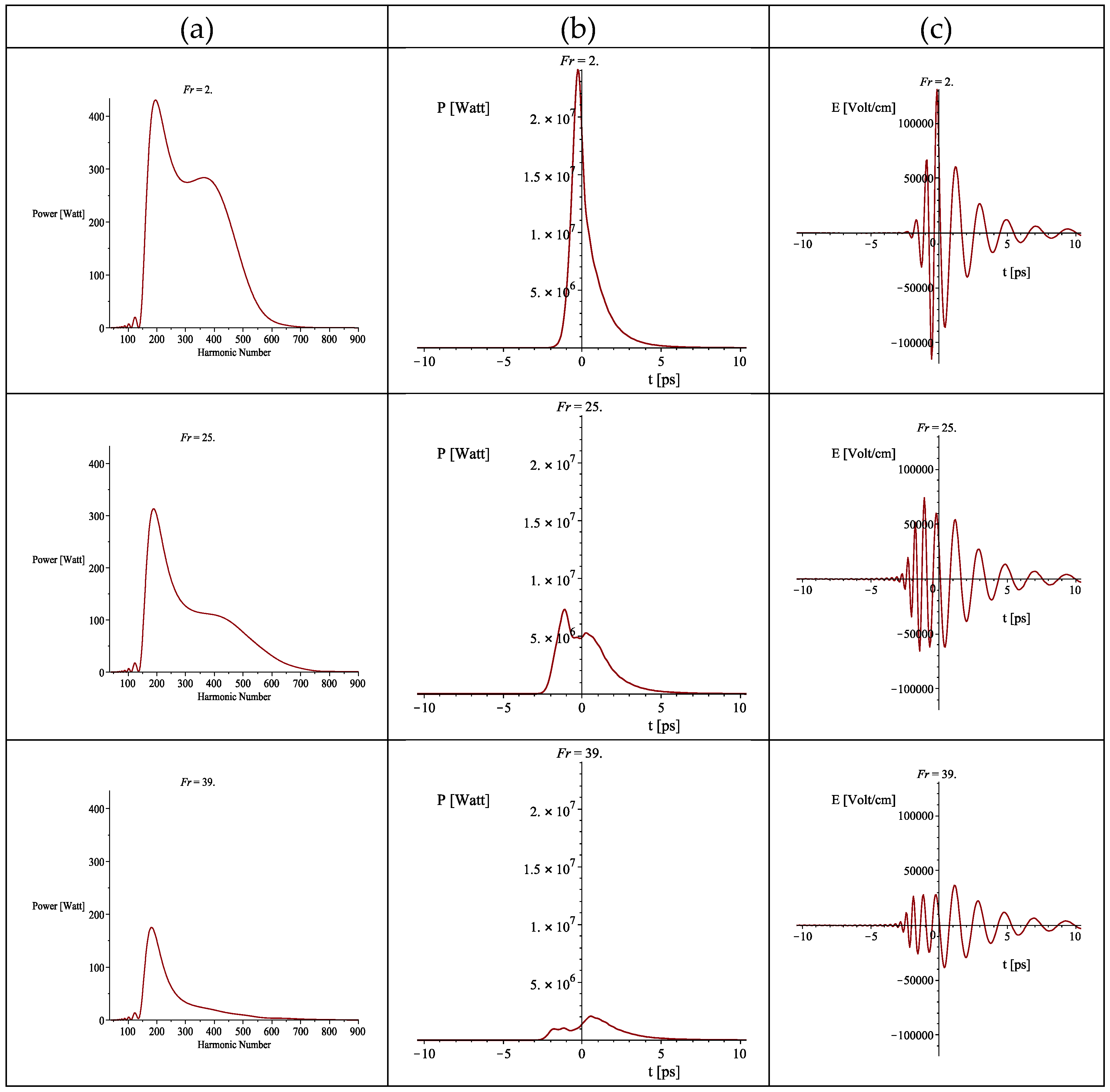
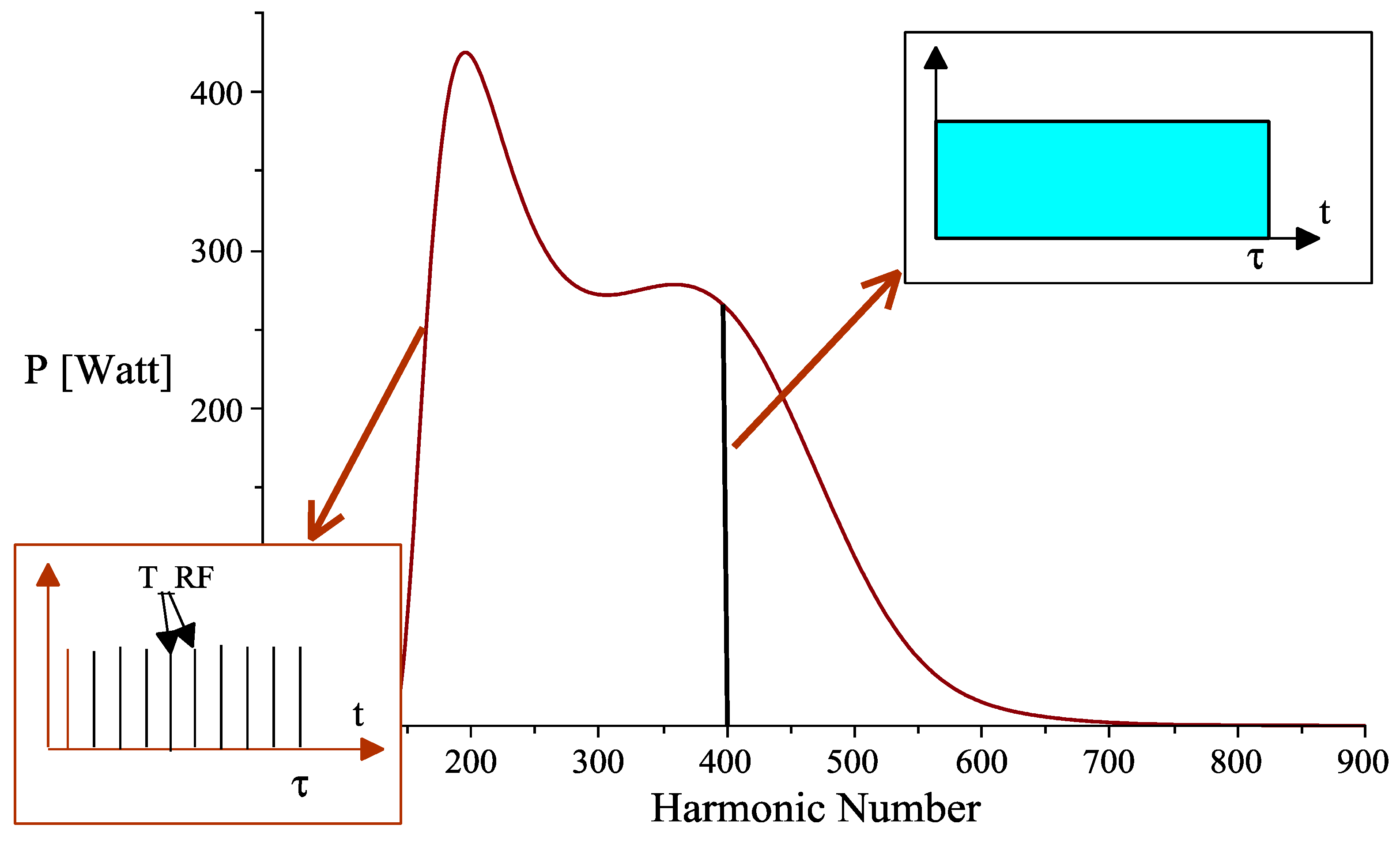
To clearly understand the effects of the drift space, we have analyzed the modification of the output power spectrum, averaged over the macropulse, during the propagation in a drift space, between the end of the two-frequency cavity and the undulator entrance, over a range of 36 cm. Analyzing Figure 5 (column (a)), we can observe that degradation occurs starting from about 7–8 cm from the cavity exit, and that at the end of the drift, it is quite significant. This phenomenon can also be observed by analyzing the single radiation peak pulse and the associated electric field burst; a reduction in the power of about 50%, in the worst situation, is expected (see Figure 5 column (b)). An optimization can be performed acting on the parameters of the two-frequency cavity, such as the voltage on the fundamental and its harmonic, or their relative phase, in order to reduce the rotation in the phase space and let the ballistic propagation complete such rotation and realize the ideal phase-matching distribution. After the proper optimization, we obtain a spectrum that ranges from 0.5 to 1.5 THz with an integrated power over the macropulse duration and over the total spectral bandwidth, of about 90 kW (see Figure 6). It is very important to stress that with this device, due to the RF properties of the accelerator, which are expressed also by Equations (3)–(5), it is possible to isolate the single harmonic with an interferometer, for instance, still having an average power for the single frequency of the order of hundreds of watts. This is not possible with conventional THz sources. Moreover, another interesting result is that the single frequency, being a harmonic of the RF, has a temporal structure equal to that of the RF macropulse. In addition, we have to refer to the RF macropulse for its temporal coherence, which for conventional magnetrons and klystrons is usually quite good. On the other hand, if we look at the whole bandwidth, the temporal structure is the well-known train of microbunches separated by the RF period.
In conclusion, an FEL THz radiator can operate as a natural “frequency-comb” emitter or a single-frequency emitter; therefore, it can be considered as a convenient, flexible, and powerful source for the generation of coherent radiation in the THz spectral region.
6. Energy Recovery
Another way to improve the performances of broadband THz FELs is related to their efficiency. One of the problems suffered by RF accelerator-based FELs, both normal conducting and superconducting, is their relatively low overall efficiency. Considering the basic generation mechanism, the power extraction from the electron beam in favor of the radiation never exceeds 1/2N, where N is the number of periods of the undulator for the low-gain regime, and ρ is the Pierce parameter for the high-gain regime (see [6,13]). In both cases, the best expected efficiency is of the order of few percent. A possibility to increase the efficiency of an FEL is to design a scheme for recovering the electron beam kinetic energy remaining after the undulator interaction. The energy recovered can be used to accelerate a new bunch of electrons, thus lowering the accelerator radio-frequency power requirements. The possibility of managing a lower RF power, and at the same time an exhausted electron beam of low energy, is very useful when designing both the thermal load of the device and the beam dump for the electron exhausting. Generally speaking, there are two possibilities for energy recovery (ER). One is to recycle the electron beam after the undulator interaction. The second possibility is to recover only the energy of the electrons before the beam dumps.
This second technique is particularly useful when the accelerator is designed to be a superconductor due to the reduced losses related to the shunt impedance. This is a relevant point because it allows presenting some interesting solutions. Any RF cavity exhibits power loss related to the ohmic dissipation through the shunt impedance. Considering standard cavity geometry, it can be demonstrated [14] that the shunt impedance per unit length times the cell dimension over the Q factor of the cavity is of the order of 150 Ohm (). This leads us to a simplified but reasonable expression for the power loss as a function of frequency and surface resistance, which is again related to the frequency and conductivity of the material:
Here, V is the accelerating voltage, L is the accelerator length, RSurf is the surface resistance, G is a factor, expressed in ohm, that depends on the RF cavity geometry, ν and ω are the frequency and the pulsation, respectively, and σ is the conductivity of the metal with which the Linac is realized.
Let us first analyze the case of a copper Linac operating in a normal conducting regime (σ = 5.8 × 10⁷ ohm−1m−1) at room temperature, and the cavities’ geometry for which G = 280 ohm; the results are reported in Table 2 for two different operating RF frequencies.
For Case 1, at 3 GHz, we have about 1 MW of power loss, due to ohmic losses across the structure, before any power could be delivered for the acceleration of the beam. With the same parameters, but at 8 GHz of RF (Case 2), we get about one-half of the previous value. This means that if we want to accelerate a beam to a certain energy value, we first need to spend such an amount of power to charge the structure; the rest of the power of the RF source is delivered to the e-beam. The power loss scales with the inverse of the square root of the frequency.
If a Linac based on superconducting material, as niobium, is considered, we know that the two models, the Bardeen–Cooper–Schrieffer (BCS) theory and the two-fluid model [15], are well established and report the same results up to frequencies of about 10 GHz. The surface resistance is now expressed by the following relation:
From the experimental data and simulations reported in [15], the A and α parameters can be deduced, and therefore the surface resistance for the two RF regimes can be deduced as well. The power loss formal expression is the same with the only difference that the surface resistance increases more rapidly with the frequency; consequently, the power losses increase with the frequency as well. Table 3 reports the power loss data for the superconducting Linac, with the same gradient, at 4.2 K.
The values reported are greatly reduced with respect to the normal conducting operation. By the RF source point of view, this amount of loss is negligible; all the RF power would be delivered to the beam in this case. The only problem is that this power must be thermodynamically managed at 4.2 K.
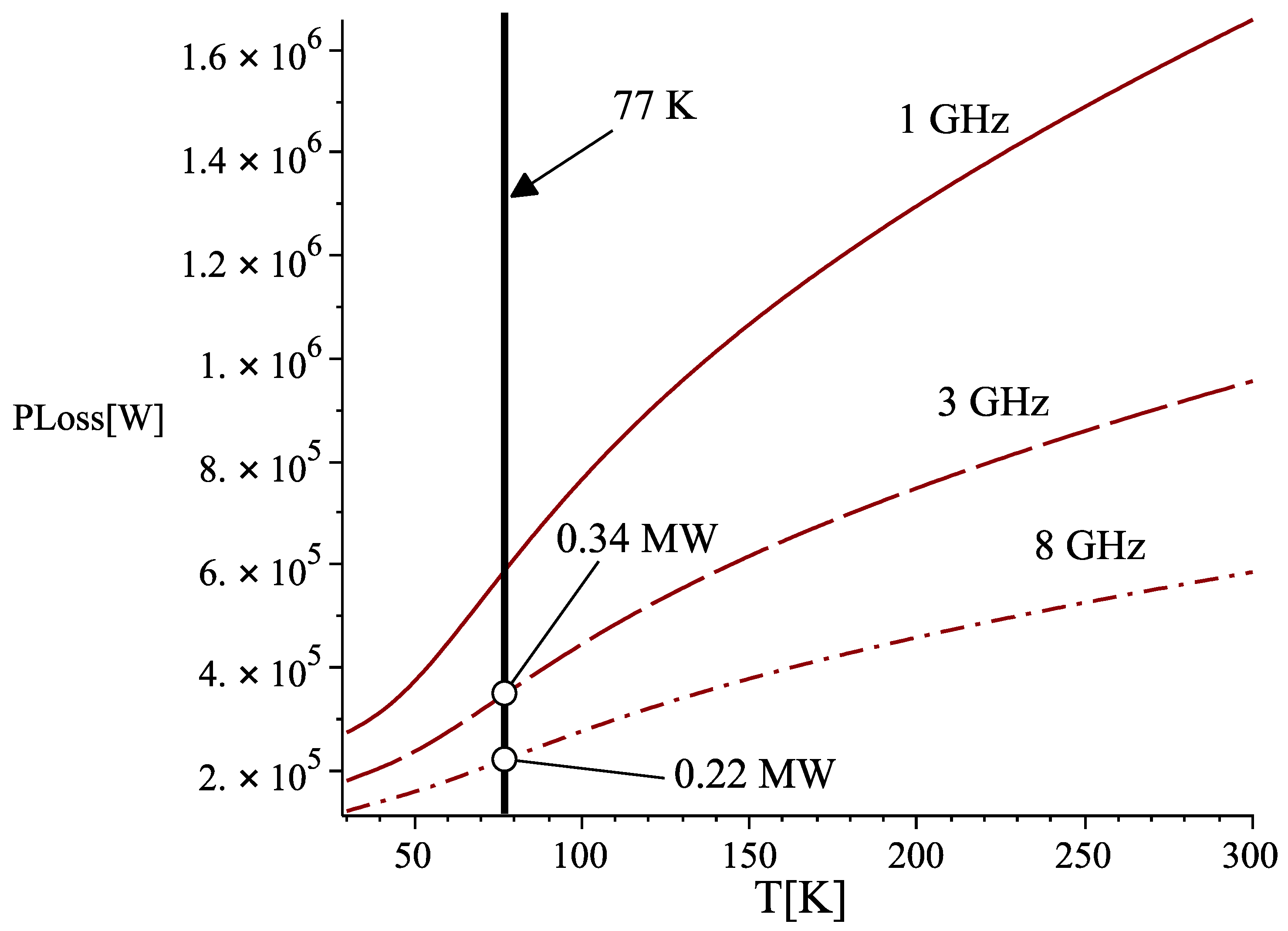
A third alternative is the use of normal-conducting metals, such as copper, at cryogenic temperatures. In fact, at low temperatures, the mean free path of electrons in metals increases; consequently, the electrons will not experience a constant electric field in a coherence length, but rather a variable one. These and other complex effects associated with the frequency, going under the name of an anomalous skin effect [16]. The result is that the classic ohm law, as we know it, is no longer valid, and the current must be calculated over the actual electron path. A simulation for a Linac with the previously reported values in Table 2 is displayed in Figure 7 for three frequencies.
The power losses decrease with the temperature, as expected, but again, higher frequencies exhibit lower losses. At liquid nitrogen temperatures, the power losses amount to about one-third with respect to the room temperature case. This is a quite good improvement for any energy recovery regime.
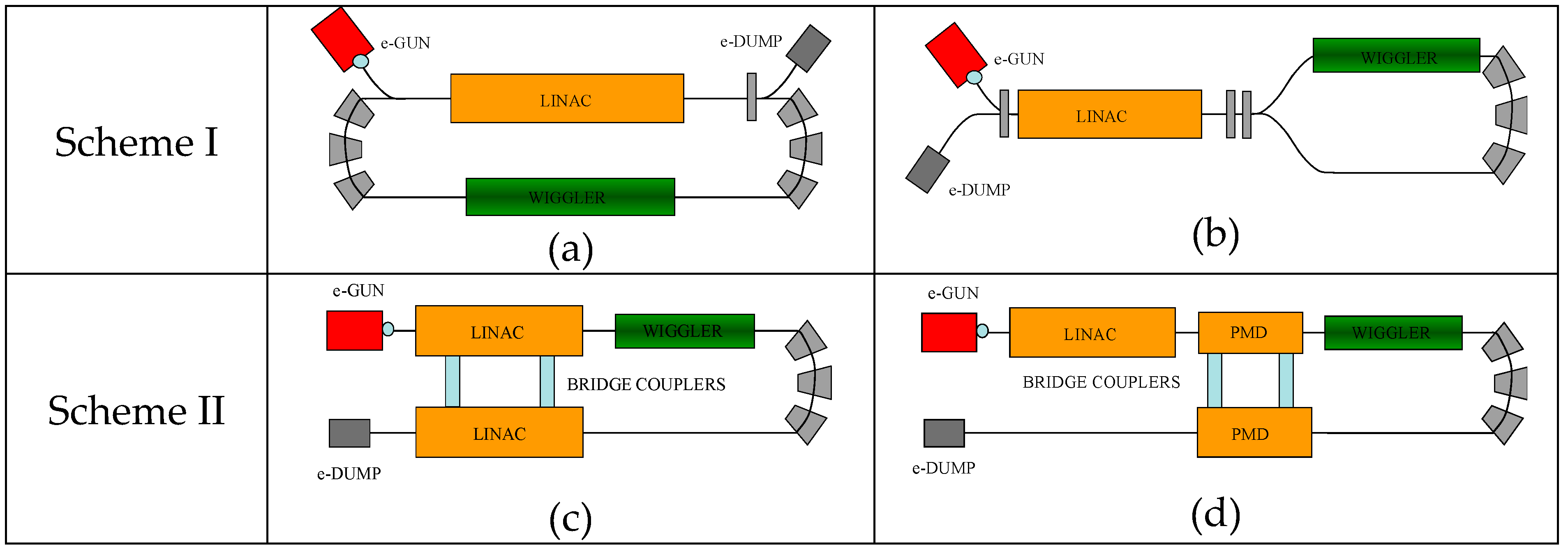
Once the amount of ohmic losses on the RF cavities that we have to deal with (both for the Linac and for the two-frequency cavity used as PMD) is clear, it is possible to face the problem about which kind of ER schemes might be appropriate for an FEL operating in the THz range. The most used is the so-called “same-cell” scheme in which a single RF structure acts as an accelerator in a first passage and a decelerator in a second passage. This scheme is usually the most favored choice due to economical reasons; in fact, the costs of the RF structure, especially if realized with superconductors, are quite high, and any saving in the RF power should not relapse on the RF structures (see Figure 8a).
An alternative to the same-cell scheme is the one reported in Figure 8b; in this variant, the electrons, after the Linac, follow a symmetric path where the magnetic undulator for the FEL radiation generation is placed in one of the two branches.
A second ER geometry is obtained when the beam, after the FEL interaction, is directed through a different decelerating structure. Generally, this second RF structure is similar to the accelerating Linac to which it must be strongly coupled in order to efficiently transfer the RF energy (see Figure 8 (c)). The “different-structure” scheme appears to be expensive because of the use of a second Linac structure. However, due to what has been discussed in the previous sections, THz generation, by means of free electron devices, requires low energy electron beams; therefore, the costs of the RF structures can still be affordable. For this reason, this scheme is under investigation at Frascati for the FEL-CATS. Moreover, this second scheme offers us the possibility of coupling the power of the exhausted beam directly into the two-frequency RF cavity: the PMD (see Figure 8d). This is a very interesting opportunity because the electrons, after the passage into the cavity and into the undulator, carry a memory of such an interaction by means of the shape of the current. Furthermore, by the use of the presented model of harmonic expansion (see Equations (3)–(5)), the shape of the field generated inside the PMD will be better tailored for the enhancement of the efficiency in the radiation generation mechanism. A semianalytical and numerical model is under study.
7. Conclusions
Innovative design schemes for the realization of a compact FEL source for operation in the THz spectral region have been discussed in this work. The proposed device, unlike conventional FELs, is not tuned by varying the electron energy or the undulator gap; instead, it is designed to emit several frequencies, which are the harmonics of the accelerator RF, within a broad spectral band. These characteristics are obtained through working on the coherent properties of the electron beam generated in a RF accelerator together with a proper manipulation of the electron distribution. The goal is to get the ideal energy-phase correlation that allows saturation-level emission without the use of an optical cavity. The features obtained are unique: the presence of the RF harmonics, which are spectrally very narrow, and that can be easily extracted make this device suitable for any spectroscopic application that requires a high spectral power density. A significant example is the diagnostic of magnetically confined plasma. Moreover, the presence of many narrow spectral components (related to the fundamental RF that can be as stable as 1 part over 106) allows creating a combination of them in a frequency “comb” that finds many applications in metrology (optical clock) in spectral phase interferometry and spectroscopy. A wide variety of features in a single device represent uniqueness in the laser source scenario.
Author Contributions
A.D. and G.P.G. have developed the theory about the coherent emission also in the case of energy-phase correlated electron beam. A.D. realised all the simulation codes for the electron dynamics, radiation emission and power losses in the RF structures. E.G. has controlled and verified the experiment feasibility of the device proposed.
Funding
This research received no external founding.
Conflicts of Interest
The authors declare no conflict of interest.
References
- Coutaz, J.L.; Garet, F.; Wallace, V.P. Principles of Terahertz Time-Domain Spectroscopy, 1st ed.; Jenny Stanford Publishing Pte. Ltd.: Singapore, 2018. [Google Scholar]
- Auston, D.H.; Glass, A.M. Optical generation of intense picosecond electrical pulses. Appl. Phys. Lett. 1972, 20, 398–399. [Google Scholar] [CrossRef]
- Wu, Q.; Zhang, X.C. Free space electro optic sampling of terahertz beams. Appl. Phys. Lett. 1995, 67, 3523–3525. [Google Scholar] [CrossRef]
- Schwinger, J. On the Classical Radiation of Accelerated Electrons. Phys. Rev. 1949, 75, 1912–1925. [Google Scholar] [CrossRef]
- Ginzburg, V.L.; Zheleznyakov, V.V. On the possible mechanisms of sporadic solar radio emission (radiation in an isotropic plasma). Sov. Astron. 1958, 2, 653–678. [Google Scholar]
- Dattoli, G.; Doria, A.; Sabia, E.; Artioli, M. Charged Beam Dynamics, Particle Accelerators and Free Electron Lasers, 1st ed; IOP Publishing Ltd.: Bristol, UK, 2017. [Google Scholar]
- Doria, A.; Bartolini, R.; Feinstein, J.; Gallerano, G.P.; Pantell, R.H. Coherent Emission and Gain from a Bunched Electron Beam. IEEE JQE 1993, 29, 1428–1436. [Google Scholar] [CrossRef]
- Doria, A.; Gallerano, G.P.; Giovenale, E.; Letardi, S.; Messina, G.; Ronsivalle, C. Enhancement of Coherent Emission by Energy-Phase Correlation in a Bunched Electron Beam. Phys. Rev. Lett. 1998, 80, 2841–2844. [Google Scholar] [CrossRef]
- Ciocci, F.; Bartolini, R.; Doria, A.; Gallerano, G.P.; Giovenale, E.; Kimmitt, M.F.; Renieri, G.M.A. Operation of a Compact Free Electron Laser in the Millimeter Wave Region with a Bunched Electron Beam. Phys. Rev. Lett. 1993, 70, 928–931. [Google Scholar] [CrossRef] [PubMed]
- Doria, A.; Gallerano, G.P.; Giovenale, E.; Messina, G.; Spassovsky, I. Enhanced Coherent Emission of Terahertz Radiation by Energy-Phase Correlation in a Bunched Electron Beam. Phys. Rev. Lett. 2004, 93, 264801. [Google Scholar] [CrossRef] [PubMed]
- Chin, Y.H. Double RF System for Bunch Shortening; ESG 108 LBL 29622; Lawrence Berkeley National Laboratory: Berkeley, CA, USA, 1990; pp. 1–17.
- Hofmann, A.; Myers, S. Beam Dynamics in a Double RF System. In Proceedings of the 11th Internationl Conference on High Energy Accelerators, CERN, Geneva, Switzerland, 7–11 July 1980; pp. 610–614. [Google Scholar]
- Dattoli, G.; Renieri, A. Experimental and theoretical aspects of free electron laser. In Laser Handbook Vol 4; Stitch, M.L., Bass, M., Eds.; North Holland Physics Publishing: Amsterdam, The Netherlands, 1985; pp. 1–141. [Google Scholar]
- Piel, H. Superconducting Cavities; CERN 89-04; CERN Accelerator School: Geneva, Switzerland, 1989; pp. 149–196. [Google Scholar]
- Matula, R.A. Electrical Resistivity of Copper, Gold, Palladium and Silver. J. Phys. Chem. Ref. Data 1979, 8, 1147–1298. [Google Scholar] [CrossRef]
- Reuter, G.E.H.; Sondheimer, E.H. The Theory of the Anomalous Skin Effect in Metals. Proc. R. Soc. A 1948, 195, 336–364. [Google Scholar] [CrossRef]
Figure 1.
Electron distribution in the longitudinal phase space while traveling along the magnetic undulator. Frame = 1 (a) represents the undulator entrance; Frame = 100 (b) represents the undulator center; and Frame = 200 (c) represents the undulator end.
Figure 1.
Electron distribution in the longitudinal phase space while traveling along the magnetic undulator. Frame = 1 (a) represents the undulator entrance; Frame = 100 (b) represents the undulator center; and Frame = 200 (c) represents the undulator end.

Figure 2.
Electric potential in a two-frequency cavity as a function of the phase φ for the fundamental frequency, the third harmonic, and the resultant field given by Equation (7).
Figure 2.
Electric potential in a two-frequency cavity as a function of the phase φ for the fundamental frequency, the third harmonic, and the resultant field given by Equation (7).

Figure 3.
Longitudinal electron bunch profile expressed in terms of the phase φ, for the fundamental frequency and for the third and fifth added harmonics.
Figure 3.
Longitudinal electron bunch profile expressed in terms of the phase φ, for the fundamental frequency and for the third and fifth added harmonics.

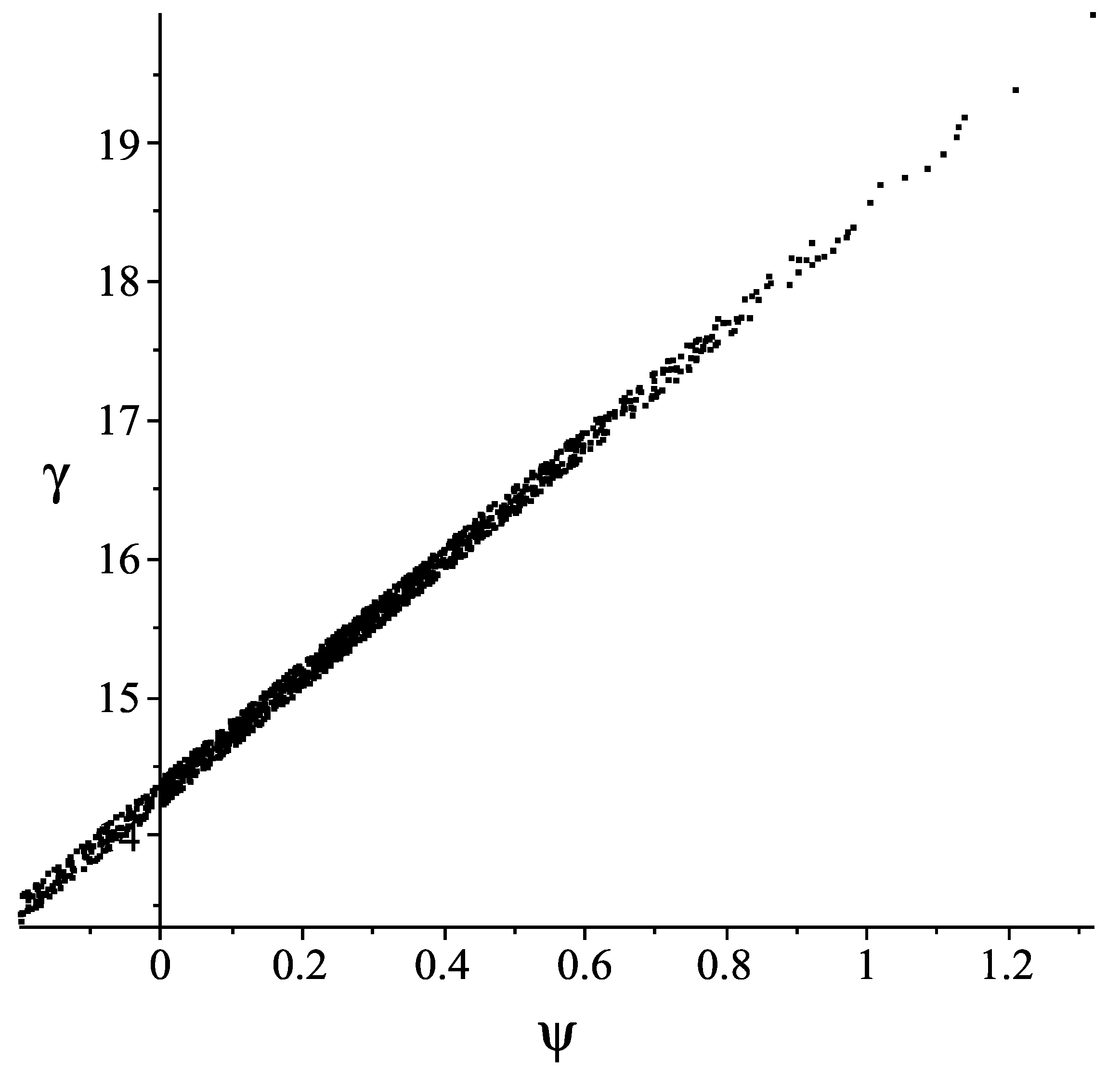
Figure 4.
Electron distribution, in the longitudinal phase space, at the two-frequency cavity exit.

Figure 5.
Simulation of the effect of a drift space in the terahertz (THz)-FEL emission. The three rows refer to three cases: Fr = 2 denotes 0 cm of drift space; Fr = 25 indicates 18 cm of drift space, and Fr = 39 represents 36 cm of drift space. Column (a) reports the radiation power spectrum; column (b) indicates the radiation peak power time profile, and column (c) shows the peak electric field as a function of time.

Figure 6.
Simulation of the optimized radiation power spectrum emitted as a comb of frequencies related to the harmonics of the fundamental RF (νRF = 3 GHz).
Figure 6.
Simulation of the optimized radiation power spectrum emitted as a comb of frequencies related to the harmonics of the fundamental RF (νRF = 3 GHz).

Figure 7.
Linac power loss behavior as a function of temperature and frequencies as follows from the anomalous skin effect theory.
Figure 7.
Linac power loss behavior as a function of temperature and frequencies as follows from the anomalous skin effect theory.

Figure 8.
Energy recovery schemes suitable for THz-FELs. (a) “Same-cell” scheme. (b) Alternative “same-cell” scheme. (c) Two-cavity scheme with Bridge Couplers. (d) Two-cavity scheme with PMDs.
Figure 8.
Energy recovery schemes suitable for THz-FELs. (a) “Same-cell” scheme. (b) Alternative “same-cell” scheme. (c) Two-cavity scheme with Bridge Couplers. (d) Two-cavity scheme with PMDs.


Table 1.
Main parameters of the free electron laser (FEL) simulation.
| Parameter Definition | Parameter Value |
|---|---|
| Electron Energy | E = 7.5 [MeV] (γ = 15) |
| Average Current (over the Macropulse) | IAV = 560 [mA] |
| Peak Current (over the Microbunch after the Two-Frequency Cavity) | Ip = 77 [A] |
| Microbunch Duration | τel = 700 [fs] |
| Radio Frequency (RF) | νRF = 3 [GHz] |
| Harmonic Number | n = 5 |
| Harmonic Relative Amplitude | k = –0.6 |
| Phase of the Fundamental (RF) | ∅s = 0 |
| Phase of the Harmonic | ∅n = π |
| Undulator Period | λu = 2.5 [cm] |
| Undulator Parameter | K = 1.45 |
| Number of Undulator Periods | N = 5 |
| Waveguide Vertical Gap | b = 0.154 [cm] |
Table 2.
Linac power losses, at room temperature, for two radio frequency (RF) values.
| Case 1: | ν = 3 GHz | L = 1 m | V = 7.5 MV | RSurf = 1.43 × 10⁻² ohm | PLoss = 0.96 MW |
| Case 2: | ν = 8 GHz | L = 1 m | V = 7.5 MV | RSurf = 2.33 × 10⁻² ohm | PLoss = 0.58 MW |
Table 3.
Linac power losses, at liquid helium temperature, for two RF values.
| Case 1: | ν = 3 GHz | L = 1 m | V = 7.5 MV | RSurf = 2.50 × 10⁻⁶ ohm | PLoss = 166 W |
| Case 2: | ν = 8 GHz | L = 1 m | V = 7.5 MV | RSurf = 1.75 × 10⁻⁵ ohm | PLoss = 445 W |
© 2019 by the authors. Licensee MDPI, Basel, Switzerland. This article is an open access article distributed under the terms and conditions of the Creative Commons Attribution (CC BY) license (http://creativecommons.org/licenses/by/4.0/).
Share and Cite
MDPI and ACS Style
Doria, A.; Gallerano, G.P.; Giovenale, E. Novel Schemes for Compact FELs in the THz Region. Condens. Matter 2019, 4, 90. https://0-doi-org.brum.beds.ac.uk/10.3390/condmat4040090
AMA Style
Doria A, Gallerano GP, Giovenale E. Novel Schemes for Compact FELs in the THz Region. Condensed Matter. 2019; 4(4):90. https://0-doi-org.brum.beds.ac.uk/10.3390/condmat4040090
Chicago/Turabian StyleDoria, Andrea, Gian Piero Gallerano, and Emilio Giovenale. 2019. "Novel Schemes for Compact FELs in the THz Region" Condensed Matter 4, no. 4: 90. https://0-doi-org.brum.beds.ac.uk/10.3390/condmat4040090