Unconventional Magnetism in Layered Transition Metal Dichalcogenides


Laboratory for Muon Spin Spectroscopy, Paul Scherrer Institute, CH-5232 Villigen PSI, Switzerland
Condens. Matter 2020, 5(2), 42; https://0-doi-org.brum.beds.ac.uk/10.3390/condmat5020042
Submission received: 18 May 2020
/
Revised: 15 June 2020
/
Accepted: 17 June 2020
/
Published: 20 June 2020
(This article belongs to the Special Issue From Quantum Paraelectric/Ferroelectric Perovskite Oxides to High Temperature Superconducting Copper Oxides -- In Honor of Professor K.A. Müller for His Lifework)
Abstract
:In this contribution to the MDPI Condensed Matter issue in Honor of Nobel Laureate Professor K.A. Müller I review recent experimental progress on magnetism of semiconducting transition metal dichalcogenides (TMDs) from the local-magnetic probe point of view such as muon-spin rotation and discuss prospects for the creation of unique new device concepts with these materials. TMDs are the prominent class of layered materials, that exhibit a vast range of interesting properties including unconventional semiconducting, optical, and transport behavior originating from valley splitting. Until recently, this family has been missing one crucial member: magnetic semiconductor. The situation has changed over the past few years with the discovery of layered semiconducting magnetic crystals, for example CrI and VI. We have also very recently discovered unconventional magnetism in semiconducting Mo-based TMD systems 2H-MoTe and 2H-MoSe [Guguchia et. al., Science Advances 2018, 4(12)]. Moreover, we also show the evidence for the involvement of magnetism in semiconducting tungsten diselenide 2H-WSe. These results open a path to studying the interplay of 2D physics, semiconducting properties and magnetism in TMDs. It also opens up a host of new opportunities to obtain tunable magnetic semiconductors, forming the basis for spintronics.
PACS:
76.75.+i; 74.55.+v; 75.50.Pp1. Introduction
Spintronics, or spin-based electronics, is one of the promising next generation information technology [1,2]. It makes use of the quantum property of electrons, such as spin, as information carriers and possesses potential advantages of speeding up the data processing, high circuit integration density, and low energy consumption. Magnetic semiconductors, combining the properties and advantages of both magnets and semiconductors, form the basis for spintronics. Not only ferromagnetic semiconductors, but also antiferromagnetic semiconductors were proposed to be natural candidates for integrating spintronics and traditional microelectronic functionalities in a single material [2]. All semiconductor spintronic devices act according to the following simple scheme: information is stored (written) into spins as a particular spin orientation; the spins, being attached to mobile electrons, carry the information along a wire; and the information is read and processed at a terminal. However, spintronics applications require novel magnetic semiconducting materials with high-temperature ferromagnetic or antiferromagnetic ordering of spins, which would simultaneously enable the conventional tunability of electronic properties and spintronic functionalities. Moreover, the materials should be produced as very stable thin layers to be incorporated in the devices.
Along these lines, transition metal dichalcogenides (TMDs), a family of two dimensional (2D) layered materials such as graphene, have appeared as the most promising platform due to their exciting mechanical, electronic and optoelectronic properties [3,4,5,6,7,8,9]. TMDs share the same formula, MX, where M is a transition metal and X is a chalcogen ion. They have a layered structure and crystallize in several polytypes, including 2H-, 1T-, 1T- and -type lattices. Much interest is focused on the cases where the transition metal M is either Molybdenum (Mo) or Tungsten (W). Hence, the 2H forms of these compounds are semiconducting and can be mechanically exfoliated to a monolayer. The unique properties of the TMDs, especially in the monolayer form, have triggered a wealth of device applications such as: magnetoresistance and spintronics, high on/off ratio transistors, optoelectronics, valley-optoelectronics, superconductors and hydrogen storage. Many of these interesting properties arise due to the strong spin-orbit interaction present in these materials arising from the presence of the heavy metal ion. While there are many studies focused on the spin-orbit coupling and the interesting consequences for electrical and optical properties in these materials, there are very limited, and mostly theoretical, studies on the intrinsic magnetism [10,11,12,13,14,15,16,17]. Theoretical work shows that, in the absence of crystalline imperfections, the Mo-based TMDs are nonmagnetic.
Combining a wealth of different technique, in particular the muon-spin rotation/relaxation (SR) technique, we discovered novel magnetism in these very stable semiconducting materials: molybdenum diteluride (MoTe) and molybdenum diselenide (MoSe) [9]. The results are published in a journal of the American Association for the Advancement of Science [9]. Here, I provide a short review of the previous results, show the new data for tungsten diselenide (2H-WSe) and discuss the importance of the presence of magnetism in semiconducting TMDs.
2. SR Technique: Very Sensitive Microscopic Magnetic Probe
The acronym SR stands for muon spin rotation, or relaxation, or resonance, depending respectively on whether the muon spin motion is predominantly a rotation (more precisely a precession around a magnetic field), or a relaxation towards an equilibrium direction, or a more complex dynamics dictated by the addition of short radio frequency pulses.
It is noteworthy that Prof. K. Alex Müller realised the importance and the strength of the SR technique in the studies of high temperature superconductors (HTSs) at the very early stage of the era of high- cuprates, as demonstrated in the pioneering papers [18,19,20]. Indeed, this technique allows us to study fundamental problems related to superconductivity [8,21,22,23,24,25,26,27,28,29].
Besides superconductivity, positive muons implanted into a sample serve as an extremely sensitive local probe to detect small internal magnetic fields and ordered magnetic volume fractions in the bulk of magnetic materials. SR can distinguish the volume fraction effect from the ordered moment size and thus, it is a particularly powerful tool to study the thermal or quantum evolution of both magnetic moment and magnetically ordered volume fraction in solid materials [30,31,32,33]. SR is also valuable for studying materials in which magnetic order is random or of short range. This makes SR a perfectly complementary technique to scattering techniques such as neutron diffraction, which is used to determine crystallographic and magnetic structures. Moreover, the SR technique has a unique time window (10 s to 10 s) for the study of magnetic fluctuations in materials, which is complementary to other experimental techniques such as neutron scattering, NMR, or magnetic susceptibility. With its unique capabilities, SR should be considered to play a leading role in determining magnetic phase diagrams and elucidating the quantum evolution from the paramagnetic to magnetic state in the semiconducting TMDs, which are interesting due to both fundamental and practical aspects. A brief introduction to the SR technique [34,35,36] is given below.
The SR method is based on the observation of the time evolution of the spin polarization (t) of the muon ensemble. A schematic layout of a SR experiment is shown in Figure 1a–c. In a SR experiments an intense beam ( = 29 MeV/c) of 100 % spin-polarized muons is stopped in the sample (see Figure 1a). Currently available instruments allow essentially a background free SR measurement at ambient pressure [37]. The positively charged muons thermalize in the sample at interstitial lattice sites, where they act as magnetic microprobes. In a magnetic material the muons spin precess in the local field at the muon site with the Larmor frequency = /(2 (muon gyromagnetic ratio /(2) = 135.5 MHz T). The muons implanted into the sample will decay after a mean life time of = 2.2 s, emitting a fast positron preferentially along their spin direction. Various detectors placed around the sample track the incoming and the outgoing (see Figure 1a). When the muon detector records the arrival of a in the specimen, the electronic clock starts. The clock is stopped when the decay positron is registered in one of the detectors, and the measured time interval is stored in a histogramming memory. In this way a positron-count versus time histogram is formed (Figure 1b). A muon decay event requires that within a certain time interval after a has stopped in the sample an is detected. This time interval extends usually over several muon lifetimes (e.g., 10 s). After a number of muons has stopped in the sample, one obtains a histogram for the forward () and the backward () detectors as shown in Figure 1b, which in the ideal case has the following form:
Here, the exponential factor accounts for the radioactive muon decay. (t) is the muon-spin polarization function with the unit vector ( = F,B) with respect to the incoming muon spin polarization. is number of positrons at the initial time t = 0. is a background contribution due to uncorrelated starts and stops. is the initial asymmetry, depending on different experimental factors, such as the detector solid angle, efficiency, absorption, and scattering of positrons in the material. Typical values of are between 0.2 and 0.3.
Since the positrons are emitted predominantly in the direction of the muon spin which precesses with , the forward and backward detectors will detect a signal oscillating with the same frequency. In order to remove the exponential decay due to the finite life time of the muon, the so-called asymmetry signal A(t) is calculated (see Figure 1c):
where (t) and (t) are the number of positrons detected in the forward and backward detectors, respectively. The quantities and depend sensitively on the spatial distribution and dynamical fluctuations of the magnetic environment of the muons. Hence, these functions allow us to study interesting physics of the investigated system.
In SR experiments two different magnetic field configurations are used: (i) Transverse field (TF) SR involves the application of an external field perpendicular to the initial direction of the muon spin polarization. The muon spin precesses around the transverse field, with a frequency that is proportional to the size of the field at the muon site in the material. (ii) In the longitudinal field (LF) configuration the magnetic field is applied parallel to the initial direction of the muon spin polarization. The time evolution of the muon spin polarization along its initial direction is measured in this configuration. Measurements are often carried out in the absence of external magnetic field, a configuration called zero-field (ZF) SR. In this configuration the frequency of an obtained SR signal is proportional to the internal magnetic field, from which the size of the ordered moment and thus the magnetic order parameter is calculated. The capability of studying materials in zero external field is a big advantage over other magnetic resonance techniques.
If the local magnetic field () at the muon site is pointing under an angle with respect to the initial muon spin polarization, the decay positron asymmetry is given by [33]:
where is the maximal value of the asymmetry. Further assuming that the random fields are isotropic and each component can be represented by a Gaussian distribution of width /, then a statistical average of this distribution yields:
This function was first obtained in a general stochastic treatment of Kubo and Toyabe [38]. The form of the distribution of internal magnetic fields influences the form of the SR signal [30,31,33]. Thus, by analysing the observed muon-spin time evolution, the magnetic field distribution inside the sample can be obtained. For clarity, Figure 1d–f shows the expected time evolution of the muon spin polarisation for three different cases of magnetically ordered polycrystaline sample: fully magnetic and magnetically homogeneous (d), full volume magnetic and inhomogeneous (e) and phase separation between magnetic and paramagnetic regions (f). The muons stopping in the homogeneous sample will sense the same magnetic field and their spin will precess around the internal field and the SR signal is characterised by maximum amplitude and zero depolarisation (Figure 1d). If there is an inhomogeneous static internal field in the sample, different muons will precess at slightly different frequencies. This leads to a progressive dephasing of the SR signal, and the oscillations in the SR time spectra will be damped (see Figure 1e). In some cases the signal is strongly damped, so that the oscillation will not be observed, and the resulting muon spin polarization will be averaged out to zero. Then, at a magnetic phase transition, if no wiggles are observed in the SR signal, one expects a drop in the effective initial asymmetry from in the paramagnetic state to = 1/3 in the ordered state [30]. However, this effect could also be due to fluctuations of the internal field. SR is capable of distinguishing between these two possibilities by performing an LF-SR experiment. In a longitudinal field inhomogeneous line broadening and fluctuations lead to different SR time spectra. Since muons stop uniformly throughout a sample, and the amplitudes of the SR signals arising from the different regions of the sample are proportional to the volume of the sample occupied by a particular phase, the presence of paramagnetic regions will result in the reduction of the signal amplitude as shown in Figure 1f. This schematics is a simple illustration of the fact that SR is capable to provide quantitative information on coexisting and competing phases in a material.
3. Results
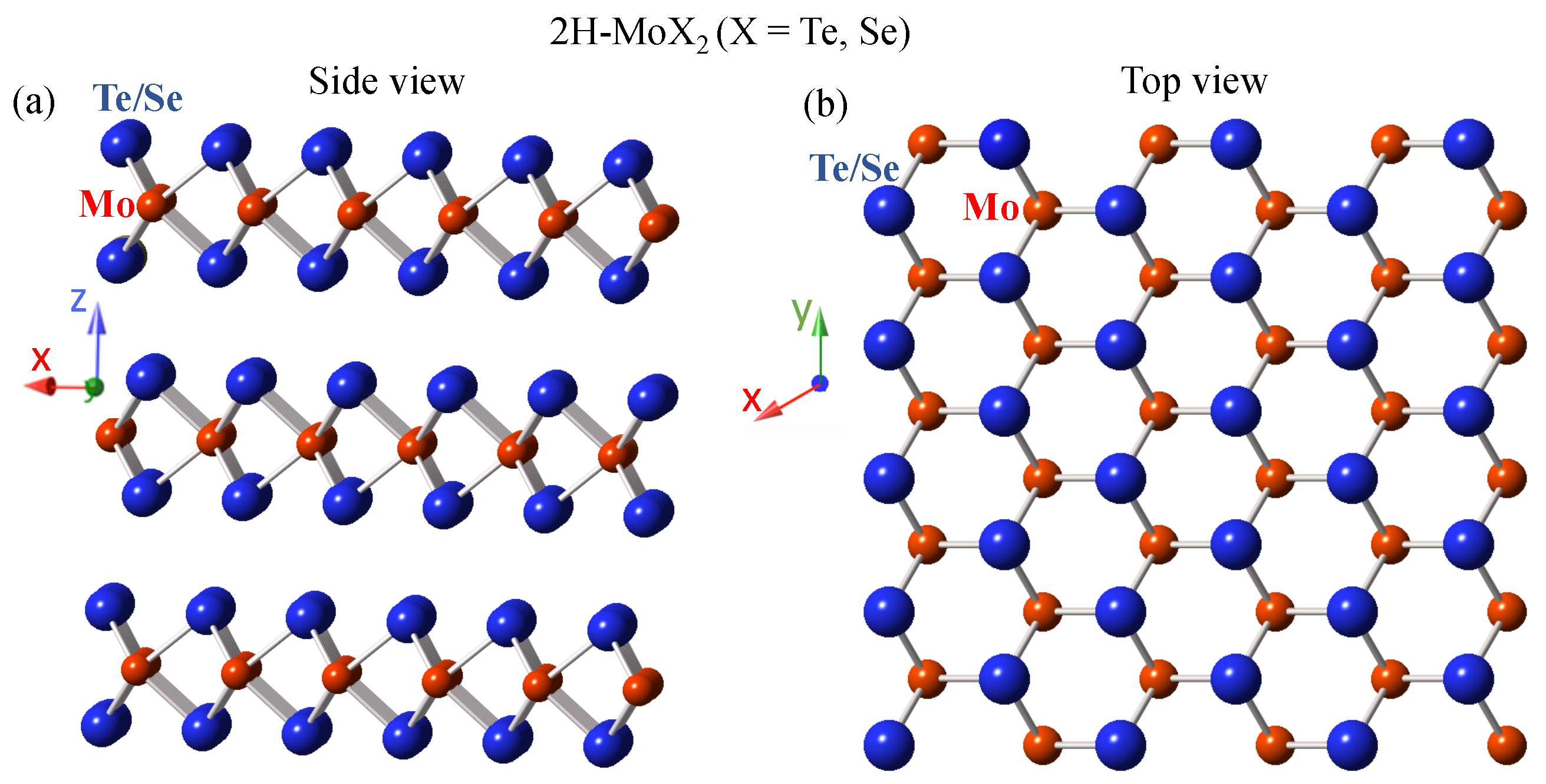
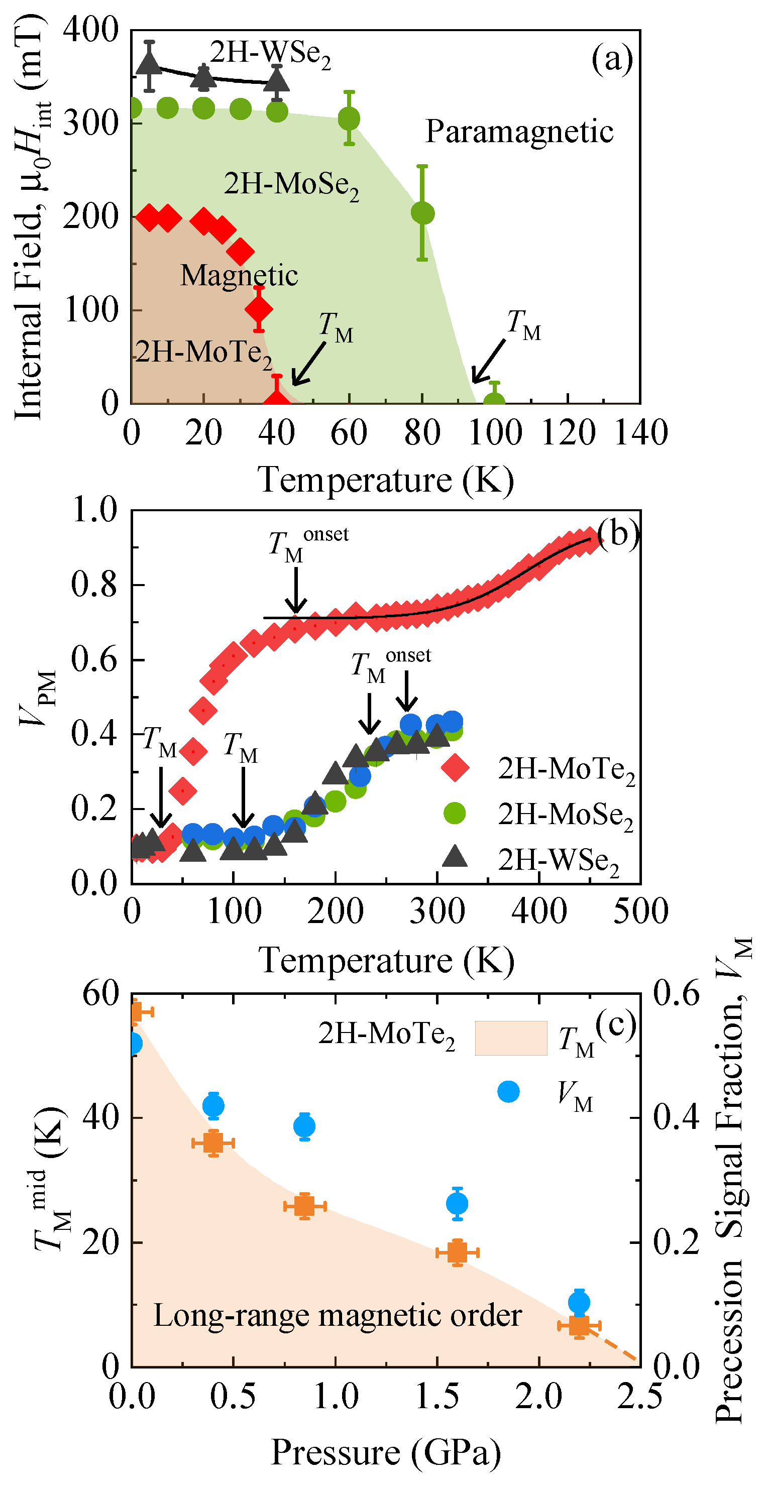
As we showed in our previous work, a spontaneous muon spin precession with a well-defined frequency was observed for both 2H-MoTe and 2H-MoSe at low temperatures (structural representation of the hexagonal 2H structure is shown in Figure 2). Moreover, muon spin precession was also observed for W-based TMD semiconductor 2H-WSe. The observation of a spontaneous muon spin precession is a clear signature of the occurrence of a static magnetic state in these semiconducting systems at low temperatures. Figure 3 shows the comparison of zero-field SR time spectra, recorded at T = 5 K, between semimetallic orthorhombic -MoTe and semiconducting hexagonal 2H-MoTe samples. It is interesting that while 2H-MoTe showed coherent oscillations and thus the static magnetism, -MoTe gave a typical paramagnetic response from the whole sample volume. This indicates that static magnetism was a property for semiconducting 2H phase (Figure 2). The precession frequency was proportional to the local internal field at the muon site, which is shown in Figure 4a as a function of temperature for both 2H-MoTe and 2H-MoSe samples. A few points for 2H-WSe were also shown. There was a smooth increase of below ≃ 40 K and 100 K for 2H-MoTe and 2H-MoSe, respectively. The internal field reached the saturated value of ≃ 200 mT and 300 mT at low temperatures, for 2H-MoTe and 2H-MoSe, respectively. For 2H-WSe, an even higher internal field value of ≃ 350 mT was observed. A higher value of and for 2H-MoSe and 2H-WSe as compared to values for 2H-MoTe might be related to the distinct magnetic structures in these systems.
Although SR measurements revealed the homogeneous internal magnetic fields in 2H-MoTe and 2H-MoSe below ≃ 40 K and 100 K, respectively, we observed that short-range (inhomogeneous) magnetism occurred at much higher temperatures. Figure 4b displays the paramagnetic fraction as a function of temperature for both samples. In MoTe, at 450 K, exhibited nearly a maximum value and decreases with decreasing temperature and tends to saturate below 300 K. This ∼30 % reduction of can arise for few different reasons and it was most likely due to the presence of a muonium fraction. In muonium, a bound state formed by a positive muon and an electron, may form in semiconductors [41]. In the bound state, the muon is much more sensitive to magnetic fields than as a free probe, because its magnetic moment couples to the much larger electron magnetic moment, thus amplifying the depolarization effects. Therefore, even small variations of the internal magnetic field may cause the loss of asymmetry such as that observed in 2H-MoTe at high temperatures. However, there was an additional decrease of starting below ∼ 180 K, which was due to the appearance of inhomogeneous short-range magnetism and continued to reduce until it reached the minimum value ≃ 0.1 at the long-range magnetic ordering temperature ≃ 40 K, below which zero-field SR showed a well defined uniform internal magnetic field. This implies that the long range magnetic order was achieved only below ≃ 40 K, while the short range magnetism appeared at higher temperature ∼ 180 K. The same was also observed in MoSe, i.e., the short range magnetism appeared below ∼ 250 K, while the long-range order was achieved below ≃ 100 K. The onset temperature of short range magnetism in 2H-WSe was close to the one for 2H-MoSe (see Figure 4b). This suggests the presence of magnetic correlations in 2H-MoSe and 2H-WSe almost at room temperature, which may render TMDs useful for novel optoelectronics–spintronics applications. Moreover, we determined that hydrostatic pressure [42,43] had a significant effect on the magnetic properties of these materials. Namely, we saw a large suppression of both the magnetically ordered fraction and the magnetic order temperature of 2H-MoTe as a function of pressure (Figure 4c). The magnetism was nearly fully suppressed within 2.5 GPa. On the other hand, 2H structure remained stable up to much higher pressure of p∼ 11 GPa (the results will be reported elsewhere), which implies that the suppression of magnetism in 2H-MoTe did not originate from the structural modifications. This strong pressure dependence of magnetism is very encouraging, because it indicates that one can have quantum control, in addition to thermal control, over the magnetic properties.
The presence of magnetism in MoTe and MoSe was substantiated by temperature dependent macroscopic magnetisation measurements (see Figure 5a,b). A large difference between zero-field cooled (ZFC) and field-cooled (FC) magnetic moments was seen for both samples. The samples showed a combination of a temperature-independent diamagnetism, small van Vleck-type paramagnetism (which is determined by the energy separation of bonding and anti-bonding states -. - is proportional to the band gap ) and a magnetic contribution that onset near 230 K and 180 K for MoSe and MoTe, respectively. The difference between the FC and ZFC response suggests that different magnetic domains tended to cancel out (anti-align) after ZFC. If we do field-cooling, then the domains align. The onset temperatures of hysteresis 230 K and 180 K for MoSe and MoTe, respectively, were close to the temperature below which SR experiments showed the appearance of inhomogeneous magnetism (see Figure 4b). This means that below some small magnetic domains (droplets of magnetic order) formed, which produced inhomogeneous magnetic fields and resulted in the absence of coherent oscillations in the SR signal. Instead, the various magnetic fields produced in the sample gave rise to a strong damping of the muon asymmetry, which we clearly d at = 180 K in MoTe and = 250 K in MoSe. SR observed homogeneous magnetism below ≃ 40 K and 100 K for MoTe and MoSe, respectively, and the anomalies (such as an additional increase of the moment and of the difference) at around these temperatures could also be seen in magnetization data. We note that for the sample MoSe the magnetic contribution dominated over the diamagnetism, gave rise to total positive moment. In contrast, for MoTe diamagnetism dominated over the magnetic contribution. Assuming that the core diamagnetism is nearly the same in these materials, this difference might be related to a distinct magnetic structures of MoTe and MoSe. Separation between ZFC and FC curves, observed at low temperatures, does not necessarily indicate the ferromagnetic (FM) order. It could be consistent with the canted antiferromagnetic (AFM) structure, i.e., AFM structure with some weak net FM moment. Since magnetic contribution dominates over the diamagnetism in MoSe, its magnetic structure most likely exhibits larger net FM moment than the one for MoTe.
4. Summary and Discussion
The SR measurements establish 2H-MoTe, 2H-MoSe and 2H-WSe as intrinsic magnetic, moderate bandgap semiconductors [9]. The SR results demonstrate magnetic order below ≃ 40 and 100 K for MoTe and MoSe, respectively. These results came as a surprise since the previous theoretical work [11] and simple chemical bonding considerations indicate that the Mo atoms in these samples are in a nonmagnetic 4 configuration. To understand the origin of magnetism, we carried out [9] the detailed investigation of the presence of defects and examined their magnetic properties by combination of the high-resolution STM [44] and Hubbard corrected DFT+U calculations [45] for Mo-based systems. STM measurements demonstrate the presence of intrinsic dilute self-organized defects. Note that two major defects, i.e., metal-vacancies (Figure 6a) and chalcogen-antisites (Figure 6b) (where a molybdenum atom substitutes the Tellurium/Selenium atom) were found in these materials. The defect concentration is small (∼ 0.5–1%), but defects are found to have a large electronic impact. Moreover, DFT indicates that the chalcogen-antisite defects Mo are magnetic, while metal-vacancy defects Mo do not introduce a significant local moment. Although, DFT shows the magnetic defects in these systems, it is difficult to understand how the low-density of the chalcogen-antisite defects can give rise to homogeneous internal magnetic fields, observed in 2H-MoTe and 2H-MoSe, indicative of long-range magnetic order. This may be possible if these defects have electronic coupling to the semiconductor valence electrons. The presence of such spin-polarized itinerant electrons would imply that these materials are dilute magnetic semiconductors. This idea may be partly supported by the recent report on the observation of hidden spin-polarized states in the bulk MoTe [46]. Although the exact link between SR and STM/DFT results [9] in 2H-MoTe and 2H-MoSe is not yet clear, both results together constitute a first strong evidence concerning the relevance of magnetic order in the TMDs physics. Defect induced, layer-modulated magnetism was recently reported for ultrathin metallic system PtSe [47]. Ferromagnetism is also observed in VSe monolayers. However, this system is characterized by a high density of states at the Fermi level [48], which is different from the systems 2H-MoTe, 2H-MoSe and 2H-WSe, showing good semiconducting behavior. Thus, they open up a host of new opportunities to obtain tunable magnetic semiconductors, forming the basis for spintronics. Recently, there have been several reports on magnetism in W-based TMDs from bulk magnetisation measurements. Namely, the formation of ferromagnetism was reported for Vanadium doped WS [49] and WSe [50,51] monolayers with a small amount (∼0.5–4%) of V-content and the materials was classified as a dilute-magnetic semiconductor. We note that the mechanism behind the magnetic order in 2H-MoTe, 2H-MoSe and 2H-WSe with intrinsic magnetic defects and in WS with incorporation of small amount of Vanadium could be similar. Besides Mo- and W-based TMDs, a very interesting magnetic semiconducting TMD system is CrI [52]. Although the experimental investigations of bulk CrI date back to the 1960s, the temperature dependent magnetic and structural properties have only recently been reported [53]. Standard magnetization measurements show that CrI is an anisotropic ferromagnet below the = 61 K, with its easy axis pointing perpendicular to the layers. Evidence for a second unexpected magnetic phase transition at T = 50 K is found both in the bulk and in atomically thin crystals of CrI [52]. It is important to emphasize that neither the nature nor the details of the ensuing magnetic state in CrI are currently understood. To date, the origin of the novel magnetic order in Mo/W-based TMDs and the nature of complex magnetism in CrI is not understood. To fully exploit the magnetic properties of these TMD semiconductors, future works needs to address these important issues. It is essential to make use of pressure, strain, organic cation intercalation, light illumination [54], and particle irradiation as tuning parameters for bulk material to explore the precise role of itinerant carriers and the specific type of defects in the formation of magnetism in Mo- and W-based TMDs.
Previously, magnetic semiconductors have been synthesized in a range of thin film and crystal materials [55,56,57]. Much interest has been focused on the III-V (GaAs) [55,56] and I-II-V (LiZnAs) [57,58] semiconductor class, where a small concentration of some magnetic ions, in particular Mn, can be incorporated by substituting for the group II (Zn,) and III (Ga) cations of the host semiconductor. Numerous technical challenges in making uniform magnetic semiconducting materials have been overcome in recent years, but formidable challenges still remain in producing stable, high-quality materials with high . For instance, GaMnAs has poor chemical solubility and can not be grown as a bulk material. Only MBE films are available and only as a p-type system. LiZnMnAs has high chemical solubility and can be grown as a bulk material. However, no films of LiZnMnAs are available. Our present systems offer an alternative route to synthesize magnetic semiconducting materials with the following advantages:
- High quality bulk samples of Mo/W-based semiconducting TMDs can be grown. The systems can be doped to make both n-type and p-type semiconductors available.
- The materials are cleavable down to a monolayer thickness and readily grown in large-area form. As it is well established in these materials, the bandgap is strongly dependent on the thickness, providing tunability over the semiconductor properties.
- The chemical potential and electric field in thin films are easily tuned by electrostatic gates, opening the possibility to tune magnetism, as demonstrated in GaAs.
- Finally, these materials can be easily layered by van der Waals heteroepitaxy, allowing the creation of unique new device concepts. For instance, one can grow the heterostructure of the magnetic TMDs (2H-MoTe, 2H-MoSe, 2H-WSe) and superconducting Weyl semimetal [3] (-MoTe) or the heterostructure of the magnetic TMDs (2H-MoTe, 2H-MoSe, 2H-WSe) and topological insulator (TI) [59,60] (BiSe) and study exotic magnetic/superconducting properties at the interface [61,62,63]. Even though the SC in the bulk can be topologically trivial, the robust Z related topological states at the surface or at the interfaces is expected to feature helical or other exotic Cooper pairing due to spin-momentum locking [64], and the external magnet field induced vortex line can support Majorana fermions. When a topological insulator/metal is in contact with a ferromagnet, both time reversal and inversion symmetries are broken at the interface. An energy gap is formed at the TI surface, and its electrons gain a net magnetic moment through short-range exchange interactions. Magnetic/superconducting proximity effects at the interface between magnet and Weyl semimetal (Figure 7a) or magnet and topological insulators (Figure 7b) is considered to have great potential in spintronics as, in principle, it allows realizing the quantum anomalous Hall and topological magneto-electric effects. However, detailed experimental investigations of induced magnetism at the interfaces has remained a challenge. Low-energy SR [63,65] experiments, which allows to probe the magnetism and superconductivity as a function of distance from the free surface to the interface, will be crucial to address the interesting magnetic/superconducting aspects of the interfaces.
Funding
Zurab Guguchia gratefully acknowledges the financial support by the Swiss National Science Foundation (SNSF-fellowships P2ZHP2-161980 and P300P2-177832).
Acknowledgments
The author started to investigate magnetism in 2H-MoTe with SR, during his postdoctoral research in the Laboratory for Muon Spin Spectroscopy at the Paul Scherrer Institute, Switzerland, working with Rustem Khasanov, Alex Amato and Elvezio Morenzoni. Later on, he joined the group of Yasutomo Uemura at the Columbia University, where he spent two years and carried out extended studies of transition metal dichalcogenides in collaboration with the groups of Abhay Pasupathy and Simon Billinge at the Columbia University and the group of Elton Santos at the Queens University of Belfast. This work benefited from a combination of various experimental techniques and from DFT calculations. Samples were provided by Fabian von Rohr from the University of Zürich and by Daniel Rhodes from the Columbia University. The SR experiments were carried out at the Swiss Muon Source (SS) of the Paul Scherrer Institute using low background GPS (M3 beamline) [37] and high pressure GPD (E1 beamline) [42] instruments. The SR time spectra were analyzed using the free software package MUSRFIT [66]. STM and SQUID experiments were carried out at the Columbia University. DFT calculations were performed at the Queens University of Belfast. X-ray PDF experiments were carried out at the Brookhaven National Laboratory. The author thank all the people involved in this project.
Conflicts of Interest
The authors declare no conflict of interest.
References
- Lombardi, G.C.; Bianchi, G.E. Spintronics: Materials, Applications and Devices; Nova Science Pub Inc.: Hauppauge, NY, USA, 2009. [Google Scholar]
- Jungwirth, T.; Marti, X.; Wadley, P.; Wunderlich, J. Antiferromagnetic spintronics. Nat. Nanotechnol. 2016, 11, 231–241. [Google Scholar] [CrossRef] [PubMed]
- Soluyanov, A.A.; Gresch, D.; Wang, Z.; Wu, Q.; Troyer, M.; Dai, X.; Bernevig, B.A. Type-II Weyl semimetals. Nature 2015, 527, 495–498. [Google Scholar] [CrossRef] [PubMed] [Green Version]
- Xu, X.; Yao, W.; Xiao, D.; Heinz, T.F. Spin and pseudospins in layered transition metal dichalcogenides. Nat. Phys. 2014, 10, 343–350. [Google Scholar] [CrossRef]
- Ali, M.N.; Xiong, J.; Flynn, S.; Tao, J.; Gibson, Q.D.; Schoop, L.M.; Liang, T.; Haldolaarachchige, N.; Hirschberger, M.; Ong, N.P.; et al. Large, non-saturating magnetoresistance in WTe2. Nature 2014, 514, 205–208. [Google Scholar] [CrossRef] [PubMed] [Green Version]
- Qian, X.; Liu, J.; Fu, L.; Li, J. Quantum spin Hall effect in two-dimensional transition metal dichalcogenides. Science 2014, 346, 1344–1347. [Google Scholar] [CrossRef] [Green Version]
- Costanzo, D.; Jo, S.; Berger, H.; Morpurgo, A.F. Gate-induced superconductivity in atomically thin MoS2 crystals. Nat. Nanotechnol. 2016, 11, 339. [Google Scholar] [CrossRef] [Green Version]
- Guguchia, Z.; von Rohr, F.; Shermadini, Z.; Lee, A.T.; Banerjee, S.; Wieteska, A.R.; Marianetti, C.A.; Frandsen, B.A.; Luetkens, H.; Gong, Z.; et al. Signatures of topologically non-trivial s+− superconducting order parameter in type-II Weyl semimetal Td-MoTe2. Nat. Commun. 2017, 8, 1082. [Google Scholar] [CrossRef] [Green Version]
- Guguchia, Z.; Kerelsky, A.; Edelberg, D.; Banerjee, S.; von Rohr, F.; Scullion, D.; Augustin, M.; Scully, M.; Rhodes, D.A.; Shermadini, Z.; et al. Magnetism in Semiconducting Molybdenum Dichalcogenides. Sci. Adv. 2018, 4, eaat3672. [Google Scholar] [CrossRef] [Green Version]
- Tongay, S.; Varnoosfaderani, S.S.; Appleton, B.R.; Wu, J.; Hebard, A.F. Magnetic properties of MoS2: Existence of ferromagnetism. Appl. Phys. Lett. 2012, 101, 123105. [Google Scholar] [CrossRef]
- Ataca, C.; Sahin, H.; Akturk, E.; Ciraci, S. Mechanical and Electronic Properties of MoS2 Nanoribbons and Their Defects. J. Phys. Chem. C 2011, 115, 3934–3941. [Google Scholar] [CrossRef] [Green Version]
- Li, Y.; Zhou, Z.; Zhang, S.; Chen, Z. MoS2 nanoribbons: High stability and unusual electronic and magnetic properties. J. Am. Chem. Soc. 2008, 130, 16739–16744. [Google Scholar] [CrossRef] [PubMed]
- Krasheninnikov, A.V.; Lehtinen, P.O.; Foster, A.S.; Pyykko, P.; Nieminen, R.M. Embedding Transition-Metal Atoms in Graphene: Structure, Bonding, and Magnetism. Phys. Rev. Lett. 2009, 102, 126807. [Google Scholar] [CrossRef] [PubMed] [Green Version]
- Santos, E.J.G.; Sanchez-Portal, D.; Ayuela, A. Magnetism of substitutional Co impurities in graphene: Realization of single π-vacancies. Phys. Rev. B 2010, 81, 125433. [Google Scholar] [CrossRef] [Green Version]
- Santos, E.J.G.; Ayuela, A.; Sanchez-Portal, D. Universal magnetic properties of sp3-type defects in covalently functionalized graphene. New J. Phys. 2012, 14, 043022. [Google Scholar] [CrossRef] [Green Version]
- Zhang, Z.; Zou, X.; Crespi, V.H.; Yakobson, B.I. Intrinsic Magnetism of Grain Boundaries in Two-Dimensional Metal Dichalcogenides. ACS Nano 2013, 7, 10475. [Google Scholar] [CrossRef] [PubMed] [Green Version]
- Cai, L.; He, J.; Liu, Q.; Yao, T.; Chen, L.; Yan, W.; Hu, F.; Jiang, Y.; Zhao, Y.; Hu, T.; et al. Vacancy-Induced Ferromagnetism of MoS2 Nanosheets. J. Am. Chem Soc. 2015, 137, 2622. [Google Scholar] [CrossRef]
- Pümpin, B.; Keller, H.; Kündig, W.; Odermatt, W.; Patterson, B.D.; Schneider, J.W.; Simmler, H.; Connell, S.; Müller, K.A.; Bednorz, J.G.; et al. Internal magnetic fields in the high-temperature superconductor YBa2Cu3O7-δ from muon spin rotation experiments. Z. Phys. B—Condensed Matter 1988, 72, 175–180. [Google Scholar] [CrossRef]
- Keller, H. Muon spin rotation experiments in high-Tc superconductors. In Earlier and Recent Aspects of Superconductivity; Springer: Berlin/Heidelberg, Germany, 1990; pp. 222–239. [Google Scholar]
- Pümpin, B.; Keller, H.; Kündig, W.; Odermatt, W.; Savić, I.M.; Schneider, J.W.; Simmler, H.; Zimmermann, P.; Kaldis, E.; Rusiecki, S.; et al. Muon-spin-rotation measurements of the London penetration depths in YBa2Cu3O6.97. Phys. Rev. B 1990, 42, 8019–8029. [Google Scholar] [CrossRef]
- Morenzoni, E.; Wojek, B.M.; Suter, A.; Prokscha, T.; Logvenov, G.; Bozovic, I. The Meissner effect in a strongly underdoped cuprate above its critical temperature. Nat. Commun. 2011, 2, 272. [Google Scholar] [CrossRef]
- Uemura, Y.J.; Luke, G.M.; Sternlieb, B.J.; Brewer, J.H.; Carolan, J.F.; Hardy, W.N.; Kadono, R.; Kempton, J.R.; Kiefl, R.F.; Kreitzman, S.R.; et al. Universal Correlations between Tc and ns/m* (Carrier Density over Effective Mass) in High-Tc Cuprate Superconductors. Phys. Rev. Lett. 1989, 62, 2317. [Google Scholar] [CrossRef]
- Sonier, J.E.; Brewer, J.H.; Kiefl, R.F. μSR studies of the vortex state in type-II superconductors. Rev. Mod. Phys. 2000, 72, 769. [Google Scholar] [CrossRef]
- Khasanov, R.; Shengelaya, A.; Maisuradze, A.; La Mattina, F.; Bussmann-Holder, A.; Keller, H.; Müller, K.A. Experimental Evidence for Two Gaps in the HighTemperature La1.83Sr0.17CuO4 Superconductor. Phys. Rev. Lett. 2007, 98, 057007. [Google Scholar] [CrossRef] [Green Version]
- Keller, H.; Bussmann-Holder, A.; Muller, K.A. Jahn-Teller physics and high-Tc superconductivity. Mater. Today 2008, 11, 38. [Google Scholar] [CrossRef]
- Uemura, Y.J. Condensation, excitation, pairing, and superfluid density in high-Tc superconductors: Magnetic resonance mode as a roton analogue and a possible spin-mediated pairing. J. Phys. Condens. Matter 2004, 16, S4515–S4540. [Google Scholar] [CrossRef] [Green Version]
- Bernhard, C.; Drew, A.J.; Schulz, L.; Malik, V.K.; Rossle, M.; Niedermayer, C.; Wolf, T.; Varma, G.D.; Mu, G.; Wen, H.H.; et al. Muon spin rotation study of magnetism and superconductivity in BaFe2-xCoxAs2 and Pr1−xSrxFeAsO. New J. Phys. 2009, 11, 055050. [Google Scholar] [CrossRef]
- Luetkens, H.; Klauss, H.-H.; Kraken, M.; Litterst, F.J.; Dellmann, T.; Klingeler, R.; Hess, C.A.; Khasanov, R.; Amato, A.; Baines, C.; et al. The electronic phase diagram of the LaO1−xFxFeAs superconductor. Nature Mater. 2009, 8, 305. [Google Scholar] [CrossRef] [PubMed] [Green Version]
- Luke, G.M.; Fudamoto, Y.; Kojima, K.M.; Larkin, M.I.; Merrin, J.; Nachumi, B.; Uemura, Y.J.; Maeno, Y.; Mao, Z.Q.; Mori, Y.; et al. Time-Reversal Symmetry Breaking Superconductivity in Sr2RuO4. Nature 1998, 394, 558–561. [Google Scholar] [CrossRef] [Green Version]
- Dalmas de Reotier, P.; Yaouanc, A. Muon spin rotation and relaxation in magnetic materials. J. Phys. Condens. Matter 1997, 9, 9113. [Google Scholar] [CrossRef] [Green Version]
- Amato, A. Heavy-fermion systems studied by μSR technique. Rev. Modern Phys. 1997, 69, 1119. [Google Scholar] [CrossRef]
- Uemura, Y.J.; Goko, T.; Gat-Malureanu, I.M.; Carlo, J.P.; Russo, P.L.; Savici, A.T.; Aczel, A.; MacDougall, G.J.; Rodriguez, J.A.; Luke, G.M.; et al. Phase separation and suppression of critical dynamics at quantum phase transitions of MnSi and (Sr1−xCax)RuO3. Nat. Phys. 2007, 3, 29–35. [Google Scholar] [CrossRef] [Green Version]
- Blundell, S.J. Spin-polarized muons in condensed matter physics. Contemporary Phys. 1999, 40, 175. [Google Scholar] [CrossRef] [Green Version]
- Schenk, A. Muon Spin Rotation Spectroscopy: Principles and Applications in Solid State; Physics, Adam Hilger: Bristol, UK, 1985. [Google Scholar]
- Yaouanc, A.; Dalmas de Reotier, P. Muon Spin Rotation, Relaxation, and Resonance: Applications to Condensed Matter; Oxford University Press: Oxford, UK, 2011. [Google Scholar]
- Amato, A. Physics with Muons: From Atomic Physics to Condensed Matter Physics. Available online: https://www.psi.ch/en/lmu/lectures (accessed on 15 June 2020).
- Amato, A.; Luetkens, H.; Sedlak, K.; Stoykov, A.; Scheuermann, R.; Elender, M.; Raselli, A.; Graf, D. The new versatile general purpose surface-muon instrument (GPS) based on silicon photomultipliers for μSR measurements on a continuous-wave beam. Rev. Sci. Instrum. 2017, 88, 093301. [Google Scholar] [CrossRef] [PubMed]
- Kubo, R.; Toyabe, T. A stochastic model for low field resonance and relaxation. In Magnetic Resonance and Relaxation; North-Holland: Amsterdam, The Netherlands, 1967; pp. 810–823. [Google Scholar]
- Guguchia, Z. Investigations of Superconductivity and Magnetism in Iron-Based and Cuprate High-Temperature Superconductors. Ph.D. Thesis, University of Zurich, Zürich, Switzerland, 2013. [Google Scholar]
- Guguchia, Z.; Amato, A. SPG Mitteilungen Nr. 60. January 2020, p. 12 ff. Available online: https://www.sps.ch/fileadmin/doc/Mitteilungen/Mitteilungen.60.pdf (accessed on 15 June 2020).
- Salman, Z.; Prokscha, T.; Amato, A.; Morenzoni, E.; Scheuermann, R.; Sedlak, K.; Suter, A. Direct spectroscopic observation of a shallow hydrogen-like donor state in insulating SrTiO3. Phys. Rev. Lett. 2014, 113, 156801. [Google Scholar] [CrossRef] [PubMed] [Green Version]
- Khasanov, R.; Guguchia, Z.; Maisuradze, A.; Andreica, D.; Elender, M.; Raselli, A.; Shermadini, Z.; Goko, T.; Knecht, F.; Morenzoni, E.; et al. High pressure research using muons at the Paul Scherrer Institute. High Press. Res. 2016, 36, 140–166. [Google Scholar] [CrossRef]
- Guguchia, Z.; Amato, A.; Kang, J.; Luetkens, H.; Biswas, P.K.; Prando, G.; von Rohr, F.; Bukowski, Z.; Shengelaya, A.; Keller, H.; et al. Direct evidence for a pressure-induced nodal superconducting gap in the Ba0.65Rb0.35Fe2As2 superconductor. Nat. Commun. 2015, 6, 8863. [Google Scholar] [CrossRef] [Green Version]
- Kerelsky, A.; Nipane, A.; Edelberg, D.; Wang, D.; Zhou, X.; Motmaendadgar, A.; Gao, H.; Xie, S.; Kang, K.; Park, J.; et al. Absence of a Band Gap at the Interface of a Metal and Highly Doped Monolayer MoS2. Nano Lett. 2017, 17, 5962–5968. [Google Scholar] [CrossRef] [PubMed] [Green Version]
- Santos, E.J.G.; Ayuela, A.; Sanchez-Portal, D. First-principles study of substitutional metal impurities in graphene: Structural, electronic and magnetic properties. New J. Phys. 2010, 12, 053012. [Google Scholar] [CrossRef] [Green Version]
- Oliva, R.; Wozniak, T.; Dybala, F.; Kopaczek, J.; Scharoch, P.; Kudrawiec, R. Hidden spin-polarized bands in semiconducting 2H-MoTe2. Mat. Res. Lett. 2020, 8, 75–81. [Google Scholar] [CrossRef] [Green Version]
- Avsar, A.; Ciarrocchi, A.; Pizzochero, M.; Unuchek, D.; Yazyev, O.V.; Kis, A. Defect induced, layer-modulated magnetism in ultrathin metallic PtSe2. Nat. Nanotechnol. 2019, 14, 674–678. [Google Scholar] [CrossRef]
- Bonilla, M.; Kolekar, S.; Ma, Y.; Coy Diaz, H.; Kalappattil, V.; Das, R.; Eggers, T.; Gutierrez, H.R.; Phan, M.-H.; Batzill, M. Strong room-temperature ferromagnetism in VSe2 monolayers on van der Waals substrates. Nat. Nanotechnol. 2018, 13, 289. [Google Scholar] [CrossRef]
- Zhang, F.; Zheng, B.; Sebastian, A.; Olson, H.; Liu, M.; Fujisawa, K.; Pham, Y.T.H.; Jimenez, V.O.; Kalappattil, V.; Miao, L.; et al. Monolayer Vanadium-doped Tungsten Disulfide: A Room-Temperature Dilute Magnetic Semiconductor. arXiv 2020, arXiv:2005.01965. [Google Scholar]
- Pham, Y.T.H.; Liu, M.; Jimenez, V.O.; Zhang, F.; Kalappattil, V.; Yu, Z.; Wang, K.; Williams, T.; Terrones, M.; Phan, M.-H. Tunable Ferromagnetism and Thermally Induced Spin Flip in Vanadium-doped Tungsten Diselenide Monolayers at Room Temperature. arXiv 2020, arXiv:2005.00493. [Google Scholar]
- Duong, D.L.; Yun, S.J.; Kim, Y.; Kim, S.-G.; Lee, Y.H. Long-range ferromagnetic ordering in vanadium-doped WSe2 semiconductor. Appl. Phys. Lett. 2019, 115, 242406. [Google Scholar] [CrossRef]
- Gibertini, M.; Koperski, M.; Morpurgo, A.F.; Novoselov, K.S. Magnetic 2D materials and heterostructures. Nat. Nanotechnol. 2019, 14, 408–419. [Google Scholar] [CrossRef] [Green Version]
- McGuire, M.A.; Dixit, H.; Cooper, V.R.; Sales, B.C. Coupling of crystal structure and magnetism in the layered, ferromagnetic insulator CrI3. Chem. Mat. 2015, 27, 612–620. [Google Scholar] [CrossRef]
- Prokscha, T.; Chow, K.H.; Stilp, E.; Suter, A.; Luetkens, H.; Morenzoni, E.; Nieuwenhuys, G.J.; Salman, Z.; Scheuermann, R. Photo-induced persistent inversion of germanium in a 200-nm-deep surface region. Sci. Rep. 2013, 3, 2569. [Google Scholar] [CrossRef] [Green Version]
- Ding, C.; Man, H.; Qin, C.; Lu, J.; Sun, Y.; Wang, Q.; Yu, B.; Feng, C.; Goko, T.; Arguello, C.J.; et al. (La1−xBax)(Zn1−xMnx)AsO: A two-dimensional 1111-type diluted magnetic semiconductor in bulk form. Phys. Rev. B 2013, 88, 041102. [Google Scholar] [CrossRef] [Green Version]
- Dietl, T. A ten-year perspective on dilute magnetic semiconductors and oxides. Nat. Mater 2010, 9, 965–974. [Google Scholar] [CrossRef] [Green Version]
- Masek, J.; Kudrnovsky, J.; Maca, F.; Gallagher, B.L.; Campion, R.P.; Gregory, D.H.; Jungwirth, T. Dilute Moment n-Type Ferromagnetic Semiconductor Li(Zn,Mn)As. Phys. Rev. Lett. 2007, 98, 067202. [Google Scholar] [CrossRef] [Green Version]
- Glasbrenner, J.K.; Zutic, I.; Mazin, I.I. Theory of Mn-doped I-II-V Semiconductors. Phys. Rev. B 2014, 90, 140403(R). [Google Scholar] [CrossRef] [Green Version]
- Hasan, M.Z.; Kane, C.L. Colloquium: Topological insulators. Rev. Mod. Phys. 2010, 82, 3045–3067. [Google Scholar] [CrossRef] [Green Version]
- Ando, Y.; Fu, L. Topological Crystalline Insulators and Topological Superconductors: From Concepts to Materials. Annu. Rev. Condens. Matter Phys. 2015, 6, 361. [Google Scholar] [CrossRef]
- Eremeev, S.V.; Otrokov, M.M.; Chulkov, E.V. New Universal Type of Interface in the Magnetic Insulator/Topological Insulator Heterostructures. Nano Lett. 2018, 18, 6521–6529. [Google Scholar] [CrossRef]
- Chen, J.; Wang, L.; Zhang, M.; Zhou, L.; Zhang, R.; Jin, L.; Wang, X.; Qin, H.; Qiu, Y.; Mei, J.; et al. Evidence for Magnetic Skyrmions at the Interface of Ferromagnet/Topological-Insulator Heterostructures. Nano Lett. 2019, 19, 6144–6151. [Google Scholar] [CrossRef]
- Krieger, J.A.; Pertsova, A.; Giblin, S.R.; Dobeli, M.; Prokscha, T.; Schneider, C.W.; Suter, A.; Hesjedal, T.; Balatsky, A.V.; Salman, Z. Proximity-induced odd-frequency superconductivity in a topological insulator. arXiv 2020, arXiv:2003.12104. [Google Scholar]
- Xu, S.-Y.; Alidoust, N.; Belopolski, I.; Richardella, A.; Liu, C.; Neupane, M.; Bian, G.; Huang, S.-H.; Sankar, R.; Fang, C.; et al. Momentum-space imaging of Cooper pairing in a half-Dirac-gas topological superconductor. Nat. Phys. 2014, 10, 943–950. [Google Scholar] [CrossRef] [Green Version]
- Jackson, T.J.; Riseman, T.M.; Forgan, E.M.; Gluckler, H.; Prokscha, T.; Morenzoni, E.; Pleines, M.; Niedermayer, C.; Schatz, G.; Luetkens, H.; et al. Depth-Resolved Profile of the Magnetic Field beneath the Surface of a Superconductor with a Few nm Resolution. Phys. Rev. Lett. 2000, 84, 4958. [Google Scholar] [CrossRef]
- Suter, A.; Wojek, B. Musrfit: A free platform-independent framework for μSR data analysis. Phys. Procedia. 2012, 30, 69. [Google Scholar] [CrossRef] [Green Version]
Figure 1.
Principle of a SR experiment. (a) Overview of the experimental setup. Spin polarized muons with spin antiparallel to the momentum are implanted in the sample placed between the forward (F) and the backward (B) positron detectors. A clock is started at the time the muon goes through the muon detector (M) and is stopped as soon as the decay positron is detected in the detectors F or B. (b) The number of detected positrons and as a function of time for the forward and backward detector, respectively. (c) The so-called asymmetry (or SR) signal is obtained by essentially building the difference between and . (d–f) Schematic illustration of the magnetically homogeneous (i.e., full volume magnetic) (d), inhomogeneous (full volume magnetic, but with domains) and phase separated (i.e., part of the volume magnetic and part paramagnetic) polycrystalline samples and the corresponding SR spectra. The 1/3 non-oscillating SR signal fraction originate from the spatial averaging in powder samples where 1/3 of the magnetic field components are parallel to the muon spin and do not cause muon spin precession. Figure 1a–c is from [39,40].

Figure 2.
Structural representation of the hexagonal 2H structure for MoTe: (a) Side view. (b) Top view.
Figure 2.
Structural representation of the hexagonal 2H structure for MoTe: (a) Side view. (b) Top view.

Figure 3.
Zero-field (ZF) muon-spin rotation (SR) time spectra for the single crystal samples of -MoTe and 2H-MoTe recorded at T = 5 K. The data for 2H-MoTe is from Guguchia et. al., Science Advances 4: eaat3672 (2018).
Figure 3.
Zero-field (ZF) muon-spin rotation (SR) time spectra for the single crystal samples of -MoTe and 2H-MoTe recorded at T = 5 K. The data for 2H-MoTe is from Guguchia et. al., Science Advances 4: eaat3672 (2018).

Figure 4.
(a) Temperature dependence of the internal field of 2H-MoTe, 2H-MoSe and 2H-WSe as a function of temperature. (b) The temperature dependence of the paramagnetic fraction for 2H-MoTe, 2H-MoSe and 2H-WSe. Arrows mark the onset and long-range ordered temperatures for magnetism. (c) Magnetic transition temperature and magnetic volume fraction for 2H-MoTe as a function of pressure. Figure is adapted from Guguchia et. al., Science Advances 4: eaat3672 (2018).

Figure 5.
The temperature dependence of zero-field cooled (sample was cooled down to the base-T in zero magnetic field and the measurements were done upon warming) and field-cooled (the sample was cooled down to the base-T in an applied magnetic field and the measurements were done upon warming) magnetic moments for the polycrystalline samples of MoSe (a) and MoTe (b), recorded in an applied field of = 10 mT. The arrows mark the onset of the difference between ZFC and FC moment as well as the anomalies seen at low temperatures. The Figure is from Guguchia et. al., Science Advances 4: eaat3672 (2018).

Figure 6.
Schematic illustration of the metal-vacancy defect (a) and the chalcogen-antisite defect (b). Figure is adapted from Z. Guguchia et. al., Science Advances 4: eaat3672 (2018).
Figure 6.
Schematic illustration of the metal-vacancy defect (a) and the chalcogen-antisite defect (b). Figure is adapted from Z. Guguchia et. al., Science Advances 4: eaat3672 (2018).

Figure 7.
(a) Schematics of the heterostructure of the magnetic transition metal dichalcogenide (TMD) (2H-MoTe, 2H-MoSe, 2H-WSe) and superconducting Weyl semimetal (-MoTe). (b) Schematics of the heterostructure of the magnetic TMD (2H-MoTe, 2H-MoSe, 2H-WSe) and topological insulator (BiSe).
Figure 7.
(a) Schematics of the heterostructure of the magnetic transition metal dichalcogenide (TMD) (2H-MoTe, 2H-MoSe, 2H-WSe) and superconducting Weyl semimetal (-MoTe). (b) Schematics of the heterostructure of the magnetic TMD (2H-MoTe, 2H-MoSe, 2H-WSe) and topological insulator (BiSe).

© 2020 by the author. Licensee MDPI, Basel, Switzerland. This article is an open access article distributed under the terms and conditions of the Creative Commons Attribution (CC BY) license (http://creativecommons.org/licenses/by/4.0/).
Share and Cite
MDPI and ACS Style
Guguchia, Z. Unconventional Magnetism in Layered Transition Metal Dichalcogenides. Condens. Matter 2020, 5, 42. https://0-doi-org.brum.beds.ac.uk/10.3390/condmat5020042
AMA Style
Guguchia Z. Unconventional Magnetism in Layered Transition Metal Dichalcogenides. Condensed Matter. 2020; 5(2):42. https://0-doi-org.brum.beds.ac.uk/10.3390/condmat5020042
Chicago/Turabian StyleGuguchia, Zurab. 2020. "Unconventional Magnetism in Layered Transition Metal Dichalcogenides" Condensed Matter 5, no. 2: 42. https://0-doi-org.brum.beds.ac.uk/10.3390/condmat5020042