Superconducting Accelerator Magnets Based on High-Temperature Superconducting Bi-2212 Round Wires


Lawrence Berkeley National Laboratory, Berkeley, CA 94720, USA
*
Author to whom correspondence should be addressed.
Instruments 2020, 4(2), 17; https://0-doi-org.brum.beds.ac.uk/10.3390/instruments4020017
Submission received: 10 April 2020
/
Revised: 4 June 2020
/
Accepted: 12 June 2020
/
Published: 25 June 2020
(This article belongs to the Special Issue Applied Superconductivity for Particle Accelerator)
Abstract
:Superconducting magnets are an invaluable tool for scientific discovery, energy research, and medical diagnosis. To date, virtually all superconducting magnets have been made from two Nb-based low-temperature superconductors (Nb-Ti with a superconducting transition temperature Tc of 9.2 K and Nb3Sn with a Tc of 18.3 K). The 8.33 T Nb-Ti accelerator dipole magnets of the large hadron collider (LHC) at CERN enabled the discovery of the Higgs Boson and the ongoing search for physics beyond the standard model of high energy physics. The 12 T class Nb3Sn magnets are key to the International Thermonuclear Experimental Reactor (ITER) Tokamak and to the high-luminosity upgrade of the LHC that aims to increase the luminosity by a factor of 5–10. In this paper, we discuss opportunities with a high-temperature superconducting material Bi-2212 with a Tc of 80–92 K for building more powerful magnets for high energy circular colliders. The development of a superconducting accelerator magnet could not succeed without a parallel development of a high performance conductor. We will review triumphs of developing Bi-2212 round wires into a magnet grade conductor and technologies that enable them. Then, we will discuss the challenges associated with constructing a high-field accelerator magnet using Bi-2212 wires, especially those dipoles of 15–20 T class with a significant value for future physics colliders, potential technology paths forward, and progress made so far with subscale magnet development based on racetrack coils and a canted-cosine-theta magnet design that uniquely addresses the mechanical weaknesses of Bi-2212 cables. Additionally, a roadmap being implemented by the US Magnet Development Program for demonstrating high-field Bi-2212 accelerator dipole technologies is presented.
1. Introduction
High-field superconducting magnets are a key component in many scientific and medical instruments, including particle accelerators [1], fusion energy reactors [2], magnetic resonance imaging (MRI) scanners, ion beam cancer therapy devices [3], as well as thousands of nuclear magnetic resonance (NMR) spectrometers. So far, virtually all superconducting magnets have been made from two Nb-based low-temperature superconductors (Nb-Ti with a superconducting transition temperature Tc of 9.2 K and Nb3Sn with a Tc of 18.3 K). Our technical capability of building high-field magnets could be greatly expanded by high-Tc cuprates and iron-based superconducting materials with an upper critical magnetic field (μ0Hc2) exceeding 50 T at 4 K, much greater than that of Nb-Ti (~14 T at 1.8 K) and Nb3Sn (~26–27 T at 1.8 K). For particle colliders, the usefulness of achieving high magnetic fields is readily seen from the simple description of the proton beam energy of proton colliders , where B is the field in the dipole magnets (T), R is the bending radius in the dipole magnets (km) and the particle energy E in TeV. Coincidently, magnetic fields of >25 T generated by all superconducting magnets are also desired for condensed matter research [4], fusion energy [5], and NMR [6].
Any conductor for superconducting applications must develop a high critical current density, Jc, in its long-length form. Only after three decades of arduous conductor development, three high-temperature superconducting (HTS) cuprates (REBa2Cu3Ox (REBCO) (RE = rare earth), (Bi, Pb)2Sr2Ca2Cu3Ox (Bi-2223), and Bi2Sr2CaCu2Ox (Bi-2212)) have been commercially made into practical forms of metal/superconductor composite conductors in lengths suitable for making magnets. They have also been demonstrated to have a high current-carrying capability with the whole wire current density JE exceeding 100 A/mm2 at 4.2 or 1.8 K above 23 T, where the Jc of Nb3Sn wires ceases to be useful. 100 A/mm2 is a benchmark value for the JE of superconducting wires for them to be useful for constructing solenoids. Unlike Nb-Ti and Nb3Sn, high JE Bi-2223 and REBCO are produced as tapes with a large shape aspect ratio, due to the need to macroscopically texture the conductor to minimize the obstacle of large-angle grain boundaries to the current flow [7,8]. Both Bi-2223 and REBCO tapes have a strong anisotropy of Tc, μ0Hc2, and Jc in magnetic fields. For Bi-2223, there are no high-current cable technologies available for constructing accelerator magnets yet, whereas for REBCO, two cable technologies, Roebel [9,10,11,12] and CORC® (conductor on round core) [13,14,15], are being investigated for constructing accelerator magnets with an aligned block concept and a canted-cosine-theta design, respectively. Perspectives on using REBCO coated conductors for constructing accelerator magnets were given by X. Wang [16].
The present paper focuses on Bi-2212, which, similar to Nb-Ti and Nb3Sn, is produced in an isotropic, round, multifilamentary form [17] that can be wound or cabled into arbitrary geometries including Rutherford cables, a flat rectangular cable simple and cheap to produce and composed of wires twisted and transposed for stability and high-field quality. Bi-2212 would also enable high-field magnets beyond the present 1 GHz (23.5 T) NMR proton resonance limit of Nb3Sn technology. A tremendous progress has been made in developing it for use in high-field magnets since the demonstration of a multifilamentary Bi-2212 round wire by Oxford Instruments, Superconducting Technology (OI-ST, now Bruker OST LLC) in 2005 with a practical Jc [18,19]. Along the way, wire Jc in demonstration coils has been increased by several fold and several key challenges have been met, understood, and solved. Key materials challenges and technology breakthroughs in producing a high Jc in wires will be discussed in Section 3. High critical currents do not by themselves make a competitive conductor technology. Section 2 reviews the complexity of superconducting accelerator magnet technologies. Section 4 provides an overview of the recent progress with subscale magnets based on racetrack coils made from Rutherford cables. Section 5 reviews the challenges beyond achieving a high Jc in short superconducting wires and questions that remain for constructing an accelerator grade superconducting magnet. Section 6 discusses a canted-cosine-theta magnet concept that presents an ingenious solution to the mechanical weakness of Bi-2212 wires and the challenges associated with its heat treatment control, and the progress of building prototype coils. The paper will conclude with a technical roadmap being implemented at the US Magnet Development Program (MDP) [20], and synergetic developments.
2. Superconducting Accelerator Magnets: Complexity and Requirements
The superconducting accelerator magnet technology is complex and its development can take decades. In 1990, a 1 m long, 50 mm bore Nb3Sn dipole model built by CERN and ELIN achieved 10.2 T with a few quenches [21]. This success was followed by three decades of intense development including two notable advances, the development of the high Jc Restacked Rod Process (RRP®) Nb3Sn conductor by the OI-ST in 2002 [22] and the development of a bladder-and-key shell mechanical structure at Lawrence Berkeley National Lab (LBNL) [23]. In 2019, Nb3Sn accelerator magnets produced still exhibit a long quench training and a lack of reproducibility [24,25,26]. The term training refers to the increase of peak current observed in a magnet when it undergoes a series of tests where the current is ramped up until the magnet quenches.
The widely used superconducting accelerator technology is a two-layer, cosine-theta magnet wound from Rutherford cable in a roman-arch structure [27,28]. The cable carries >5 kA to make a possible pulsed operation. The first key test of the suitability of superconductors for accelerator magnets is whether the winding current density Jw can be made sufficiently high (>400 A/mm2) for an efficient field generation (BJw × t, here t is the thickness of the coil winding). This requires a wire JE of >600 A/mm2, a cable with low porosity and thin insulation.
Second, it is important to have mechanical structures to manage the tremendous Lorentz forces that compress cables azimuthally towards the mid-plane of the winding and radially outwards. The 4 T Nb-Ti Tevatron magnet has an outward force of 11.8 kN per meter magnet length. Both forces go up with B2. Nb-Ti is ductile. However, Nb3Sn, Bi-2212, and REBCO are brittle; the dependence of their superconducting properties on mechanical loads needs to be well understood and ingenious engineering solutions need to be found.
Third, it is also important to minimize training, and have a reliable circuit protection during quenches in place. A magnet can be easily destroyed by its stored energy, which goes up with B2, if the energy is deposited within a small fraction of the superconducting winding. In addition, during quench, a large electrical voltage to ground is generated and therefore a robust insulation is required. HTS conductors offer a potentially training-free superconducting magnet, but also present challenges that need new solutions.
Accelerator magnets operate in cycling mode with various field ramps. The Large Hadron Collider (LHC) main-ring dipole magnet is cycled from injection (0.54 T) to a high field (8.3 T) in a period of 20 min, maintained at high field for 2–10 h for beam collision, and then finally back to low field for another cycle, where it may remain for 20–40 min during which particles are injected. Magnets need to provide great accuracy of the magnetic field seen by particles over the full dynamic range from field injection through collision. The error fields need to be of the order of 10−4 of the central bending field for a stable beam behavior, and thus of the order of a few 0.1 mT. To provide field accuracy, it is necessary to control the geometry of the conductor and winding (change of any of dimensions should be constrained to the order of 0.025 mm), and controlling field distortions due to eddy currents that flow between strands during and following a field ramp. In addition, superconductors come with a persistent current that shields superconductor filaments from the external field. Such persistent currents generate spurious fields, especially b3 (sextupole) at low field. The implication is that the magnetization of the superconductor needs to be minimized. Magnetization scales as , where Deff is the effective diameter of superconductor filaments, and therefore Deff needs to be small (6–7 μm for LHC main dipole wires). The RRP® Nb3Sn strand selected for the high luminosity LHC (HL-LHC) quadrupole QXF magnets has a Deff of 55 μm.
3. The Development of Bi-2212 into a Magnet-Grade Conductor: Materials Challenges and Breakthroughs
The high-Jc, polycrystalline, silver sheathed, powder-in-tube tapes of Bi-2212 were first demonstrated by Heine et al. [32] in 1989 using a partial melt processing heat treatment, which produces a self-organized, local grain texture [33] beneficial for producing a high Jc. Using the same technologies in 2005, a high Jc was demonstrated in a much more desirable multifilamentary round wire form [18,19] by the OI-ST.
The powder-in-tube method provides a convenient and economical fabrication technology that yields versatile wires of various size, filament count and architecture, and aspect ratio. The wires regularly produced by the Bruker OST LLC come with an architecture of 19 × 36, 37 × 18 or 55 × 18 (18 bundles, each of which has 55 filaments) for 0.8 mm diameter wires. Filaments are embedded in a silver matrix, which are then again encased with an Ag-0.2 wt% Mg or Ag-Mg-Sb alloy outer sheath. Such wires can be fully twisted, resulting in a hysteresis loss (4 K, ±3 T) of 2–3 MJ/m3 over the superconductor filaments, compared to 1.2–3 MJ/m3 for Nb3Sn, 5.0 MJ/m3 for Bi-2223, and 320 MJ/m3 for REBCO [34]. It can also be rolled into a rectangular form, retaining the isotropic superconducting properties when the aspect ratio is lower than 1.6 [35]. The Ag matrix surrounding the filaments has a very high electrical conductivity as judged by a residual-resistivity ratio (RRR) > 100 and very high thermal conductivity [36,37], despite not surrounding the superconductor filaments with diffusion barriers to prevent superconductor filaments from poisoning the metal matrix such as Cu/Nb-Ti and Cu/Nb3Sn wires.
A key to the success of developing high Jc Bi-2212 wires is the development of a fundamental understanding of what occurs during the heat treatment inside the wire at the microscopic level [38,39,40]. The heat treatment, so-called partial melt processing, involves heating up the conductor to partially melt filaments (compacted powder) around 885–900 °C in 1 bar pure O2 or a mixture of O2/Ar with an oxygen partial pressure pO2 = 1 bar into a liquid and two solid phases, and then slowly cooling them to form well-connected Bi-2212 grains. The key understanding is that the porosity that occupies about 30% of the filament volume in the as-drawn wires agglomerates into large gas bubbles at high temperatures upon melting [41,42], which also cause filament de-densification in long-length wires [43]. Removing porosity results in a high Jc, either by a cold-isostatic pressing treatment of as-drawn wires [44], or an overpressure heat treatment (OPHT) that applies an external gas pressure to densify conductors during heat treatment by the creep of silver [45]. The optimized OPHT uses a mix of 98% Ar and 2% O2 with a total gas pressure at 50 bar (note that the pO2 is 1 bar); this increases the density of Bi-2212 filaments to >95%. The OPHT is similar to the controlled overpressure processing (CT-OP) that underpins the industrial fabrication of long-length, high-Jc Ag/Bi-2223 tapes, sold under the trade name of DI-BSCCO® by Sumitomo Electric Industries, Ltd. [46].
Another key to the success of developing high Jc Bi-2212 wires is the introduction of a chemical combustion vapor condensation (CCVC) method in 2017, which makes possible the production of highly homogeneous, 100–500 nm Bi-2212 precursor powders with good composition control (±2% for Ca and ±1% for others), a low impurity level, and low risk of powder agglomeration. The new powder eclipses the previous melt-cast [47] granulate powder, produced by Nexans LLC and used by the wire industry between 2005 and 2017 [48], raising the Jc of wires by ~80% [49,50]. The new powder has the same optimized W521 composition Bi2.17Sr1.94Ca0.90Cu1.98Ox established by the Nexans Superconductors, Germany and the OI-ST [51,52,53].
Figure 1 presents the JE (B) of the 2005 OI-ST wire, a 2015 wire that represents the best of that time, and a 2017 wire that utilizes a new powder technology, in comparison with those of the LHC Nb-Ti wires and the HL-LHC Nb3Sn wires. The 2015 and 2017 wires received 50 bar OPHT whereas the 2005 wire was also densified.
4. Subscale Magnets Based on Racetrack Coils
Racetrack coils offer a fast turn-around platform for testing various technology variants. Subscale magnets based on them were used as an R&D vehicle [54] for developing Nb3Sn accelerator magnet technologies at LBNL before the US LARP R&D that successfully developed the cosine-theta Nb3Sn quadrupole magnet technology for the HL-LHC upgrade; a notable magnet that belongs to this group is RD3, a 14.7 T magnet tested in 1999 [55].
Such an approach was also adopted for Bi-2212. Figure 2 summarizes the performance of the LBNL Bi-2212 racetrack coils (two-layer, six turns/layer, a foot long) since 2006. The HTS-SC series were reacted using the conventional 1 bar heat treatment and its fabrication and performance is described by A. Godeke et al. [56,57]. The introduction of the OPHT in 2016 into the RC series more than doubled the quench current of the coil from ~2.4 to >5 kA [57]. The introduction of the new generation of Bi-2212 wires with the nGimat LLC, Lexington, KY (known as Engi-Mat Co. since 2019) CCVC Bi-2212 nanopowder enabled an improvement of the quench current to 8.6 kA exhibited by RC6 [50].
The subscale magnets use a 17-strand (strand of 0.8 mm diameter) Rutherford cable fabricated at LBNL with a typical width of 7.8 mm and a thickness of 1.44 mm. The insulation used for HTS-SC and RC coils is a ceramic yarn (mullite, 2 Al2O3:SiO2) braided insulation, first used by K. Marken et al. [35], and has been found to be a suitable solution. An interesting finding is that OPHT does not entirely remove ceramic leakage in RC coils, clear discolorations where the Bi-2212 liquid leaks through the encasing metal (Ag alloy) at high temperatures and react with surrounding materials such as insulation. The leakage does not result in turn-to-turn or turn-to-ground electrical shorts. The leakage degrades JE locally. Most leakage in RC coils was observed at the cable edge. The mechanism of the leakage was identified as the creep rupture of the Ag-Mg sheath due to internal gas by Shen et al. [45] and thus, the leakage was expected to be removed by OPHT. However, the leakage in RC coils suggests a new thermodynamic leakage mechanism. An empirical method of eliminating or reducing ceramic leakage was identified as coating the bare Rutherford cable with a thin layer of TiO2-polymer coating insulation [58,59,60] before applying the mullite sleeve, and its effectiveness was experimentally demonstrated in solenoids produced at the National High Magnetic Field Laboratory (NHMFL) and RC3. Ceramic leakage in RC1 and RC3 are shown in Figure 3. RC coils other than RC3 had no TiO2 slurry applied, and they show a similar degree of leakage to RC1.
A technology variant the RC program explored is strand, in collaboration with the wire manufacturer (Bruker OST LLC). The three wire architectures tested are shown in Figure 4. The best wire was found to be 55 × 18 for 0.8 mm diameter wires with the nGimat LLC powder.
The RC coil program provides evidence that the heat treatment processing of Bi-2212 coils can be reliably done and provides valuable experience with materials compatibility and selections. During heat treatments, an RC coil was reacted inside an Inconel 600 structure comprised of an island, horseshoe, and endshoe. It was also found that in addition to Inconel 600, the coil can be reacted in direct contact with a Fe-Cr-Al alloy [61] that develops a passivation Alumina layer on its surface, and in close vicinity of C276 and stainless steel 316LN fasteners.
The RC coil program also shows to what degree the short wire JE can be achieved in practical coils (Figure 5). The coils exhibiting leakage (RC1, RC2, RC5, RC6) achieved ~80%, ~82.3%, 78%, and 81.7% of short-sample-limit (SSL), respectively. Importantly, note that the short-sample wire JE used was the lowest value achieved in short samples (<10 cm) over a peak processing temperature Tp of ±5 °C. Removing leakage in RC3 improves the coil performance to 94% of the SSL. All quenches originated in the high field regions (ramp turns and pole turns) and were not associated with the conductor leakage.
The RC coil program proved to be a useful technology development platform. Two new technologies were tested for quench detection, including an acoustic thermometry [62] and stray-capacitance monitoring [63]. It was also used to test impregnation materials. RC coils were impregnated with wax (RC1, RC2), CTD-101K epoxy resin (RC5), and NHMFL mix-61 epoxy resin (RC3 and RC6). They exhibited no quench training [50,57].
In 2019, two racetrack coils (RC7 and RC8, two-layer, eleven-turn/layer, seventeen-strand Rutherford cable) were fabricated from twisted strands PMM180207 (RC1–6 strands were not twisted), assembled into an iron yoke and aluminum alloy shell using the bladder and key technique, and powered up as a common-coil magnet. The magnet (RC7n8) achieved 5.6 kA (77% of the SSL) without training, generating a dipole field of 4.7 T in a gap of 6 mm.
5. Magnet Challenges beyond Jc
5.1. The Ability of Rutherford Cables to Handle Transverse Loads
Bi-2212 is brittle and its superconducting properties are affected by strain. The primary stress that superconducting wires in solenoids experience is hoop stress, a stress along the axis of the wire. The Ag-0.2 wt% Mg outer sheath of commercial Ag/Bi-2212 strands is an oxide-dispersion strengthened alloy for providing strength along the axial direction. For a commercial Ag-0.2 wt% Mg/Ag/Bi-2212 (area ratio AgMg: Ag: Bi-2212 = 0.25: 0.5: 0.25) round wire, the working maximum of tensile axial stress is around 150–160 MPa at 4.2 K, determined using an ITER barrel coil method [64] whereas the irreversible tensile axial strain, beyond which Jc degrades irreversibly, is between 0.4% and 0.6%, determined using a U-shaped bending spring [65], a 77 K Ic-tensile strain coupled with in situ X-ray strain measurement [66], a Walter-spring measurement [67,68]. The irreversible Ic degradation is caused by filament cracks.
The primary stress that cables in accelerator magnets are subjected to is a large transverse load. The Ic of the Bi-2212 Rutherford cables exhibited a 5% reduction with a transverse stress of ~120 MPa on the wide face of a Rutherford cable and ~160 MPa on the narrow face, measured by D. Dietderich et al. [69] in the early 2000 s on strands of that time. The transverse pressure limits of the modern Bi-2212 Rutherford cables are being investigated at the University of Twente at 4 K and a background field of 11 T.
5.2. Heat Treatment of Long-Length Magnets for Predictable High Performance
Heat treating Bi-2212 coils requires careful temperature control. The Jc of Bi-2212 wires is sensitive to the peak processing heat treatment temperature Tp (±2 °C is recommended whereas ±5 °C is permitted), the time at the maximum processing temperature tp (tp < 1 h is recommended) and other parameters experimentally revealed by Shen et al. [70]. The collective effect of Tp and tp is reflected by a time in the melt tmelt, where tmelt is defined as the time that elapses between the melting of Bi-2212 filaments upon heating and the recrystallization of Bi-2212 grains upon cooling [71].
To the first approximation, the coil pack can be approximated by a slab of a material with a volumetric specific heat of Cv and a thermal conductivity of k, and a thickness of a. The distribution of temperature in the slab is parabolic during a linear heat ramp with rate of rise dT/dt. The depth of the parabolic dip in temperature at the slab center relative to the faces being heated is , where is the time constant and a measure of the coil pack to come into equilibrium after a change in the heat program; . The temperature distribution is modified by the heat absorption when Bi-2212 filaments melt (heat of fusion, ~46 J/g) right before reaching Tp. The real coil pack is not a slab with uniform material properties, but rather is comprised of turns of wires or cables separated with insulation materials. An analytical modeling tool of such a Bi-2212 coil pack with the effects of heat of fusion included was provided by the late A. Tollestrup [72], who, based on in situ thermocouple measurements by M. Dalban-Canassey et al. [73], estimated that the time constant for a 10-layer solenoid made from mullite insulated Bi-2212 wires (a = 13 mm, bare wire diameter = 1.03 mm, insulated wire diameter = ~1.30 mm) is about 3 min. By simple approximation, to limit < 60 min, needs to be no larger than 62 mm. One has to take this limitation into consideration when designing Bi-2212 accelerator magnets. The RC coil in its reaction tooling has a dimension of 37 × 12 × 3.1 cm.
5.3. Field Quality and Effective Filament Size
The field quality of Bi-2212 accelerator magnets is largely unknown so far. The Bi-2212 wires that Bruker OST LLC has been routinely producing are based on an optimum filament size of 15 μm, with 19 × 36, 37 × 18, and 55 × 18 for 0.8 mm diameter wires, 85 × 7 and 55 × 18 for 1.0 mm wires, 85 × 18 for 1.2 mm wires, and 121 × 18 for 1.4 mm wires [74]. Jiang et al. [48] demonstrated that the filament diameter in unreacted wires (after powder densification) can be reduced to 9 μm without decreasing Jc. However, filaments bond together during heat treatment and filaments within a bundle are linked together with bridges (Bi-2212 grains) that can carry the supercurrent [40], effectively raising Deff to the size of the bundle. For a 37 × 18, 0.8 mm wire, magnetization measurements with the vibrating sample magnetometer (VSM) by Y. Oz et al. [34] determined that Deff is 200 μm for the untwisted wires, and 150 μm for twisted wires with a twist pitch of 25 mm. Deff can be effectively reduced by increasing the filament spacing. In a 0.8 mm, 27 × 7 wire (filling factor = 8%), Y. Oz et al. [34] determined that Deff drops from ~150 μm for the untwisted wires, to ~50 μm for twisted wires with a twist pitch of 50 mm. However, this reduction in Deff is achieved at the expense of the superconductor filling factor and wire JE. Unlike Sumitomo’s CT-OP Bi-2223 tapes, the OPHT Bi-2212 wires show no evidence of Jc hysteresis due to the magnetic field increase and decrease.
5.4. Rutherford Cables Optimization and Engineering
The overall compaction factor of Nb-Ti Rutherford cables ranges from 88% to 92.5%; typical values of a narrow edge compaction are in the range of 95% to 103% [75]. The primary concern with Nb-Ti cables is filament breakage. These values drop to ~85% and ~90%, respectively, for Nb3Sn Rutherford cables. The added risks are shearing the sub-elements of the RRP®, Internal-Sn type Nb3Sn wires and rupturing the diffusion barriers, causing Sn leakage from filaments into the Cu matrix and degrading the RRR of the surrounding matrix. Bi-2212 Rutherford cables used in the LBNL racetrack coils are non-keystone and have a low overall compaction factor of ~79%. A question is whether this compaction factor can be increased to 90% or above. The reduction of RRR is not an issue for Bi-2212 wires, a conclusion that can be deduced from the work by Li et al. [36]. An added concern, yet to be evaluated experimentally, is whether increasing the compaction factor above 81% causes too much wire deformation at the edge of the cable that poses the risk of increasing leakage. Bi-2212 Rutherford cables were also fabricated by Barzi et al. [76], at the Fermi National Accelerator Lab using a strand diameter ranging from 0.692 to 1.02 mm with a packing factor from 81% to 86.5%. Barzi et al. [77] also rolled the wire to various thicknesses and did not find any monotonic decrease of the Jc for three wires produced by the OI-ST up to a deformation of 0.6, measured by (d − t)/d where d is the original wire diameter and t is the wire thickness.
For both Nb3Sn and Bi-2212, during heat treatment strands within a cable have ample opportunity to sinter together and develop low inter-strand contact resistances, increasing coupling current losses and field errors. For the HL-LHC upgrade, the coupling is alleviated by including a 316 L stainless steel strip (non-magnetic) as a core to Nb3Sn Rutherford cables [78]. A similar method may work with Bi-2212, though an additional issue is managing materials compatibility (core material induced chemical reactions); the core materials attempted so far include MgO papers (nonmagnetic but brittle) [79], and Ni-Cr foils (magnetic) [80]. Such cored Bi-2212 cables have not yet been fabricated into practical magnets.
5.5. Quench Detection and Protection: Is There a New Operation Paradigm?
A vital concern for any HTS magnet is the need to detect a quench so that active protection can be triggered. The greatest danger is localized thermal runaway at unexpected locations. Long quench training of Nb3Sn magnets is a cumbersome and costly problem but it seldom risks coil loss. In contrast, failing to detect a quench in a much more stable HTS magnet puts the HTS magnet in great danger because the dissipative zones propagate slowly and overheat quickly. At the very high wire current density of 1000 A/mm2 safely demonstrated in these Bi-2212 racetrack magnets, hot spot temperatures can rise at hundreds of K/s, thus making rapid (<10 ms) detection and rapid switching of the dump resistor vital to a safe quench without magnet burnout. The state-of-the-art quench detection for Nb-Ti and Nb3Sn magnets relies on fast (>10 k-samples/s) but low precision (mV resolution) voltage measurements to define a typical threshold in the range of 100 mV to several volts. Due to the fast quench propagation velocities (typically 10 m/s for Nb-Ti and Nb3Sn magnets), 100 mV develops across growing normal zones in a negligible 0.1 ms. By contrast, at the typical 1 cm/s quench velocities of HTS conductors, resistive voltages across a localized hot spot increase at less than 0.1 mV within 0.1 ms.
The quench protection of Nb-Ti and Nb3Sn accelerator magnets relies on driving the circuit current to decrease fast enough to limit the amount of energy deposited in the normal zone (the hot spot temperature , where Jm is the density of the current that flows in the metal matrix, the resistivity of the matrix, and the time constant of the exponential current decay. can be approximated as , where is the value of a dump resistor external to the cryostat and an internal coil resistance.) For Nb-Ti and Nb3Sn magnets, , triggered by a strip heater, plays an important role. Again, is limited by the slow propagation of normal zones in HTS conductors.
Luckily, HTS conductors have a high stability margin. RC coils exhibited no quench training. All quenches occurred in high-field regions and were driven to thermal runaway by index loss when conductors approach their critical current. , where is the electrical field criterion (1 μV/cm) and N the index that characterizes the superconducting transition. Since N of Bi-2212 wires is generally less than 30 and there is a strong current sharing in Bi-2212 Rutherford cables, there are clear precursor signals before quenches. Therefore, the quench currents of Bi-2212 magnets can be predicted with an active precise voltage measurement without driving magnets to quench. The stable and predictable operations of Bi-2212 magnets up to a JE of 1000 A/mm2 were demonstrated in RC coils [50]. Such a quench-predictable and quench-training free mode is a new operation paradigm unavailable for Nb-Ti and Nb3Sn magnets, where quenches are sudden and driven by transient, tiny disturbances such as epoxy cracking. The implication is that the Jw and Jm of HTS only magnets may be no longer quench limited, making coils more compact and simplifying quench protection.
6. Canted-Cosine-Theta Accelerator Magnet Design and Technology
In the framework of the US MDP, LBNL is exploring the Bi-2212 accelerator magnet technology. The goal is to “develop and demonstrate an HTS accelerator magnet with a self-field of 5 T or greater with operation in a hybrid LTS/HTS magnet for fields beyond 16 T” [20].
A key challenge when designing a Bi-2212 accelerator magnet is stress management. The canted-cosine-theta (CCT) accelerator magnet design is an interesting and ingenious solution [81,82]. The CCT concept consists of a pair of solenoids tilted in opposite directions to create a field in the bore whose superposed solenoidal components cancel out while the dipole components add up (Figure 6). This configuration provides an intrinsic cosine-theta current distribution resulting in a pure dipole field. Moreover, since the conductor is placed in individual channels separated by “ribs”, the transverse component of the Lorentz force on the conductor is intercepted by the ribs and transferred to the spar (Figure 7). Assuming the mandrel and the conductor are infinitely rigid, the stresses do not build up in the conductor, leading to about an order of magnitude reduction of the stress on the conductor compared to the conventional cosine-theta design. L. Garcia Fajardo et al. [83] showed that a conceptual 3.9 T CCT Bi-2212 insert in a 15 T Nb3Sn outsert, with a total field in the bore of 18.9 T, experiences a transverse stress on the cable of less than 35 MPa, when the insert is mechanically decoupled from the outsert. In practice, neither the mandrel nor the conductor are infinitely rigid, and this implies that the mandrel experiences bending under the Lorentz forces, and there is shear stress between the cable and the surface of the channel if the coils are impregnated with an epoxy resin. The same CCT design has also been explored at LBNL for constructing high-field accelerator magnets using REBCO CORC® [14,15,16], at both LBNL and the Paul Scherer Institute for constructing high-field accelerator magnets using Nb3Sn Rutherford cables [84,85], and curved Nb-Ti gantry magnets for ion beam cancer therapy [86,87].
Table 1 lists the subscale Bi-2212 CCT coils that have been fabricated at LBNL. They were designed to answer critical questions: (1) Can high current CCT coils be fabricated with Bi-2212 wires and cables and what fabrication issues need to be solved? (2) What are the quench performance and the field quality of Bi-2212 CCT coils? (3) What are the field generation limit and efficiency of Bi-2212 CCT coils? They were also designed to explore technology variants including conductors, and mandrel and insulation materials. Godeke et al. [88] manufactured coils BIN1 and BIN2 and provided several first insights into mandrel material selection and fabrication issues.
The development of BIN1 to BIN5 has provided a better understanding of fabrication processes of Bi-2212 CCT coils. The insulation for Bi-2212 CCT coils was also improved. BIN4 used a 9-strand Rutherford cable in Al-bronze 954 mandrel. The cable was insulated with mullite (2 Al2O3 + SiO2) braided sleeve, which is prone to damages during winding and whose wear and tear during insertion of cables into the CCT grooves creates electrical shorts between the conductor and the mandrel. Learning from this experience, the approach for the next prototype, BIN5aOL and BIN5bOL, was to paint the cable with the TiO2—polymer slurry [59] on top of the mullite during the winding process, removing electrical shorts. This work is described in L. Garcia Fajardo et al. [89]. The 654 mandrels (BIN2IL) were found to deform significantly. The 954 mandrels were found to have minimum deformation.
The fabrication process of the BIN5aOL is shown in Figure 8; it is rather straightforward. Note that the BIN5aOL only achieved about 62% of the SSL and it shows a large b3 (Table 1); the reasons are being investigated and will be published elsewhere. A potential cause for the relatively low performance is that the BIN5aOL mandrel was not pre-oxidized and therefore the oxygen partial pressure was changed locally during heat treatment. Since BIN5c, all mandrels were pre-oxidized.
Note that because the CCT design allows coils to be reacted by a single layer and with minimum reactional tools (in the case of the BIN5aOL, only a layer of a ceramic cloth and a layer of an Inconel 600 cloth were added), the thickness of the coil pack is essentially the width of the Rutherford cable used plus the spar thickness and, in this case, no larger than 50 mm. Therefore, recalling the discussion in Section 5.2, the heat treatment is manageable.
Nevertheless, the CCT design becomes a challenging approach when designing Bi-2212 insert magnets for a hybrid LTS/HTS magnet. The main challenges are described below.
6.1. Constraints in the Transverse Dimension
Bore diameter (BD), outer diameter (OD), and spar thickness: A bore aperture of 50 mm is considered by the US-MDP directive as the nominal aperture for future practical insert magnets. Moreover, the OD of the insert is constrained by the BD of the outsert magnet. From here, there are two possible scenarios: Having the insert and the outsert mechanically coupled or decoupled. In a dipole magnet, the azimuthal forces are directed towards the midplane. In the CCT concept, the spars provide transverse stiffness to the support structure; the thicker the spars, the less the layers bend transversely. This is particularly important if the insert is mechanically decoupled from the outsert, because the spars should be thick enough to support the Lorentz forces from the insert coils. If mechanically coupled, the outsert coils contribute to support the deflection of the insert, and the transverse dimension of the insert can be smaller. However, more complicated interactions take place since the outsert contributes to the load on the insert.
Midplane rib thickness: The individual turns are contained in channels separated by ribs. Therefore, much of the cross-section of the magnet is occupied by mandrel material. This makes the JW in the cross-section of the CCT coils smaller than in cosine-theta coils of equivalent size, i.e., the cross-sectional efficiency of the CCT coil is dependent on the thickness of the ribs at the midplane and there is a limit on how thin the ribs can be machined depending on the mandrel material. There have been studies that aim to increase the efficiency of the CCT coils by removing the ribs in the midplane, and using a keystone cable with a keystone angle such that the turns touch completely in the midplane [83]. Since the forces in the midplane are radial, the stress would not build up on the turns and the ribs are not needed in the midplane to transfer the forces to the spar. However, this approach has not yet been demonstrated.
Coil inner diameter (ID): It was shown by L. Garcia Farardo et al. [83] that in small diameter CCT coils the efficiency is lower. This directly affects the design of CCT insert coils since they have to be small in order to fit inside the outsert magnet.
Number of layers and gaps between them: In order to cancel the solenoidal field, at least two CCT layers are needed. Therefore, a CCT magnet should be composed of an even number of layers that have to be assembled together after the heat treatment. The design of practical CCT magnets should account for a gap between layers sufficiently large for assembly purposes. In previous Nb3Sn and Bi-2212 CCT coils that follow the wind-and-react process, distortion of the Al-bronze mandrels during the heat treatment has been observed [88], especially in Bi-2212 coils that undergo heat treatment at temperatures close to the melting point of the mandrel material. This has to be taken into account in the design of the inter-layer gap. The larger the number of layers, the more space is needed for assembling the layers. Therefore, for an insert magnet it is better to have only two layers, thus, a wider Rutherford cable is needed.
Conductor grading: With the CCT approach, different conductor sizes can be used in the different layers in order to reduce the Ic margin. However, the Bi-2212 critical surface becomes relatively flat beyond 4 T. In an insert magnet with only two layers, grading becomes impractical.
From these considerations, the transverse space between the BD and the OD is mainly occupied by mandrel material (spars and ribs), and the higher the field needed in the insert, the more structural material is needed to manage the Lorentz forces. In addition, with the required space between layers needed to assemble them, there is little space left for the conductor to meet the high field requirements. Hence, practical Bi-2212 inserts rely on the continuous development of the Bi-2212 conductor with an improved JE.
6.2. Constraints in the Longitudinal Dimension
Currently, the length of a Bi-2212 CCT magnet that can be heat treated is limited. The homogeneity zone of the 50 bar OPHT furnace, called DELTECH, at the NHMFL is 45 cm long with 14 cm diameter. The 2.4 T dipole BIN5 magnet has an OD of 63.5 mm, a tilt angle of 15°, and 13 turns in each layer to achieve a conductor region length of 0.36 m, with no straight section.
7. A Roadmap and Synergetic Developments
7.1. A US Magnet Development Program Roadmap
Within 2020–2022, the US MDP will pursue the following R&D plan:
- Build high-field Bi-2212 CCT magnets at LBNL. (1) Build 2.4 T dipole magnets using the BIN5 design. These short models serve as a fast turnaround R&D vehicle for testing technology variants. (2) Build a 5 T dipole demonstration magnet (BIN6 in Table 1) to meet the US MDP R&D goal. It has 48 turns per layer and uses 64 m of cable. It has a straight section of 11 mm and uses 5 kg of the Bi-2212 conductor. (3) Perform hybrid magnet tests. The first experiment is to test the 2.4 T BIN5 inside the Nb3Sn CCT5, an 8 T, 1 m long CCT dipole magnet that is immediately available with a bore of 90 mm. The second experiment is to test the BIN6 inside a new 11 T, 120 mm bore Nb3Sn dipole magnet being developed by the US MDP and available in 2022; the target total dipole field in the bore is >14 T. The goal of these tests are to (a) examine whether the magnet can survive mechanical stresses at 9 T and then ~14 T, (b) determine whether the Bi-2212 CCT magnets will remain quench training free, (c) examine the impacts of electromagnetic coupling and the degree of mechanical interactions between two magnets on quench detection and protection (e.g., flux jumps in Nb3Sn may induce voltages spikes in HTS). Such tests will run with two separate electrical power circuits, and (4) measure and model field quality.
- Explore a stress-management cosine-theta (SMCT) concept for both Nb3Sn [90] and Bi-2212 [91] at the Fermilab. Similar to the CCT design, the SMCT design, proposed by Zlobin et al. [90,91], also transfers the Lorentz forces of the coil to an internal structure, thus limiting the transverse load to Rutherford cables. The program is still being developed. The proposal [91] is to test a two-layer SMCT Bi-2212 coil inside either a dipole mirror structure HFDM with a background field provided by two-layer Nb3Sn coils or a MDPCT structure with a background field provided by four-layer Nb3Sn coils. Powering the Bi-2212 insert and Nb3Sn outsert independently could produce a dipole field of 12.5–13.5 T in the HFDM structure and 18–19 T in the MDPCT structure. As the first step of the program, powering the Bi-2212 and Nb3Sn coils in the series would still produce a dipole field of 9.5 and 12 T in the HFDM and MDPCT structures, respectively.
- Develop a new OPHT facility at the NHMFL. The coils that have been reacted so far have used the DELTECH OPHT furnace at the NHMFL (Figure 2d) that has a heat treatment zone of 45 cm and a diameter of 14 cm. NHMFL/FSU is constructing a larger 50 bar OPHT furnace, RENEGADE, with a homogeneity zone of 1 m long and 0.25 m in diameter. The furnace is expected to be commissioned in 2020.
- Explore a Rutherford cable based high-field solenoid concept at the NHMFL. Compared to a single-strand magnet, Rutherford cable-based solenoids have the benefits of reduced risks against point defects in a long length strand, improved stability, and easier quench protection. The program leverages on a new NHMFL test facility with a 14 T solenoid with a bore of 161 mm and an independent power supply circuit of 7.2 kA. The first step is to demonstrate the feasibility of stress management and quench protection with an insert made from a 9 m long Rutherford cable used in the CCT BIN5aOL and BIN5bOL; the insert generates 2.7 T in a background field of 14 T. If successful, the technologies developed can be extended to generate a total field of 25–30 T.
- Continue the wire R&D collaboration between the US MDP and wire and powder industry to continue the parallel development of the Bi-2212 conductor. The targeted wire JE in coils, or the smallest JE achieved in a Tp of ±5 °C is 1000 A/mm2 at 4.2 K and 20 T, ~35% higher than the JE value of the strand PMM170123 shown in Figure 5, and ~15% lower than the best JE value of the strand PMM170123 shown in Figure 1.
Beyond 2022, the research is expected to transition to develop series-connected, >16 T hybrid dipole magnets. Putting Nb3Sn and HTS electrically in a series has many advantages, such as having a single power circuit and possibly facilitating the magnet protection.
7.2. Bi-2212 for >25 T User Magnets and 1.3 GHz NMR Spectrometers
Bi-2212 presents a feasible path to developing commercial, user-friendly 25–30 T solenoid systems. Bi-2212 is a round wire with a flexible diameter and current-carrying capability. Bi-2212 inserts can be placed in electrical series with the background Nb-Ti and Nb3Sn magnets, so that the quench protection of such a system can be much simpler. The NHMFL is leading the development of Bi-2212 solenoid technologies with industrial partners including Cryomagnetics, Inc. and Oxford Instruments. More than a dozen coils have been successfully constructed, reaching a peak field of 33.8 T operating a background field of 31.2 T [17]. Much understanding has been obtained in regard to OPHT [92,93], insulation materials [94], persistent superconducting joint [95], quench protection [96], and maintaining a precise winding [97] to preserve the ppb level field homogeneity required by the NMR magnets. A new mechanically reinforced strand with an axial stress limit of greater than 300 MPa has also been developed in collaboration with the Solid Material Solutions, LLC [98].
8. Conclusions
Bi-2212, a high-field superconducting material, has become a magnet-grade conductor. High critical current density, long length, industrially produced Bi-2212 wires have been demonstrated, with record JE of 1000 A/mm2 at 4.2 K and 27 T achieved [49,50]. A Bi-2212 high-field accelerator magnet technology is also emerging. Many elements of a successful magnet technology were demonstrated with LBNL’s racetrack coil subscale magnets with Rutherford cables, including the overpressure heat treatment, insulation materials, leakage control techniques, and quench performance. A CCT magnet design is capable of addressing the weakness of the mechanical properties of Bi-2212 wires, and its fabrication issues have been explored through prototype coils. Both subscale magnets based on Bi-2212 racetrack coils and Bi-2212 CCT magnets have consistently demonstrated predictable and training free behavior. Such demonstration is still at low fields (<6 T), and the next steps within US MDP are to confirm this potential at high magnetic fields with hybrid HTS/Nb3Sn magnet tests (the background field will be provided by a 90 mm bore, 8 T CCT5 Nb3Sn dipole magnet and a planned 120 mm bore, 11 T US MDP Nb3Sn dipole magnet). The US MDP roadmap for the next three years will aim to demonstrate Bi-2212 CCT technologies at >14.1 T at 4.2 K and explore the potential of building >16 T dipole magnets.
Author Contributions
Funding
The work at LBNL was supported by the Director, Office of Science of the US Department of Energy (DOE) under Contract no. DE-AC02-05CH11231. T.S. acknowledges support from the US DOE Early Career Research Program.
Acknowledgments
We thank the collaborators under the US MDP. The Bi-2212 team at the NHMFL provided much support with coil fabrication. Ernesto Bosque and Lamar English performed heat treatments on RC coils and CCT coils. Jun Lu supplied the TiO2 slurry. Jianyi Jiang performed short sample heat treatments and Ic measurements. We thank David Larbalestier, Eric Hellstrom, Lance Cooley, Ulf Trociewitz, Fumitake Kametani, Youngjae Kim, Yavuz Oz, Imam Hossain for useful discussions. We thank our industry partners. Yibing Huang with the Bruker OST LLC fabricated high performance Bi-2212 strands. Thanks to Andrew Hunt, Marvis White, and Aixia Xu with the nGimat LLC (now Engi-Mat Co.) who developed the CCVC Bi-2212 nanopowder and donated the wire PMM170123 (RC5/6) and PMM170725 (BIN5aOL and BIN5bOL) to LBNL. We thank all of our colleagues at the superconducting magnet program of LBNL, all of who contributed directly or indirectly to the work described. Hugh Higley, who retired in 2019, especially made contributions to Rutherford cable fabrication and RC coil fabrication and his skills and dedication to the science and art of fabricating Rutherford cables and superconducting magnets will be remembered. Two visiting PhD students, Kai Zhang (now with the Paul Scherrer Institute) and Daniel Davis (NHMFL), played a key role in fabricating and testing RC3–8. We also thank Steve Gourlay, Soren Prestemon (LBNL), and Daniel Davis for proofreading an earlier version of this manuscript. This paper is dedicated to the late Alvin Tollestrup of Fermilab, who led the Very High Field Superconducting Magnet Collaboration in 2009–2011 with David Larbalestier, which laid a strong foundation for Bi-2212 conductor and magnet technologies.
Conflicts of Interest
The authors declare no conflict of interest.
References
- Rossi, L. Superconductivity: Its role, its success and its setbacks in the Large Hadron Collider of CERN. Supercond. Sci. Technol. 2010, 23, 34001. [Google Scholar] [CrossRef] [Green Version]
- Mitchell, N.; Bessette, D.; Gallix, R.; Jong, C.; Knaster, J.; Libeyre, P.; Sborchia, C.; Simon, F. The ITER Magnet System. IEEE Trans. Appl. Supercond. 2008, 18, 435–440. [Google Scholar] [CrossRef]
- Alonso, J.R.; Antaya, T.A. Superconductivity in Medicine. Rev. Accel. Sci. Technol. 2012, 5, 227–263. [Google Scholar] [CrossRef]
- Winn, B.L.; Broholm, C.; Bird, M.; Breneman, B.C.; Coffey, M.; Cutler, R.I.; Duckworth, R.C.; Erwin, R.; Hahn, S.; Hernandez, Y.; et al. Ultra-High Field Magnets for X-Ray and Neutron Scattering using High Temperature Superconductors; Oak Ridge National Laboratory: Oak Ridge, TN, USA, 2017.
- Sorbom, B.; Ball, J.; Palmer, T.; Mangiarotti, F.; Sierchio, J.; Bonoli, P.; Kasten, C.; Sutherland, D.; Barnard, H.; Haakonsen, C.; et al. ARC: A compact, high-field, fusion nuclear science facility and demonstration power plant with demountable magnets. Fusion Eng. Des. 2015, 100, 378–405. [Google Scholar] [CrossRef] [Green Version]
- Maeda, H.; Yamazaki, T.; Nishiyama, Y.; Hamada, M.; Hashi, K.; Shimizu, T.; Suematsu, H.; Yanagisawa, Y. Development of Super-High-Field NMR Operated Beyond 1 GHz Using High-Temperature Superconducting Coils. eMagRes 2016, 5, 1109–1120. [Google Scholar] [CrossRef]
- Larbalestier, D.C.; Gurevich, A.; Feldmann, D.M.; Polyanskii, A. High-Tc superconducting materials for electric power applications. Nature 2001, 414, 368–377. [Google Scholar] [CrossRef]
- Foltyn, S.R.; Civale, L.; MacManus-Driscoll, J.L.; Jia, Q.X.; Maiorov, B.; Wang, H.; Maley, M. Materials science challenges for high-temperature superconducting wire. Nat. Mater. 2007, 6, 631–642. [Google Scholar] [CrossRef] [PubMed]
- Van Nugteren, J.; Kirby, G.A.; De Rijk, G.; Rossi, L.; Kate, H.H.J.T.; Dhalle, M.M.J. Study of a 5 T Research Dipole Insert-Magnet Using an Anisotropic ReBCO Roebel Cable. IEEE Trans. Appl. Supercond. 2014, 25, 1–5. [Google Scholar] [CrossRef] [Green Version]
- Kirby, G.A.; Van Nugteren, J.; Ballarino, A.; Bottura, L.; Chouika, N.; Clement, S.; Datskov, V.; Fajardo, L.; Fleiter, J.; Gauthier, R.; et al. Accelerator-Quality HTS Dipole Magnet Demonstrator Designs for the EuCARD-2 5-T 40-mm Clear Aperture Magnet. IEEE Trans. Appl. Supercond. 2014, 25, 1–5. [Google Scholar] [CrossRef] [Green Version]
- Rossi, L.; Badel, A.; Bajko, M.; Ballarino, A.; Bottura, L.; Dhalle, M.M.J.; Durante, M.; Fazilleau, P.; Fleiter, J.; Goldacker, W.; et al. The EuCARD-2 Future Magnets European Collaboration for Accelerator-Quality HTS Magnets. IEEE Trans. Appl. Supercond. 2014, 25, 1–7. [Google Scholar] [CrossRef]
- Fleiter, J.; Ballarino, A.; Bottura, L.; Goldacker, W.; Kario, A. Characterization of Roebel Cables for Potential Use in High-Field Magnets. IEEE Trans. Appl. Supercond. 2014, 25, 1–4. [Google Scholar] [CrossRef]
- Van Der Laan, D.C.; Weiss, J.D.; Noyes, P.; Trociewitz, U.P.; Godeke, A.; Abraimov, D.; Larbalestier, D.C. Record current density of 344 A mm−2 at 4.2 K and 17 T in CORC® accelerator magnet cables. Supercond. Sci. Technol. 2016, 29, 55009. [Google Scholar] [CrossRef] [Green Version]
- Wang, X.; Caspi, S.; Dietderich, D.R.; Ghiorso, W.B.; A Gourlay, S.; Higley, H.C.; Lin, A.; O Prestemon, S.; Van Der Laan, D.C.; Weiss, J.D. A viable dipole magnet concept with REBCO CORC® wires and further development needs for high-field magnet applications. Supercond. Sci. Technol. 2018, 31, 045007. [Google Scholar] [CrossRef] [Green Version]
- Wang, X.; Dietderich, D.R.; DiMarco, J.; Ghiorso, W.B.; A Gourlay, S.; Higley, H.C.; Lin, A.; O Prestemon, S.; Van Der Laan, D.C.; Weiss, J.D. A 1.2 T canted cosθ dipole magnet using high-temperature superconducting CORC® wires. Supercond. Sci. Technol. 2019, 32, 075002. [Google Scholar] [CrossRef] [Green Version]
- Wang, X.; Gourlay, S.A.; Prestemon, S. Dipole Magnets Above 20 Tesla: Research Needs for a Path via High-Temperature Superconducting REBCO Conductors. Instruments 2019, 3, 62. [Google Scholar] [CrossRef] [Green Version]
- Larbalestier, D.C.; Jiang, J.; Trociewitz, U.P.; Kametani, F.; Scheuerlein, C.; Dalban-Canassy, M.; Matras, M.; Chen, P.; Craig, N.C.; Lee, P.J.; et al. Isotropic round-wire multifilament cuprate superconductor for generation of magnetic fields above 30 T. Nat. Mater. 2014, 13, 375–381. [Google Scholar] [CrossRef]
- Marken, K.; Miao, H.; Meinesz, M.; Czabaj, B.; Hong, S. BSCCO-2212 conductor development at oxford superconducting technology. IEEE Trans. Appl. Supercond. 2003, 13, 3335–3338. [Google Scholar] [CrossRef]
- Miao, H.; Marken, K.R.; Meinesz, M.; Czabaj, B.; Hong, S. Development of round multifilament Bi-2212/Ag wires for high field magnet applications. IEEE Trans. Appl. Supercond. 2005, 15, 2554–2557. [Google Scholar] [CrossRef]
- Gourlay, S.A.; Prestemon, S.O.; Zlobin, A.V.; Cooley, L.; Larbalestier, D. The US Magnet Development Program Plan; Lawrence Berkeley National Laboratory: Berkeley, CA, USA, 2016. [Google Scholar]
- Asner, A.; Perin, R.; Wenger, S.; Zerobin, F. First Nb3Sn, 1m Long Superconducting Dipole Model Magnets for LHC Break the 10 Tesla Field Threshold. In Proceedings of the 11th International Conference on Magnet Technology (MT-11); Springer: Dordrecht, Germany, 1990; pp. 36–41. [Google Scholar]
- Scanlan, R.; Dietderich, D. Progress and plans for the U.S. HEP conductor development program. IEEE Trans. Appl. Supercond. 2003, 13, 1536–1541. [Google Scholar] [CrossRef]
- Caspi, S.; Gourlay, S.; Hafalia, R.; Lietzke, A.; Oneill, J.; Taylor, C.; Jackson, A. The use of pressurized bladders for stress control of superconducting magnets. IEEE Trans. Appl. Supercond. 2001, 11, 2272–2275. [Google Scholar] [CrossRef] [Green Version]
- Ferracin, P.; Ambrosio, G.; Anerella, M.; Bajas, H.; Bajko, M.; Bordini, B.; Bossert, R.; Bourcey, N.; Cheng, D.W.; Chlachidze, G.; et al. The HL-LHC Low-β Quadrupole Magnet MQXF: From Short Models to Long Prototypes. IEEE Trans. Appl. Supercond. 2019, 29, 1–9. [Google Scholar] [CrossRef] [Green Version]
- Muratore, J.; Amm, K.; Anerella, M.; Ambrosio, G.; Apollinari, G.; Baldini, M.; Carcagno, R.H.; Chlachidze, G.; Cheng, D.W.; Feher, S.; et al. Test Results of the First Two Full-Length Prototype Quadrupole Magnets for the LHC Hi-Lumi Upgrade. IEEE Trans. Appl. Supercond. 2020, 30, 1–5. [Google Scholar] [CrossRef]
- Zlobin, A.V.; Novitski, I.; Barzi, E.; Kashikhin, V.V.; Carmichael, J.; Caspi, S.; Chlachidze, G.; Krave, S.T.; Orozco, C.; Schoerling, D.; et al. Development and First Test of the 15 T Nb3Sn Dipole Demonstrator MDPCT1. IEEE Trans. Appl. Supercond. 2020, 30, 1–5. [Google Scholar] [CrossRef]
- Tollestrup, A.; Todesco, E. The Development of Superconducting Magnets for Use in Particle Accelerators: From the Tevatron to the LHC. Rev. Accel. Sci. Technol. 2008, 1, 185–210. [Google Scholar] [CrossRef] [Green Version]
- Rossi, L.; Bottura, L. Superconducting Magnets for Particle Accelerators. Rev. Accel. Sci. Technol. 2012, 5, 51–89. [Google Scholar] [CrossRef] [Green Version]
- Mess, K.-H.; Schmüser, P.; Wolff, S. Superconducting Accelerator Magnets; World Scientific: Singapore, 1996. [Google Scholar]
- Schoerling, D.; Zlobin, A.V. Nb3Sn Accelerator Magnets: Designs, Technologies and Performance; Springer Nature: Cham, Switzerland, 2019. [Google Scholar]
- Bottura, L.; Godeke, A. Superconducting Materials and Conductors: Fabrication and Limiting Parameters. Rev. Accel. Sci. Technol. 2012, 5, 25–50. [Google Scholar] [CrossRef] [Green Version]
- Heine, K.; Tenbrink, J.; Thöner, M. High-field critical current densities in Bi2Sr2CaCu2O8+x/Ag wires. Appl. Phys. Lett. 1989, 55, 2441–2443. [Google Scholar] [CrossRef]
- Kametani, F.; Jiang, J.; Matras, M.; Abraimov, D.; Hellstrom, E.E.; Larbalestier, D.C. Comparison of growth texture in round Bi2212 and flat Bi2223 wires and its relation to high critical current density development. Sci. Rep. 2015, 5, 8285. [Google Scholar] [CrossRef]
- Oz, Y.; Davis, D.; Jiang, J.; Hellstrom, E.; Larbalestier, D. Influence of Twist Pitch on Hysteretic Losses and Transport Jc in Overpressure Processed Bi-2212 Round Wires. In In Proceedings of the International Cryogenic Materials Conference, Madison, WI, USA, 9–13 July 2017. [Google Scholar]
- Marken, K.; Miao, H.; Meinesz, M.; Czabaj, B.; Hong, S. Progress in Bi-2212 Wires for High Magnetic Field Applications. IEEE Trans. Appl. Supercond. 2006, 16, 992–995. [Google Scholar] [CrossRef]
- Li, P.; Ye, L.; Jiang, J.; Shen, T. RRR and thermal conductivity of Ag and Ag-0.2 wt.%Mg alloy in Ag/Bi-2212 wires. IOP Conf. Ser. Mater. Sci. Eng. 2015, 102, 012027. [Google Scholar] [CrossRef] [Green Version]
- Bonura, M.; Avitabile, F.; Barth, C.; Jiang, J.; Larbalestier, D.C.; Fête, A.; Leo, A.; Bottura, L.; Senatore, C. Very-high thermal and electrical conductivity in overpressure-processed Bi2Sr2CaCu2O8+x wires. Mater. Res. Express 2018, 5, 056001. [Google Scholar] [CrossRef] [Green Version]
- Shen, T.; Jiang, J.; Hellstrom, E. Powder-in-tube Superconducting Wires: Fabrication, Properties, Applications, and Challenges. In Applied Superconductivity: Handbook on Devices and Applications; Seidel, P., Ed.; John Wiley & Sons: Weinheim, Germany, 2015. [Google Scholar]
- Shen, T. Processing, microstructure, and critical current density of silver-sheathed Bi2Sr2CaCu2Ox multifilamentary round wire. Ph.D. Thesis, The Florida State University, Tallahassee, FL, USA, 2010. [Google Scholar]
- Shen, T.; Jiang, J.; Kametani, F.; Trociewitz, U.P.; Larbalestier, D.C.; Schwartz, J.; Hellstrom, E.E. Filament to filament bridging and its influence on developing high critical current density in multifilamentary Bi2Sr2CaCu2Ox round wires. Supercond. Sci. and Technol. 2009, 23, 025009. [Google Scholar] [CrossRef]
- Kametani, F.; Shen, T.; Jiang, J.; Scheuerlein, C.; Malagoli, A.; Di Michiel, M.; Huang, Y.; Miao, H.; A Parrell, J.; Hellstrom, E.; et al. Bubble formation within filaments of melt-processed Bi2212 wires and its strongly negative effect on the critical current density. Supercond. Sci. Technol. 2011, 24, 75009. [Google Scholar] [CrossRef] [Green Version]
- Scheuerlein, C.; Di Michiel, M.; Scheel, M.; Jiang, J.; Kametani, F.; Malagoli, A.; Hellstrom, E.; Larbalestier, D.C. Void and phase evolution during the processing of Bi-2212 superconducting wires monitored by combined fast synchrotron micro-tomography and x-ray diffraction. Supercond. Sci. Technol. 2011, 24, 115004. [Google Scholar] [CrossRef]
- Malagoli, A.; Lee, P.J.; Ghosh, A.K.; Scheuerlein, C.; Di Michiel, M.; Jiang, J.; Trociewitz, U.P.; Hellstrom, E.; Larbalestier, D.C. Evidence for length-dependent wire expansion, filament dedensification and consequent degradation of critical current density in Ag-alloy sheathed Bi-2212 wires. Supercond. Sci. Technol. 2013, 26, 55018. [Google Scholar] [CrossRef] [Green Version]
- Jiang, J.; Starch, W.L.; Hannion, M.; Kametani, F.; Trociewitz, U.P.; Hellstrom, E.; Larbalestier, D.C. Doubled critical current density in Bi-2212 round wires by reduction of the residual bubble density. Supercond. Sci. Technol. 2011, 24, 82001. [Google Scholar] [CrossRef]
- Shen, T.; Ghosh, A.; Cooley, L.D.; Jiang, J. Role of internal gases and creep of Ag in controlling the critical current density of Ag-sheathed Bi2Sr2CaCu2Ox wires. J. Appl. Phys. 2013, 113, 213901. [Google Scholar] [CrossRef] [Green Version]
- Kikuchi, M.; Kato, T.; Ohkura, K.; Ayai, N.; Fujikami, J.; Fujino, K.; Kobayashi, S.; Ueno, E.; Yamazaki, K.; Yamade, S.; et al. Recent development of drastically innovative BSCCO wire (DI-BISCCO). Phys. C Supercond. 2006, 445, 717–721. [Google Scholar] [CrossRef]
- Bock, J.; Preisler, E. Preparation of single phase 2212 bismuth strontium calcium cuprate by melt processing. Solid State Commun. 1989, 72, 453–458. [Google Scholar] [CrossRef]
- Jiang, J.; Francis, A.; Alicea, R.; Matras, M.; Kametani, F.; Trociewitz, U.P.; Hellstrom, E.E.; Larbalestier, D.C. Effects of Filament Size on Critical Current Density in Overpressure Processed Bi-2212 Round Wire. IEEE Trans. Appl. Supercond. 2017, 27, 1–4. [Google Scholar] [CrossRef]
- Jiang, J.; Bradford, G.; Hossain, S.I.; Brown, M.; Cooper, J.; Miller, E.; Huang, Y.; Miao, H.; Parrell, J.A.; White, M.; et al. High-performance Bi-2212 round wires made with recent powders. IEEE Trans. Appl. Supercond. 2019, 29, 1–5. [Google Scholar] [CrossRef]
- Shen, T.; Bosque, E.; Davis, D.; Jiang, J.; White, M.; Zhang, K.; Higley, H.; Turqueti, M.; Huang, Y.; Miao, H.; et al. Stable, predictable and training-free operation of superconducting Bi-2212 Rutherford cable racetrack coils at the wire current density of 1000 A/mm2. Sci. Rep. 2019, 9, 10170. [Google Scholar] [CrossRef] [PubMed] [Green Version]
- Miao, H.; Marken, K.R.; Meinesz, M.; Czabaj, B.; Hong, S.; Rikel, M.O.; Bock, J. Studies of precursor composition effect on Jc in Bi-2212/Ag wires and tapes. AIP Conf. Proc. 2006, 824, 673–682. [Google Scholar] [CrossRef]
- Rikel, M.; Arsac, S.; Soileux, E.; Ehrenberg, J.; Bock, J.; Marken, K.; Miao, H.; Bruzek, C.-E.; Pavard, S.; Matsumoto, A.; et al. Effect of composition on the melting behaviour of Bi2212-Ag conductors. J. Phys. Conf. Ser. 2006, 43, 51–54. [Google Scholar] [CrossRef] [Green Version]
- Li, P.; Naderi, G.; Schwartz, J.; Shen, T. On the role of precursor powder composition in controlling microstructure, flux pinning, and the critical current density of Ag/Bi2Sr2CaCu2Ox conductors. Supercond. Sci. Technol. 2017, 30, 35004. [Google Scholar] [CrossRef]
- Hafalia, R.; Caspi, S.; Chiesa, L.; Coccoli, M.; Dietderich, D.; Gourlay, S.; Lietzke, A.; O’Neill, J.; Sabbi, G.; Scanlan, R. An approach for faster high field magnet technology development. IEEE Trans. Appl. Supercond. 2003, 13, 1258–1261. [Google Scholar] [CrossRef]
- Benjegerdes, R.; Bish, P.; Byford, D.; Caspi, S.; Dietderich, D.; Gourlay, S.; Hafalia, R.; Hannaford, R.; Higley, H.; Jackson, A.; et al. Fabrication and test results of a high field, Nb3Sn superconducting racetrack dipole magnet. In Proceedings of the PACS2001, 2001 Particle Accelerator Conference (Cat. No.01CH37268), Chicago, IL, USA, 18–22 June 2001; Volume 1, pp. 208–210. [Google Scholar]
- Godeke, A.; Acosta, P.; Cheng, D.; Dietderich, D.R.; Mentink, M.G.T.; O Prestemon, S.; Sabbi, G.; Meinesz, M.; Hong, S.; Huang, Y.; et al. Wind-and-react Bi-2212 coil development for accelerator magnets. Supercond. Sci. Technol. 2010, 23, 34022. [Google Scholar] [CrossRef] [Green Version]
- Zhang, K.; Higley, H.; Ye, L.; Gourlay, S.; Prestemon, S.; Shen, T.; Bosque, E.; English, C.L.; Jiang, J.Y.; Kim, Y.; et al. Tripled critical current in racetrack coils made of Bi-2212 Rutherford cables with overpressure processing and leakage control. Supercond. Sci. Technol. 2018, 31, 105009. [Google Scholar] [CrossRef] [Green Version]
- Chen, P.; Trociewitz, U.P.; Dalban-Canassy, M.; Jiang, J.; Hellstrom, E.E.; Larbalestier, D.C. Performance of titanium oxide–polymer insulation in superconducting coils made of Bi-2212/Ag-alloy round wire. Supercond. Sci. Technol. 2013, 26, 075009. [Google Scholar] [CrossRef]
- Lu, J.; McGuire, D.; Kandel, H.; Xin, Y.; Chen, P.; Jiang, J.; Trociewitz, U.; Hellstrom, E.; Larbalestier, D.C. Ceramic Insulation of Bi2Sr2CaCu2O8-x Round Wire for High-Field Magnet Applications. IEEE Trans. Appl. Supercond. 2016, 26, 1. [Google Scholar] [CrossRef]
- Kandel, H.; Lü, J.; Jiang, J.; Chen, P.; Matras, M.; Craig, N.; Trociewitz, U.P.; Hellstrom, E.; Larbalestier, D.C. Development of TiO2 electrical insulation coating on Ag-alloy sheathed Bi2Sr2CaCu2O8-x round-wire. Supercond. Sci. Technol. 2015, 28, 35010. [Google Scholar] [CrossRef]
- Shen, T.; Li, P.; Jiang, J.; Cooley, L.D.; Tompkins, J.C.; McRae, D.; Walsh, R. High strength kiloampere Bi2Sr2CaCu2Ox cables for high-field magnet applications. Supercond. Sci. Technol. 2015, 28, 065002. [Google Scholar] [CrossRef]
- Marchevsky, M.; Gourlay, S.A. Acoustic thermometry for detecting quenches in superconducting coils and conductor stacks. Appl. Phys. Lett. 2017, 110, 012601. [Google Scholar] [CrossRef] [Green Version]
- Ravaioli, E.; Davis, D.; Marchevsky, M.; Sabbi, G.; Shen, T.; Verweij, A.; Zhang, K. A new quench detection method for HTS magnets: Stray-capacitance change monitoring. Phys. Scr. 2019, 95, 015002. [Google Scholar] [CrossRef]
- Ye, L.; Li, P.; Jaroszynski, J.; Schwartz, J.; Shen, T. Strain control of composite superconductors to prevent degradation of superconducting magnets due to a quench: I. Ag/Bi2Sr2CaCu2Ox multifilament round wires. Supercond. Sci. Technol. 2016, 30, 25005. [Google Scholar] [CrossRef] [Green Version]
- Godeke, A.; Hartman, M.H.C.; Mentink, M.G.T.; Jiang, J.; Matras, M.; Hellstrom, E.; Larbalestier, D.C. Critical current of dense Bi-2212 round wires as a function of axial strain. Supercond. Sci. Technol. 2015, 28, 32001. [Google Scholar] [CrossRef]
- Bjoerstad, R.; Scheuerlein, C.; O Rikel, M.; Ballarino, A.; Bottura, L.; Jiang, J.; Matras, M.; Sugano, M.; Hudspeth, J.; Di Michiel, M. Strain induced irreversible critical current degradation in highly dense Bi-2212 round wire. Supercond. Sci. Technol. 2015, 28, 62002. [Google Scholar] [CrossRef] [Green Version]
- Cheggour, N.; Florida State University, Tallahassee, FL, USA. Personal communication, 2020.
- Cheggour, N.; Lu, X.F.; Holesinger, T.G.; Stauffer, T.C.; Jiang, J.; Goodrich, L.F. Reversible effect of strain on transport critical current in Bi2Sr2CaCu2O8+x superconducting wires: A modified descriptive strain model. Supercond. Sci. Technol. 2011, 25, 15001. [Google Scholar] [CrossRef] [Green Version]
- Dietderich, D.; Hasegawa, T.; Aoki, Y.; Scanlan, R. Critical current variation of Rutherford cable of Bi-2212 in high magnetic fields with transverse stress. Physica C 2000, 341, 2599–2600. [Google Scholar] [CrossRef] [Green Version]
- Shen, T.; Li, P.; Ye, L. Heat treatment control of Bi-2212 coils: I. Unravelling the complex dependence of the critical current density of Bi-2212 wires on heat treatment. Cryogenics 2018, 89, 95–101. [Google Scholar] [CrossRef]
- Shen, T.; Jiang, J.; Kametani, F.; Trociewitz, U.P.; Larbalestier, D.C.; Hellstrom, E.E. Heat treatment control of Ag-i2Sr2CaCu2Ox multifilamentary round wire: Investigation of time in the melt. Supercond. Sci. Technol. 2011, 24, 115009. [Google Scholar] [CrossRef]
- Tollestrup, A. Temperature Profile Measurements During Heat Treatment of BSCCO 2212 Coils; Fermi National Accelerator Laboratory: Batavia, IL, USA, 2011. [Google Scholar]
- Dalban-Canassy, M.; A Myers, D.; Trociewitz, U.P.; Jiang, J.; Hellstrom, E.; Viouchkov, Y.; Larbalestier, D.C. A study of the local variation of the critical current in Ag-alloy clad, round wire Bi2Sr2CaCu2O8+xmulti-layer solenoids. Supercond. Sci. Technol. 2012, 25, 115015. [Google Scholar] [CrossRef]
- Miao, H.; Huang, Y.; Hong, S.; Gerace, M.; Parrell, J. Bi-2212 round wire development for high field applications. J. Phys. Conf. Ser. 2014, 507, 022020. [Google Scholar] [CrossRef] [Green Version]
- Scanlan, R. The evolution of tooling, techniques, and quality control for accelerator dipole magnet cables. IEEE Trans. Appl. Supercond. 1993, 3, 842–849. [Google Scholar] [CrossRef]
- Barzi, E.; Turrioni, D.; Kikuchi, A.; Lamm, M.; Rusy, A.; Yamada, R.; Zlobin, A.V. BSCCO-2212 Wire and Cable Studies. AIP Conf. Proc. 2008, 986, 431–438. [Google Scholar] [CrossRef]
- Barzi, E.; Lombardo, V.; Tollestrup, A.; Turrioni, D. Study of Effects of Transverse Deformation in BSCCO-2212 Wires. IEEE Trans. Appl. Supercond. 2011, 21, 2808–2811. [Google Scholar] [CrossRef]
- Collings, E.; Sumption, M.D.; Majoros, M.; Wang, X.; Dietderich, D.R. Effects of Core Type, Placement, and Width on the Estimated Interstrand Coupling Properties of QXF-Type Nb3Sn Rutherford Cables. IEEE Trans. Appl. Supercond. 2015, 25, 1–5. [Google Scholar] [CrossRef]
- Hasegawa, T.; Ohtani, N.; Koizumi, T.; Aoki, Y.; Nagaya, S.; Hirano, N.; Motowidlo, L.; Sokolowski, R.; Scanlan, R.; Dietderich, D.; et al. Improvement of superconducting properties of Bi-2212 round wire and primary test results of large capacity Rutherford cable. IEEE Trans. Appl. Supercond. 2001, 11, 3034–3037. [Google Scholar] [CrossRef]
- Collings, E.; Scanlan, R.; Dietderich, D.; Motowidlo, L.; Sumption, M.D. Low coupling loss core-strengthened Bi:2212/Ag Rutherford cables. IEEE Trans. Appl. Supercond. 1999, 9, 758–761. [Google Scholar] [CrossRef]
- Caspi, S.; Borgnolutti, F.; Brouwer, L.; Cheng, D.; Dietderich, D.R.; Félice, H.; Godeke, A.; Hafalia, R.; Martchevskii, M.; Prestemon, S.; et al. Canted–Cosine–Theta Magnet (CCT)—A Concept for High Field Accelerator Magnets. IEEE Trans. Appl. Supercond. 2014, 24, 1–4. [Google Scholar] [CrossRef]
- Brouwer, L.N. Canted-cosine-theta superconducting accelerator magnets for high energy physics and ion beam cancer therapy. Ph.D. Thesis, University of California, Berkeley, CA, USA, 2015. [Google Scholar]
- Fajardo, L.G.; Brouwer, L.; Caspi, S.; Gourlay, S.; Prestemon, S.; Shen, T.; Gourlay, S. Designs and Prospects of Bi-2212 Canted-Cosine-Theta Magnets to Increase the Magnetic Field of Accelerator Dipoles Beyond 15 T. IEEE Trans. Appl. Supercond. 2018, 28, 1–5. [Google Scholar] [CrossRef]
- Auchmann, B.; Brouwer, L.; Caspi, S.; Gao, J.; Montenero, G.; Negrazus, M.; Rolando, G.; Sanfilippo, S. Electromechanical Design of a 16-T CCT Twin-Aperture Dipole for FCC. IEEE Trans. Appl. Supercond. 2018, 28, 1–5. [Google Scholar] [CrossRef] [Green Version]
- Caspi, S.; Brouwer, L.; Lipton, T.; Hafalia, A.; Prestemon, S.; Dietderich, D.; Félice, H.; Wang, X.; Rochepault, E.; Godeke, A.; et al. Design of an 18-T Canted Cosine–Theta Superconducting Dipole Magnet. IEEE Trans. Appl. Supercond. 2014, 25, 1–5. [Google Scholar] [CrossRef]
- Brouwer, L.; Caspi, S.; Hafalia, R.; Hodgkinson, A.; Prestemon, S.; Robin, D.; Wan, W. Design of an Achromatic Superconducting Magnet for a Proton Therapy Gantry. IEEE Trans. Appl. Supercond. 2017, 27, 1–6. [Google Scholar] [CrossRef] [Green Version]
- Brouwer, L.; Caspi, S.; Edwards, K.; Godeke, A.; Hafalia, R.; Hodgkinson, A.; Huggins, A.; Myers, C.; Myers, S.; Schillo, M.; et al. Design and test of a curved superconducting dipole magnet for proton therapy. Nucl. Instrum. Methods Phys. Res. Sect. A Accel. Spectromet. Detect. Assoc. Equip. 2020, 957, 163414. [Google Scholar] [CrossRef]
- Godeke, A.; Brouwer, L.N.; Caspi, S.; Dietderich, D.R.; Gourlay, S.A.; Hafalia, R.R.; Heys, N.I.; Higley, H.C.; Lipton, T.M.; Swanson, J.H.; et al. Bi-2212 Canted-Cosine-Theta Coils for High-Field Accelerator Magnets. IEEE Trans. Appl. Supercond. 2014, 25, 1–4. [Google Scholar] [CrossRef]
- Fajardo, L.G.; Brouwer, L.; Caspi, S.; Hafalia, A.; Hernikl, C.D.; Prestemon, S.; Shen, T.; Bosque, E.; English, C.L.; Hafalia, R. Fabrication of Bi-2212 Canted-Cosine-Theta Dipole Prototypes. IEEE Trans. Appl. Supercond. 2019, 29, 1–5. [Google Scholar] [CrossRef] [Green Version]
- Zlobin, A.; Carmichael, J.; Kashikhin, V.; Novitski, I. Conceptual Design of a 17 T Nb3Sn Accelerator Dipole Magnet. In Proceedings of the 9th International Particle Accelerator Conference (IPAC 2018), WEPML027, Vancouver, BC, Canada, 29 April–4 May 2018. [Google Scholar]
- Zlobin, A.; Barzi, E.; Novitski, I. Conceptual Design of the Fermilab HTS Dipole Insert Based on Bi2212 Rutherford Cable; Fermi National Accelerator Lab (FNAL): Batavia, IL, USA, 2020. [Google Scholar]
- Matras, M.R.; Jiang, J.; Larbalestier, D.C.; Hellstrom, E.E. Understanding the densification process of Bi2Sr2CaCu2Ox round wires with overpressure processing and its effect on critical current density. Supercond. Sci. Technol. 2016, 29, 105005. [Google Scholar] [CrossRef]
- Matras, M.R.; Jiang, J.; Trociewitz, U.P.; Larbalestier, D.C.; E Hellstrom, E. Process to densify Bi2Sr2CaCu2Ox round wire with overpressure before coil winding and final overpressure heat treatment. Supercond. Sci. Technol. 2020, 33, 025010. [Google Scholar] [CrossRef]
- Hossain, I.; Jiang, J.; Matras, M.; Trociewitz, U.P.; Lu, J.; Kametani, F.; Larbalestier, D.C.; Hellstrom, E. Effect of sheath material and reaction overpressure on Ag protrusions into the TiO2 insulation coating of Bi-2212 round wire. IOP Conf. Series: Mater. Sci. Eng. 2017, 279, 12021. [Google Scholar] [CrossRef] [Green Version]
- Chen, P.; Trociewitz, U.P.; Davis, D.S.; Bosque, E.S.; Hilton, D.K.; Kim, Y.; Abraimov, D.V.; Starch, W.L.; Jiang, J.; Hellstrom, E.E.; et al. Development of a persistent superconducting joint between Bi-2212/Ag-alloy multifilamentary round wires. Supercond. Sci. Technol. 2016, 30, 025020. [Google Scholar] [CrossRef] [PubMed]
- Davis, D.S. Quench Protection of Bi2Sr2CaCu2O8+x High Temperature Superconducting Magnets. Ph.D.Thesis, The Florida State University, Tallahassee, FL, USA, 2019. [Google Scholar]
- Chen, P.; Trociewitz, U.P.; Lu, J.; Bosque, E.S.; Jiang, J.; Hellstrom, E.E.; Larbalestier, D.C. Experimental Study of Potential Heat Treatment Issues of Large Bi-2212 Coils. IEEE Trans. Appl. Supercond. 2017, 27, 1–5. [Google Scholar] [CrossRef] [PubMed]
- Brown, M.; Bosque, E.; McRae, D.; Walsh, R.; Jiang, J.; Hellstrom, E.E.; Kim, Y.; Trociewitz, U.; Otto, A.; Larbalestier, D.C. Tensile properties and critical current strain limits of reinforced Bi-2212 conductors for high field magnets. IOP Conf. Ser. Mater. Sci. Eng. 2017, 279, 012022. [Google Scholar] [CrossRef] [PubMed]
Figure 1.
The JE(B) of the large hadron collider (LHC) insertion quadrupole Cu/Nb-Ti strand (diameter = 0.479 mm, Cu/Nb-Ti = 1.678), the high luminosity (HL)-LHC upgrade QXF RRP® Nb3Sn strand (diameter = 0.85 mm, Cu/non-Cu = 1.20 ± 0.1), and three Bi-2212 wires (Ag:AgMg:Bi-2212 ≈ 2:1:1), best of their time: (1) 2005; data from Miao et al. [18,19], (2) 2015 (PMM151103, diameter = 1.0 mm, 121 × 18 strand, Nexans #87 powder); data from Jiang et al. [48], (3) 2017 (PMM170123, diameter = 0.8 mm, 55 × 18 strand, nGimat LLC (known as Engi-Mat Co. since 2019) LXB-52 powder); data from Jiang et al. [49] and Shen et al. [50].

Figure 2.
(a) Historical performance of Lawrence Berkeley National Lab (LBNL) two-layer, six turns/layer subscale magnet Bi-2212 racetrack coils. (b) A surface magnetic flux density of Rutherford cable (RC)6 at its quench current of 8600 A. (c) A photo and a cross-section of the braided mullite sleeve insulated, 17-strand Bi-2212 Rutherford cable used. (e) RC3 after impregnation with the NHMFL-mix61 epoxy resin. (d) The 50 bar overpressure heat treatment (OPHT) facility, DELTECH, at the National High Magnetic Field Laboratory (NHMFL) where RC coils were reacted.

Figure 3.
Leakage in RC coils after 50 bar OPHT. (a) RC1 whose Bi-2212 cable was insulated with the mullite sleeve only exhibited extensive leakage. Thirty of about 100 leakage spots are labeled with arrows. (b) A typical leakage spot. (c) RC3 whose Bi-2212 cable was coated with a TiO2 slurry before being insulated with the mullite sleeve showed much reduced leakage. All seven leakage spots found are labeled. L = leakage. Photos reproduced from K. Zhang et al. [57].

Figure 4.
(a) RC1 wire PMM130411, 19 × 36 architecture, Nexans powder #77; (b) RC2 and RC3 wire PMM101111, 36 × 18 architecture, Nexans powder #77; (c) RC5 and RC6 wire PMM170123, 55 × 18 architecture, nGimat powder LXB-52. The photograph of PMM170123 is a courtesy of J. Jiang of NHMFL.
Figure 4.
(a) RC1 wire PMM130411, 19 × 36 architecture, Nexans powder #77; (b) RC2 and RC3 wire PMM101111, 36 × 18 architecture, Nexans powder #77; (c) RC5 and RC6 wire PMM170123, 55 × 18 architecture, nGimat powder LXB-52. The photograph of PMM170123 is a courtesy of J. Jiang of NHMFL.

Figure 5.
The JE (B) of strands used in RC1, RC2/3, and RC5/6, their load lines, and the achieved quench current versus their short-sample-limits. Note that the JE used is the lowest value achieved in short samples over a peak processing temperature Tp of ±5 °C and therefore smaller than the best JE shown in Figure 1 for the strand PMM170123.

Figure 6.
Two-layer CCT concept for dipole magnets.

Figure 7.
Parts of a two-layer canted-cosine-theta (CCT) magnet. ID—coil winding inner diameter; OD—coil winding outer diameter; BD—bore diameter.
Figure 7.
Parts of a two-layer canted-cosine-theta (CCT) magnet. ID—coil winding inner diameter; OD—coil winding outer diameter; BD—bore diameter.

Figure 8.
Production and test of the coil BIN5aOL. (a) The cable. (b) A piece of mullite sleeve, and a piece of mullite sleeve painted with the TiO2 slurry after a Bi-2212 heat treatment. (c) Coil after reaction exhibiting minimal deformation as well as some leakages (black discolorations). L = leakage. (d) Coil being impregnated with an epoxy resin using a vacuum bag method. (e) Coil after the vacuum impregnation. (f) Coil before the 4.2 K test. It is installed inside an aluminum alloy shell.


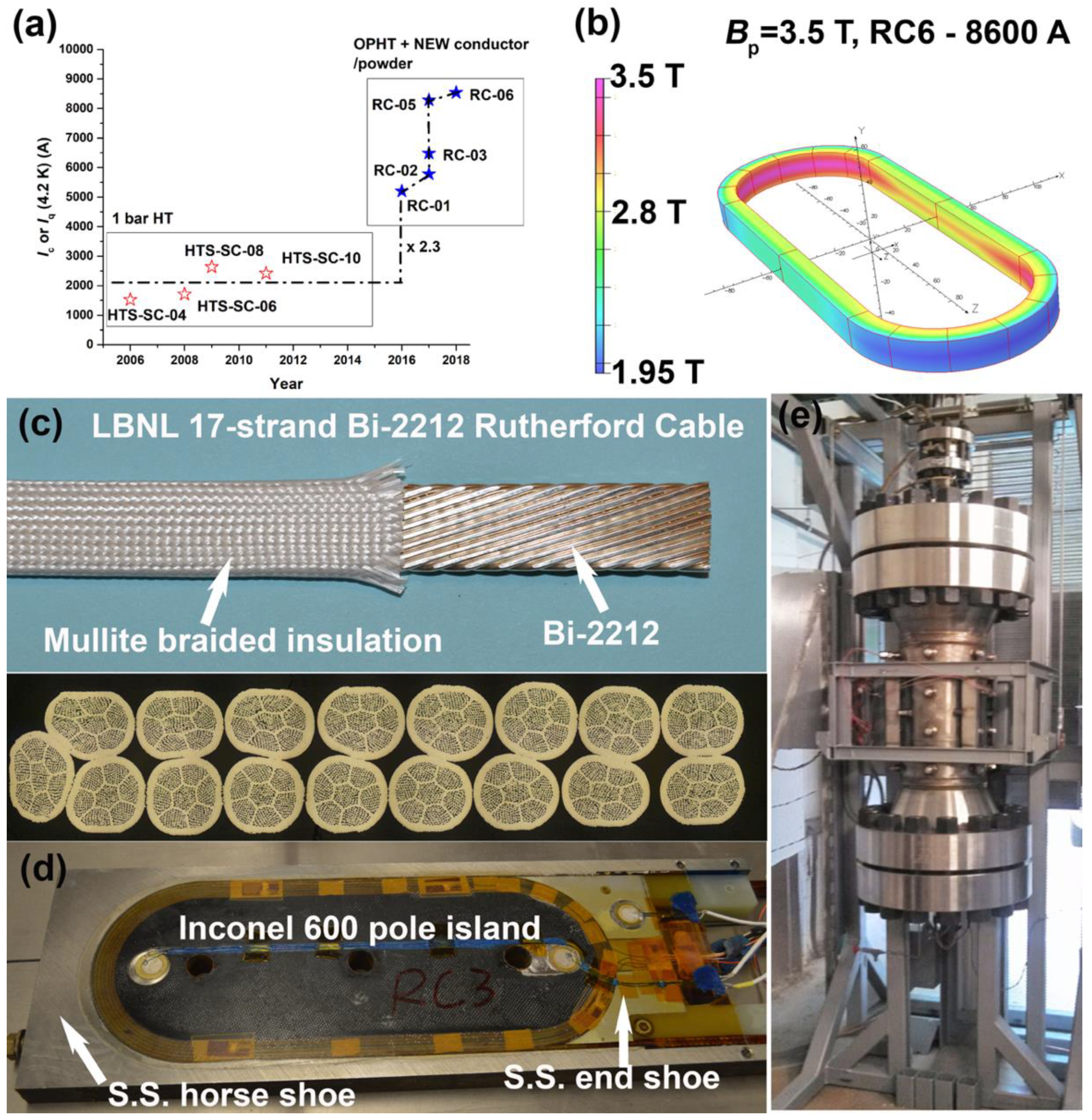
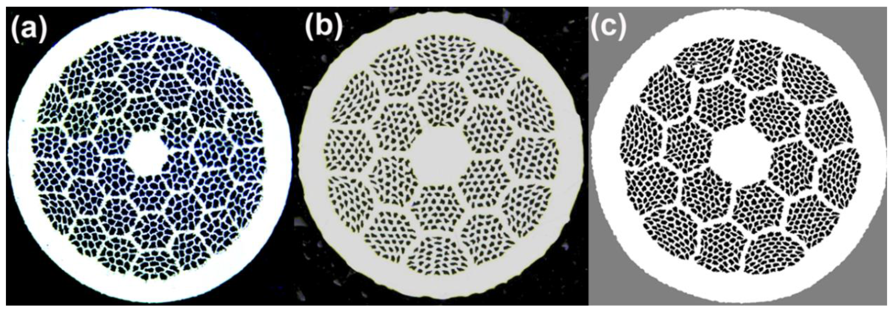
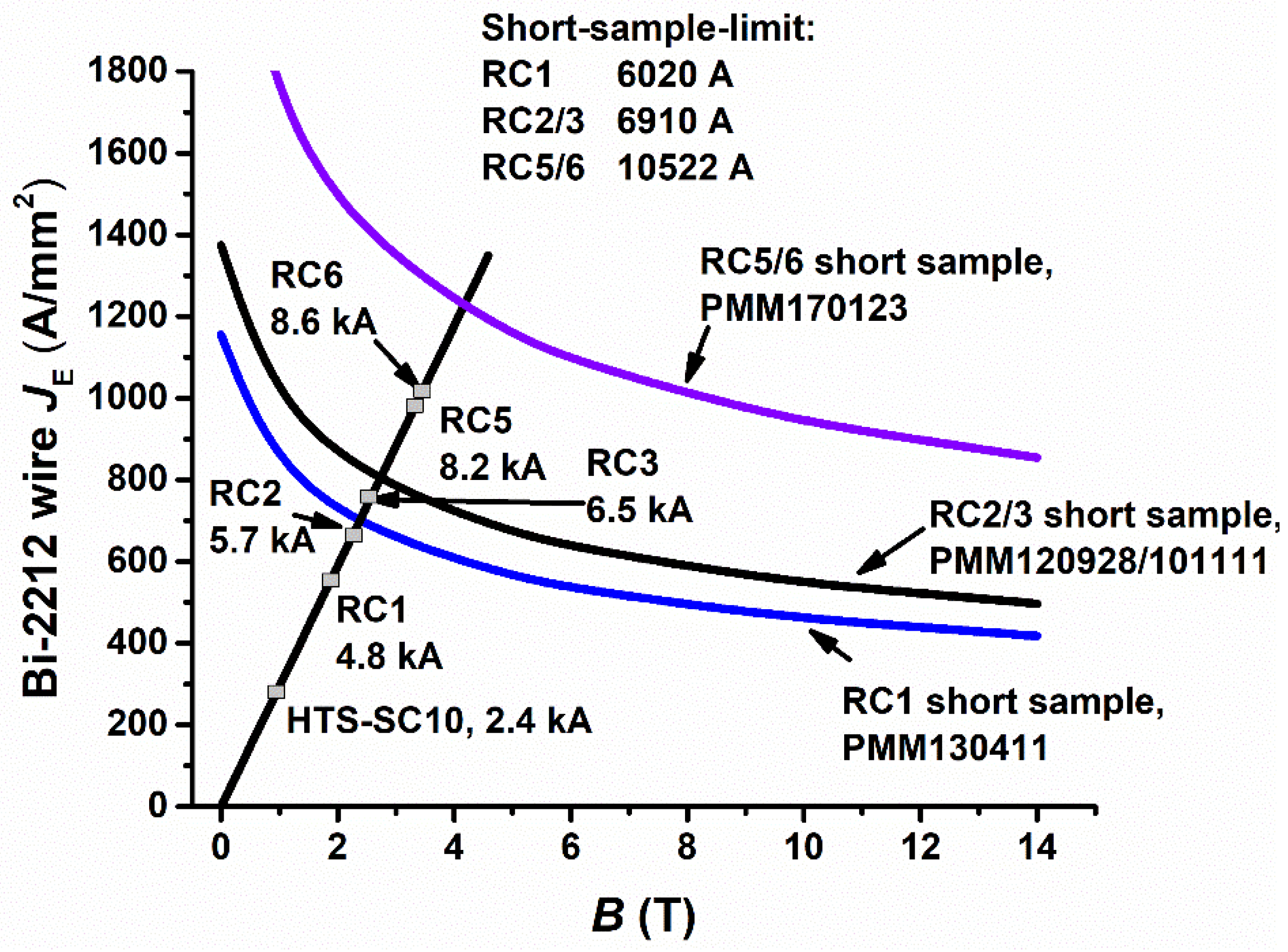
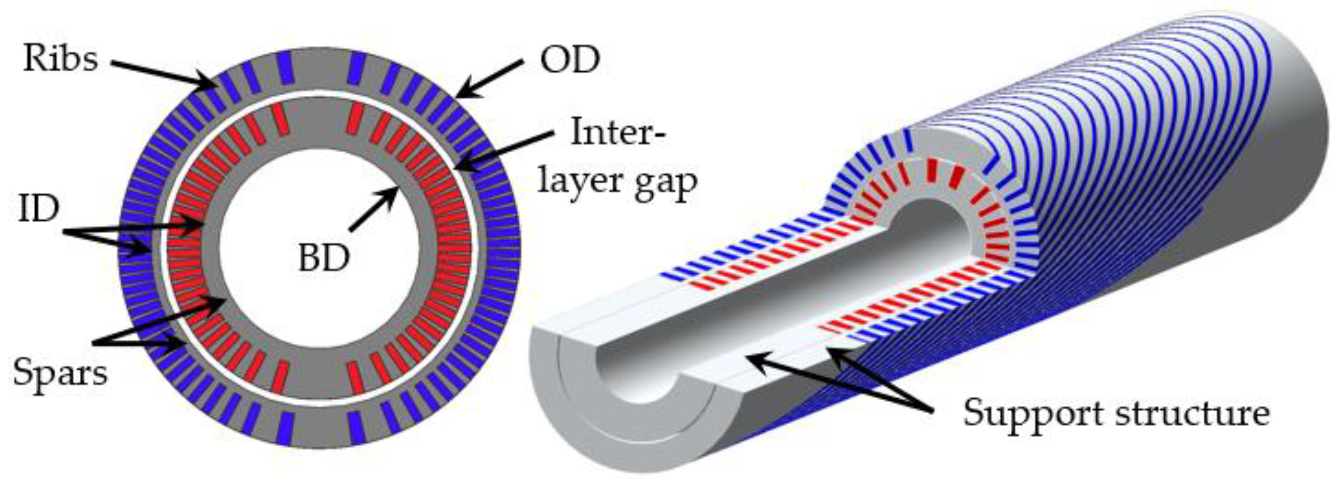
Table 1.
Summary of Bi-2212 CCT coils fabricated at LBNL. “654” means the 654-aluminum bronze whereas “954” refers to the 954-aluminum bronze. The central core of the “6 + 1” cable used for BIN2IL is a Bi-2212 strand as well. The 50 bar OPHT was performed at NHMFL. The BIN2IL quench current data is a courtesy of Dr. Xiaorong Wang of LBNL and the field quality data of BIN5aOL is a courtesy of Dr. Xiaorong Wang of LBNL and Dr. Cory Myers of the Ohio State University.
| Coil (Year) | Conductor | Mandrel | Insulation | Heat Treatment | Performance |
|---|---|---|---|---|---|
| BIN1 (2014) | Single strand | Inconel 600 | Mullite sleeves | 1 bar HT | Extensive leakage |
| BIN2IL (2014) | 6 + 1 round cable | 654 | Mullite sleeves | 1 bar HT | Iq~1.477 kA at 4.3 K, Peak field Bp on conductor = 0.48 T, B1 = 0.29 T in the bore. Significant deformation after reaction. |
| BIN3 | - | - | - | - | Not manufactured. |
| BIN4 (2017) | 9-strand Rutherford cable | 954 | Mullite sleeves | - | Electrically shorted to mandrel after winding. Not reacted. |
| BIN5aOL (2018) | Same as above | 954 | TiO2 slurry on mullite sleeves | OPHT | Bore diameter = 51.5 mm. SSL = 6.48 kA. Iq~4.02 kA at 4.2 K, Bp on conductor = 1.3 T, B1 = 0.71 T in the bore, b3 = 1000 units and about 30 units at r = 13 mm due to persistent currents at I = 1 kA. Small deformation after reaction. Epoxy impregnated. |
| BIN5bOL (2018) | Same as above | 954 | TiO2 slurry on mullite sleeve | OPHT with Inconel 600 strongback | Transferred to a Bluestone 3D-printed mandrel after reaction. Iq~3.1 kA at 4.2 K. |
| BIN5c (2020) | Same as above | 954 | TiO2 slurry on cable, and on mullite sleeve | OPHT | In fabrication. SSL = 5.85 kA. Bbore = 2.4 T. |
| BIN6 (2021) | 17-strand Rutherford cable | 954 | Same as above | OPHT | In design. SSL = 9 kA, Bbore = 5 T. Bore = 50 mm. OD = 100 mm. |
© 2020 by the authors. Licensee MDPI, Basel, Switzerland. This article is an open access article distributed under the terms and conditions of the Creative Commons Attribution (CC BY) license (http://creativecommons.org/licenses/by/4.0/).
Share and Cite
MDPI and ACS Style
Shen, T.; Garcia Fajardo, L. Superconducting Accelerator Magnets Based on High-Temperature Superconducting Bi-2212 Round Wires. Instruments 2020, 4, 17. https://0-doi-org.brum.beds.ac.uk/10.3390/instruments4020017
AMA Style
Shen T, Garcia Fajardo L. Superconducting Accelerator Magnets Based on High-Temperature Superconducting Bi-2212 Round Wires. Instruments. 2020; 4(2):17. https://0-doi-org.brum.beds.ac.uk/10.3390/instruments4020017
Chicago/Turabian StyleShen, Tengming, and Laura Garcia Fajardo. 2020. "Superconducting Accelerator Magnets Based on High-Temperature Superconducting Bi-2212 Round Wires" Instruments 4, no. 2: 17. https://0-doi-org.brum.beds.ac.uk/10.3390/instruments4020017