Design and Physical Prototyping of a Novel Braking System for a Helicopter Rotor


Electrical Energy Management Research Group, Faculty of Engineering, University of Bristol, Bristol BS8 1TR, UK
*
Author to whom correspondence should be addressed.
Designs 2019, 3(3), 40; https://0-doi-org.brum.beds.ac.uk/10.3390/designs3030040
Submission received: 5 July 2019
/
Revised: 24 July 2019
/
Accepted: 25 July 2019
/
Published: 28 July 2019
Abstract
:The aim of this paper was to demonstrate the improved functionality and performance of an electromechanical brake for a helicopter main rotor, which to date has been hydraulically actuated using a disc brake and caliper arrangement. Increasingly, designers seek higher performing solutions to traditional problems through the integration of modern actuation and control strategies. This electromechanical device is required to constrain the helicopter tail rotor shaft protruding from the main rotor gearbox to allow safe taxiing and storage of the helicopter. A systematic and rigorous design methodology was used to converge on an effective solution which satisfied a very demanding specification. The design was further detailed and optimized, leading to the development of a prototype at a high technology readiness level that was tested within a bespoke rig, simulating the torque requirements found on a helicopter main rotor using the torque and position control. The design was shown to meet the required holding torque whilst providing additional functionality of continuous holding capability and meeting the challenging volumetric constraints.
1. Introduction
In recent years, the complexity of products and devices has increased substantially to meet the increasing demands of customers, to open up new opportunities and increase functionality and performance. Typically, there is a requirement to integrate actuation and control with more traditional mechanisms and devices in order to meet these needs. Modern electromechanical systems have great potential to deliver reliable, compact, low-mass, high-efficiency, power-dense, low-acoustic noise and low-maintenance solutions. In response to performance demands in the aircraft industry, the process of developing a succession of increasingly More Electric Aircraft (MEA) is topical [1] and auxiliary functions previously powered hydraulically or pneumatically are being replaced by electrically powered systems. As a result, more power dense machines will be needed to serve increased power requirements in these mass-critical applications whilst also having a considerable advantage over other prime movers when considering environmental and economic factors.
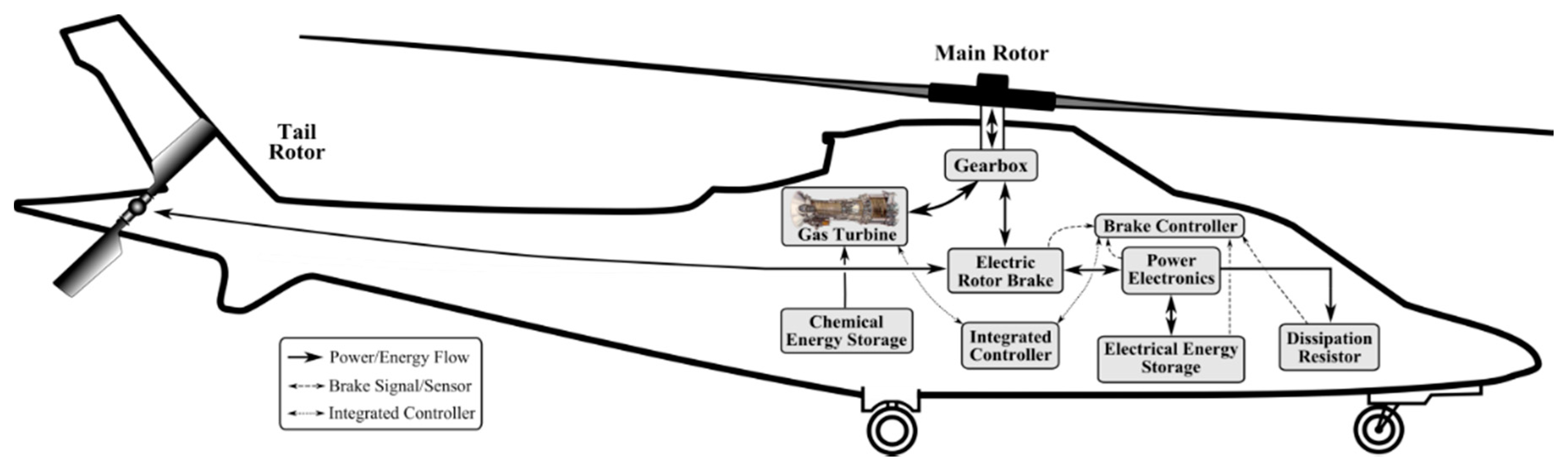
Such a system is an electromechanical brake designed for helicopters. This device was designed to operate in series with a regenerative brake system. The project context and objectives can be found in [2]. Currently, hydraulically actuated brake calliper pads with a steel disc connected to the main gearbox are used to slow down the rotor once on the ground. Disc brake systems suffer from inhomogenous heating and hydraulic systems are generally bulky, complex and prone to leakage [3]. A new approach is to provide helicopters with a regenerative electrical braking capability in place of the traditional hydraulic system further down the transmission shaft to the tail rotor, which is powered from a main gearbox take off shaft to also provide a ‘stop and hold’ brake. The anticipated systematic integration of the braking system is shown graphically in Figure 1, where the Electric Brake System presents both the static and dynamic elements.
Having brought the rotor to a stop using the regenerative aspect, the brake locks in place, preventing any further motion, and allowing all electric braking systems to be powered down, which is vital to allow taxiing of the vehicle in a safe manner. No dynamic braking capability is required from this brake. Electrically actuated brakes are already being developed for cars [4,5,6,7]. Solenoids and some mechanical advantage system are typically utilised, whilst still retaining the more traditional disc brake arrangement. The available working envelopes on rotorcraft do not allow a disc brake and regenerative brake together, therefore, there is a desire to move away from disc brakes altogether. Mott [8] shows that a circumferentially contacting electrically actuated brake is viable, although the braking torques generated are insufficient on a rotorcraft platform, and there is no locking mechanism when power is off.
This paper describes the full design process, including details of the concept generation and evaluation phases to identify the solution with the greatest potential, detailed numerical analysis of the solution, and experimental validation demonstrating the functionality of the selected brake design against the specification. Finally, the scalability and technical readiness of the solution for future applications is considered.
2. Design Development
2.1. Product Design Specification (PDS)
The PDS was developed consisting of both quantitative and qualitative requirements. These were a combination of physics-based performance measures, along with more subjective traits associated with the selected design. In addition, the design and testing of such safety critical systems was subject to certification requirements, as set out in CS-29 [9] for European manufacturers. The important elements of the specification are shown in Table 1.
2.2. Concept Generation
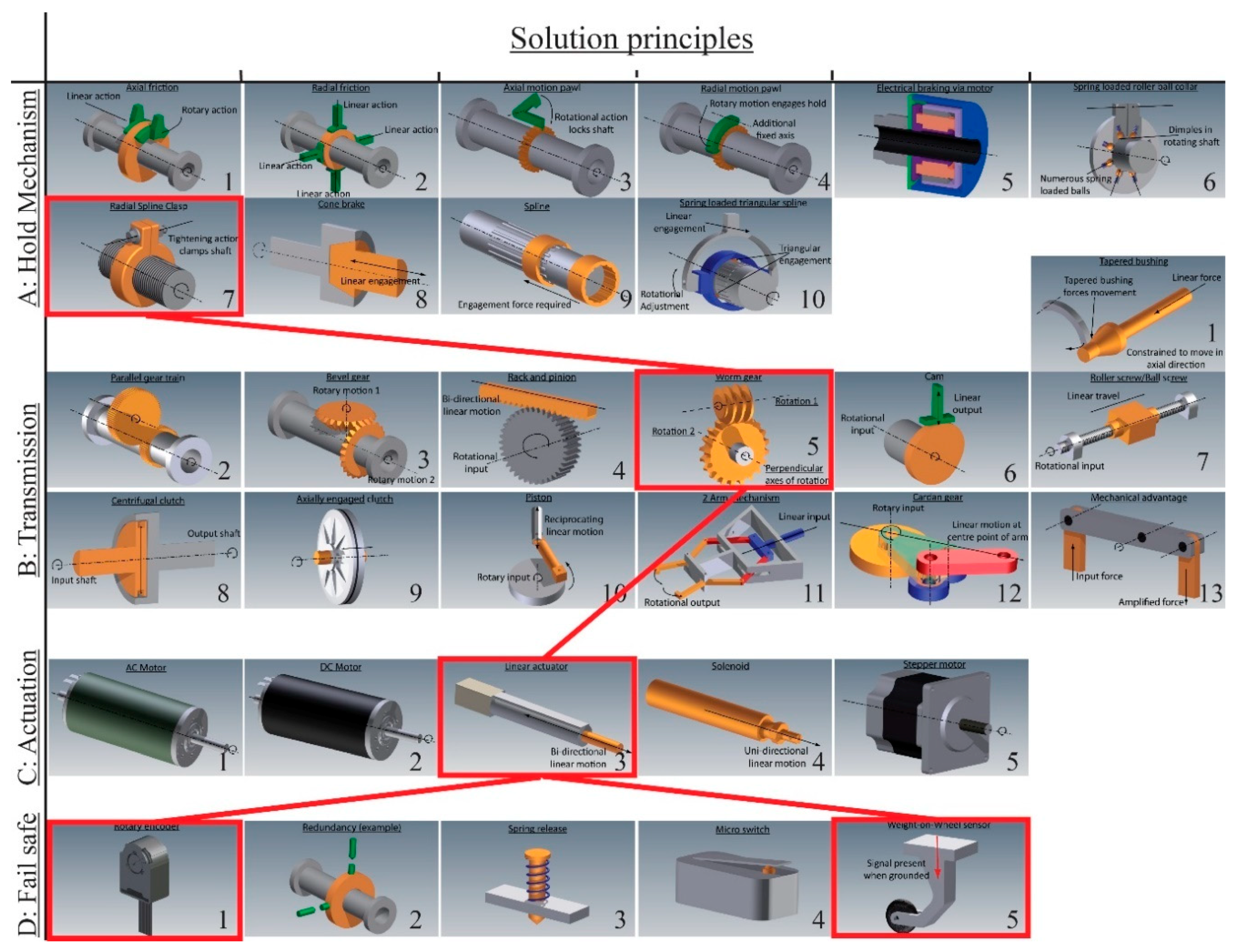
In an attempt to establish the optimal solution based on the requirements stated in the PDS, efforts were taken to avoid any pre-formed biases towards the anticipated best solution. To help with this, a morphological approach was used for concept generation that split the brake system into various sub-functions, treating all solutions equally [10]. The key sub-functions were identified as hold mechanism, transmission, actuation and fail safes. Synthesis of these sub-functions led to complete concept ideas. Numerous solutions for each sub-function were identified. The full range is graphically shown in Figure A1 (Appendix A). These were generated through brain storming exercises, as well as additional literature sources [11]. The design synthesis of the various sub-functions enabled the generation of numerous and varied concept solutions. In a study by Fricke, attempts were made to identify the ideal number of concept designs to evaluate [12]. A specific number was never specified, although the guidance was that designers should select a ‘moderate’ number of concepts so as to enable them to ‘explore the solution space without becoming bogged down in excessive evaluation’ [13]. Utilising the morphological approach led to the selection of nine potential concepts to be taken forward to the evaluation phase to match this strategy.
2.3. Concept Evaluation and Selection
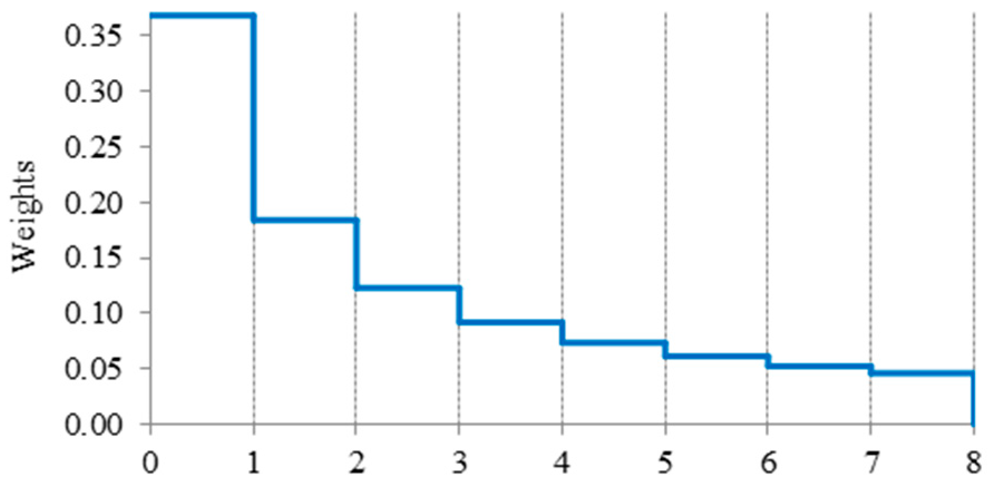
The performance evaluation was categorised into criteria, as shown in Table 2. These criteria were selected to encompass the important issues detailed in the PDS. Eight criteria were derived, in keeping with recommendations made in the literature [14]. Within each of these categories, numerous scoring criteria were utilised in order to quantify each of the nine concept solutions generated. For each scoring criteria, solutions were awarded a grade between 1 and 5, with 5 being the highest (i.e., best performance) and 1 being the lowest (i.e., poor performance). As each performance criteria contained a varying number of performance measures, each criterion was normalised so that the overall score had a maximum value of 1, irrespective of the number of measures. Furthermore, as the various categories did not carry equal importance when considering overall concept solutions, additional weightings were utilised in order to select the solution with the greatest potential based on anticipated industrial application preferences. The criteria are arranged in the selected ranking in Table 2 based on guidance from stakeholders. The weighting strategy utilised degradation from the initial highest weighting, whereby the subsequent weightings were proportions of the initial value. This means that the second weighting was worth half the first, the third weighting was worth a third of the first and so on, as shown in Figure 2.
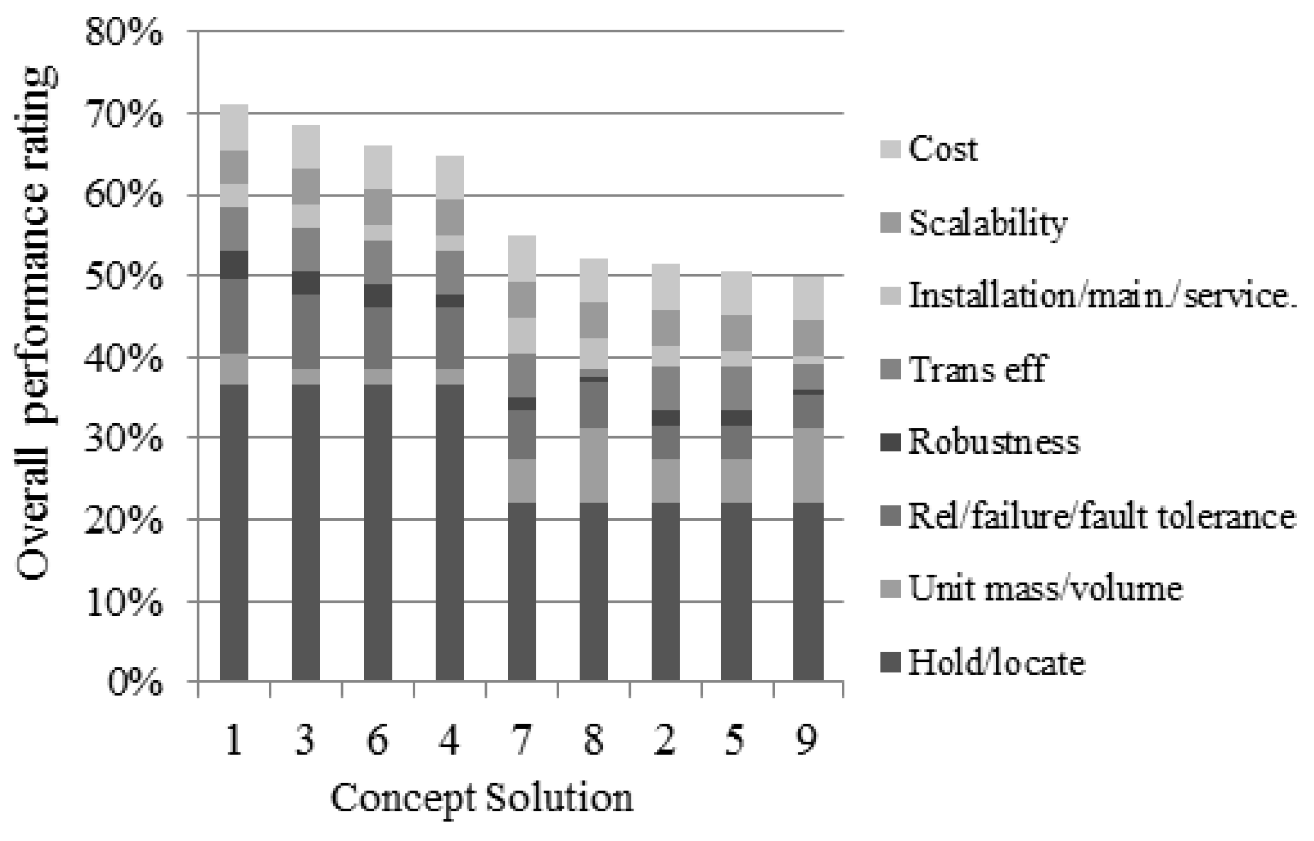
The outcome of the concept evaluation phase is shown in Figure 3, where the highest ranked criteria typically constitute the greatest contribution to the overall score (i.e., the lowest sections relating to ‘hold/locate’ criteria). The leading solution was concept 1 (71% satisfaction of the criteria). The concept utilises a worm gear to drive a threaded clamp, which pushes and pulls the radial arms together. This radial clamping force translates into the holding torque about the shaft to which it engages through friction pads. As the concept utilises a friction-based holding mechanism, this allows a numerical analysis to be completed for the concept solution, potentially improving the performance, as parameters such as component geometry, required loading forces, and material selection were set according to the original specification. A CAD sketch of this more embodied concept can be seen in Figure 4.
3. Modelling and Simulation
3.1. Modelling
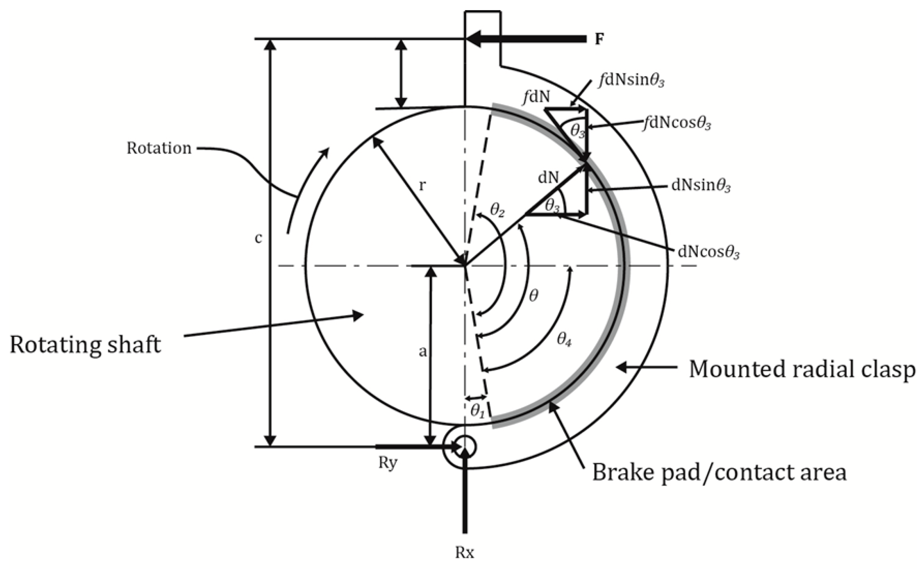
Numerical analysis was used to develop a greater understanding of the concept prior to any product manufacture. Focusing resources at this early stage of product development minimised the risk in the final concept selection and helped reduce the need for multiple experimental testing platforms. A major factor was the required engagement force associated with the design, which engaged the radial arms that subsequently applied the required holding torque of 400 Nm. This engagement force is shown in Figure 5, labelled F. As a primary design intent was to minimise mass, establishing which solutions required the least amount of engagement force to achieve the holding torque whilst continually considering the design complexity of the solution was paramount. The numerical model helped establish key geometric parameters and acted as a guide to develop initial testing platform designs. Figure 5 demonstrates the forces experienced by one side of the clasp arrangement. In this case the engagement force is modelled as point load F (N), which subsequently results in a pressure between the shaft and the outer clasping arm.
It has been shown [13] that the pressure distribution can be modelled according to the following equation:
where pa is the largest pressure on the brake shoe, θa is the angle from the hinge pin where the maximum pressure acts, and θ is the angle of interest. When a friction clamp is large (i.e., contact angle > 90°), the maximum pressure is found to occur at θa = 90° from the hinge point [15]. As , Equation (1) is simplified to:
In Figure 5, r represents the radius of the shaft (m), a is the distance from the hinge point to the centre of the rotating shaft (m), and c the distance from the hinge point to the point at which the engagement force is applied (m). θ1 is the angle from the hinge point to the start of the braking surface and θ2 is the angle from the hinge point to the end of the braking surface. θ3 is the angle of the point force under consideration from the horizontal axis and can be calculated as
The forces of interest are the engagement force F (N), the differential normal force dN (N) and the pin reaction forces Rx and Ry (N). The coefficient of friction of the contacting surfaces is f. Combining localised pressure and normal forces, an expression for the torque applied, Ti, by the radial clasp can be formed:
which can be rearranged to make pa the subject, used in subsequent analysis:
The torque, T, was given subscript i, as the radial clasp had two sides to the arrangement and the forces shown by Equation (4) only represent one side of the brake arrangement. The direction of the motion relative to the braking surface had an effect on the forces and the subsequent holding torque. In a symmetrical braking arrangement such as this, one side is found to be self-energising and as such, generates a greater amount of holding torque for the same engagement force. This is explained by considering the moment forces experienced by the clasping arrangement. Taking moments about the hinge point can establish the required engagement force F in order to balance the moments associated with the frictional and normal forces Mf and MN, respectively:
The actuation force, F, must be large enough to balance both moments:
If rotation occurs in the counter-clockwise direction, the sign of the frictional term in Equation (8) is reversed, hence becoming:
This relationship results in this side of the clasp being described as ‘self-energising’. The frictional moment actually assists the engagement force. The final forces established are reaction forces at the hinge pin. These are of use in order to determine suitable component sizes, such as the clasp arm thickness and the hinge pin diameter. Resolving forces in the x-direction (acting from hinge point to centre of shaft) and y-direction (acting hinge point into the clasp arm) and substituting for dN and θ4 = 90° leads to:
These are true during clockwise rotation and are adjusted as described above when considering the self-energising side.
3.2. Simulation
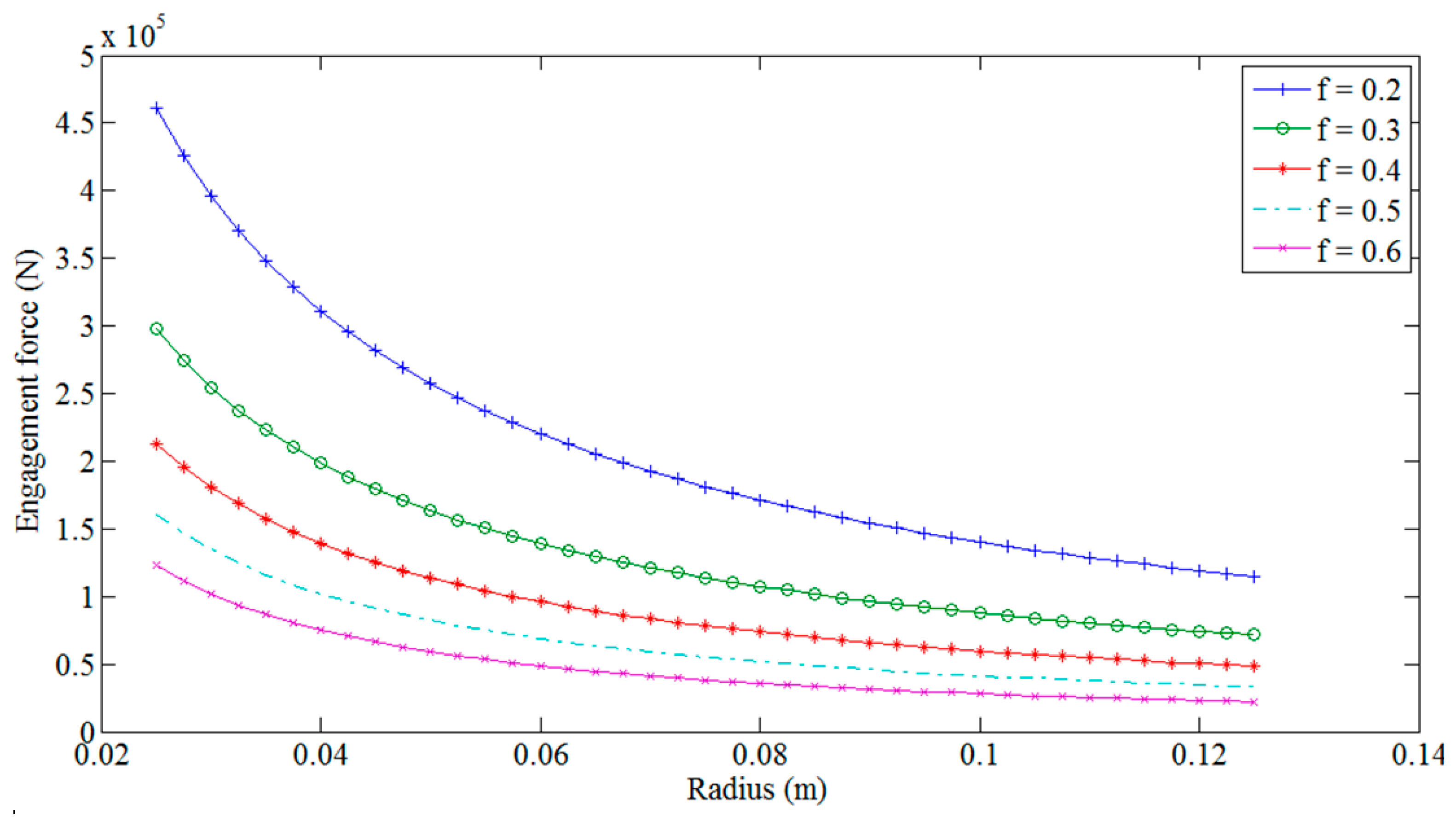
As the system specification has specific mass and volumetric constraints, establishing a feasible size for the brake is vital. The major geometric dimension was identified as the radius of the internal shaft, r (m). The other term which the design team had control over was the coefficient of friction between the surfaces, f. The analysis demonstrated the implications of variations in these values, providing the resulting forces the system would need to generate whilst remaining structurally sound. Due to the difference in forces and pressures experienced on either side of the clasp due to the self-energising nature of the counter-clockwise motion, an iterative approach was incorporated within a MATLAB script used in the sensitivity analysis so that the combination of the torques from the right and left hand sides summated to the required 400 nm. This adaptive approach ensured that values for required engagement forces and experienced pin reaction forces and pressures were representative. The process was completed over a range of coefficient of friction values based on documented literature [16,17] and shaft radii within the limits were imposed by the specification (i.e., outer diameter of 250 mm). The results shown in Figure 6 quantify the required engagement force showing variations in radius and f values, confirming that they are highest when using a small radius and a low coefficient of friction. The aim was therefore to determine the size and contact material (and hence coefficient of friction) to use, considering the trade-off in brake size versus the required actuation.
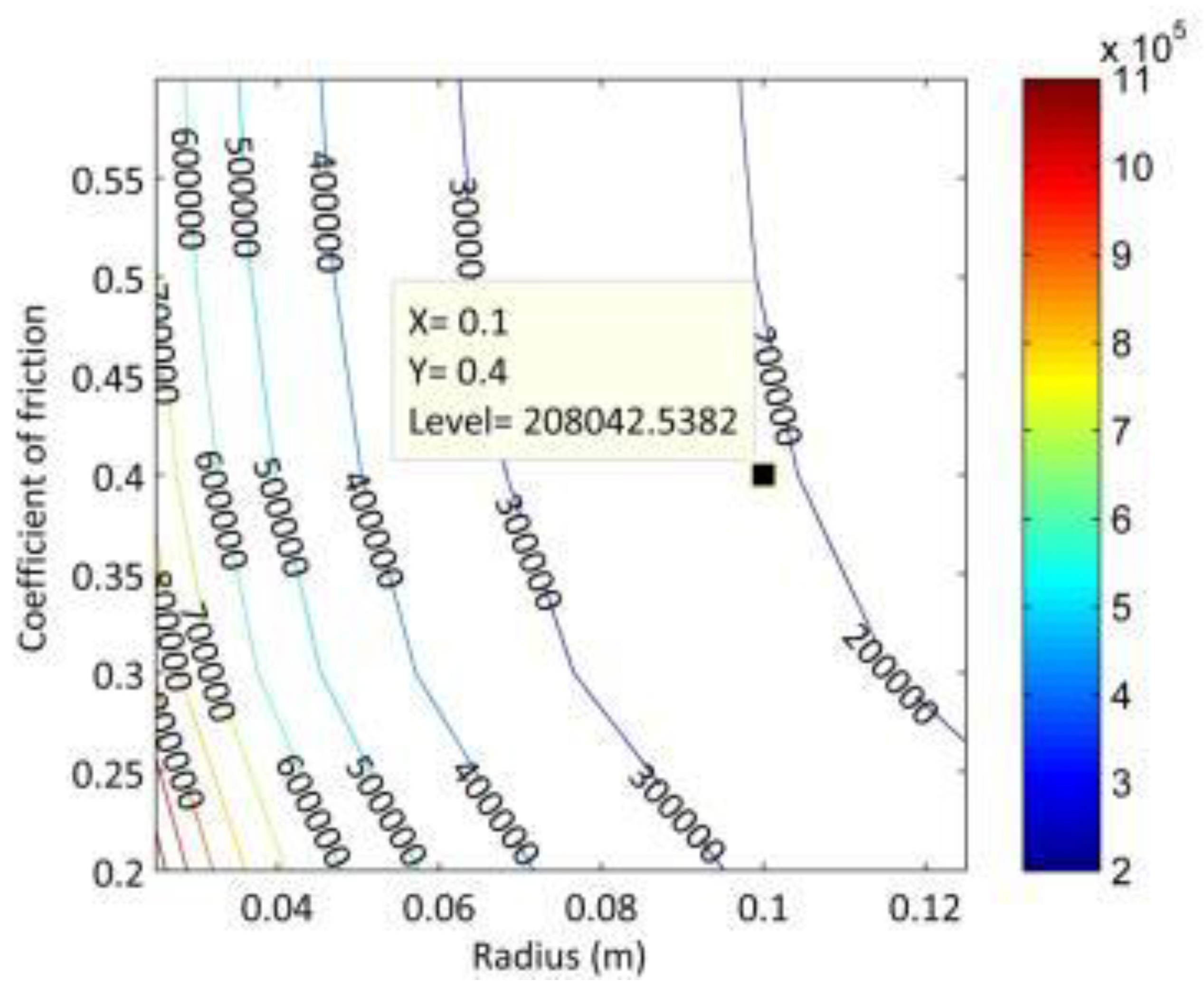
Again, due to the self-energising aspect of the left-hand side clasp, this leads to greater forces within the pin reaction. As the brake could, in theory, need to resist a torque trying to turn in either direction, the larger value was always used when designing the system (i.e., if the brake needed to operate in the opposite direction, the right hand side clasp would become the self-energising side). The pin reaction forces helped establish key geometric parameters based on the calculated values, such as required pin dimensions and material for it to withstand the anticipated shear loads. The resultant reaction forces for the left clasp are shown in Figure 7. A point at r = 0.1 m and f = 0.4 is highlighted.
From the initial numerical modelling, it is apparent that maximising the inner shaft dimension, i.e., the diameter of the rotating rotor shaft section to which the friction brake engages, is paramount in achieving an arrangement that requires minimal engagement force to achieve the required holding torque, as shown in Figure 6. Additionally, the coefficient of friction plays a crucial role in helping minimise the overall size, subsequently driving the mass of the system down. However, the majority of data available for friction materials is based on high temperature and/or dynamic loading. Hence static testing of the potential materials was required to validate the achievable values.
4. Experimental Measurement of Friction
4.1. Test Materials
There are numerous brake material compositions on the market, however many structures lack detailed material descriptions, as these are developed by individual companies. A detailed summary of the typical components of brake materials found in the automotive industry is given in [18]. Although these components are specific to the automotive industry, they help demonstrate the variations present in brake pad compositions. Several different fireproof materials were selected as brake pads for the initial experimental testing, a semi-metallic material and three non-asbestos organic materials. For the semi-metallic sample, a material from Trimat Friction Solutions was selected, specifically Trimat GBC. This was a semi-flexible asbestos-free brake lining, manufactured from a solid woven fabric of both natural and man-made yarns with a brass wire inclusion. The first of the organic materials was again from Trimat Friction solutions, specifically Trimat MR2215. Compared with the semi-metallic brake material, the specified dynamic coefficient of friction was lower, at 0.39 compared with 0.48 but this was anticipated to be lower than the actual static value achieved when completing bench tests. The second organic material was Trimat MR8728. The properties of this organic material compared to MR2215 were that this material had a greater wear rate, with 47 mm3/MJ compared to 22 mm3/MJ for MR8728 and MR2215, respectively.
4.2. Testing Platform
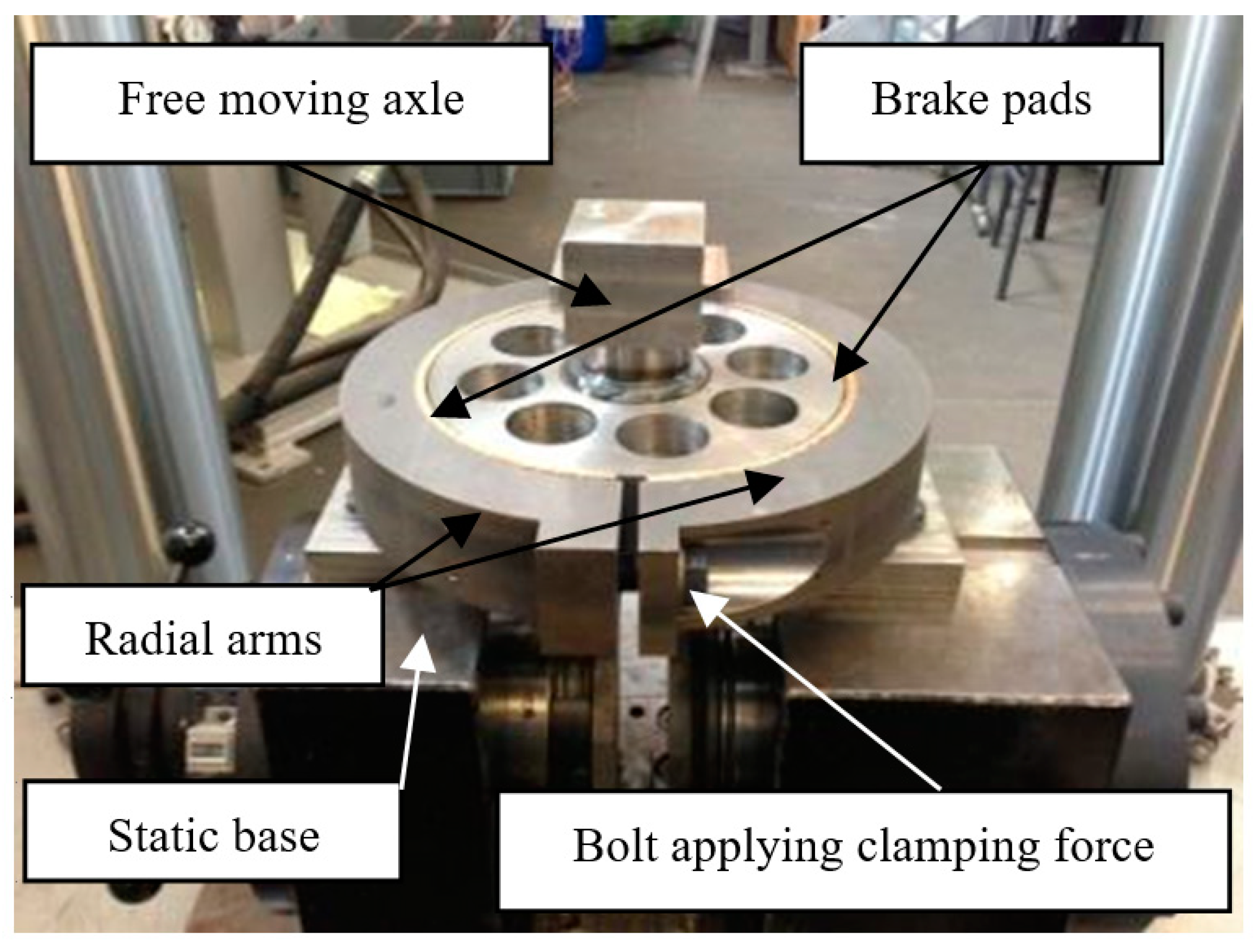
Ahead of developing the fully electromechanical system, bench tests were completed to identify the engagement forces required to achieve the specified holding torque of 400 nm and to quantitatively determine the achievable coefficients of friction for the various selected brake materials. The torque was generated by a Dartec Torsion loading platform (25 knm). This loading device can apply rotary motion to a test piece whilst monitoring the reactionary torque experienced in the system. The square section driver shown in Figure 8 is located in a plate attached to the Dartec machine in order to transmit loads. The developed platform replicated the arrangement shown in Figure 5, with the engagement force measured by a Bahco IZO-D-30 digital torque wrench. This testing platform is shown in Figure 8. This was converted to a known force by following the relationship shown in Equation (12) [11]:
where T is the engagement torque (nm), F is the associated engagement force (N), k is the nut factor and D is the nominal bolt diameter (m).
4.3. Results
Several different tests were carried out to develop an overall representation of the friction material performance:
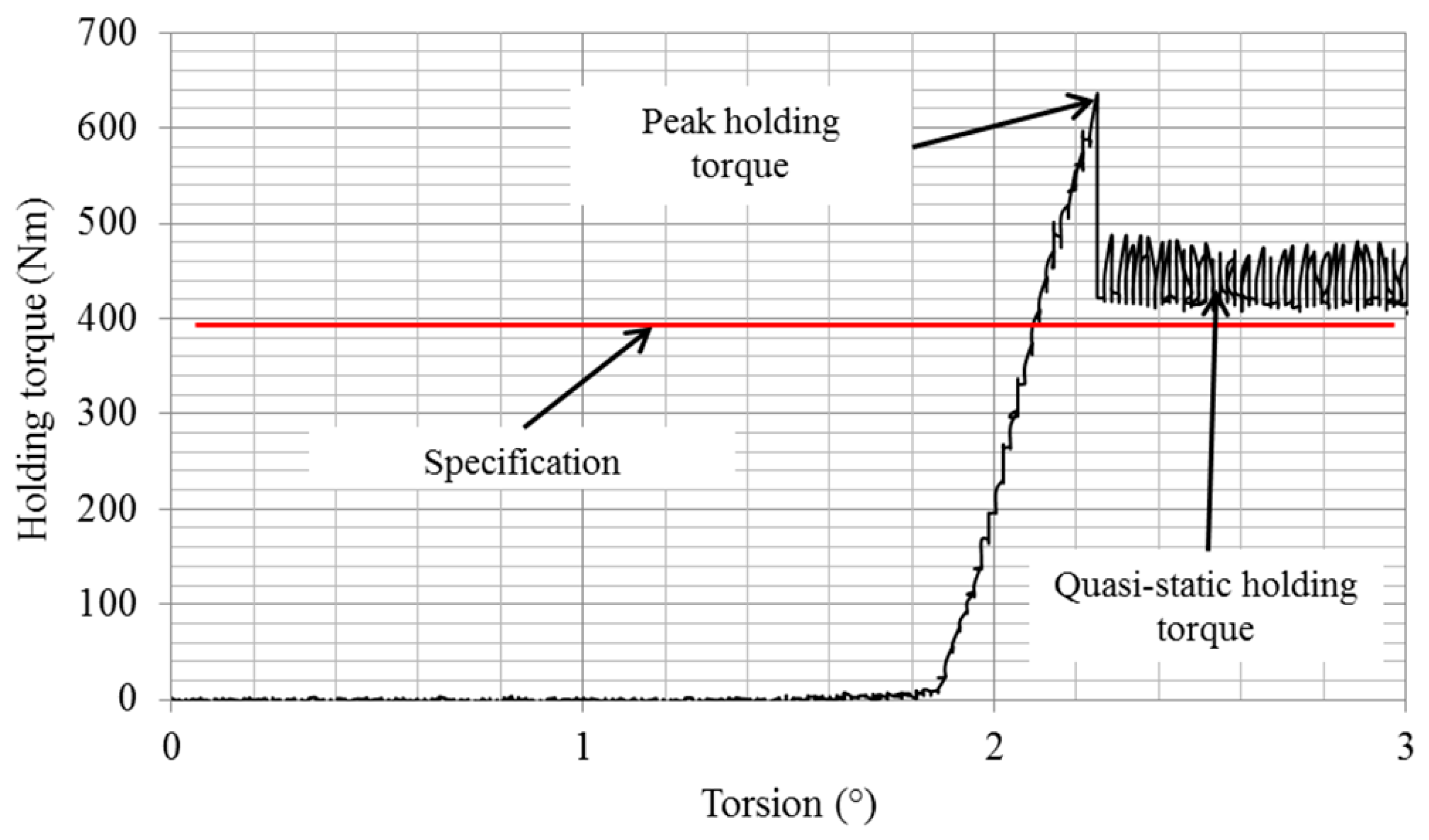
- Incremental loading increase (gradually increasing the engagement torque at suitable increments, noting the maximum torque before slip and the quasi static holding torque post slip, achieved for all materials);
- Variation of peak and quasi-static holding torques at different loading rates (i.e., the speed at which the Dartec machine rotated, increasing the rate of loading torque);
- Cyclic loading (once suitable engagement torques were found for each material to obtain the required 400 nm of holding torque, repeated loading up to this value and then released back down to just above zero was completed over several iterations to observe the behaviour of the clamping arrangement, loaded/unloaded up to the required torque in 20 s intervals).
An example data set recorded from the incremental tests is shown in Figure 9, with the 400 nm specification indicated by the red horizontal line. Note how a peak value was achieved at first point of slip before the holding torque stabilised at the quasi-static value.
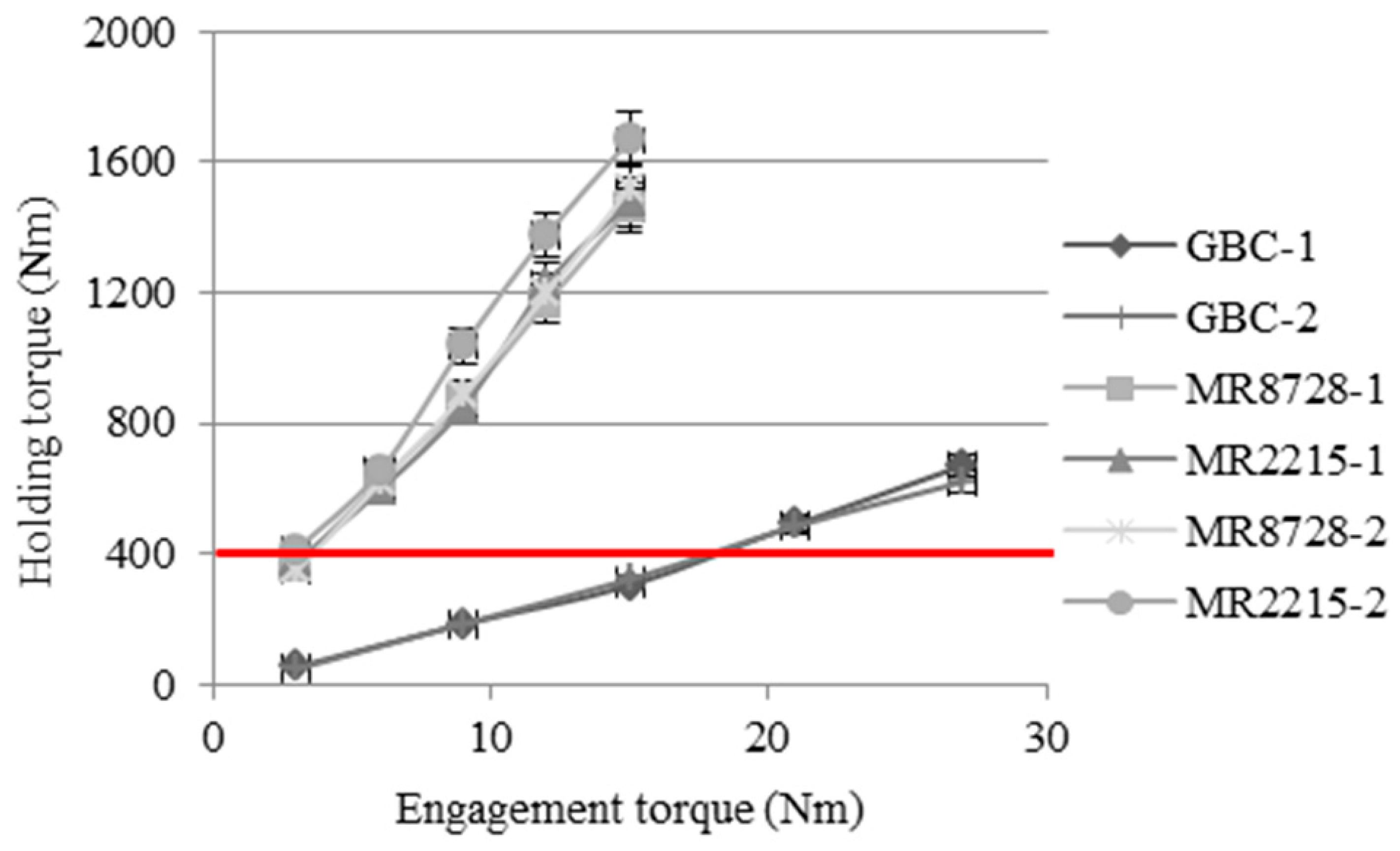
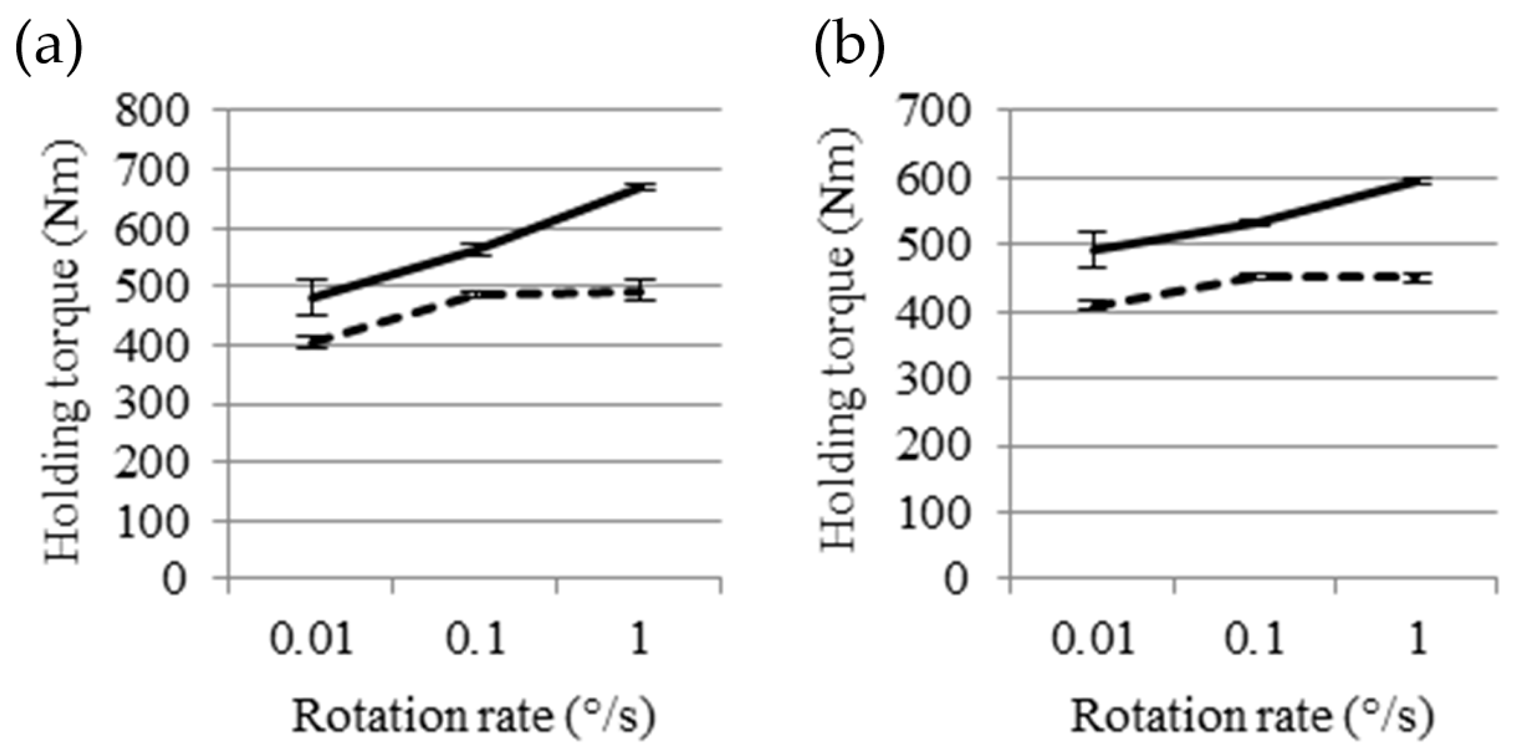
The overall results showing the holding torques achieved for various engagement torques for all Trimat materials are provided in Figure 10. Note that these results relate to quasi-static torques. It became evident that for the proposed application, the MR2215 and MR8728 outperformed the GBC material. Testing of each material was repeated with various loading rates, although limitations of the Dartec platform meant that the maximum rotation rate was limited to 1°/s. The general trend for the materials tested was that the peak torque increased with the rotation rate, whereas the quasi-static torque plateaued. This is shown for the MR2215 and MR8728 materials in Figure 11.
Figure 12 shows that all three Trimat materials are capable of withstanding cyclic loading above 400 nm with feasible engagement torques. The MR2215 material had the smallest angular deflection of approximately 0.19° with a loading cycle of 5 s. MR8728 experienced a slightly higher maximum, at 0.2°, followed by approximately 0.23° for the GBC material.
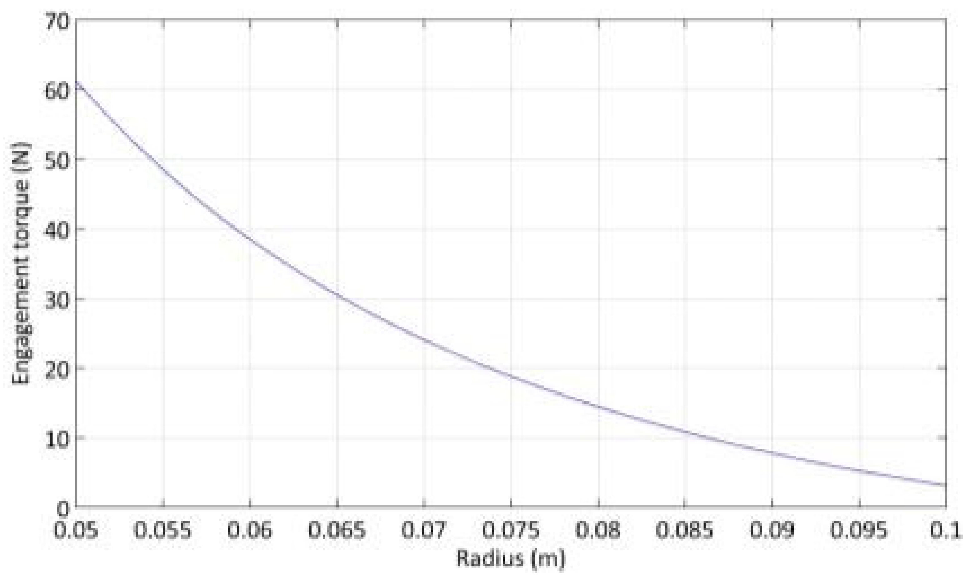
The value of the coefficient of friction within the numerical model was incrementally varied until the numerical and empirical models matched when considering an inner shaft diameter of 0.2 m, matching that used in the testing platform. From this, it was established that the coefficients of friction for the various brake materials were in the region of the following: 0.875 for GBC material and approximately 0.9 for MR8728 and MR2215. These are summarised in Table 3. By re-running the numerical model discussed earlier with 0.9 used as the coefficient of friction, a more accurate representation of the forces and associated torques that would be required if the inner shaft diameter was varied could be developed. This revised modelling of the forces can be seen in Figure 13, demonstrating that the engagement forces and torques are far greater for smaller shaft diameters.
5. Prototype Development
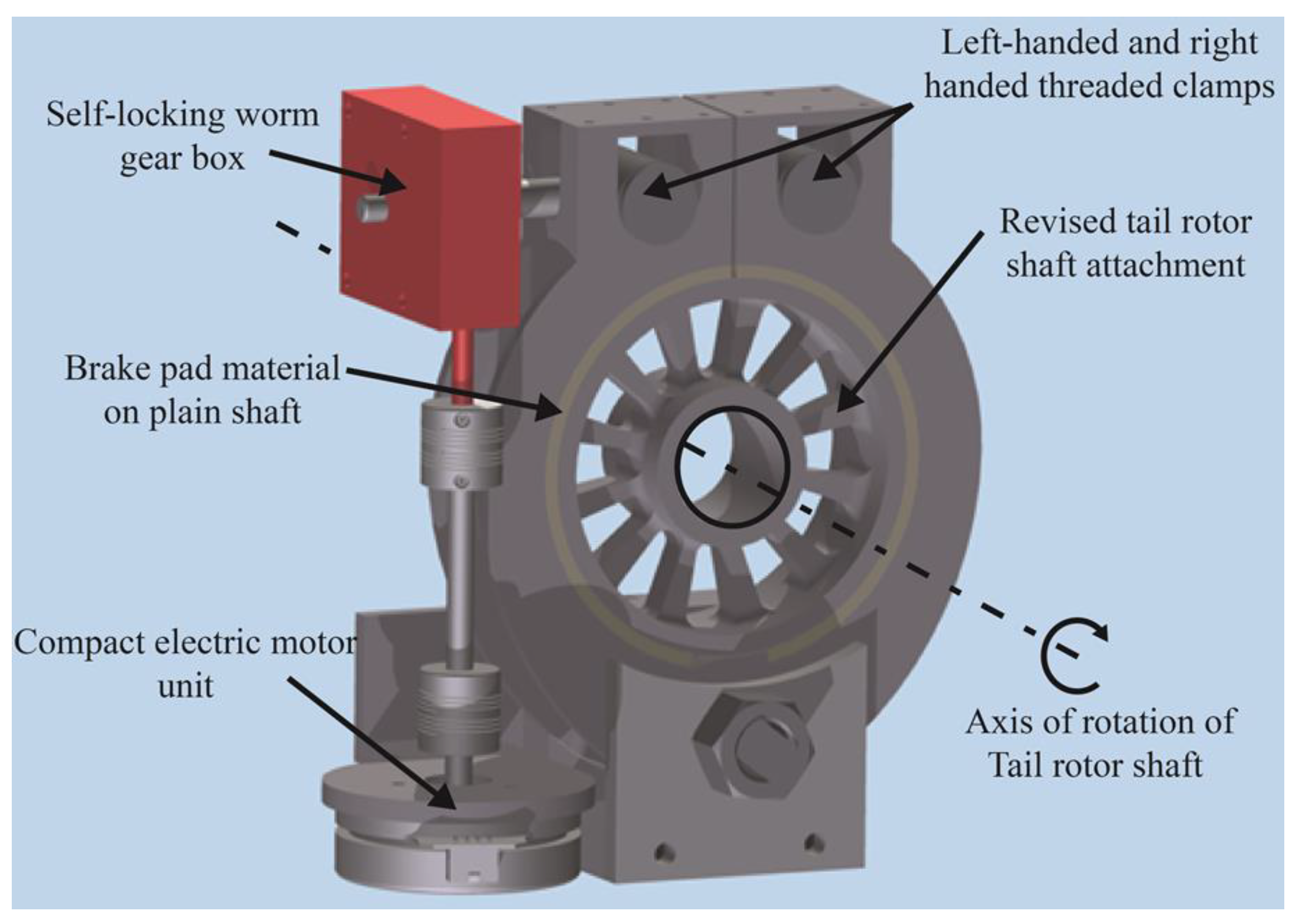
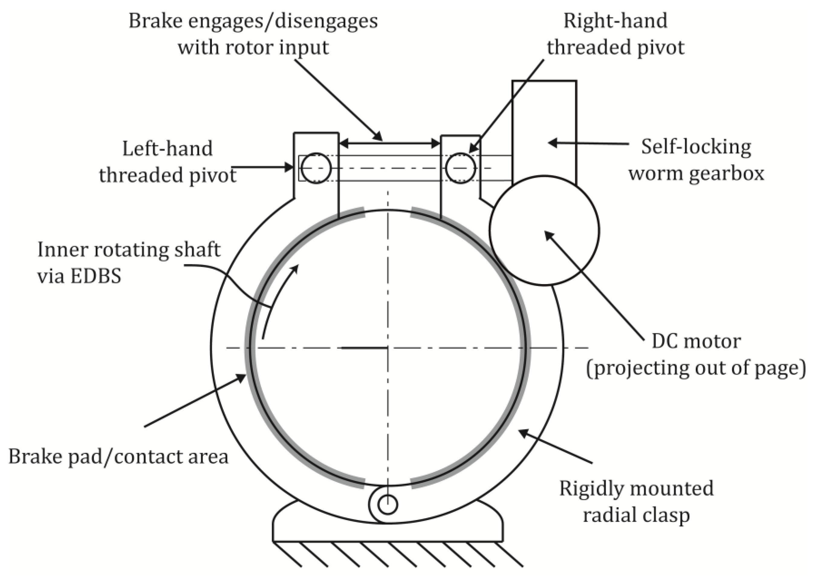
Following the concept design study, further work was completed to assess feasible transmission/actuation combinations for the radial clamping arrangement. The inline threaded clamp arrangement was selected to be taken forward based on the output of the concept analysis. The arrangement utilises a similar technique to the one used in the initial testing platform shown in Section 4.2, using a threaded bar to draw in the two radial arms, resulting in the clamping force. In this version, left-handed and right-handed threads were used so that rotation in a single direction resulted in opposing horizontal motion in the radial arms, either drawing them together or forcing them apart. A graphical representation of this arrangement is shown in Figure 14.
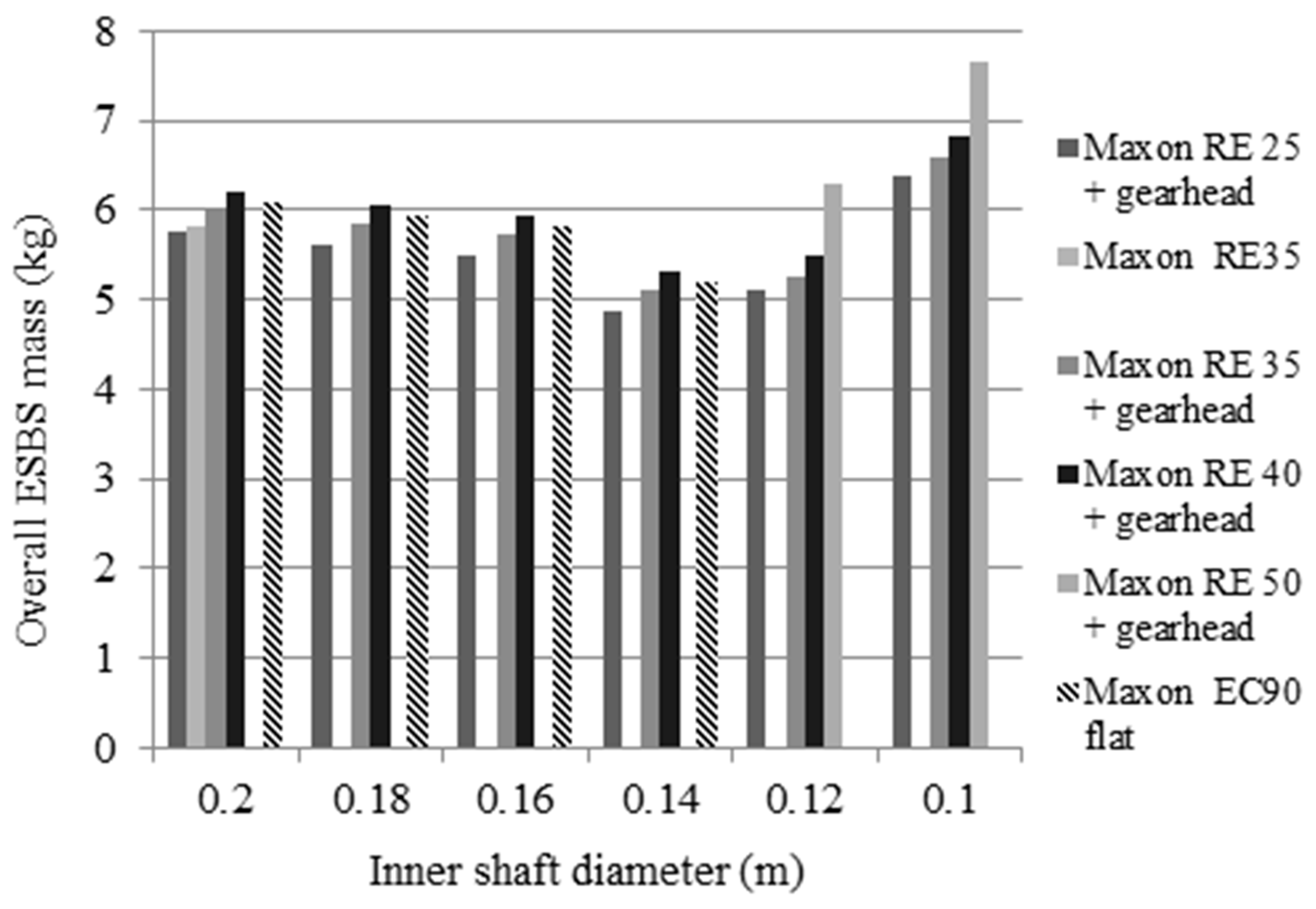
The design trade-off with this solution was determining the optimal inner diameter of the clamping surface to use whilst simultaneously considering the overall electromechanical brake mass. As the inner diameter was decreased, mechanical components decreased in size, but the required forces, and hence the electrical actuation, had to be increased. Numerous cases were considered, selecting a motor based on the specifications, which could supply the actuation force characterised in Figure 13. The findings of the trade study can be seen in Figure 15.
As the results for the range of inner diameters and associate masses were closely banded, additional aspects were taken into consideration for final selection. Firstly, maximising the inner diameter helped reduce the severity of the vertical misalignment of the threaded section following disengagement. Secondly, selecting a 0.2 m diameter correlated with the initial empirical testing, giving an added element of confidence in the design. Finally, the flat Maxon EC90 was selected due to its compact profile, assisting in realising a solution within the volumetric constraints.
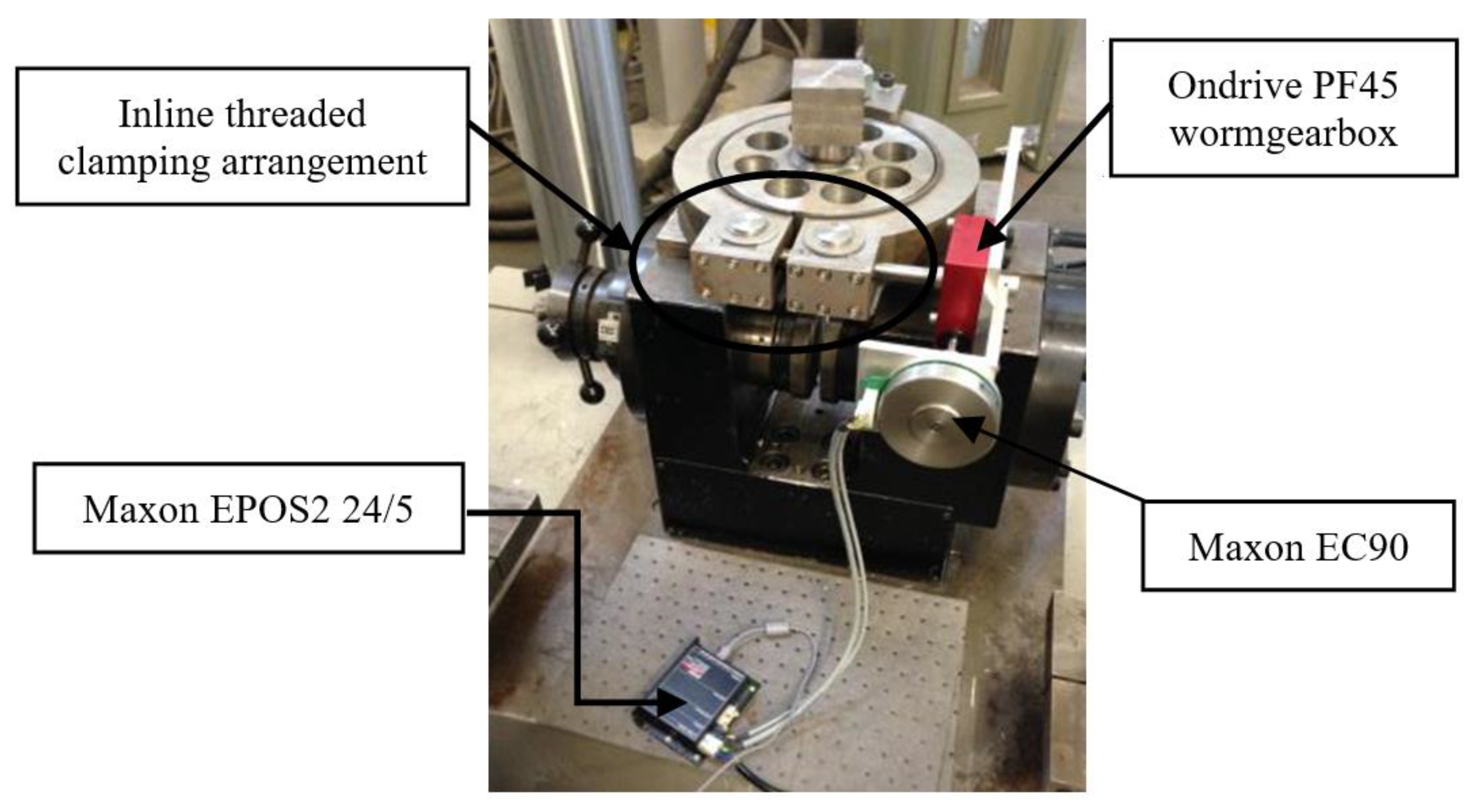
Figure 16 shows the constituent parts of the system prototyped which contains the full mechanical brake solution, the actuation with integrated sensors, and the motion controller. At this stage of testing, the brake was controlled via LabVIEW 2010 software, run from a desktop computer. Additionally, a Maxon EPOS2 24/5 motion controller was also used. The Maxon EC90 motor had an integrated hall sensor which was used to provide positional feedback. The EPOS unit uses an integrated PID control strategy. The gain values were determined by tuning the device with representative loads (i.e., connected to the gearbox). Once completed, the unit could be used to control the motor via position, velocity or current control modes. Using software drivers, LabVIEW could be used to communicate with the Maxon EPOS unit, subsequently controlling the Maxon EC90 motor, which was mounted to the Ondrive PF45 worm gearbox. By controlling the motor of the output of the gearbox, which is the inline threaded rod, it can open and close both arms of the radial clamping arrangement simultaneously.
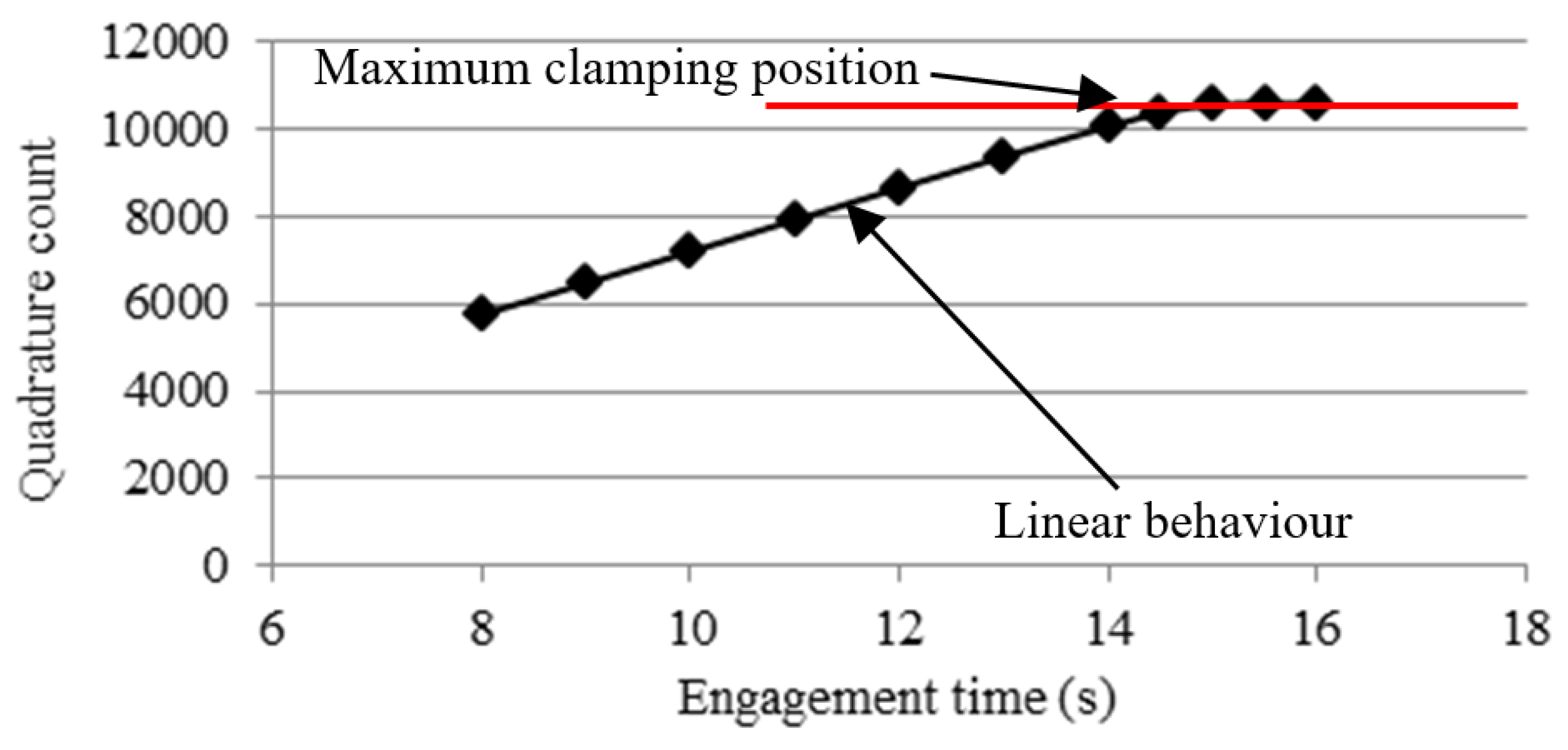
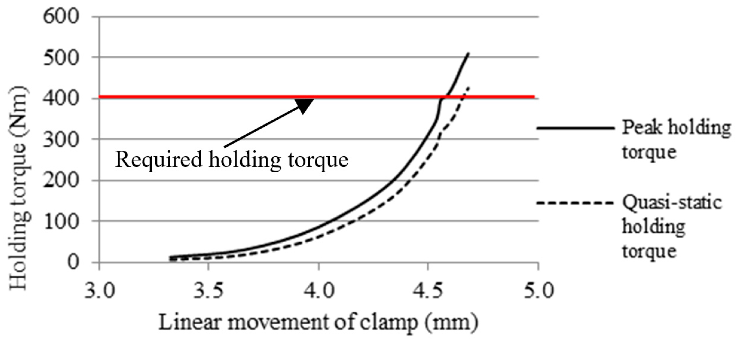
Numerous tests were completed to validate the performance of the brake, including trials using both the position and current control modes. The plateau in position in Figure 17 demonstrates the maximum movement possible with the selected actuator. Figure 18 presents the results showing the brake successfully holding more than the required 400 nm (red line).
Cyclic loading was also completed in order to observe the hysteresis effects present within the braking system. In this case, the Dartec machine was repeatedly loaded up to a 400 nm torque then released, with the associated rotary movement recorded. This is shown in Figure 19. In fact, the brake could resist over 700 nm at a peak current of 10 A, though only 5 A current limit ensures the brake can achieve the 400 nm specified holding torque. Due to the self-locking nature of the worm gear, the holding torques remained even after the power to the motor was cut, hence meeting the requirement within the PDS of continuous engagement for 48 h.
6. Conclusions
Through design synthesis of various brake sub-functions, a solution offering the greatest potential was identified. Characterising the performance of this solution showed that the in-line threaded clamping arrangement is a suitable design, having demonstrated its capability to transmit and maintain the required holding torque of 400 nm, as well as satisfying other key requirements from the PDS, including having an overall mass of 7.9 kg, under the target of 10 kg, fitting within the specified volumetric constraints, maintaining the full holding torque for over 48 h and engaging faster (6 s) than the set maximum (25 s). Noteworthily, the clamping arrangement achieved the required 400 nm of the holding torque below the maximum motion it could achieve. However, this could be interpreted as the brake being overdesigned if the device was reduced in size. Based on these findings, the clamping would result in the motion falling into the non-linear section, as described in Figure 5. However, this does offer a potential avenue during brake optimisation. This study demonstrates that the brake can meet the required specification, achieving a holding torque of 400 nm repeatedly with the selected Trimat MR2215 brake material, Maxon EC90 motor and Ondrive PF45 60:1 worm gearbox. In its current form, the brake satisfies the requirements of a system at high Technology Readiness Level (TRL6), as the prototype demonstrated functionality in a ground test environment. Subsequent work can now be completed to elevate the design to TRL7 and above, demonstrating operations within an actual helicopter platform. This can be done with confidence that all aspects of the brake were suitably validated and tested throughout service temperatures, as highlighted in the PDS.
Author Contributions
R.J.L. was the Research Assistant on the project and made the main contribution to this paper in terms of its technical content. D.D. was the project’s Principal Investigator and J.D.B. was the main supervisor on R.J.L., and corresponding author on the paper.
Funding
This research was funded by the European Union under their Clean Sky Green Rotorcraft initiative.
Acknowledgments
The authors would like to thank Keith Stickels and Martin Barber from Leonardo Helicopters, UK for their collaboration on this project.
Conflicts of Interest
The authors declare no conflict of interest.
Appendix A
Figure A1.
Morphological chart used during concept selection. (boxes indicates solution principles composing the winning concept solution).
Figure A1.
Morphological chart used during concept selection. (boxes indicates solution principles composing the winning concept solution).

References
- Avery, C.R.; Burrow, S.G.; Mellor, P.H. Electrical generation and distribution for the more electric aircraft. In Proceedings of the 2007 42nd International Universities Power Engineering Conference, Brighton, UK, 4–6 September 2007; pp. 1007–1012. [Google Scholar]
- Periodic Report Summary 2—HERRB (Helicopter Electric Regenerative Rotor Brake). Available online: https://cordis.europa.eu/project/rcn/104596/reporting/en (accessed on 24 July 2019).
- Podratzky, A.; Bansemir, H. Design and Experimental Characterization of Modern Helicopters Rotor Brakes. Aerosp. Sci. Technol. 2007, 11, 360–369. [Google Scholar] [CrossRef]
- Hartmann, H.; Schautt, M.; Pascucci, A.; Gombert, B. eBrake®—The Mechatronic Wedge Brake; SAE Techncial Paper No. 2002-01-2582; SAE International: Warrendale, PA, USA, 2002. [Google Scholar]
- Liao, Y.S.; Huang, C.T.; Chen, C.T.; Cheng, S.Y.; Chen, B.R.; Huang, F.Y. Novel Design of the Integrated Electric Parking Brake System; SAE Technical Paper No. 2010-01-1707; SAE International: Warrendale, PA, USA, 2010. [Google Scholar]
- Putz, M.H. VE Mechatronic Brake: Development and Investigations of a Simple Electro Mechanical Brake. In SAE Annual Brake Colloquium and Engineering Display; SAE International: Warrendale, PA, USA, 2010. [Google Scholar]
- Bayer, B.; Büse, A.; Linhoff, P.; Piller, B.; Reith, P.E.; Schmitt, S.; Schmittner, B.; Völkel, J.; Zhang, C. Electro-Mechanical Brake Systems. In Handbook of Driver Assistance Systems; Winner, H., Hakuli, S., Lotz, F., Singer, C., Eds.; Springer: Cham, Switzerland, 2015. [Google Scholar]
- Mott, R.L. Machine Elements in Mechanical Design, 3rd ed.; Prentice-Hall: Upper Saddle River, NJ, USA, 1999. [Google Scholar]
- European Aviation Safety Agency. Certification Specifications, Including Airworthiness Code and Acceptable Means of Compliance, for Large Rotorcraft “CS29”; Amendment 2: Cologne, Germany, 2008. [Google Scholar]
- Otto, K.N.; Wood, K. Product Design: Techniques in Reverse Engineering and New Product Development; Prentice-Hall: New York, NY, USA, 2001. [Google Scholar]
- Sclater, N.; Chironis, N.P. Mechanisms and Mechanical Devices Sourcebook, 3rd ed.; McGraw-Hill: New York, NY, USA, 2001. [Google Scholar]
- Fricke, G. Successful Individual Approaches in Engineering Design. Res. Eng. Des. 1996, 8, 151–165. [Google Scholar] [CrossRef]
- Fricke, G. Empirical Investigation of Successful Approaches when Dealing with Differently Precised Design Problems. In Proceedings of the International Conference on Engineering Design (ICED93), The Hague, The Netherlands, 17–19 August 1993; Heurista: Zürich, Switzerland, 1993; pp. 151–165. [Google Scholar]
- Lamers, K.L. Components of an Improved Design Process for Micro-Electro-Mechanical Systems; ProQuest: Ann Harbor, MI, USA, 2009. [Google Scholar]
- Shigley, J.E.; Mischke, C.R. Standard Handbook of Machine Design; McGraw-Hill: New York, NY, USA, 1996. [Google Scholar]
- Jang, H.K.K.; Kim, S.J.; Basch, R.H.; Fash, J.W. The effect of metal fibers on the friction performance of automotive brake friction materials. Wear 2004, 256, 406–411. [Google Scholar] [CrossRef]
- Osterle, W.; Dmitriev, A.I. Functionality of conventional brake friction materials—Perceptions from findings observed at different length scales. Wear 2011, 271, 2198–2207. [Google Scholar] [CrossRef]
- Chan, D.; Stachowiak, G.W. Review of automotive brake friction materials. Proc. Inst. Mech. Eng. Part D J. Automob. Eng. 2004, 218, 953–966. [Google Scholar] [CrossRef]
Figure 1.
Systematic diagram of a theoretical more electric helicopter including an electric rotor brake.
Figure 1.
Systematic diagram of a theoretical more electric helicopter including an electric rotor brake.

Figure 2.
Weighting strategy distribution.

Figure 3.
Overall weighted performance criteria.

Figure 4.
Winning concept (concept 1)—Worm gear driven threaded radial clamp with plain shaft frictional engagement.
Figure 4.
Winning concept (concept 1)—Worm gear driven threaded radial clamp with plain shaft frictional engagement.

Figure 5.
Force and notation of radial clasp arrangement.

Figure 6.
Required engagement force to maintain 400 nm holding torque over a range of radii and surface coefficient of frictions.
Figure 6.
Required engagement force to maintain 400 nm holding torque over a range of radii and surface coefficient of frictions.

Figure 7.
Reaction forces (N) at the pin (LHS).

Figure 8.
Testing platform.

Figure 9.
Example data of GBC material (engagement torque = 21 nm).

Figure 10.
Engagement torque versus quasi-static holding torque for various friction materials.

Figure 11.
Rotation rate variation versus peak holding torque for MR2215 friction material (6 nm engagement torque) (a) and MR8728 friction material (6 nm engagement torque) (b). The solid line is the peak torque and the dashed line is the quasi-static torque (with error bars ± 1 standard deviations).

Figure 12.
Hysteresis testing from top; (a) MR2215 with 6 nm engagement torque, (b) MR8728 with 6 nm engagement torque and (c) GBC with a 15 nm engagement torque. Loading cycle legend: Green line (5 s), red line (10 s) and blue line (20 s).
Figure 12.
Hysteresis testing from top; (a) MR2215 with 6 nm engagement torque, (b) MR8728 with 6 nm engagement torque and (c) GBC with a 15 nm engagement torque. Loading cycle legend: Green line (5 s), red line (10 s) and blue line (20 s).

Figure 13.
Engagement torque versus shaft radius (coefficient of friction = 0.9).

Figure 14.
2D representation of the inline threaded clamp arrangement.

Figure 15.
Estimated total mass of the inline threaded clamp arrangement.

Figure 16.
Electro-mechanical brake testing platform.

Figure 17.
Engagement position (qc) versus engagement time.

Figure 18.
Overall results showing the holding torque with increasing clamping motion.

Figure 19.
Cyclic loading—400 nm peak, 20 s period: (a) Torque versus time, (b) Torque versus rotation.
Figure 19.
Cyclic loading—400 nm peak, 20 s period: (a) Torque versus time, (b) Torque versus rotation.


Table 1.
Product Design Specification.
| Specification | Value |
|---|---|
| Holding torque (Nm) | 400 |
| Maximum radial dimension of system (mm) | 290 |
| Maximum axial dimension of system (mm) | 300 |
| Target system mass (kg) | <10 |
| Max. engagement period (without electrical input) (h) | 48 |
| Minimum safety factor (unit-less) | 1.5 |
| Temperature range (°C) | −55 to +85 |
| Time of engagement (s) | <25 |
| Time of depowered full holding torque capability (h) | 48 |
| Non-discrete engagement method | |
| Fail safe operation | |
Design intent:
|
Table 2.
Performance criteria and associated importance ranking.
| Criteria | Rank |
|---|---|
| Hold/locate resolution (continuous-discrete locking) | 1 |
| Low Unit mass/volume | 2 |
| High reliability/Low susceptibility to failure/Fault Tolerance | 3 |
| Low cost | 4 |
| Scalability | 5 |
| Robustness | 6 |
| High transmission efficiency | 7 |
| Installation ease/Maintainability/Serviceability | 8 |
Table 3.
Quasi static coefficients of friction at varying loading rates.
| Loading Rate | ||||
|---|---|---|---|---|
| Material | 0.01°/s | 0.1°/s | 1°/s | |
| GBC | Peak | 0.87 | 0.872 | 0.878 |
| Quasi-static | 0.855 | 0.855 | 0.852 | |
| MR2215 | Peak | 0.899 | 0.901 | 0.903 |
| Quasi-static | 0.895 | 0.899 | 0.899 | |
| MR8728 | Peak | 0.899 | 0.9 | 0.901 |
| Quasi-static | 0.895 | 0.897 | 0.897 | |
© 2019 by the authors. Licensee MDPI, Basel, Switzerland. This article is an open access article distributed under the terms and conditions of the Creative Commons Attribution (CC BY) license (http://creativecommons.org/licenses/by/4.0/).
Share and Cite
MDPI and ACS Style
Booker, J.D.; Lock, R.J.; Drury, D. Design and Physical Prototyping of a Novel Braking System for a Helicopter Rotor. Designs 2019, 3, 40. https://0-doi-org.brum.beds.ac.uk/10.3390/designs3030040
AMA Style
Booker JD, Lock RJ, Drury D. Design and Physical Prototyping of a Novel Braking System for a Helicopter Rotor. Designs. 2019; 3(3):40. https://0-doi-org.brum.beds.ac.uk/10.3390/designs3030040
Chicago/Turabian StyleBooker, Julian D., Richard J. Lock, and David Drury. 2019. "Design and Physical Prototyping of a Novel Braking System for a Helicopter Rotor" Designs 3, no. 3: 40. https://0-doi-org.brum.beds.ac.uk/10.3390/designs3030040