Redesign of an In-Market Conveyor System for Manufacturing Cost Reduction and Design Efficiency Using DFMA Methodology


School of Engineering & Built Environment, Anglia Ruskin University, Chelmsford, Essex CM1 1SQ, UK
*
Author to whom correspondence should be addressed.
Designs 2020, 4(1), 6; https://0-doi-org.brum.beds.ac.uk/10.3390/designs4010006
Submission received: 11 January 2020
/
Revised: 11 February 2020
/
Accepted: 13 February 2020
/
Published: 19 February 2020
Abstract
:To remain competitive in the market, it is crucial to reduce the time and costs involved in product development. Design for manufacturing and assembly is an engineering methodology that can reduce costs without compromising reliability, performance and time to market objectives. This paper presents a case study for an in-market Table Top Chain (TTC) conveyor system used by a reputed company in Saudi Arabia. TTC conveyor systems are extensively used by major food companies around the world for transporting packaged bottles, glass and cans. There are three main types of these systems, i.e., straight running, side flexing and multiflex. This work focuses on the redesign of a side flexing TTC conveyor system. The existing design of the TTC conveyor system was analysed using the DFMA 9.3 software. The outcomes of the initial analysis were utilised to redesign the TTC conveyor system for cost and design efficiency improvements. The optimum design was selected using Pugh controlled convergence method and further tested for its structural performance using finite element analysis. The redesigned model showed substantial improvements with cost reductions of 29% and an increase in design efficiency from 1.7% to 5%. Finite element analysis has also been carried out with SolidWorks 2019 to validate the structural integrity of the new concept design.
1. Introduction
Cost-effectiveness, ease of manufacture as well as assembly/disassembly are some of the factors that govern modern products. Design for Manufacture and Assembly (DFMA) is a well-established product design technique used to minimize the cost of production and development by designing products that utilise the simplest of components. Use of DFMA slows down the process briefly during the product conceptualization stage in terms of time because additional activities will take place to undertake DFMA. According to Boothroyd, Dewhurst, and Knight (2010), the extra time consumed while using DFMA techniques in the conceptualization stage is compensated by the savings in time when prototyping takes place [1]. DFMA is a practical design method that enables early consideration of the production aspect of manufacturing and assembly [2]. DFA (Design for Assembly) is about simplifying the product structure because the total number of components in a product is a key measure of design quality; fewer components result in a more efficiently assembled product. Design quality refers to the value of design to the customers in terms of their requirements. Design is the root of all quality including the quality of products, systems and processes. For example, a product with a poor design will be low quality even if the quality control and quality assurance succeed in producing the design accurately. Design quality can be improved by increasing features and functionality that can serve the needs and expectations of the customers. On the other hand, DFM (design for Manufacturing) concentrates on minimizing manufacturing complexity and exploring the costs of producing individual components. For example, reducing the features on a machined component will make it less expensive, increase quality and lend itself to further DFA activities [3]. There is no drawback in reducing the features if the functionality is delivered, and one of the salient features of DFMA is that it does not compromise functionality. Reducing the number of parts by joining several parts together is a common practice that can reduce assembly time. The implementation of these two philosophies as DFMA requires teamwork where designers, manufacturers and other relevant personnel should participate in the activities to achieve desired results.
Rima et al. (2015) used only the DFA manual approach to analyse and calculate the current and redesigned refrigerator component’s design efficiency. In their case study, some refrigerator freezer parts were altered and redesigned using DFA instructions. The new design was made with a distinct geometry, angle, decreased number of components and handling positions. From the refrigerator’s manual layout evaluation, the minimum parts of the door assembly were decreased from 38 to 29. From 69, the freezing room components were decreased to 54 and the refrigeration installation components from 328 to 110. The design effectiveness of the evaporator unit with the fan was enhanced from 58% to 78% and the design effectiveness of the fridge installation was enhanced from 38% to 63.9%. Design effectiveness is the measure of design efficiency. The more the design efficiency, the better the design of any given product. Design efficiency for the product development is calculated based on the theoretical number of parts, time taken to assemble the parts and total part count of the component. The calculations are shown below [4]:
Design efficiency of the current evaporator fan with motor’s design
where, = /
- = Design efficiency
- = Minimum number of parts
- = Basic assembly time for one part
- = Estimated time to complete assembly of the product
- = Total number of parts
- = [10 × (/196)] × 100
- = 58%.
Design efficiency of the redesigned evaporator fan with motor’s design
where = /
- = [7 × (/103)] × 100
- = 78%
Isanaka et al. (2016) analysed an air-breathing Proton Exchange Membrane Fuel Cell to simplify the manufacturing and assembly sequence of the conventional design fuel cell design. They achieved a 90% reduction in weight and number of components and close to 80% reduction in costs. Following a thorough reassessment of the most complex parts and assemblies in the conventional fuel cell, the researchers were able to converge to a much better design, which was superior in form factor while also being lightweight and portable [5]. Masood et al. (2005) carried out an investigation into the design and manufacturing of a mechanical conveyor system for the beverage processing industry and was able to reduce the assembly cost by 20% and material cost by 19%. The savings were calculated by conducting a cost analysis on the old conventional conveyor and the new system that was developed physically. The researchers identified critical parts, which were the leg set, side frame, support channel and bend tracks, which accounted for 70% of the conveyor cost. Using the minimisation of materials and principles of DFMA methodology, tangible results were produced. Cost of the conveyor leg was reduced from 114 USD to 59 USD and the number of parts required to make the leg decreased from 17 to just 11 parts. However, the research does not quantify the assembly time and labour cost required to manufacture the conveyors and design efficiency is also not shown [6].
There are many design concept selection methods that have been developed to assist designers to make the right decision of design concepts in the literature. The Pugh concept selection method is easy to use and is applied for simple decision making. This method involves qualitative comparison of each alternative to a reference or datum alternative, criterion by criterion. It is useful in conceptual design because it requires the least amount of detailed information. There are other more complex approaches, as well. For example, AHP (analytical hierarchy process) is a very comprehensive method and works well with many alternatives [7]. However, for limited choices and simple decision-making, the Pugh concept selection method is preferred [8]. DFMA results in designs that are based on several interwoven factors or criteria for which humans struggle to handle the complexity, resulting in inconsistent and irrational decisions. The Pugh Matrix provides a simple approach to taking these multiple factors into account when reaching a decision [9]. Muller et al. (2011) used Pugh Control Convergence method (PuCC) to explore alternate designs in connection to the rigid flow-line spool for sub-sea equipment, such as a flowline link the Pipeline End Termination Structure (PLETS) with the manifold at the bottom of the ocean in oil production regions. The flow line is a huge oil and gas transportation pipe that must resist high stresses and temperatures. Each flowline is currently custom engineered and produced to accommodate the specific geography at the bottom of the ocean. This is quite a challenge when the geography is changed, since a new customized flow-line spool must be developed to meet the new requirements. By inserting several swivel elements, the researchers explored the option of making a more versatile flow line. These swivels function as hinges facilitating a certain degree of freedom of angle in the flowline. The researchers explored three alternatives that could serve the purpose and labelled CBV swivel, Clamp swivel and Dynamic swivel under concepts 1, 2 and 3, respectively. Each concept has distinct features and PuCC was used to compare different concepts. The evaluation criteria used to rate and compare were maturity, cost, installation, operation characteristics and design robustness. After thorough analysis, the selection matrix showed that the dynamic swivel ratings in all aspects were the best, and therefore it was taken forward to the detailed design stage [10]. Thakker et al. (2009) carried out a case study where many conceptual designs of impulse turbine were developed, and those concepts were further evaluated using the Pugh decision matrix to arrive at the final optimal design. The research used a systematic technique to display the design of an enhanced impulse turbine combining two strong design instruments, i.e., Pugh concept analysis and 3DCAD environment. Using this strategy, the researchers merged the power of Pugh’s technique with the design space to select the optimal concept by filtering out the less desired concepts. Each concept was carefully rated based on the chosen evaluation criteria that were manufacturability, safety, development cost, reliability, simplicity and maintenance. The best concept was picked after running several iterations and the optimum design was also tested for structural performance against different materials using FEA (finite element analysis) to validate the design [11]. Medvecká-Beňová (2017) performed a strength analysis on a trailer frame using FEM. The trailer was typically built for a private sector business to transport little ships or water scooters. The frame is mounted to resist stresses and impacts that may occur during building and operation. The design of the trailer is a galvanized welded framework. The trailer truck is intended to weigh up to 750 kg in total. The maximum payload weight is 450 kg because the weight of the distinct trailer is 240 kg. The frame was simulated using SolidWorks Simulation Professional. Prior to the analysis, the appropriate material was selected, which is the galvanized steel, the boundary condition and suitable fixtures were defined followed by the creation of mesh and application of loads as 4650 N. The simulation identified maximum stress locations with σ max = 118.8 MPa. The maximum stress value did not exceed the maximum allowable criteria, which is 210 MPa, and therefore the design was deemed safe [12].
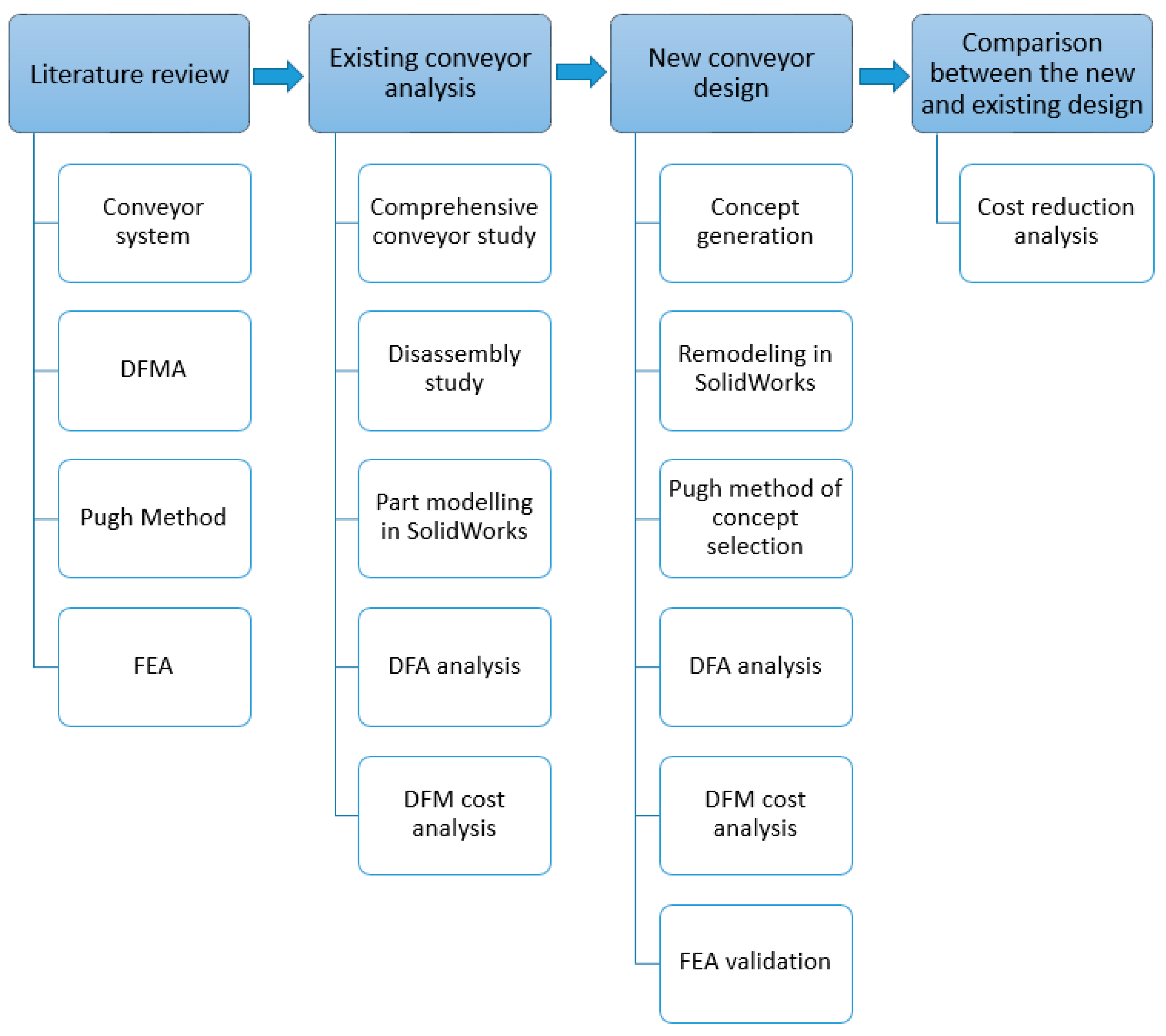
Modern methods of production dictate the use of material handling systems. Conveyors, a type of manufacturing system, are a key part of large-scale production and ongoing processes. Conveyors consist of fixed and mobile equipment capable of continuously or intermittently moving material between two or more points along a fixed path. Material movement is horizontal, vertical, inclined, or any of the three combinations. These systems are used in a variety of areas including agriculture, food processing, plastics and mining. For transporting materials, two fundamental techniques are used, i.e., non-powered material handling technologies and driven material processing technologies [13]. This research only deals with the powered conveyor system and more particularly the table top chain conveyor system that is extensively used in the food and beverage processing plants. TTC (table top chain) conveyors are unique in the processing industry, as they comprise a drive, intermediate, idler and curve section. A good characteristic of any TTC conveyor, regardless of its application, is its ability to incorporate a variety of chain mechanisms, to be flexible enough to transfer the product in parallel or 90-degree orientation, and guide the product to ensure its safety. According to McGuire (2009), there are three main types of TTC conveyors. The first is when the top plate forms an essential part of the connection known as straight running, the second is when the top plate is fitted on a base chain known as side flexing and the third is called multiflex that uses a ball joint to increase flexibility. All three types can be configured for special purposes. In this work, DFMA has been utilised to redesign an in-market TTC conveyor system to achieve cost reductions and increased design efficiency [14]. A brief overview of the general procedure for DFMA analysis is shown in Figure 1.
2. Case Study of TTC Conveyor System
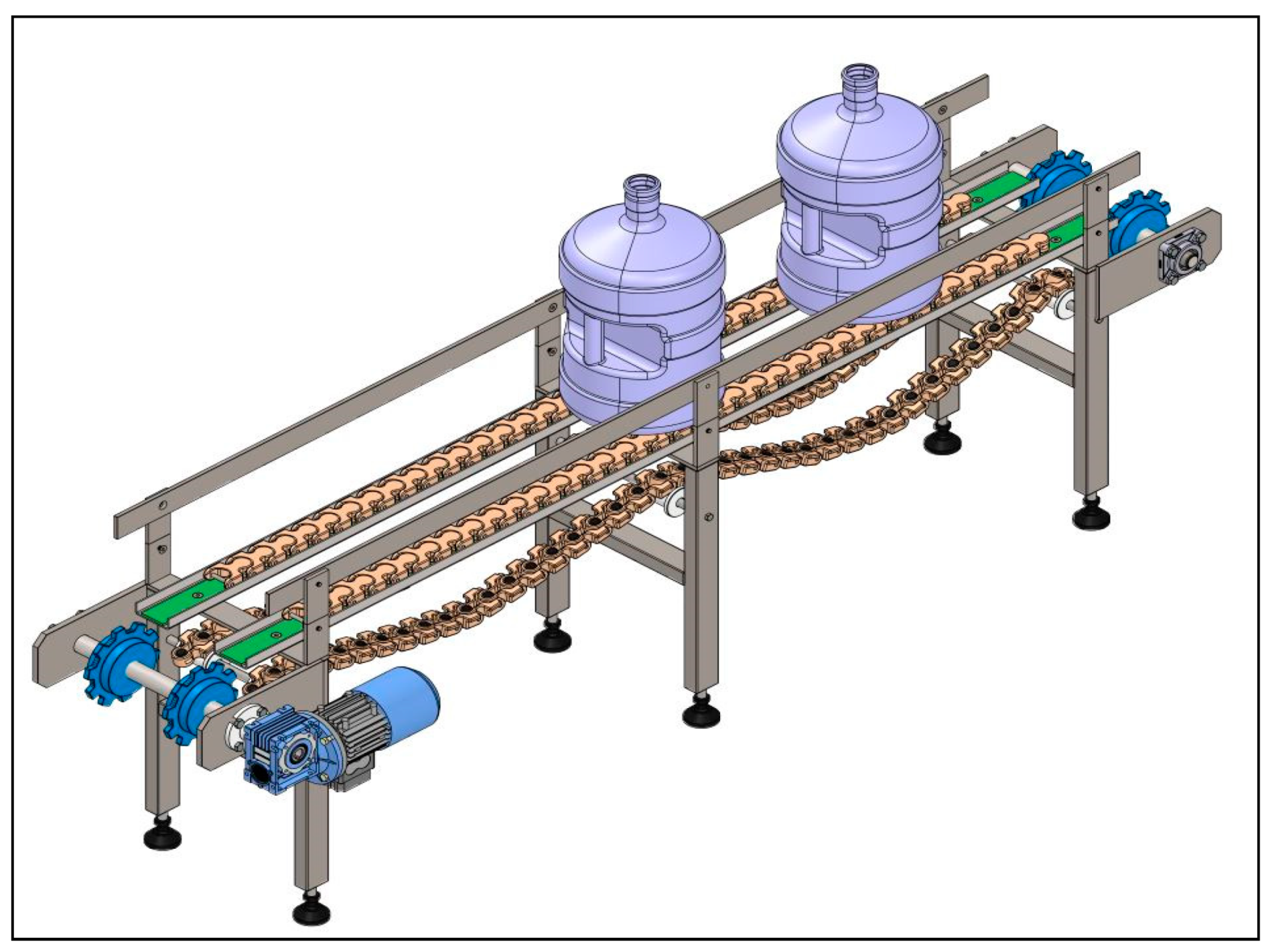
The TTC conveyor system is extensively used in the food and beverage processing plants. Conveyor system design and production are complex processes that take enormous time. Because every conveyor system is a customized machine based on the requirements of a production facility, there are several factors that are considered. The task of designing a conveyor system layout involves revisions and could take weeks or months. A cost-effective system capable of meeting customers’ demands is likely to get approval. Such a system was selected for a reputable bottle manufacturing and filling facility in Saudi Arabia. Figure 2 shows a CAD model of a side flexing TTC conveyor system. It has a length of 6 m and is used for transferring damaged/rejected bottles. Damaged bottles are characterised by visual defects, discoloration or bad odour. All three activities are performed by humans. DFMA analysis was carried out on this conveyor system. Typically, such systems are built from concepts arising from market competition, customers’ requirements and new manufacturing technologies. However, DFMA principles were not taken into consideration for its design and manufacture/assembly. This work focusses on improving the cost-effectiveness and design efficiency by systematically analysing different parts of the TTC conveyor system.
2.1. Product Structure Chart for Reject Conveyor
The TTC Reject conveyor comprises three main subassemblies: the front drive straight section, the 90-degree curve section and the idler straight section. These three main sections consist of miscellaneous parts, as shown in Figure 3.
The original equipment manufacturer follows the “one man, one conveyor” philosophy where each conveyor is assembled by a single technician. The assembly sequence followed by the technician who assembled the Reject conveyor was recorded and that helped in creating the product structure chart. It is in order of the configuration of how the product is built systematically. As shown in Figure 3, the technician first starts with ‘front drive straight section’. In this assembly, the first part that is picked and brought to the worktable is the ‘side frame 3 mm right’. The first part is always the base part on which the assembly is built. The second step is to insert rivet nuts into holes of the frame and, once the rivet nuts are properly secured, the next step is to fasten them using the hand-operated rivet tool, which is considered as the third step. In the fourth step, the technician spot welds the rivet nuts to prevent them from loosening from vibrations during conveyor operations, and hence the sequence continues until this section is fully assembled.
Similarly, the first five sequences for the 90-degree curve section are also shown in Figure 3 where ‘SS curve frame small’ is the base part upon which the assembly is built, and sequences continue until this section is fully assembled. For the ‘idler straight section’, only the last three sequences are shown. It implies that upon the completion of assembly for these three last parts, the conveyor is deemed to be fully assembled.
The product structure with the complete assembly sequence for the Reject conveyor is shown in Appendix A. The icons as shown in the chart hold special meaning and are defined in Table 1.
2.2. Sequential Disassembly of Reject Conveyor
Sequential product disassembly was performed to study assembly order and related handling challenges. The symmetry is one of the main features of geometric design that affects the time needed to grasp and orient a part. According to Demoly et al. (2011), there are two types of symmetry: alpha and beta symmetry. The former depends on the angle through which a part must be rotated about an axis perpendicular to the axis of insertion to repeat its orientation, whereas the latter depends on the angle through which a part must be rotated about the axis of insertion to repeat its orientation [15].
To undertake disassembly of the Reject conveyor, the CAD model of the conveyor is exploded to determine the part handling of each component. The exploded views help in determining the appropriate symmetry, which is an essential input parameter required by the DFA software. The part handling is classified into alpha (axis perpendicular to direction of insertion) and beta (axis in direction of insertion) symmetry, as shown in Figure 4. Defining appropriate symmetries is the primary requirement of the DFMA software to determine the assembly efficiency.
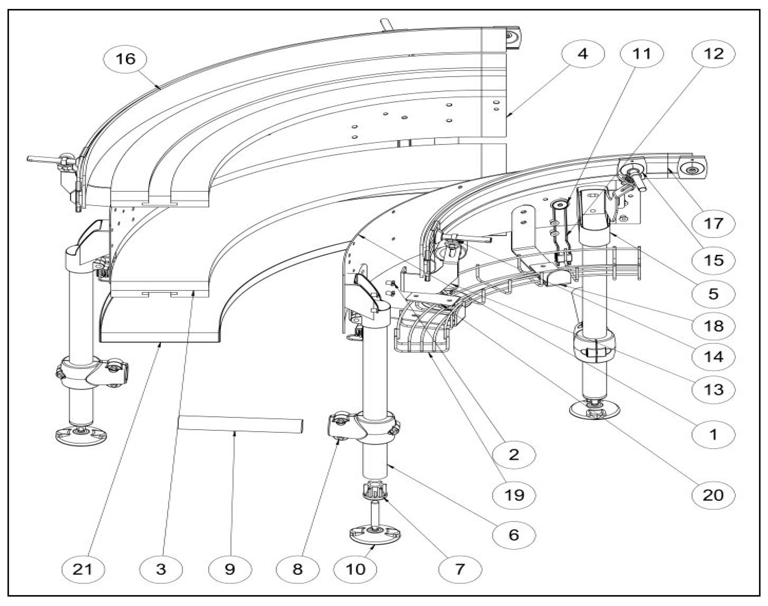
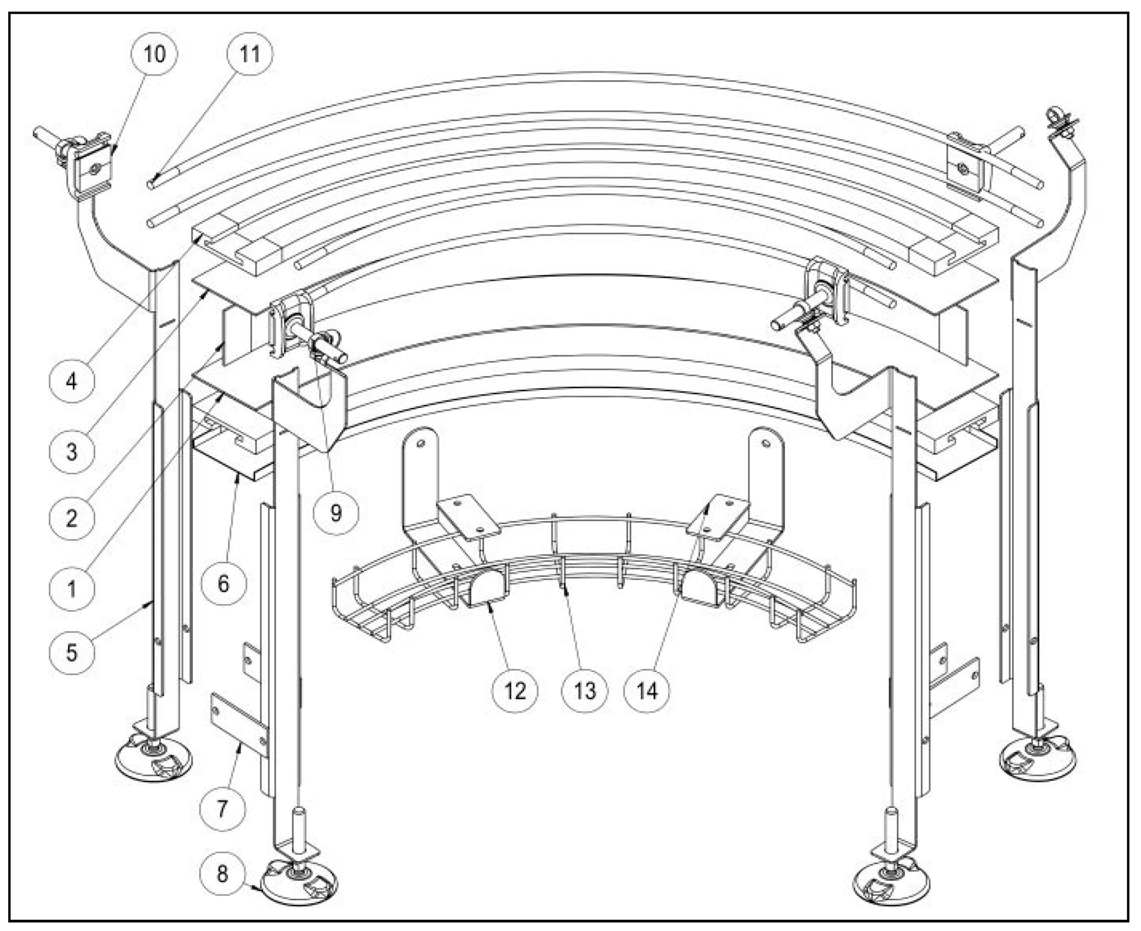
As seen from Figure 5, the first item has alpha and beta of 180 degrees. The second item has alpha and beta of 180 degrees and 90 degrees, respectively, whereas the angle symmetry for the third object is 0 degrees. Each component of the Reject conveyor system is exploded to determine the alpha and beta symmetry which are then used in the software to calculate design efficiency. The exploded view for ‘front drive straight section’ is shown in Figure 5 and its corresponding parts are shown in Table 2.
To understand the symmetry further, refer to part 18, which is the ‘side mounting top bracket’. This mounting bracket must be fixed in just one way and it cannot be rotated on either the alpha or beta axis, and therefore ‘One Way’ symmetry was selected in the software, as shown in Figure 6.
2.3. Material Selection and Manufacturing Process for Reject Conveyor
It is important for engineers to better comprehend the pros and cons associated with an ‘informed selection’ of the materials selected for a product, the associated manufacturing process and, most importantly, the suppliers of the material, components, and subassemblies used in a product. According to Pfeifer (2009), such an understanding will assist in defining appropriate policies for risk mitigation and will help in managing expectations [16]. However, the material and manufacturing processes in relation to the Reject conveyor were available from the original equipment manufacturer since it was already produced.
Appendix B shows the full list of parts, the material and manufacturing process selected, total weight, as well as the total cost for the Reject conveyor. The cost price for parts that were manufactured using in-house capabilities was estimated using the DFM software and the remaining costs for parts bought from vendors were entered directly into the system and labelled as ‘Purchase’ in the manufacturing process column as shown in Appendix B. According to Appendix B, the total cost for the manufacture of the TTC Reject conveyor is 2284.18 GBP and its total weight is 264.84 kg. To execute the DFMA analysis, a product structure chart was constructed in DFA software. Every single entry in the product structure was examined by the envelope dimension, securing methods, part symmetry, handling requirements, insertion and handling difficulties. Simultaneously, the entries on the structure chart were cost-estimated using DFM concurrent software, based on their part profile, choice of material and manufacturing process. The overall plant efficiency was considered as 85% and the labour rate of 26 GBP/hour in the UK was taken according to Eurostat [17].
It was found that the total cost for manufacturing the Reject conveyor is estimated to be around 2284 GBP with item cost alone to be 2221.72 GBP and labour cost of 62.47 GBP. The theoretical minimum part count is 42 and DFA Index is 1.7. The DFA index is a figure obtained by dividing the theoretical minimum assembly time by the total assembly time. The equation for calculating the DFA index, , is given below:
where, = Minimum number of parts,
- = Basic assembly time for one part,
- = Estimated time to complete assembly of the product.
A comprehensive report showing the repeat counts, securing method, minimum part criteria, handling, insertion and ergonomic problems associated with the Reject conveyor was automatically generated by the software and is given in Appendix C. A detailed analysis like handling time, insertion time, labour time, labour cost and item cost associated to all sections of the Reject conveyor is given in Appendix D.
3. Generation of New Concepts
Concept generation is all about creating new ideas and is often considered the most crucial step in the engineering design process because it is in this step that 70%–80% of the product price is committed [18]. Following the implementation of various design techniques, such as brainstorming during the concept generation stage, three design alternatives of the conveyor system that can replicate the Reject conveyor without affecting the functionality are presented in Section 3.1, Section 3.2 and Section 3.3. Three main factors were considered while generating the new designs: ability to accommodate different product sizes, hygiene, and ease of assembly.
3.1. Concept 1: Dual Lane Flex Type Conveyor System
This design features a double lane chain, running parallel and driven by a single motor. The design constitutes simple architecture with fewer parts. The conveyor frame is made mainly from tubular sections, and very few sheet metal parts have been used except for the product side guide and bearing support. The tubes are standard profiles which are cheaper and could significantly reduce the overall price of the conveyor. The product side guide as seen in Figure 8 is very much similar in shape to that used in the Reject Conveyor but lacks the necessary hardware to accommodate different product sizes. The belts can be easily cleaned, thus providing better conveyor hygiene. Turning disk transfer can be easily incorporated with this system, hence eliminating the need of a curve system for transferring products at 90 degrees.
3.2. Concept 2: Narrow Lane Conveyor System
This conveyor features a single belt having narrow lane configuration in which the conveyor frame width is only 85 mm as compared to the frame width of the Reject conveyor, which is 205 mm. A CAD model of this concept is shown in Figure 9. The conveyor is made from both stainless steel and aluminium. Stainless steel is used in the areas where food makes contact, while the aluminium profile is for constructing the leg assembly as it offers a high degree of flexibility in joining, hence reducing assembly time. The product side guide is a simple round bar and can be adjusted both horizontally and vertically to accommodate different sizes of products. The conveyor’s modular structure can reduce assembly operation and labour cost, but hygiene is compromised due to its closed frame configuration.
3.3. Concept 3: Conveyor with an I-Beam Substructure
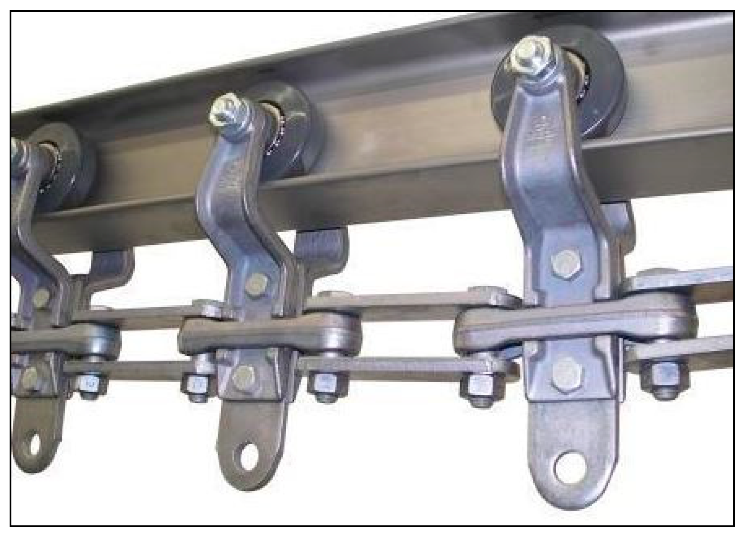
A CAD model for this concept is shown in Figure 10. This conveyor features an I-beam profile made from 3-mm thick stainless-steel sheet. This specific configuration for making a food conveyor has not been utilised before and is quite unique. Only overhead chain conveyors that are employed to transport bulky product utilise the beam profile as a track, as shown in Figure 11. One good aspect of having an I-beam shaped frame, unlike the box section frame of the Reject Conveyor, is that it does not require the use of rivet nuts. Rivet nuts, also known as blind nuts, are used in sheets of wall thickness less than 5 mm because it is extremely challenging to tap threads in plates of wall thickness less than the specified. Rivet nuts were extensively used previously in the Reject conveyor to fasten bolts for securing conveyor components. This design also eliminates the use of connector pins previously used to hold the frames together, as shown in Figure 5. Furthermore, the conveyor has an open frame configuration to facilitate cleaning and hygiene.
3.4. Controlled Convergence Method
Pugh proposed that product development engineers should participate in an iterative method of adding and removing a range of concepts at an early point in the design phase after identifying requirements but prior to a comprehensive design. He developed a method of controlled convergence which is an iterative and non-numeric tool that improves and narrows the choice of concepts available. ‘Controlled convergence’, developed by Stuart Pugh in the 1980s, utilises a convenient matrix to compare concepts with a selection of predetermined requirements [19]. The decision matrix is built based on Pugh’s technique to evaluate and rate the ideas. The best concept is accepted based on comparing the ratings for different concepts and eliminating the associated issues.
Several factors were considered for the evaluation criteria: material cost, manufacturing cost, repair cost, ease of fabrication, weight, strength, reliability and simplicity of design, styling, recyclability of materials, ease of repair, installation and disassembly. The decision matrix was formulated by entering the evaluation criteria as columns and concepts as rows. According to Pugh (1991), a datum is chosen as a reference against which all other concepts will be compared. If a design (or designs) already exists for a product area under consideration, it must be included in the matrix and always forms a useful datum choice. In this case, the Reject conveyor which already exists is considered as a datum. Each concept/criterion is considered against the chosen datum. The following legends are used [8]:
- ▪
- + (plus) meaning better than, cost less than, less prone to, easier than, etc., relative to the datum.
- ▪
- − (minus) meaning worse than, more expensive than, more difficult to develop than, more complex than, more prone to, harder than, etc.
- ▪
- S (letter) meaning the same as the datum is used when doubt exists as to whether a concept is better or worse than the datum.
The results for each alternative are achieved by adding the graded scores in the PuCC decision matrix. The optimal solution is selected based on the scores obtained. The optimal alternative is considered with a greater number of plus ratings and fewer minus, as seen in Table 4. Furthermore, concepts both having ‘+’ (as seen for material cost in Table 4) can have different levels of criteria and that can be overcome by using extra levels of discrimination as proposed by Pugh [8]:
- ‘++’ = much better
- ‘—‘ = much worse
As seen in the table, both concepts 1 and 3 are desirable as they have the same number of positive scores, but concept 3 has fewer minuses as compared to concept 1, and therefore, concept 3 is a strong candidate to take forward to the final design stage. This is the conveyor with an I-beam substructure (Section 3.3).
3.5. Development of the New Conveyor with the I-Beam Substructure
After confirming concept 3 as the optimal solution, this conveyor entered the detail design stage. In this stage, various factors were determined, e.g., specific shape and size of the individual components, material selection, assembly and manufacturing methods. The detailed design is developed by strictly following the DFM guidelines to enhance design efficiency and reduce cost. According to the DFMA framework, the new design was processed using the steps shown in Figure 12 to calculate the DFA index and estimate the new cost. This data is crucial to quantify and acknowledge the improvements by comparing the new design with the existing design.
3.5.1. Product Structure Chart for New Conveyor
The new conveyor with I-beam substructure is shown in Figure 13 and comprises the same three main subassemblies as the original Reject conveyor. However, these subassemblies were redesigned (drive straight section new, curve section new and idler end section new) and the product structure with the complete assembly sequence is shown in Appendix E.
3.5.2. Sequential Disassembly of New Conveyor Design
Sequential product disassembly was once again performed and the exploded views for ‘drive straight section new’ and ‘curve section new’ are shown in Figure 14 and Figure 15. Their corresponding parts are shown in Table 5 and Table 6. The exploded view for ‘idler end straight section’ is not shown since its product architecture is like the drive section new type. Appendix F shows the full list of parts, the material and manufacturing process selected, total weight and total cost for the making the new conveyor.
3.5.3. DFMA Analysis for the New Conveyor Design
Once again, every single entry in the product structure for the new design was examined by its envelope dimension, securing methods, part symmetry, handling requirements, insertion and handling difficulties. Every single part was cost estimated based on its part profile, choice of material and manufacturing process. The total cost for making the new conveyor system was estimated to be around 1616.37 GBP with item cost alone to be 1589.67 GBP and labour cost of 26.62 GBP, as shown in Appendix F. The theoretical minimum part count is 50 and DFA Index is 5.0. A comprehensive report showing the repeat counts, securing method, minimum part criteria, handling, insertion and ergonomic problems associated with the new conveyor system is given in Appendix G. A detailed analysis of handling time, insertion time, labour time, labour cost and item cost associated with all sections of the new conveyor design is given in Appendix H.
4. Design Improvements Resulting from DFMA Implementation
DFMA principles helped in modifying the existing design that resulted in many improvements. DFA criteria have been applied by eliminating and modifying different components. However, it is important to note that not all the components that do not meet the DFA criteria can be removed or combined with other components, due to various factors like strength and cost of manufacturing. For example, the I-beam of the new conveyor is made from three parts, i.e., frame flange part bottom, frame web part, and frame flange part top, as seen in Figure 13. The web part is the base part but the other two parts according to DFA criteria are labelled as unnecessary parts because they do not have to be made from a different material, do not have any relative motion with respect to the base part and also do not have to be separate components for assembly/disassembly, and therefore, the criteria calls for combining and making them as one part. However, manufacturing a customizable I-beam only for the sake of producing conveyors would add up manufacturing tooling cost and is not viable since different frame widths will be used for different applications. Therefore, it is crucial that companies and designer make a viable decision while evaluating the DFA criteria. Table 7 demonstrates the proposed modifications of the new conveyor system. Both the old and new designs are compared to show modifications and their cost implications.
It is evident from Table 7 that majority of the savings came from having a simplified frame configuration, by replacing the product side guide and flat bar plate with a simple 12-mm round bar and by eliminating the need of having a guide rail bracket. It is noted that the savings made are mainly achieved by modifying or eliminating the conveyor components that were over-designed and lacked professional planning. This validates the view that design simplification can lead to significant cost savings, regardless of its simplicity.
4.1. Results from DFMA Software
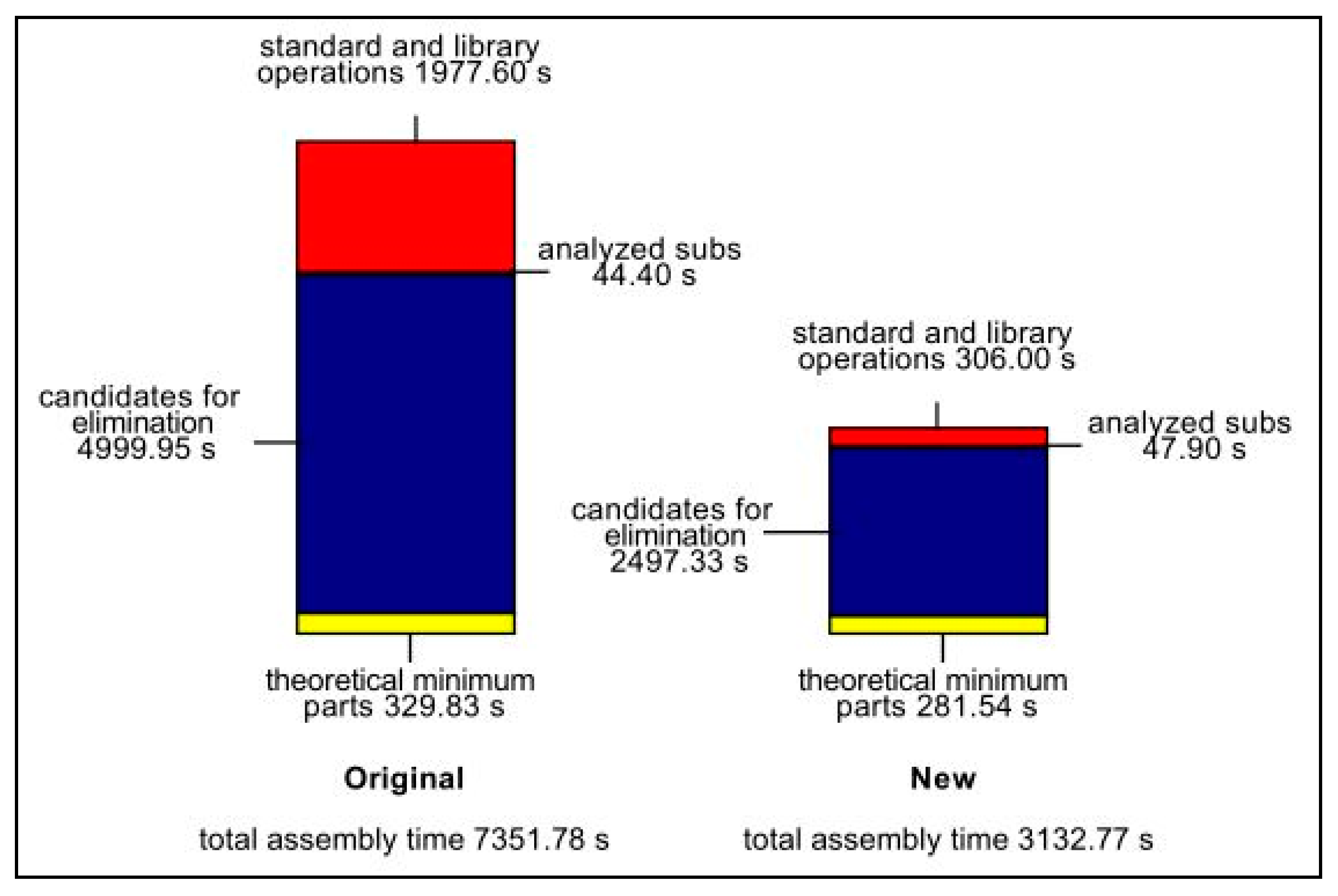
Design efficiency and cost analysis for the conveyor system were calculated using the DFA product simplification software and DFM concurrent costing software, respectively. Table 8 shows the comparative analysis of the old and new conveyor systems. The new design is superior to the old one on many fronts, i.e., reduction in weight (from 261.76 kg to 197.04 kg), reduction in assembly labour time (from 7351.78 s to 3132.77), reduction in labour cost (from 62.47 to 26.62 GBP), reduction in per product costs (from £284.18 to £1616.37 GBP) and increase in DFA index (from 1.7 to 5.0). Figure 16 illustrates the breakdown of time for assembling each conveyor.
4.2. Results from Using PuCC for Concept Selection
PuCC was used as an effective tool in narrowing down the different concepts generated for improving the old conveyor system. During the project, it was demonstrated to be both an evaluation and a visual communication tool that helped in making a better engineering decision. As shown in Table 4, concept 3 was identified as the best concept based on a greater number of pluses and fewer minuses. The results obtained after critically analysing the merits and demerits of different conveyor systems based on various criteria like weight consideration, manufacturing cost and ease of fabrication are further justified by the DFMA analysis.
By focusing heavily on the criteria as described in Section 3.4, PuCC eliminated the uncertainties during the concept selection phase and promoted decision-making processes more through facts and less through emotional attachment to favourite ideas. The research concludes that ideation and evaluation should be conducted simultaneously and that PuCC has a central role to play.
5. Validation of New Concept Using FEA
The frame is an integral part of the conveyor system since all the conveyor components and accessories are mounted on it and it must be rigid enough to sustain different loads and impacts exerted by the moving products. The new conveyor frame design is a prismatic I-beam structure. Structural steel constructions are designed with I-beams because of their high efficiency. I-beams have an innate ability to bend unidirectionally parallel to the web. The horizontal flanges are resistant to bending movement and the web resists the shear stress. Without buckling, they can handle different kinds of loads and shear stresses. They are also economical as the ‘I’ form is an industrial structure that does not use excess steel [20].
As seen in Figure 16, the ‘Idler end section new’ is the longest part of the conveyor, which is supported by three pairs of legs. The total length of this section is 3.5 m and can accommodate a maximum of 14 big bottles. Each filled bottle is 5 gal, which is roughly 20 kg maximum, therefore, 14 bottles exert a load of 280 kg. Furthermore, considering the weights of the conveyor components, gravity and dynamic aspects, the total load exerted on the conveyor frame of 3.5 m is approximated to be 500 kg. However, to ensure maximum safety, the strength analysis on the conveyor frame is carried out with 1 tonne (9806 N) loading with just two supports. This is achieved by treating the conveyor frame as a simply supported beam that has hinge support at one end and a roller support at the other [21]. First, the beam is analysed using the analytical methods and the results obtained are validated using FEM.
5.1. Analytical Calculation of Deflection and Stress
The free-body diagram (FBD) for the beam and its cross-section is shown in Figure 17.
For a simply supported beam, the maximum deflection can be calculated using the formula below [22,23]:
where,
| p | Load Intensity = | 2.80 N/mm |
| l | Length of the beam = | 3500 mm |
| E | Modulus of elasticity = | 190,000 MPa |
| I | Moment of Inertia = | 1,943,603.75 |
The moment of inertia for the ‘I’ cross-section was directly obtained from SolidWorks software. Substituting all the known values in Equation (4) gives the following solution:
For a simply supported beam, the maximum stress can be calculated using the formula [24]:
where M is the maximum bending moment, which is given by
and y is the distance from the neutral axis and is equal to 50.5 mm.
Substituting the known values in Equation (8) gives the following solution:
Substituting the value of and y in Equation (7) gives the following:
The analytical results for deflection and stress were compared to the finite element models made in SolidWorks and are discussed in Section 5.2.
5.2. Stress Analysis and Deflection Using FEM
A static study on the beam element (Beam with uniformly distributed loads) was carried out in SolidWorks Simulation Software. Stainless steel 304 from the material library was assigned to the beam. For simulation, immovable boundary condition constraints were applied on the hinges so that the beam could only move in the vertical direction to show deflection and stresses. The model was meshed using the SolidWorks Simulation’s beam mesh feature. Gravity was applied as a loading condition and a load of 9806 N was applied on the top face to observe axial bending, as shown in Figure 18. As seen in Figure 18, the maximum stress is in the middle of the beam and its value is 111 MPa. The maximum stress did not exceed the permissible stress of 207 MPa and hence the factor of safety (FOS) is greater than 1 (or equivalent to 1.86).
The deflection of the conveyor frame is shown in Figure 19. The maximum deflection occurred at the middle of the span (where maximum stress was previously obtained) and its value is 15.046 mm. At this point, the deflection is much lower in practice because the middle portion of the frame is connected by a pair of legs. Table 9 shows a comparison between the analytical and numerical values. It is evident that the values are very close to each other, showing that the simulation model can be used to model different loading conditions with different materials in the future as well. More importantly, these values show that the new design beam can meet the strength requirements needed for the system.
6. Conclusions
The paper presents an investigation into the design and manufacturing of a mechanical conveyor system used in the food industry with the help of a DFMA tool and techniques. A full breakdown analysis of the existing conveyor system was carried out to identify and eliminate critical parts that were either not professionally designed or overdesigned, or which have cost implications in conveyor manufacturing. By considering all the critical parts, the new conveyor design was developed by applying principles of DFM and DFA in conjunction with analysing alternative design concepts that led to better design efficiency and reduced manufacturing cost without sacrificing functionality.
The following conclusion can be drawn from the work presented in this paper:
- (1)
- The time and cost required to assemble the new conveyor system were reduced by 57%.
- (2)
- The weight of the conveyor was reduced by 25%, leading to ease of transport.
- (3)
- The overall manufacturing cost was reduced by 29% for the new conveyor system.
- (4)
- Originally 27% of total assembly time for old conveyor design was consumed by fixing mechanical fasteners and joining operations that included riveting and welding. For the new design, the standard operation only consumed 10% of the total assembly time, thus saving significant time.
- (5)
- The DFA index or the design efficiency improved from 1.7% to 5%, showing that it is easier to assemble the new conveyor system.
Author Contributions
J.B. and S.J. conceptualized the idea and defined the methodology; S.J. investigated different designs and wrote the first draft; J.B. and S.J. conducted comparative design analysis; J.B. worked on manuscript review and editing. All authors have read and agreed to the published version of the manuscript.
Funding
The research did not receive any external funding.
Conflicts of Interest
The authors declare no conflict of interest.
Appendix A. Assembly Sequence for the Reject Conveyor


Appendix B. Manufacturing Process and Material Information for Existing Conveyor Design


Appendix C. Table Showing the Repeat Counts, Securing Method, Minimum Part Criteria, Handling, Insertion and Ergonomic Problems for Existing Design


Appendix D. Handling Time, Insertion Time, Labour Time, Labour Cost and Item Cost Associated with All Sections of the Existing Conveyor


Appendix E. Assembly Sequence for the New Conveyor

Appendix F. Material and Manufacturing Process Information for New Conveyor Design


Appendix G. Table Showing the Repeat Counts, Securing Method, Minimum Part Criteria, Handling, Insertion and Ergonomic Problems for New Design


Appendix H. Handling Time, Insertion Time, Labour Time, Labour Cost and Item Cost Associated with All Sections of the New Conveyor


References
- Boothroyd, G.; Dewhurst, P.; Knight, W.A. Product Design for Manufacture and Assembly, 3rd ed.; Taylor & Francis: Milton Park, UK, 2010. [Google Scholar]
- Sudin, M.N.; Chin, N.S.; Shamsudin, S.A.; Yusuff, M.A. Design Efficiency Analysis towards Product Improvement for Eco-Friendly Using DFMA Method. Open Mech. Eng. J. 2016, 10, 173–181. [Google Scholar] [CrossRef] [Green Version]
- Dittmar, H. DfM, DfA & DfMA–What’s the Difference? 2019. Available online: https://www.gmisolutions.com/blog/the-difference-between-dfm-dfa-and-dfma (accessed on 12 December 2019).
- Rima, S.; Hong-Seok, P.; Gyu-Bong, L. Design for assembly: an approach to increase design efficiency of electronics home appliance. Ann. Daaam Proc. 2015, 26. [Google Scholar] [CrossRef]
- Isanaka, S.P.; Sparks, T.E.; Liou, F.F.; Newkirk, J.W. Design strategy for reducing manufacturing and assembly complexity of air-breathing Proton Exchange Membrane Fuel Cells (PEMFC). J. Manuf. Syst. 2016, 38, 165–171. [Google Scholar] [CrossRef]
- Masood, S.H.; Abbas, B.; Shayan, E.; Kara, A. An investigation into design and manufacturing of mechanical conveyors systems for food processing. Int. J. Adv. Manuf. Technol. 2005, 25, 551–559. [Google Scholar] [CrossRef]
- Hambali, A.; Sapuan, S.M.; Rahim, A.S.; Ismail, N.; Nukman, Y. Concurrent decisions on design concept and material using analytical hierarchy process at the conceptual design stage. Concurr. Eng. 2011, 19, 111–121. [Google Scholar] [CrossRef]
- Pugh, S. Total Design: Integrated Methods for Successful Product Engineering; [e-book]. Addison-Wesley Publishing Company, 1991. Available online: https://books.google.co.uk/books?id=RKIQAQAAMAAJ (accessed on 12 December 2019).
- Frey, D.D.; Herder, P.M.; Wijnia, Y.; Subrahmanian, E.; Katsikopoulos, K.; Clausing, D.P. The Pugh controlled convergence method: model-based evaluation and implications for design theory. Res. Eng. Des. 2009, 20, 41–58. [Google Scholar] [CrossRef] [Green Version]
- Muller, G.; Klever, D.G.; Bjørnsen, H.H.; Pennotti, M. Researching the application of Pugh Matrix in the sub-sea equipment industry. In Proceedings of the CSER, Los Angeles, CA, USA, 15–16 April 2011. [Google Scholar]
- Thakker, A.; Jarvis, J.; Buggy, M.; Sahed, A. 3DCAD conceptual design of the next-generation impulse turbine using the Pugh decision-matrix. Mater. Des. 2009, 30, 2676–2684. [Google Scholar] [CrossRef]
- Medvecká-Beňová, S. Strength analysis of the frame of a trailer. Sci. J. Sil. Univ. Technol. Ser. Transp. 2017, 96, 105–113. [Google Scholar]
- Fayed, M.E.; Skocir, T. Mechanical Conveyors: Selection and Operation; CRC Press. Taylor & Francis, 1996. Available online: https://books.google.co.uk/books?id=ZLI4i_iSfG8C (accessed on 12 December 2019).
- McGuire, P.M. Conveyors: Application, Selection, and Integration; CRC Press: Boca Raton, FL, USA, 2009. [Google Scholar]
- Demoly, F.; Yan, X.T.; Eynard, B.; Rivest, L.; Gomes, S. An assembly oriented design framework for product structure engineering and assembly sequence planning. Robot. Comput. -Integr. Manuf. 2011, 27, 33–46. [Google Scholar] [CrossRef] [Green Version]
- Pfeifer, M. Materials Enabled Designs: The Materials Engineering Perspective to Product Design and Manufacturing; Butterworth-Heinemann: Oxford, UK, 2009. [Google Scholar]
- Eurostat. Hourly Labour Costs. 2019. Available online: https://ec.europa.eu/eurostat/statistics-explained/index.php/Hourly_labour_costs (accessed on 15 December 2019).
- Rush, C.; Roy, R. Analysis of cost estimating processes used within a concurrent engineering environment throughout a product life cycle. In Proceedings of the 7th ISPE International Conference on Concurrent Engineering, Lyon, France, 17–20 July 2000; Technomic Inc.: Lancaster, PA, USA, 2000; pp. 58–67. [Google Scholar]
- Renzi, C.; Leali, F.; Pellicciari, M.; Andrisano, A.O.; Berselli, G. Selecting alternatives in the conceptual design phase: an application of Fuzzy-AHP and Pugh’s Controlled Convergence. Int. J. Interact. Des. Manuf. 2015, 9, 1–17. [Google Scholar] [CrossRef]
- Brakefield, K. Why Are I Beams Used in Structural Steel Construction? 2017. Available online: https://blog.swantonweld.com/i-beams-in-structural-steel-construction (accessed on 16 December 2019).
- Subramanian, R. Strength of Materials; [e-book]. Oxford University Press, 2010. Available online: https://books.google.co.uk/books?id=Uuc8nwEACAAJ (accessed on 19 December 2019).
- Kurniawan, C.W.; Mahendran, M. Elastic lateral buckling of simply supported LiteSteel beams subject to transverse loading. Thin-Walled Struct. 2009, 47, 109–119. [Google Scholar] [CrossRef] [Green Version]
- Butt, J. A Novel Additive Manufacturing Process for the Production of Metal Parts. Ph.D. Thesis, Anglia Ruskin University, Cambridge, UK, 2016. [Google Scholar]
- Srivastava, D.; Mall, R.N. Structural analysis of L-Bracket using ANSYS. i-Manag. J. Mech. Eng. 2017, 7, 17. [Google Scholar] [CrossRef]
Figure 1.
Design for Manufacture and Assembly (DFMA) implementation approach.

Figure 2.
CAD model representing the TTC conveyor system.

Figure 3.
Original product architecture of the Reject conveyor.

Figure 4.
Alpha and beta symmetry.

Figure 5.
Exploded diagram for ‘front drive straight section’.

Figure 6.
Selection of symmetry for diagram for side mounting top bracket.

Figure 7.
Exploded diagram for ’90-degree curve section’.

Figure 8.
Concept 1—Dual lane flex type conveyor system.

Figure 9.
Concept 2—Narrow lane.

Figure 10.
Concept 3—Conveyor with an I-beam substructure.

Figure 11.
Overhead beam conveyor.

Figure 12.
Framework for processing new design for DFMA analysis.

Figure 13.
CAD model representing the new conveyor design.

Figure 14.
Exploded diagram for ‘Drive straight section new’.

Figure 15.
Exploded diagram for ‘Curve section new’.

Figure 16.
Time distribution chart for old and new conveyors.

Figure 17.
Beam with uniformly distributed loads.

Figure 18.
Stress analysis on the beam.

Figure 19.
Deflection on the beam.


Table 1.
Description of icons used in the product structure.
| # | Icons | Description |
|---|---|---|
| 1 |  | Item is a sub-assembly. |
| 2 |  | Item is a part that is purchased from a vendor, and cost prices for these parts are obtained from the sales invoices and entered in the software. This includes components like motor, conveyor accessories like bearing, sprocket, etc. |
| 3 |  | Item is a standard hardware like a nut, bolt, washer, etc., and similarly, cost prices for these items are obtained from the sales invoices and entered in the software. |
| 4 |  | Item is a part but manufactured using in-house capabilities. The part has manufacturing data associated with it and estimates the cost price based on the part dimensions, material selection and manufacturing processes. This includes parts like conveyor frames that are made using CNC laser cutting and press brakes, drive and idler shafts from turning on a lathe machine and standard tubes that are cut from stock. |
| 5 |  | This indicates operations like welding, soldering, reorientation or adjustments, bending, cleaning and inspection. |
Table 2.
Parts description for ‘front drive straight section’.
| Part No. | Part Description | Part No. | Part Description | Part No. | Part Description |
|---|---|---|---|---|---|
| 1 | Side frame 3 mm right | 13 | Bearing spacer | 25 | Drip tray support |
| 2 | Rivet nut | 14 | Square flange bearing | 26 | Drip pan |
| 3 | Aluminium connector | 15 | Motor support flange | 27 | Guide rail bracket |
| 4 | M10 hex head bolt | 16 | Teflon spacer | 28 | Eye bolt |
| 5 | Roller spacer | 17 | Motor unit | 29 | Guide rail clamp |
| 6 | Return roller | 18 | Side mounting top bracket | 30 | Product side guide |
| 7 | Return roller without flange | 19 | Pipe of diameter 48.3 mm | 31 | Flat bar 60 × 6 mm |
| 8 | Sprocket | 20 | Threaded bushing | 32 | Tray bracket |
| 9 | Driveshaft | 21 | Connecting joints | 33 | Cable tray 0.7 m |
| 10 | Split shaft collar | 22 | Pipe of diameter 42.3 mm | 34 | Tray tab |
| 11 | Side frame 3 mm left | 23 | Adjustable feet | 35 | Transfer roller unit |
| 12 | PE strip | 24 | Mounting plate | 36 | Connection plate |
Table 3.
Parts description for ’90-degree curve section’.
| Part No. | Part Description | Part No. | Part Description | Part No. | Part Description |
|---|---|---|---|---|---|
| 1 | SS curve frame small | 8 | Connecting joints | 15 | Guide rail clamp |
| 2 | Rivet nut | 9 | Pipe of diameter 42.3 mm | 16 | Product side guide curve |
| 3 | Side flexing guide | 10 | Adjustable feet | 17 | Flat bar 60 × 6 mm |
| 4 | SS curve frame long | 11 | Mounting plate | 18 | Tray bracket |
| 5 | Side mounting top bracket | 12 | Drip tray support | 19 | Cable tray 0.7 m |
| 6 | Pipe of diameter 48.3 mm | 13 | Guide rail bracket | 20 | Tray tab |
| 7 | Threaded bushing | 14 | Eyebolt | 21 | Curve drip tray |
Table 4.
Pugh Control Convergence method (PuCC) decision matrix.
| Concepts | ||||
|---|---|---|---|---|
| Evaluation Criteria | Existing Concept | Concept 1 | Concept 2 | Concept 3 |
 |  |  |  | |
| Material cost | D A T U M | + | − | + |
| Manufacturing cost | + | − | + | |
| Repair cost | S | S | + | |
| Ease of fabrication | + | − | − | |
| Weight consideration | + | + | S | |
| Strength | − | − | + | |
| Reliability of design | − | S | + | |
| Simplicity of design | + | − | S | |
| Styling | − | + | S | |
| Recyclability of materials | S | − | S | |
| Ease of repair | + | − | − | |
| Ease of disassembly | − | − | + | |
| Ease of installation | + | + | + | |
| ∑+ | 7 | 3 | 7 | |
| ∑− | 4 | 8 | 2 | |
| ∑S | 2 | 2 | 4 | |
| Conclusion | Dismiss | Dismiss | Consider | |
Table 5.
Part description for ‘Drive straight section new’.
| Part No. | Part Description | Part No. | Part Description | Part No. | Part Description |
|---|---|---|---|---|---|
| 1 | Frame flange part bottom | 10 | Teflon square spacer | 19 | Adjustable feet |
| 2 | Frame web part | 11 | Motor unit | 20 | M16 hex bolt |
| 3 | Frame flange part top | 12 | Sprocket | 21 | Eyebolt |
| 4 | Stiffener plate | 13 | Drive shaft | 22 | Guide rail clamp |
| 5 | Chain PE-UHMW guide | 14 | Split shaft collar | 23 | SS round bar 12 mm |
| 6 | Drive plate flange | 15 | Transfer roller unit | 24 | Tray bracket |
| 7 | Bearing spacer | 16 | Leg side guide bracket | 25 | Cable tray 0.7 mt |
| 8 | Square flange bearing | 17 | Drip pan | 26 | Tray tab |
| 9 | Motor support flange | 18 | Leg connector plate | 27 | Connection plate |
Table 6.
Part description for ‘Curve section new’.
| Part No. | Part Description | Part No. | Part Description |
|---|---|---|---|
| 1 | Frame flange curve bottom | 8 | Adjustable feet |
| 2 | Frame web curve part | 9 | Eyebolt |
| 3 | Frame flange curve top | 10 | Guide rail clamp |
| 4 | Side flexing guide | 11 | SS round bar 12 mm |
| 5 | Leg side guide bracket | 12 | Tray bracket |
| 6 | Drip pan curve | 13 | Cable tray 0.7 mt |
| 7 | Leg connector plate | 14 | Tray tab |
Table 7.
Comparison between the old and new design.
| # | Old Design | New Design | Improvements |
|---|---|---|---|
| 1 | Refer to Figure 5 and Table 2 for part names. |  | The new design eliminates the need for having connectors for holding the frame together. The connectors are replaced by a single web plate, hence reducing interconnection as described by DFM guidelines. The new design does not require additional bending operation and is easy to fabricate. The total cost for manufacturing the conveyor frame for the old and new design is 429.53 GBP and 300.23 GBP respectively. Therefore, the new designed saved 129.3 GBP. Refer to Appendix B and F for prices. |
| 2 | Refer to Figure 5 and Table 2 for part names. |  | The new design eliminates parts 12, 6, 7 and 5 of the old conveyor system by integrating chain PE-UHMW guide on the top and bottom face of the conveyor frame. Parts 6, 7 and 5 are mounted on the aluminium connectors and act as supports for the return chain. Hence chain PE-UHMW guide acts as a multi-functional component. The cost of having parts 5, 6, 7, and 12 including connectors was 42.91 GBP and the cost of UHMW guide is estimated to be 62 GBP. However, the cost increased by 19.09 GBP but has saved considerable assembly time. The rivet nuts (2) as seen in the old system are replaced by a simple nut and bolt configuration. The riveting operation is time consuming and costly while standard nut and bolts are an easy and effective method of fastening. |
| 3 | Refer to Figure 5 and Table 2 for part names. |  | The new design eliminates parts 30 and 31 by using a 12 mm round bar. Parts 30 and 31 are expensive and cost 217.38 GBP in total for the old system while the cost of having a 12 mm round bar for the new design is only 78.24 GBP. A considerable saving of 139.14 GBP was made by this modification (Refer to prices in appendices). Use of a common part can have a significant impact on cost as described in DFA. |
| 4 | Refer to Figure 5 and Table 2 for part names. |  | The new design eliminates parts 18, 19, 20 and 21 by having a simple leg configuration, which is made from stainless steel sheet. The sheet is bent inwards to increase the stiffness and held together using a connector plate, hence minimizing the part count. The total cost of having parts 18, 19, 20, 21 and 22 for the old design is 360.76 GBP, while the legs for the new design can be made for only 312.80 GBP. Refer to Appendix B and F for cost. The cost savings are 47.96 GBP, but assembly time has been significantly reduced and this design will have a reasonable impact on savings in batch production. |
| 5 | Refer to Figure 5 and Table 2 for part names. | Part 27 does not meet the DFA criteria and therefore it is combined. | The new design combines the guide rail bracket (27) and leg assembly into one single sheet metal part. The new design is a multi-functional component since it is used as a leg and guide bracket. The guide rail bracket was a manufactured component utilising laser cutting and press brake operation and the cost of having it in the old design was 130.21 GBP. Hence the new design does not require it as it has become a part of the leg. This can be considered as a significant saving. |
Table 8.
Comparative analysis of old and new conveyor systems.
| Old Conveyor | New Conveyor | |
|---|---|---|
| Per product data | ||
| Entries (including repeats) | 1186 | 418 |
| Number of different entries | 65 | 49 |
| Total assembly labour time, s | 7351.78 | 3132.77 |
| Weight, kg | 261.76 | 197.04 |
| Per product cost | ||
| Labour cost, GBP | 62.47 | 26.62 |
| Mfg. piece part cost, GBP | 2221.72 | 1574.40 |
| Total cost without tooling, GBP | 2284.18 | 1601.10 |
| Mfg. tooling cost, GBP | 0.00 | 15.27 |
| Total cost, GBP | 2284.18 | 1616.37 |
| Production data | ||
| Product life volume | 1000 | 1000 |
| Overall plant efficiency, % | 85.00 | 85.00 |
| Labour rate, GBP/hr | 26.00 | 26.00 |
| Production life costs | ||
| Labour cost, GBP | 62,466 | 26,618 |
| Mfg. piece part cost, GBP | 2,221,717 | 1,574,395 |
| Total cost without tooling, GBP | 2,284,183 | 1,601,098 |
| Mfg. tooling cost, GBP | 0 | 15,271 |
| Total cost, GBP | 2,284,183 | 1,616,370 |
| DFA Index | ||
| Theoretical minimum number of items | 42 | 50 |
| DFA Index | 1.7 | 5.0 |
Table 9.
Comparison between analytical and simulation results.
| Solved Features | Analytical Results | CAE Results |
|---|---|---|
| Maximum stress acting on the middle of the span. | 111.40 MPa | 111.0 MPa |
| Maximum deflection at the centre of the span. | 14.81 mm | 15.04 mm |
© 2020 by the authors. Licensee MDPI, Basel, Switzerland. This article is an open access article distributed under the terms and conditions of the Creative Commons Attribution (CC BY) license (http://creativecommons.org/licenses/by/4.0/).
Share and Cite
MDPI and ACS Style
Butt, J.; Jedi, S. Redesign of an In-Market Conveyor System for Manufacturing Cost Reduction and Design Efficiency Using DFMA Methodology. Designs 2020, 4, 6. https://0-doi-org.brum.beds.ac.uk/10.3390/designs4010006
AMA Style
Butt J, Jedi S. Redesign of an In-Market Conveyor System for Manufacturing Cost Reduction and Design Efficiency Using DFMA Methodology. Designs. 2020; 4(1):6. https://0-doi-org.brum.beds.ac.uk/10.3390/designs4010006
Chicago/Turabian StyleButt, Javaid, and Sunny Jedi. 2020. "Redesign of an In-Market Conveyor System for Manufacturing Cost Reduction and Design Efficiency Using DFMA Methodology" Designs 4, no. 1: 6. https://0-doi-org.brum.beds.ac.uk/10.3390/designs4010006