Interpreting Locked Photographic Data: The Case of Apollo 17 Photo GPN-2000-00113


1
Independent Scholar, Ampelokipi, 11522 Athens, Greece
2
Faculty of Engineering and Technology, Cyprus University of Technology, P.O. Box 50329, 3603 Limassol, Cyprus
*
Author to whom correspondence should be addressed.
†
These authors contributed equally to this work.
Designs 2021, 5(1), 8; https://0-doi-org.brum.beds.ac.uk/10.3390/designs5010008
Submission received: 14 December 2020
/
Revised: 27 January 2021
/
Accepted: 3 February 2021
/
Published: 8 February 2021
Abstract
:Photography can be used for pleasure and art but can also be used in many disciplines of science, because it captures the details of the moment and can serve as a proving tool due to the information it preserves. During the period of the Apollo program (1969 to 1972), the National Aeronautics and Space Administration (NASA) successfully landed humans on the Moon and showed hundreds of photos to the world presenting the travel and landings. This paper uses computer simulations and geometry to examine the authenticity of one such photo, namely Apollo 17 photo GPN-2000-00113. In addition, a novel approach is employed by creating an experimental scene to illustrate details and provide measurements. The crucial factors on which the geometrical analysis relies are locked in the photograph and are: (a) the apparent position of the Earth relative to the illustrated flag and (b) the point to which the shadow of the astronaut taking the photo reaches, in relation to the flagpole. The analysis and experimental data show geometrical and time mismatches, proving that the photo is a composite.
1. Introduction
Photography is a very powerful tool because, by capturing the scene at a moment in time, it can provide evidence that can be used in many ways, ranging from scientific studies and analysis of various physical phenomena and activities to forensic investigation and even pleasure and art. Photography can also be used in many other ways, one of which is to fool a person and provide false impressions. In the olden days, films were used, and it was rather difficult to make changes to a photo. The person altering the scene needed to have some knowledge above the basic level in order to produce a fake photo that could not be traced. For this reason, the easiest way was to alter the context of a scene, which was historically the preferred method for creating hoaxes, as it requires no alterations to the film, with the photo being an actual image captured by a camera. In this way, the photo and the film negative pass the scrutiny of scientific tests [1]. Other faking methods include double exposure [2], photographing original or composite transparencies [3], and so on.
For the reason of fakery, a suspected photo can be analyzed in various ways [4], including the following:
- Increase the gamma correction of the photo with appropriate software and see if it appears that the image is produced from several separate parts. Very simply described, gamma correction is a nonlinear operation used to decode the luminance (or light reflecting off the print) of the image.
- With appropriate software, check the background noise. Image noise is the random variation of brightness or color information in an image. Electronic noise can be produced by the sensor and circuitry of a scanner or a digital camera, or it can originate in film grain.
- In digital imaging, there are several different manipulating methods, with the ‘copy move’ considered as one of the most common. With this method, a region in the photo is copied and moved elsewhere in the photo in order to alter the information in the scene. The detection of such a manipulation can be handled through various methods that can match image features [5,6].
- In cases that there are reflections on mirrors, check that they represent the scenery, as it should be mirrored.
- If there are celestial bodies, check their position in the photo and compare it with that shown in a simulation software for the same moment in time.
The above procedure can be followed to check any photo, captured either on film or digitally, which arouses suspicion on its authenticity.
In recent years, from 2016 onward, a new policy by NASA has been followed, whereby a number of photos taken during the Apollo missions have been retired (removed) from official depositories.
An indicative example of such a photo is photo GPN-2000-00113, which up until 2016 could be downloaded in high resolution from Great Images in NASA (GRIN): Space Exploration [10], as shown in Figure 1. Today, NASA informs in [11] that “The Great Images in NASA (GRIN) site has been retired in favor of the improved NASA Commons site on Flickr [12]”, and directs one there for NASA historical still imagery needs.
It is needless to say that the new photo (Figure 2a) in flickr.com [13] does not show the same irregularities as the “original” one, a fact arousing suspicion on authenticity issues.
However, a high resolution (4 MB) image of GPN-2000-00113 can still be found in Wikipedia-commons [14].
Another copy of this photo, but in low resolution, can also be found in the Internet Archive, under the date of 30 October 2004 [15]. The Internet Archive is a digital library of Internet sites and other cultural artefacts in digital form. It began in 1996 by archiving the Internet itself. Today more than 20 years of web history is accessible through its Wayback Machine, where the history of important webpages can be accessed like a newspaper archive.
A version of photo GPN-2000-00113 can also be found as AS17-134-20384 (Figure 2b), in the Apollo 17 Image Library [16]. The image is found in the official webpages of NASA Headquarters that contain The Apollo Lunar Surface Journal (ALSJ). NASA informs us that ALSJ is a record of the lunar surface operations conducted by the six pairs of astronauts who landed on the Moon from 1969 through 1972.
In earlier articles [17,18], we concluded that “a crude selection was performed for retouching purposes in order to remove the color from the astronaut part of the image, perhaps to emphasize the presence of the flag and its reflection in front of the Earth”. But as NASA has been removing images from the web, in this study we opt to examine photo GPN-2000-00113 in greater detail.
Of course, it will not be the first time that this photo is examined in detail for authenticity. For example, Jack White, a professional photographer with a specialty in photo analysis, concluded that a tiny photographer took the photo from under the flag and below waist level, pointing the chest mounted camera upward, in a pressurized suit [19].
A logical question that arises is whether, 50 years after the events, it is worth trying to prove the authenticity or the falsity of a photo. We believe that the matter is serious enough, because the specific photo is one of a series of photos related to a monumental “feat” of the whole of humankind, which led humans to walk on another celestial body for the first time. Photographic evidence was the main undeniable tool used to persuade common people about the authenticity of the missions. It may matter even more to older generations who “proudly” followed all missions and saw their fellow humans (the astronauts) risking their lives. The moon landing has also been an important part of narratives in history classes for the new generations. Nowadays, no human lives should be risked for such missions, as technology has advanced so much that robots can do a better job and acquire much more data per mission, although not generating as much public excitement.
It is worth revisiting Neil Armstrong’s quote during his speech in the 25th Anniversary of Apollo 11 mission: “We leave you much that is undone. There are great ideas undiscovered, breakthroughs available to those who can remove one of truth’s protective layers. There are places to go beyond belief.”
Moreover, in the event that the Apollo missions’ photographic evidence proves to be unreliable in the eyes of humanity, the consequence will be a “demand” for re-writing history. The quest for the truth relating to the Apollo mission is still considered today as a conspiracy theory. It would be very depressing to humankind if parts or the whole conspiracy theory was to be proven true, thereby showing how easily humankind can be manipulated through photography. In addition, the label “conspiracy theory” may be another tool invented to prevent serious scientists from expressing educated opinions in scientific journals and create a healthy discussion concerning a subject. In this way, public opinion is easily manipulated and directed to predetermined paths. We believe that the scientific community should take an initiative to clarify things to this end, once and for all, for such an important issue. The current study aims to be a small step toward that.
In particular, the current study aims to re-examine the authenticity of Apollo 17 photo GPN-2000-00113 using newly available software and a reenactment of the scene.
2. Materials and Methods
To examine if Apollo 17 photo GPN-2000-00113 is an actual photo taken on the Moon, the best quality versions of the photo available to the public will be examined first, with software to establish whether the photo is a composite or not. This can be done with “Forensically” [20], a free online photo-forensics software. In the event that there is indication of image alterations, then the next step is to examine the bodies or objects shown in the figure to see if they correspond to their actual positions at the stated time of the photo capture. The Stellarium Astronomy Software [21] can simulate the event on the Moon, giving the position of Sun and Earth and present graphics that can be compared to the photo.
The next and final examination will be to calculate sizes of objects and shadows and examine if the helmet reflection is a real presentation of the scene. Two separate reenactments of the scene will follow. In the first, the Earth as seen from the landing place on the Moon at the time of capture will be represented by another celestial body, the Moon, at the correct altitude, while in the second, the cast shadow of the astronaut when the sun is at the right altitude will be examined in relation to the post of the flag. The results of the two reenactments should accurately match the depiction of GPN-2000-00113.
Since it is difficult to get our hands on the original film, the analysis is based on the official high-quality published digital photos. The Project Apollo Archive, as mentioned therein [22], features new high-resolution, unprocessed versions of Apollo Hasselblad photography scanned by NASA’s Johnson Space Center. The Apollo Lunar Surface Journal also contains high-resolution images processed by Kipp Teague [23] from raw scans of the original film. Even if the photos under investigation may contain post-processing alterations and may be edited manually to restore color balance and eliminate fading, it would not make sense that the editors alter the content of the image (relative position of objects and persons, length of shadows and dimensions/shape of objects, e.g., remove a continent from the Earth or change the length of a shadow of the astronaut). In addition, in a relevant article [24], it was argued conclusively that a series of photos presented to the world as ‘originals’, during the Apollo 11 mission in 1969, were produced from an assembly of photos taken in a studio.
3. Results
Described in this section are the results of the performed checks and the interpretation according to our understanding of what is shown in the photo.
3.1. Photo Manipulation
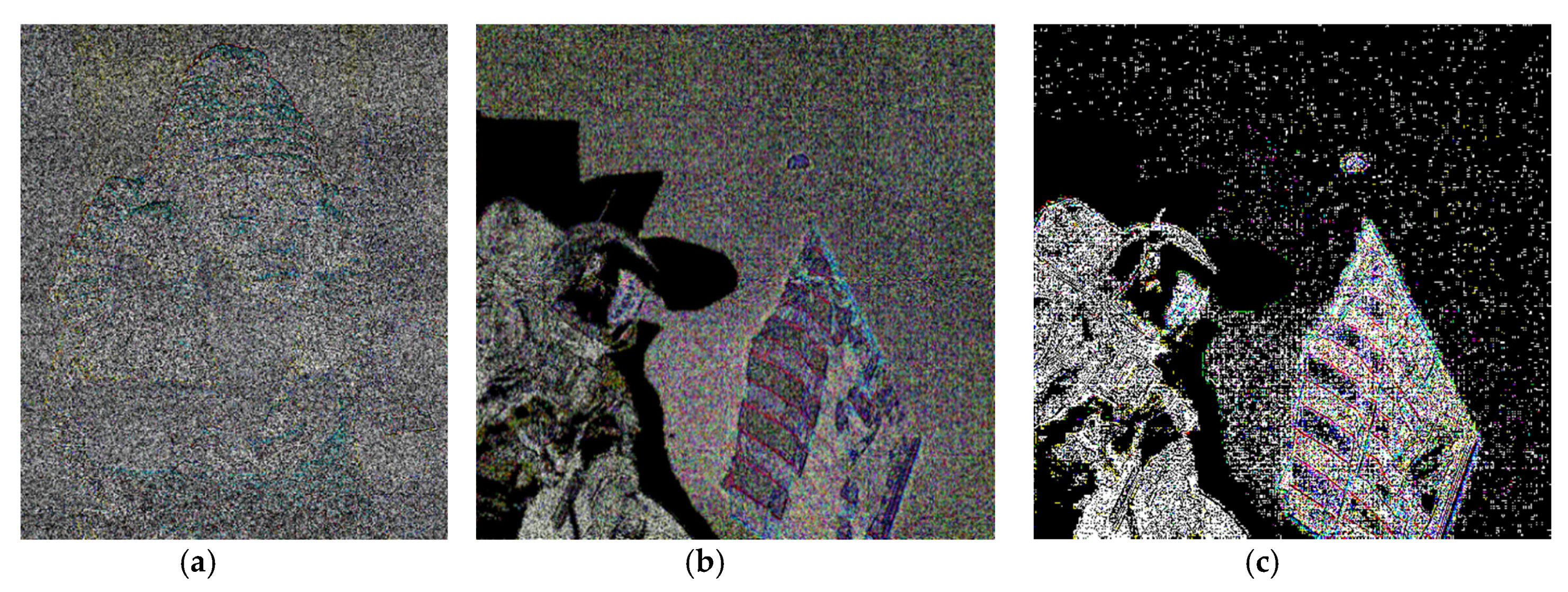
When examining the Wikipedia-commons photo in “Forensically” software, we observe that it was written by Adobe Photoshop 3.0. Comparing the Wikipedia-commons photo with the low-resolution version of the Internet Archive that was published in 1973, we see that it is the same photo. AS17-134-20384 found in the Apollo 17 Image Library (Figure 2) shows that it was written by ZPhotoshop 3.0. Another tool of Forensically examines noise. Image noise covers the whole area of an image in a clear pattern. An example of image uniform noise is shown in Figure 3a, in comparison to the noise inherent in the Wikipedia-commons photo, Figure 3b, and the photo from the Internet Archive, Figure 3c. Photoshop now has the ability to insert uniform noise over an image in order to make it look realistic and, therefore, there is no point in examining the new photo presented in flickr.com.
The analysis shows that GPN-2000-00113 is composed of two main parts separated by a black background with no noise on it. This reasonably leads to the conclusion that the photo was manipulated.
For the record, photographic specialist Jack D. White, BA, also subjected the photo to computer analysis and reached the conclusion that the photo was a probable composite with the sky registering slightly different shades of black density, although it should not [25]. Additionally, Leonid Konovalov, professor of cinematography, after his detailed study, concluded that photo GPN-2000-00113 is a collage of two pictures with a different background: on the left part, a background of black velvet and on the right, a screen made of retroreflective material (scotch-light). Konovalov explains in admirable detail how the collage was produced [26].
3.2. Simulating the Scene at the Landing Site
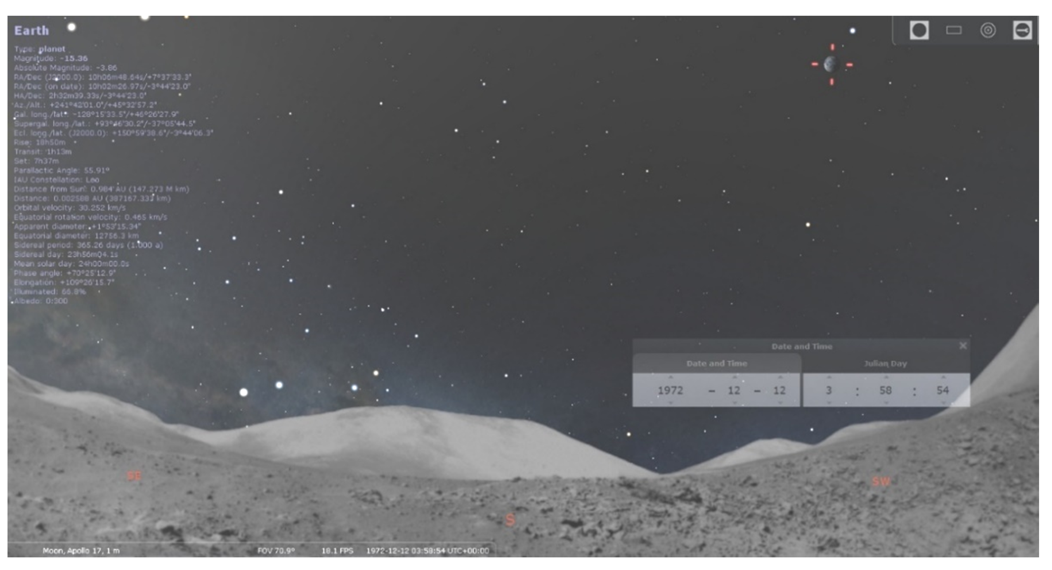
Apollo 17 Image Library [27] gives the information that AS17-134-20384 (the equivalent of photo GPN-2000-00113) was captured at 118:25:54. With the mission of Apollo 17 starting on 7 December 1972, at 05:33:00 GMT [28], this time would be 12 December 1972, at 03:58:54. It is worth mentioning that the above reference also gives the information that the launch of the spacecraft was 2 h and 40 min late due to a ground problem.
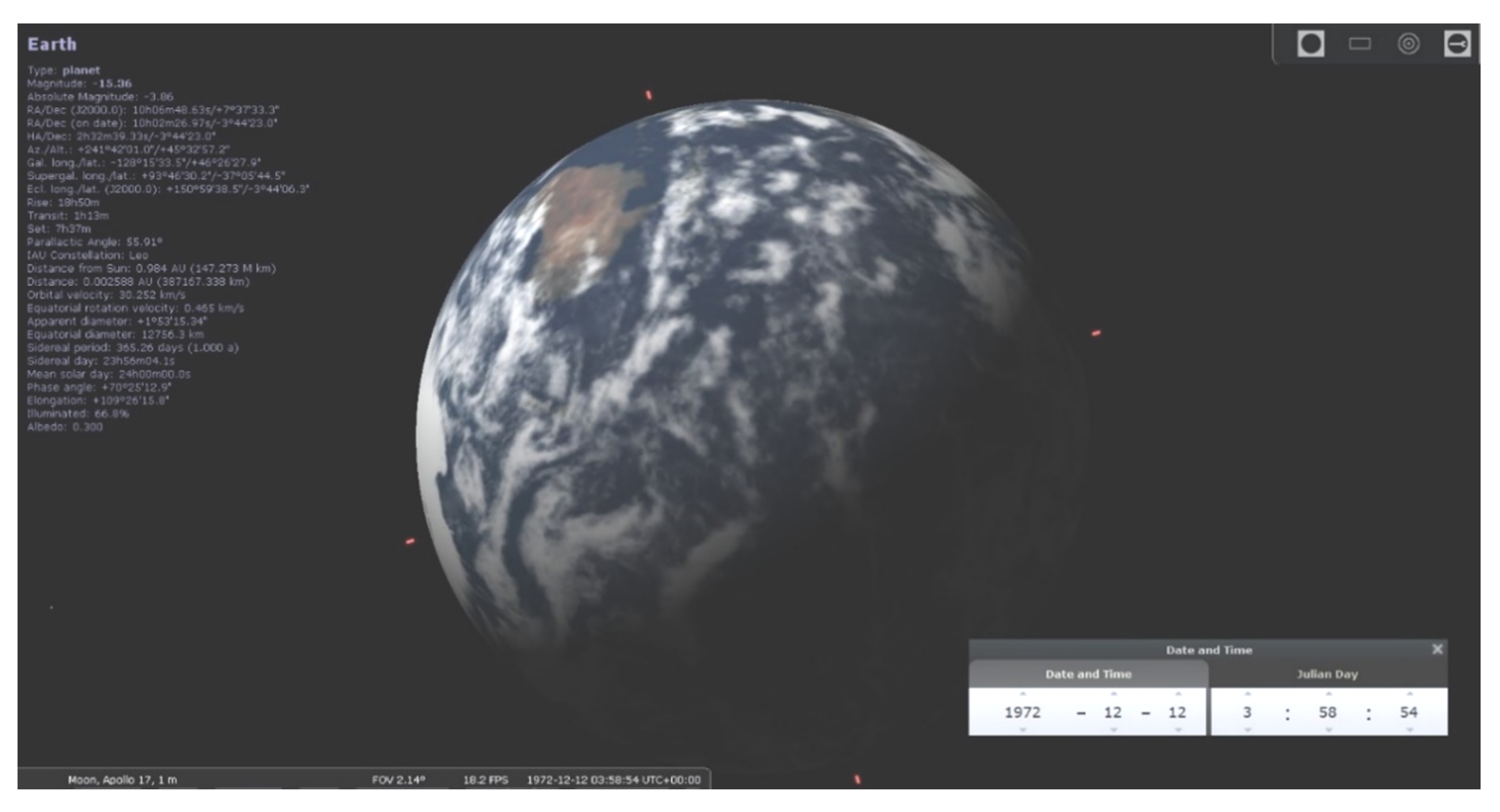
The Stellarium Astronomy software is used to simulate the event, give the position of the Sun and Earth, as shown in Table 1, and present the graphics shown in Figure 4 and Figure 5.
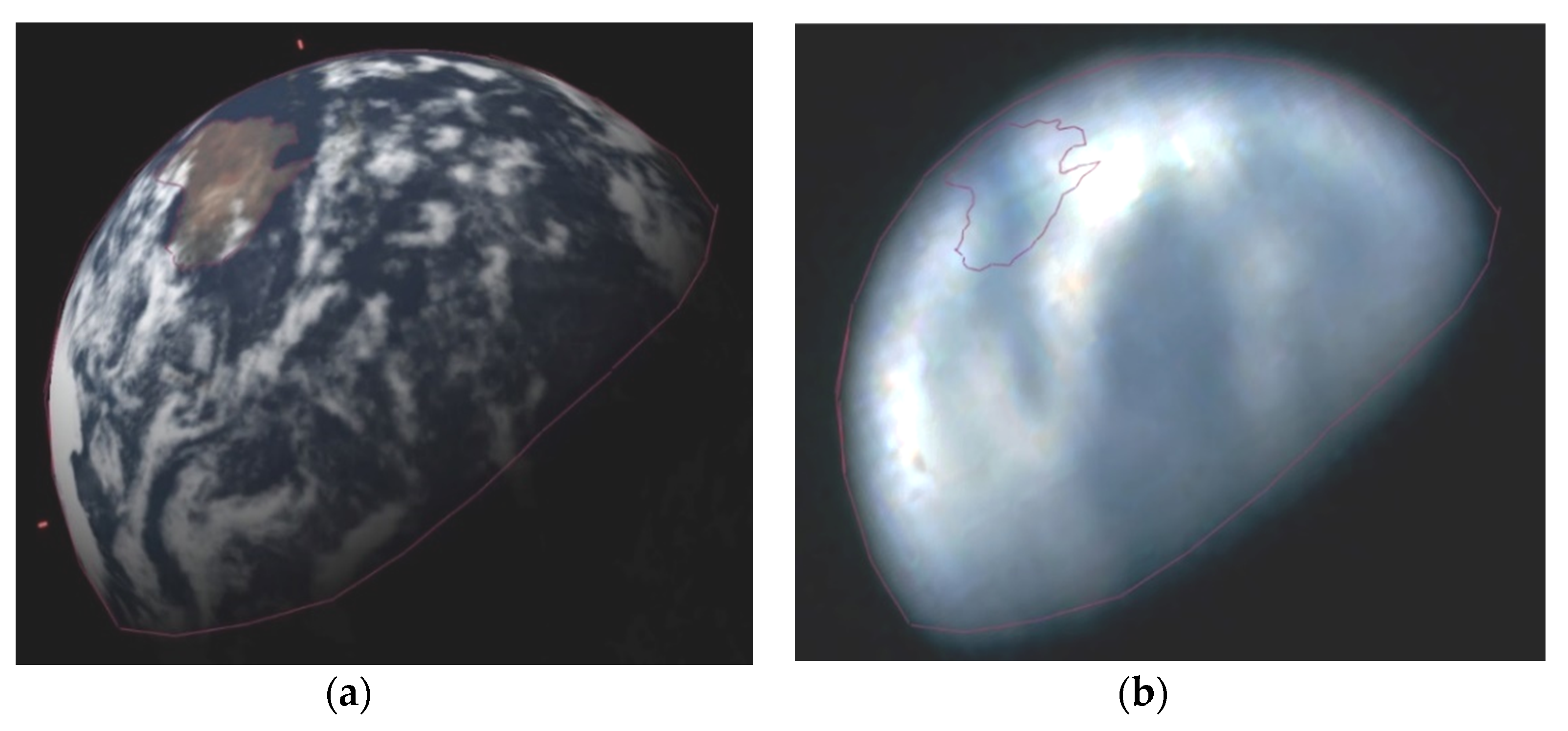
Earth is clearly seen in the photo AS17-134-20384 found in the Apollo 17 Image Library (downloaded in 2016) and permits a comparison of the Earth and its continents as shown in Figure 6.
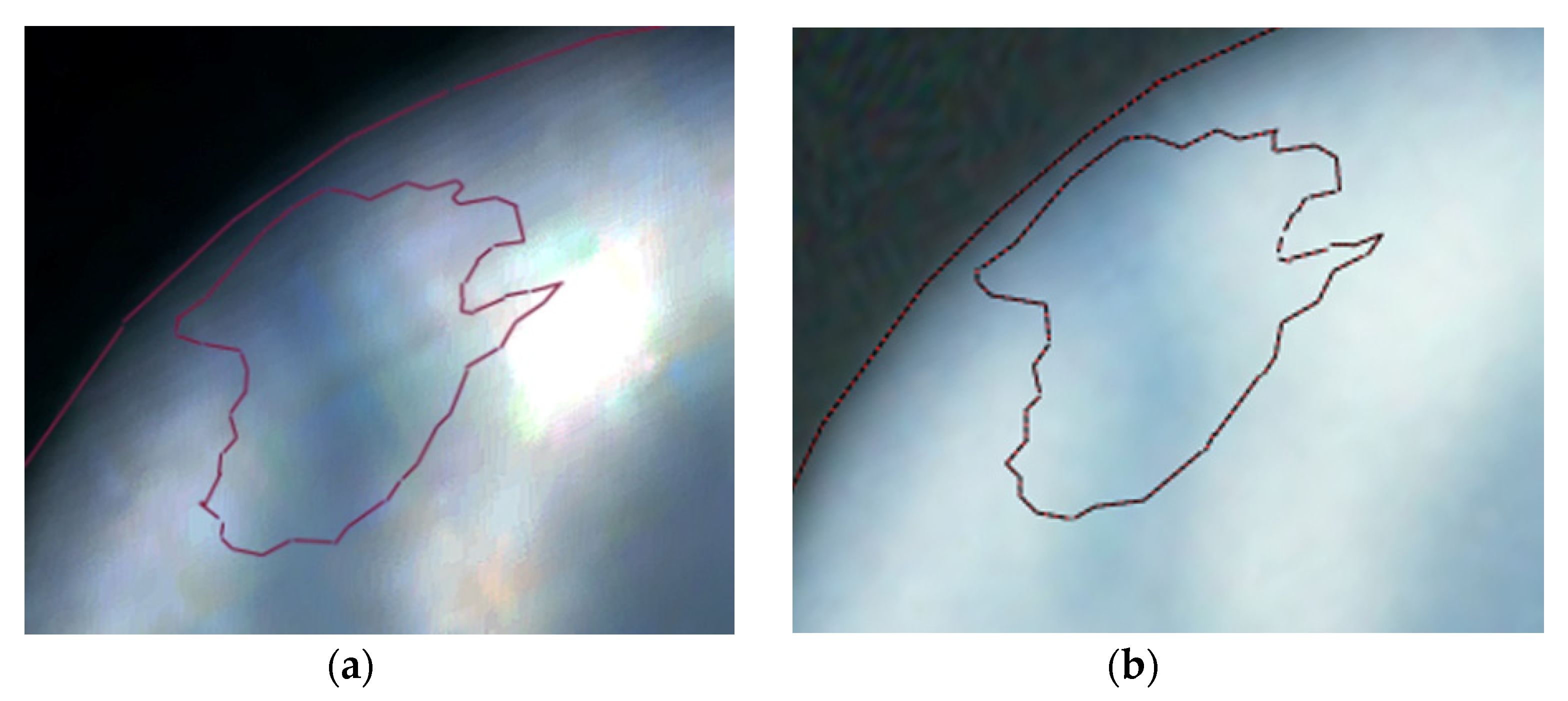
Figure 7 shows an enlargement of where Australia should be in the Earth view from the Moon, as seen in Figure 7a the photo AS17-134-20384; although the cloud cover conceals parts of Australia, it leaves a large amount in the center uncovered but ‘mysteriously’ no land can be recognized underneath. The same observation as above is seen in the new photo scan presented in the photos archived in the NASA commons Flickr account (Figure 7b).
At the time of the Apollo missions, only professionals could fake the above caption, who, in order to present a realistic view at the correct time, should have studied the cloud formation on Earth at the corresponding time. They should have also simulated the Earth view from the Moon location where the astronauts would have taken the photo and made sure that Earth would appear in the photo at the correct altitude and azimuth with the correct phase and size. The book of Paul White [29] titled Clouds Across the Moon: A Comparison of Apollo Mission Photographs with Contemporaneous Satellite Images mentioned that “The ALSJ (Apollo Lunar Surface Journal) gives a specific time for this image as 118:26, which is almost 04:00 GMT. If this were the case, then Australia would be clearly visible. The timeline that has been used so far, however, says that at 04:00 Cernan and Schmitt would have just completed installing the lunar seismic experiment equipment at the ALSEP (Apollo 17 Lunar Seismic Profiling Experiment), not at the flag. The most obvious answer is that the ALSJ is using the GET (Ground Elapsed Time), which is 2 h 40 ahead of the timeline and transcripts. If this time difference is removed from the ALSJ time, we get a time of 01:20 GMT, putting the astronauts exactly where the photograph says they should be (at the flag) and the Earth’s features exactly as they should be”.
We believe that the above explanation has nothing to do with GMT, or local time for that matter, since the ALSJ GET time of 118:26 simply indicates 118:26 h from lift off (i.e., the start of the mission), irrespective of the time system used. We believe that a better explanation is the following: one can assume that the Earth image was staged before the start of the mission for the 118:26 GET with respect to the expected launch time. But as the launch of the spacecraft was unexpectedly delayed for 2 h and 40 min, the actual 118:26 GET did not coincide with the “planned” before the start of the mission 118:26 GET. Hence, the “planned” image of the Earth would be 2 h and 40 min behind the actual time and could not correspond to the correct view.
3.3. Re-Enacting the Caption of Photo GPN-2000-00113
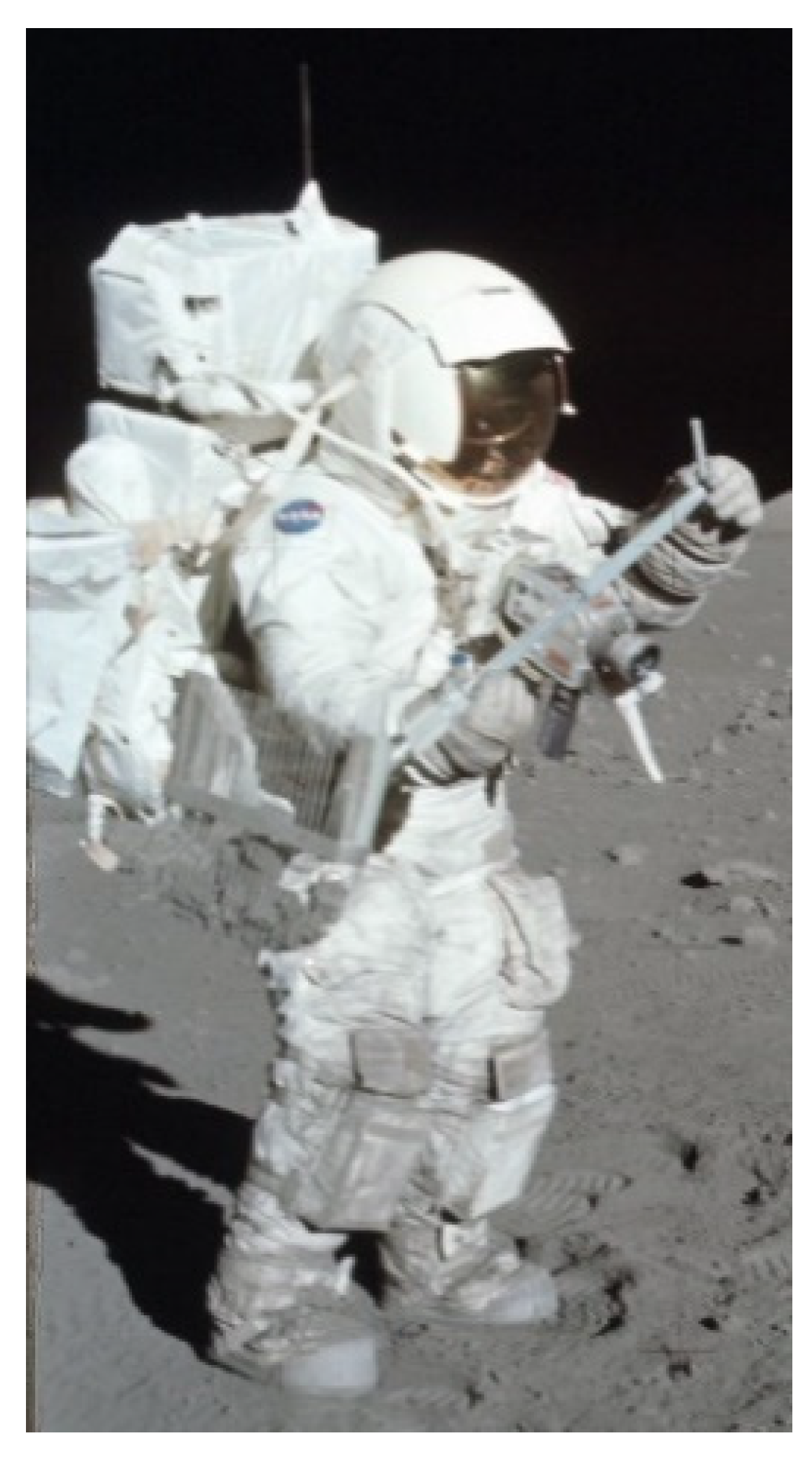
The Apollo astronauts, because it was difficult to handle the camera, had a special chest attachment to hold it while taking photos, as seen in Figure 8.
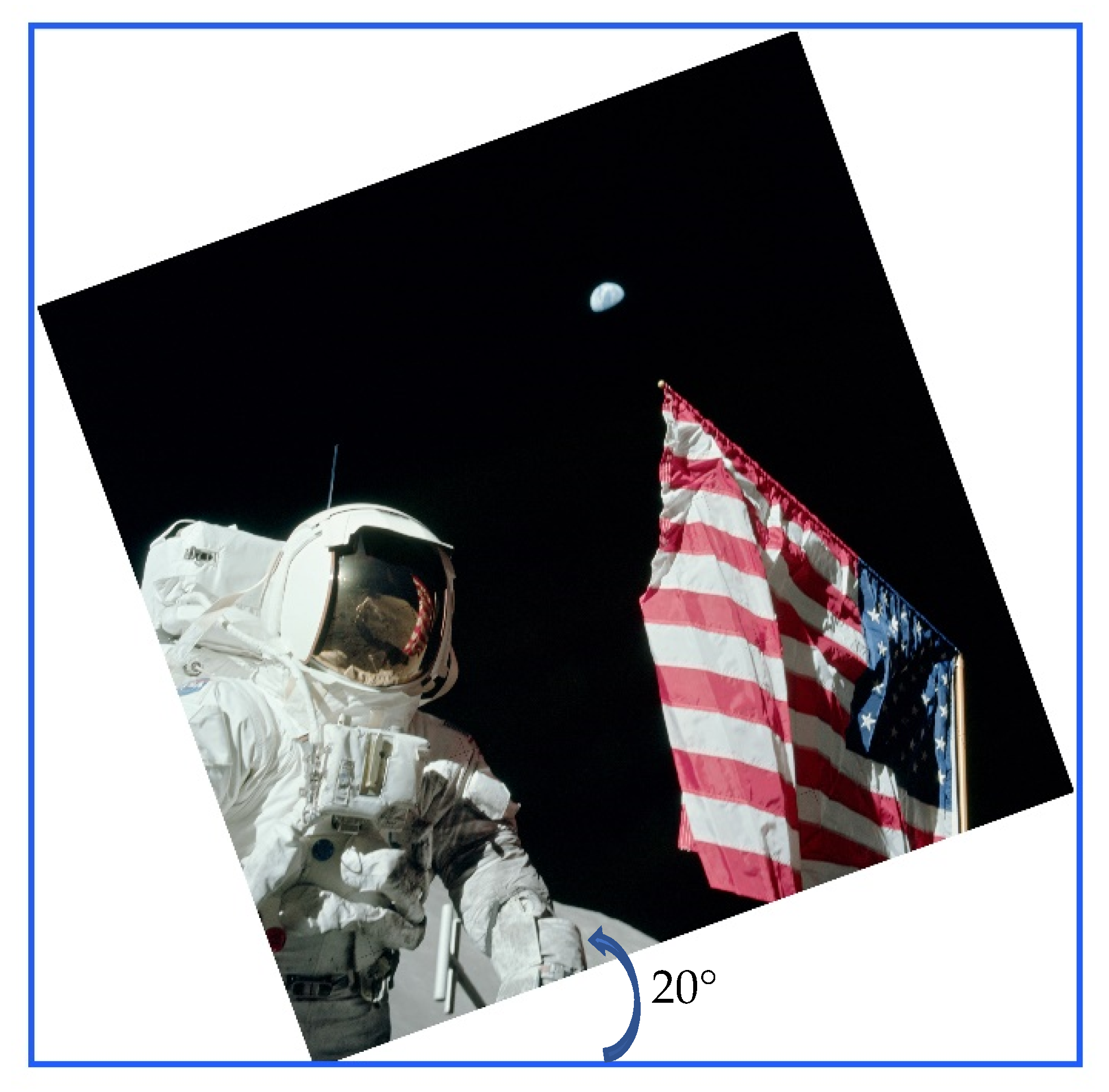
It is obvious that photo AS17-134-20384 could not have been taken by an astronaut-photographer in the vertical position as the flagpole does not appear vertical, but the astronaut had to bend his body to the left at an angle of about 20° to the horizontal, as Figure 9 indicates.
At the time of capture, Earth was at about 45° altitude (Table 1), but in the photo is seen next to the horizontal pole of the flag and the edge of the flag is vertically imaged. This means that the photo was taken from a point near the flag.
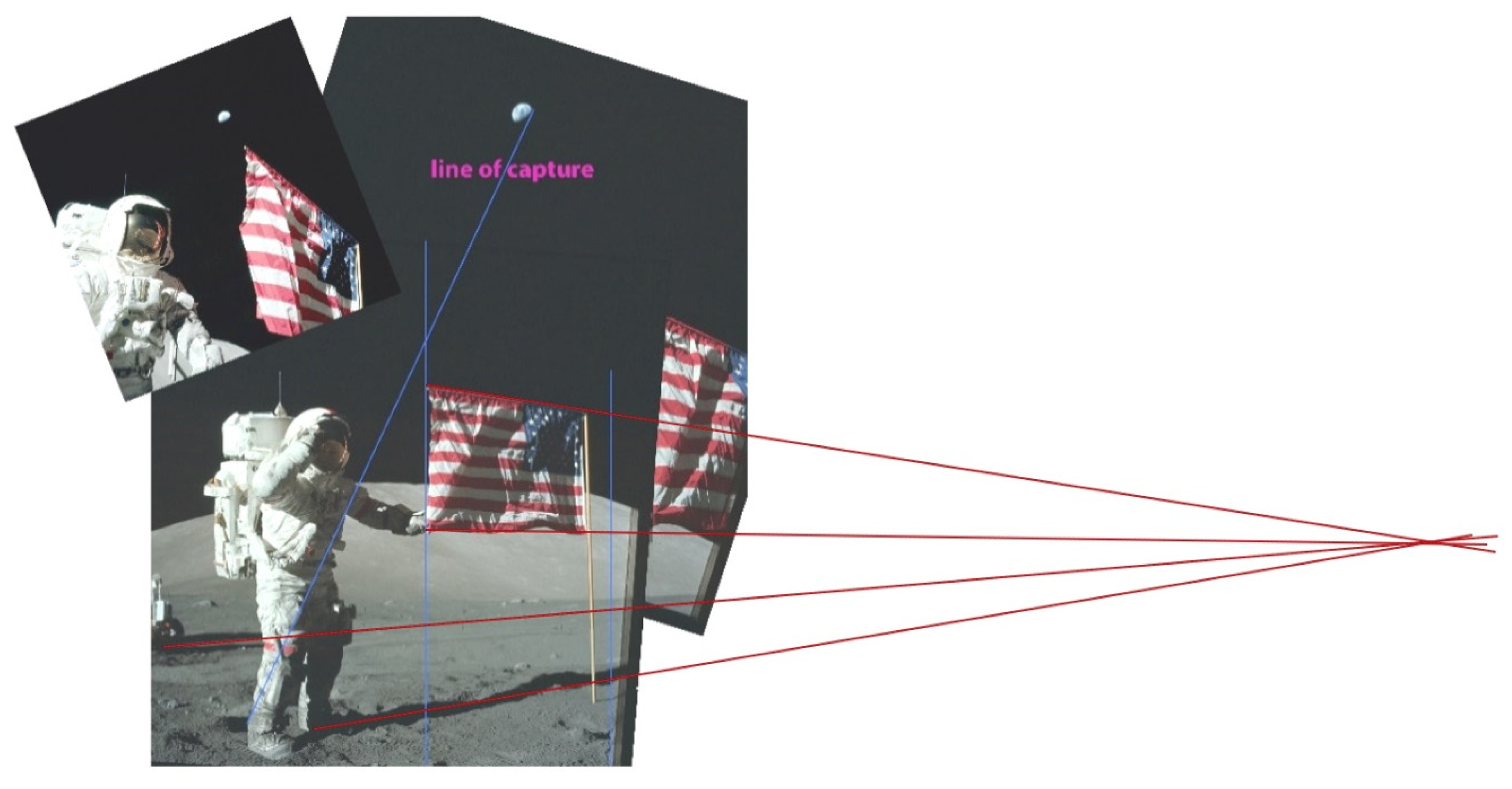
A composite (Figure 10) produced by matching reflections on the background South Massif of photos AS-134-20386 and AS-134-20387 shows the actual position of the Earth relative to the astronauts and the line at which the camera should be in order to capture the scene. Since parallel lines on a photo converge to a point, notice that the shadows are running parallel to the flag’s horizontal length as well, with a few degrees of error.
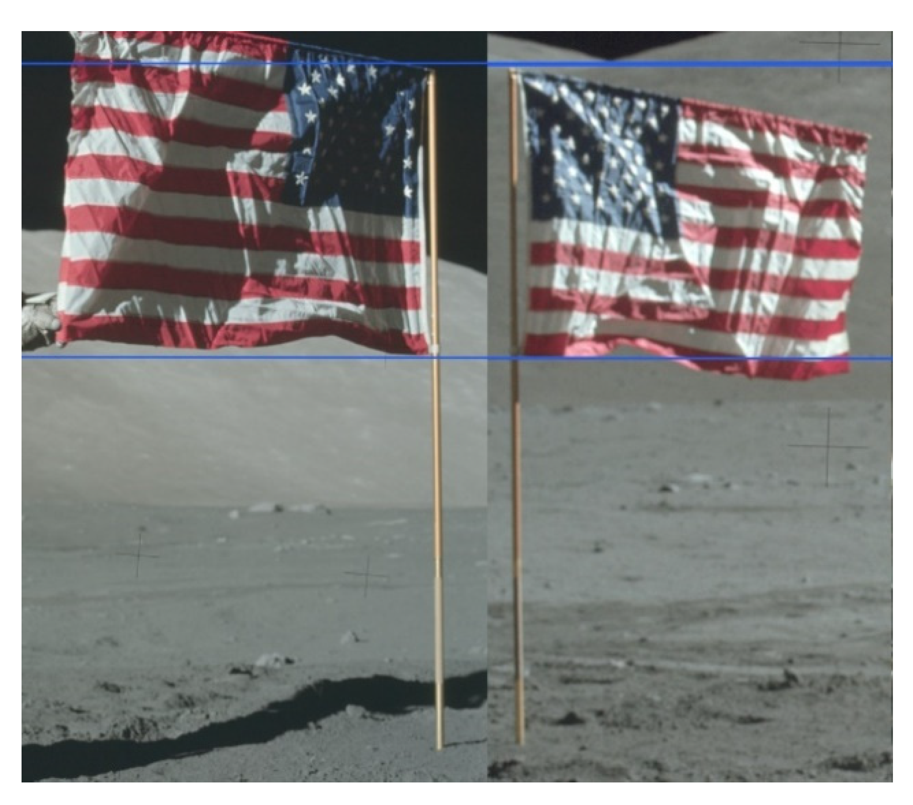
In order to reproduce the scene, some dimensions need to be known, which can be provided by the flag. As mentioned by NASA [31], the Apollo 17 flag was 1.09 m in height by 1.83 m in width. If this was the case, and since photos AS17-134-20386 and AS17-140-21391 image the flag and pole of Apollo 17 (Figure 11), then the height of the pole measured in Photoshop is 2.50 m.
3.4. Checking Heights
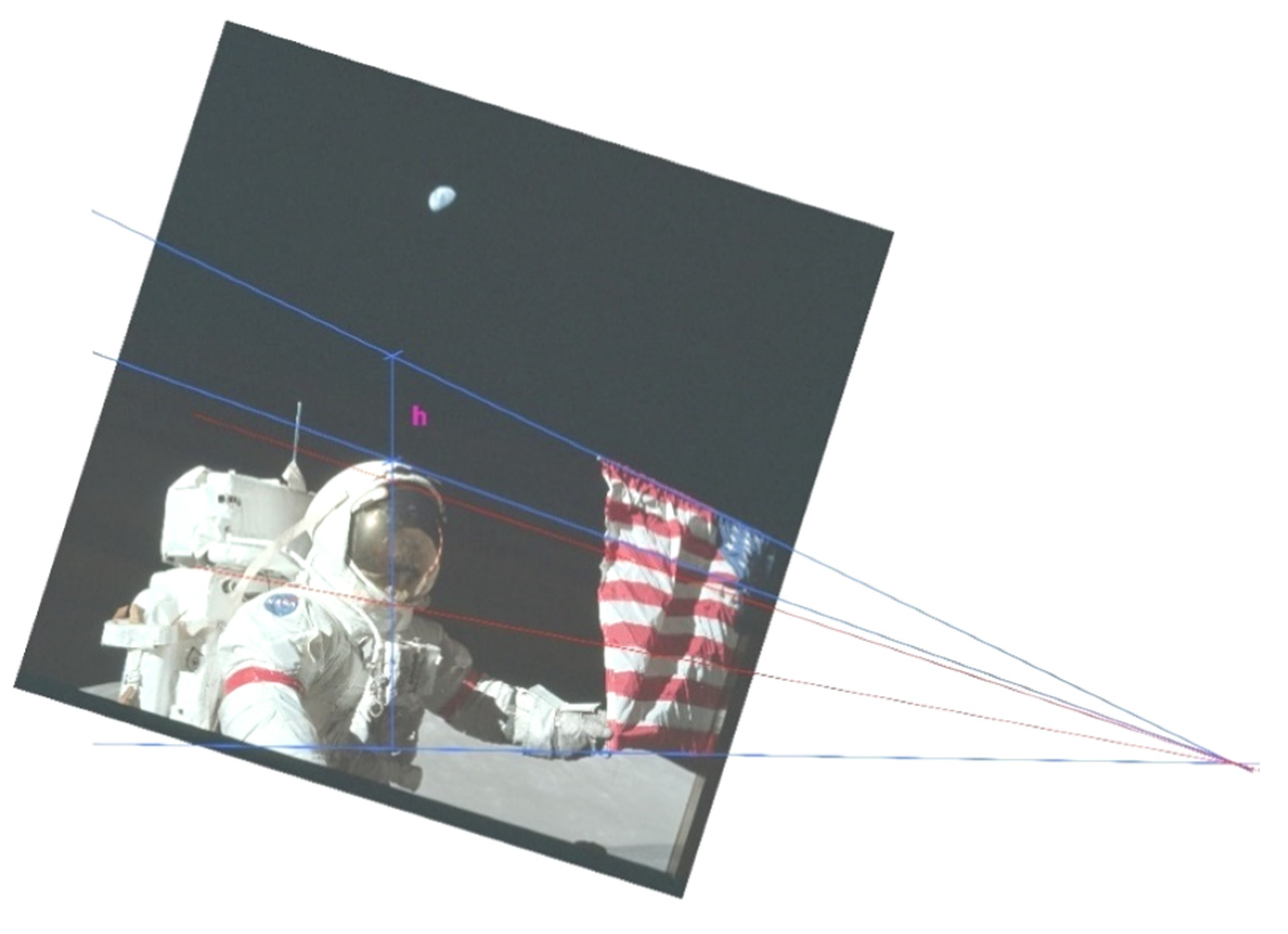
The Apollo AS17-134-20384HR image gives us a good comparison of the relevant heights of the flag and the astronaut, as shown in Figure 12. Since the Apollo 17 flag was 1.09 m in height by 1.83 m in width, and the flagpole stood at 2.5 m high, the astronaut’s helmet top can be estimated with a small error, as the astronaut is just behind the flag line. Measured in Photoshop, distance h is 0.30 m, giving the height of the astronaut to be about 2.2 m. In addition, the glass cover of the helmet is estimated to be 0.36 m (between red lines).
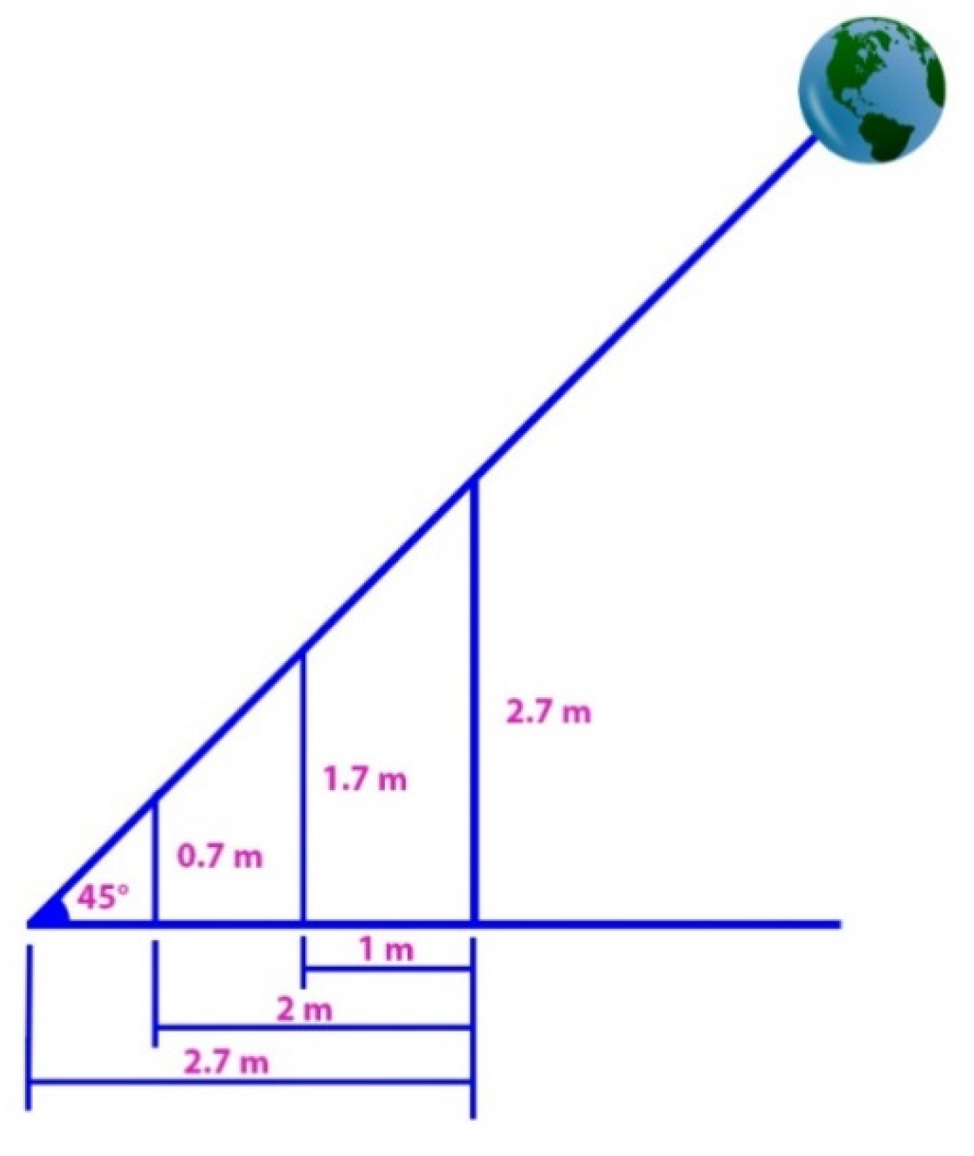
In addition, the apparent height of the Earth above the top end of the flag in photo AS17-134-20384 is measured to be 0.2 m, and as a result is 2.7 m from the ground. Therefore, one could construct the geometry shown in Figure 13.
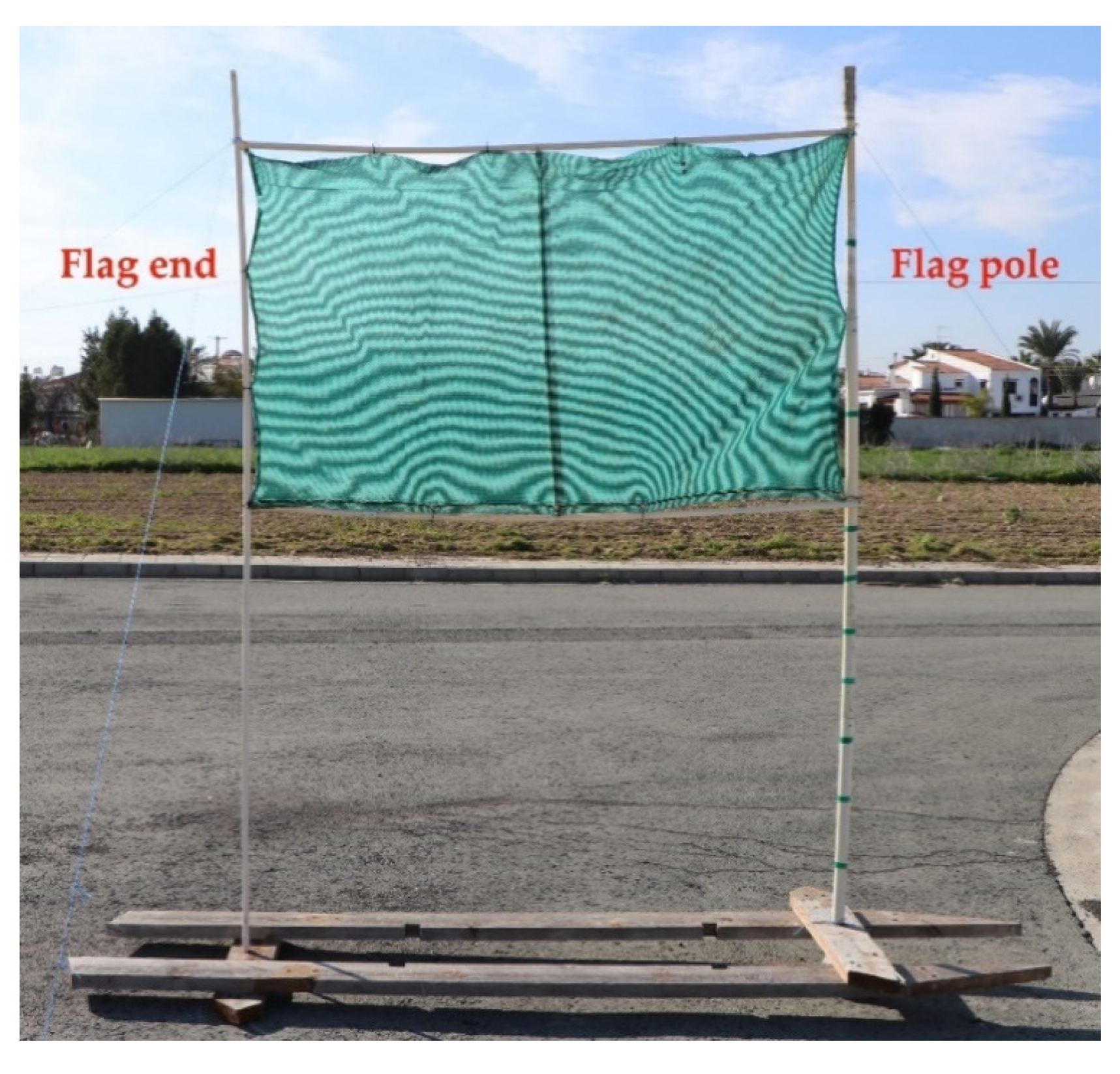
To examine the above findings and reproduce the scene of Figure 9, a pole and a flag at the exact dimensions were constructed (Figure 14) and photographed in the correct angles by replacing the Earth position with the Moon. The photographs were captured when the Moon was at 45° altitude, calculated a priori in Stellarium, for the specific place and time the photographs were taken. The results are shown in Figure 15. This reproduction relies on the apparent position of the Earth relative to the flag top end of its vertical side. The position of the astronaut does not play any role other than to check the field of view (the angle through which light is recorded) of the camera used.
The focal length of the lens used on the Hasselblad camera is of interest for the comparison because of its field of view. This piece of information was given by the Lunar and Planetary Institute [32], which mentions that the camera used above was equipped with a 60 mm lens (LM1). The focal length of the lens affects the capture angle. A smaller focal length will capture through a wider angle (greater field of view). In addition, with a greater focal length, one can see a greater image of an object. The Hasselblad camera used a 70 mm wide photographic film with a frame size of 53 mm × 53 mm (diagonal of the frame 75 mm). The angle (α) of the image field is determined by the formula
where d is the diagonal of the frame and f is the focal length of the lens [33]. Then, the angle of coverage of the lens of the Hasselblad camera was 64° (a wide-angle lens).
α = 2arctan(d/(2f))
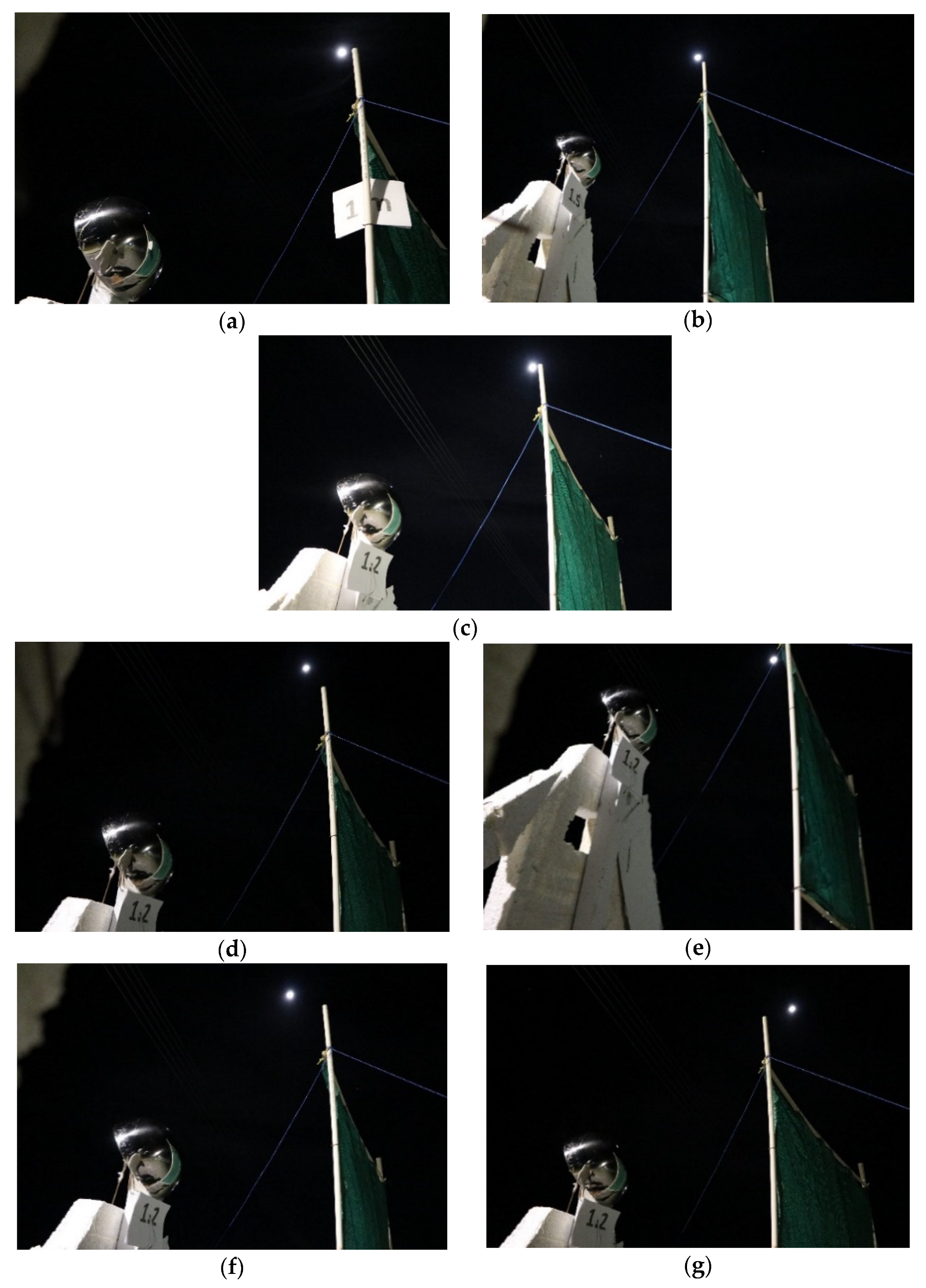
For the reproduction scene, a Canon 80D camera was used, fitted with the Canon EF-S 18–135 mm lens that was set to 22 mm. The specific camera has a 22.3 mm × 14.9 mm CMOS (complementary metal oxide semiconductor), resulting in images of 6000 × 4000 pixels. Substituting the above values into formula (1), we get a 63° angle of lens coverage. Images a through c of Figure 15 can capture the position of the Earth (represented by the Moon), astronaut, and flag in the positions imaged in AS17-134-20384. Because the image field angle of the reproduction is essentially the same with the actual Hasselblad camera, relative sizes can be compared. This leads us to conclude that the photographer was standing at about 1.2 m away from the flag end and taking the photo from chest height (about 1.5 m height).
The relative position of the Earth (represented by the Moon in the reproductions) is shown in the correct height from the top end of the flag. If the photographer moves further upward from the correct line of view (see Figure 10), then the Earth should be imaged at a higher point from the flag end, as shown (by the position of the Moon) in Figure 15d. Correspondingly, at a lower height, Earth should be imaged at a lower point, as seen in Figure 15e. A position further to the left would move the Earth position in the image to the left (Figure 15f), and a position further to the right would move the Earth position to the right (Figure 15g).
Based on the angle of image field of 64° (see Equation (1)) and considering that the distance from the flag end of the photographer had to be 1.2 m, as explained above, it would be impossible to capture the correct position of the Earth (with an altitude angle of about 45°) in a lower position than 1.5 m.
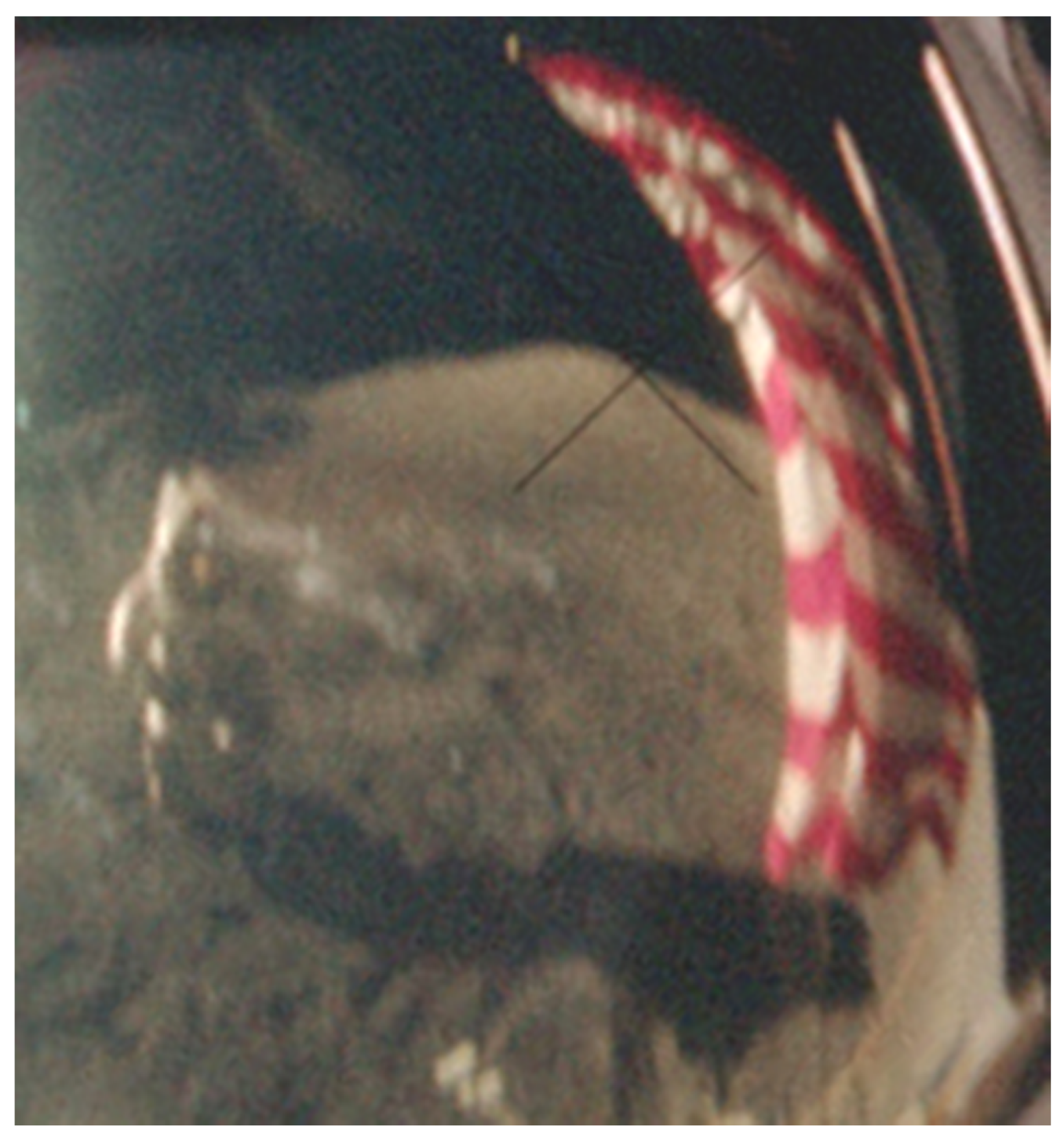
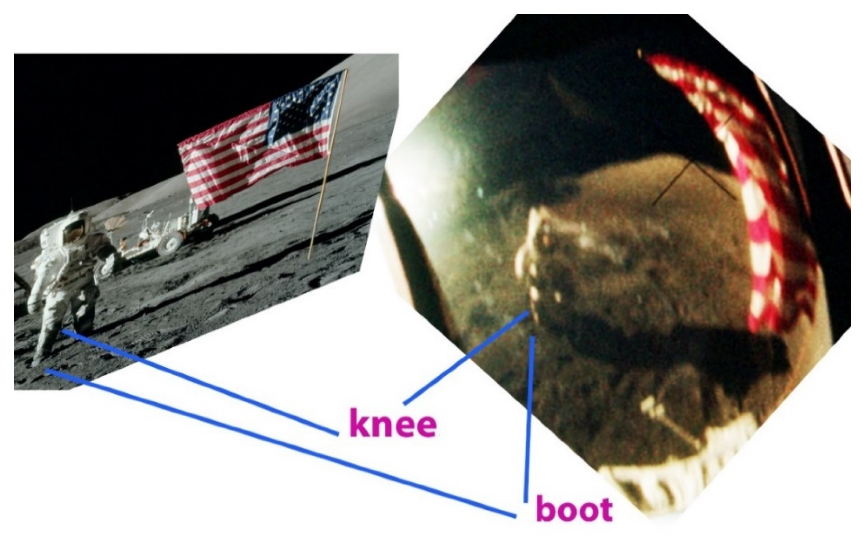
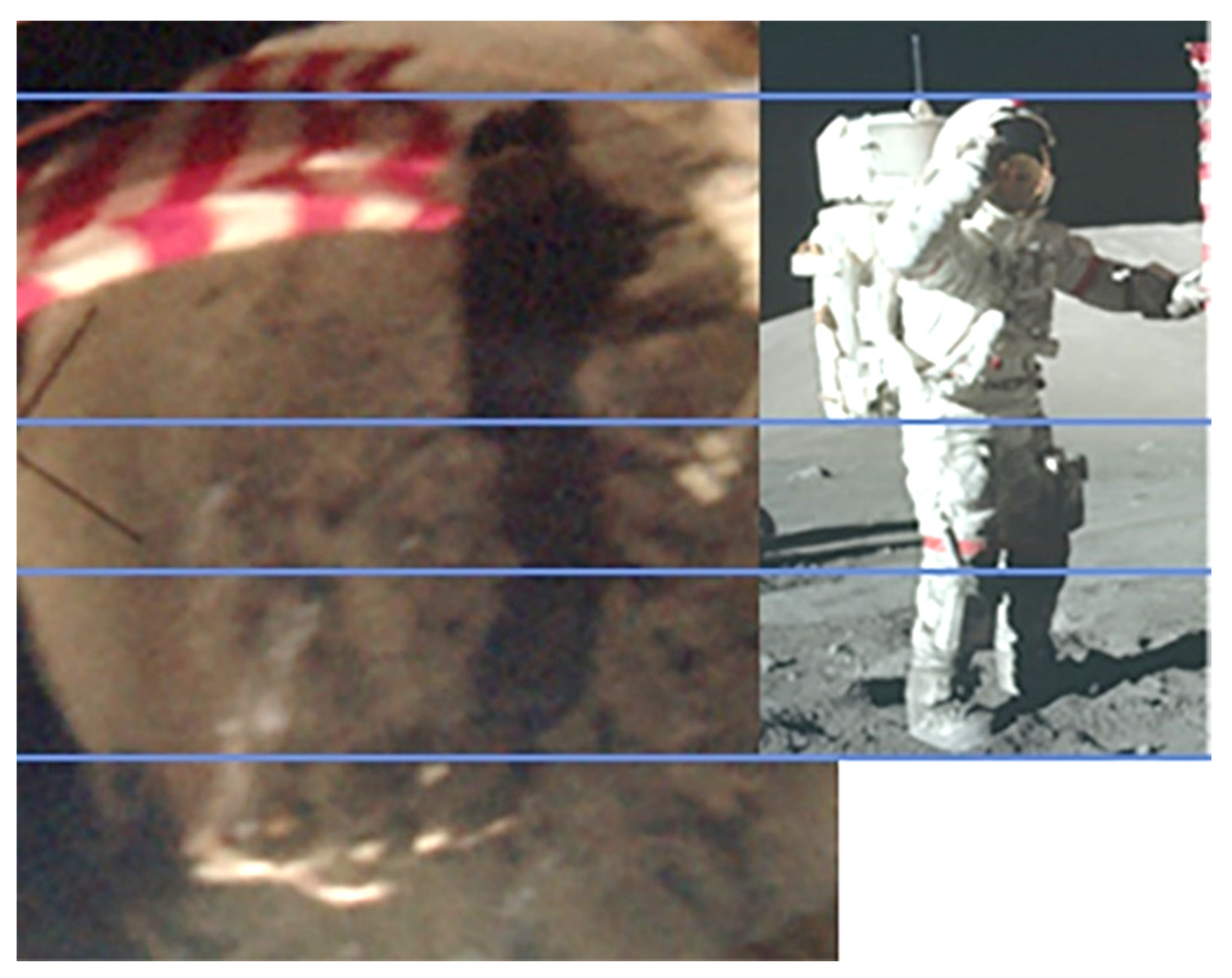
The reflection on the helmet (Figure 16) can provide more information. Because of the low angle of the Sun, the shadow length for an astronaut of 2.2 m height is large, namely 7.1 m for 17° altitude (see Table 1). Therefore, the photo shows that it was taken at least 5.5 m distance from the flagpole. Figure 16 shows that the astronaut is standing, since otherwise his leg and feet (from the knees downwards) should make a 90° angle to the body backwards and positioned on the ground, but these are not shown. To verify the above observations, the shadow of the astronaut can also be compared to his view in the spacesuit, as indicated in Figure 17. The corresponding lines in Figure 18 do not leave any doubt that the astronaut is in a standing position.
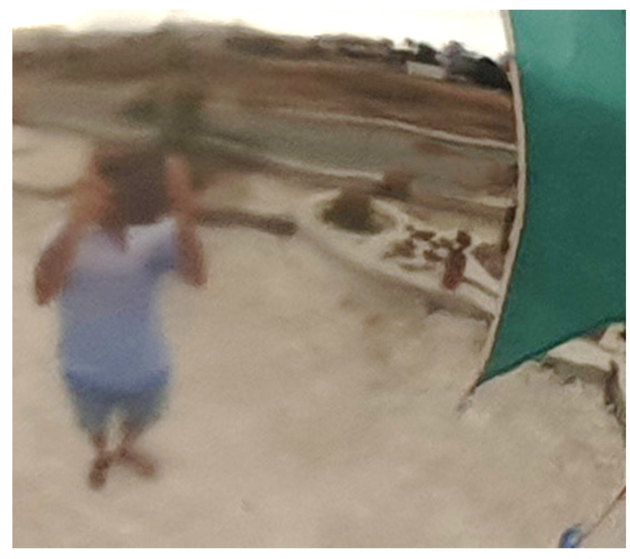
In AS17-134-20381HR and all other related images, the shadow of the astronaut is imaged running parallel to the flag’s width, while in the helmet reflection the shadow seems to be at 90° to it. In addition, the astronaut in the reflection looks as if he is viewed from above. Both these impressions are illusions created by the convex surface of the screen on which the reflection is created. The image in a convex mirror shows the top parts of the body as more elongated than the lower ones, which are shown to be compressed (see Figure 19).
3.5. Reproduction of the Scene Reflected on the Helmet
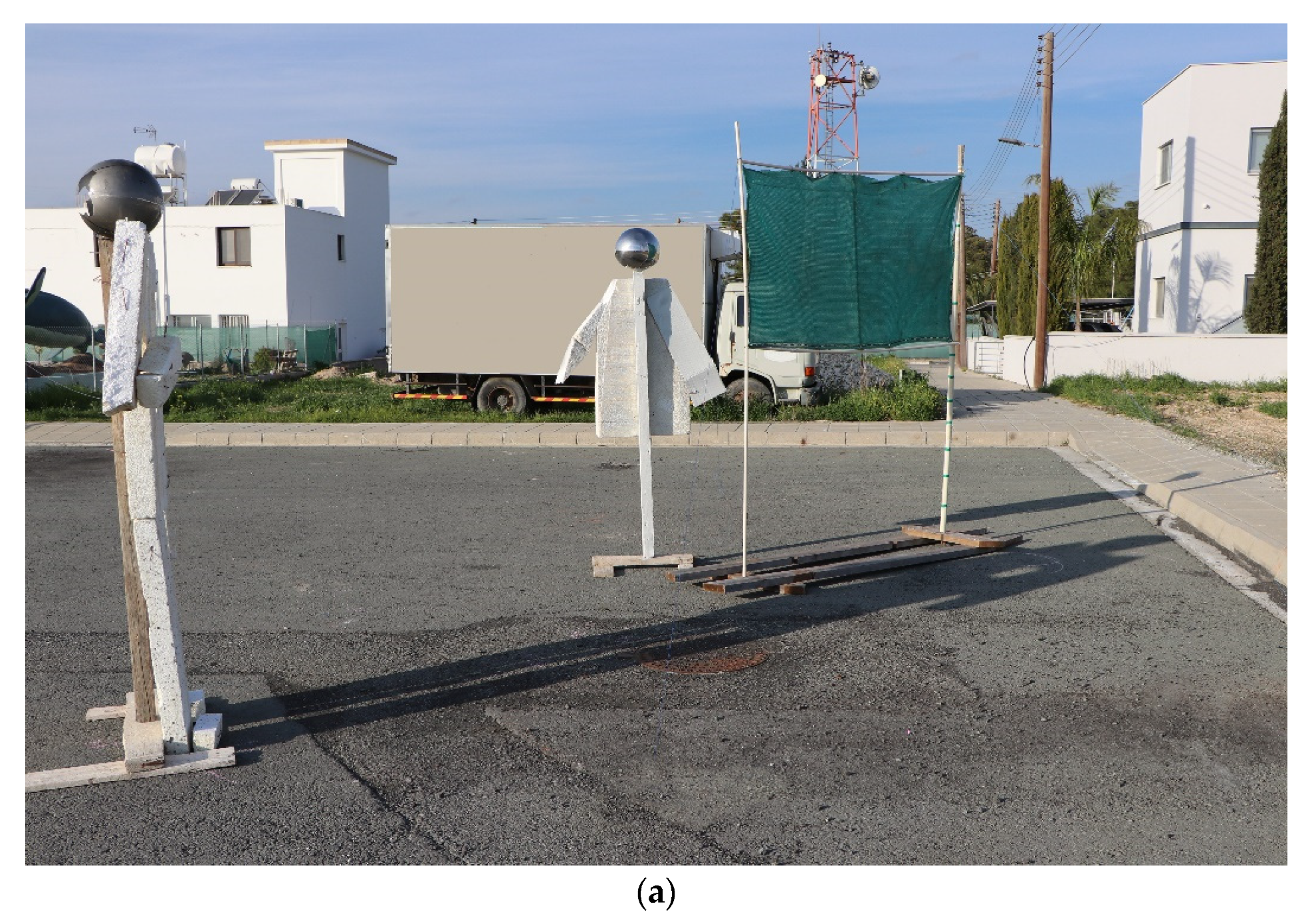
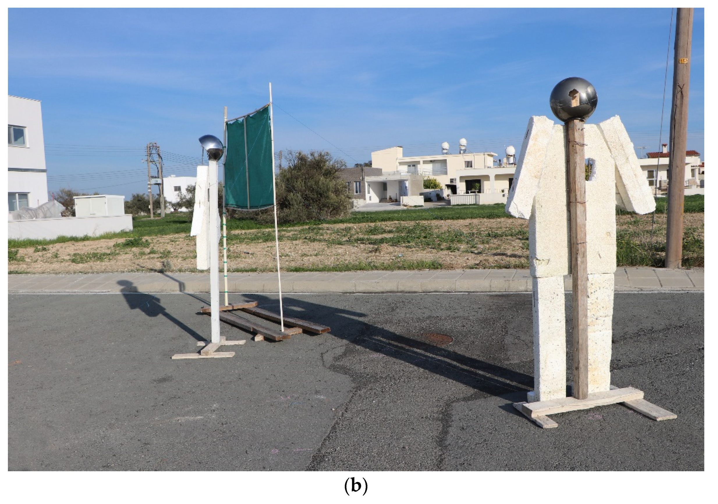
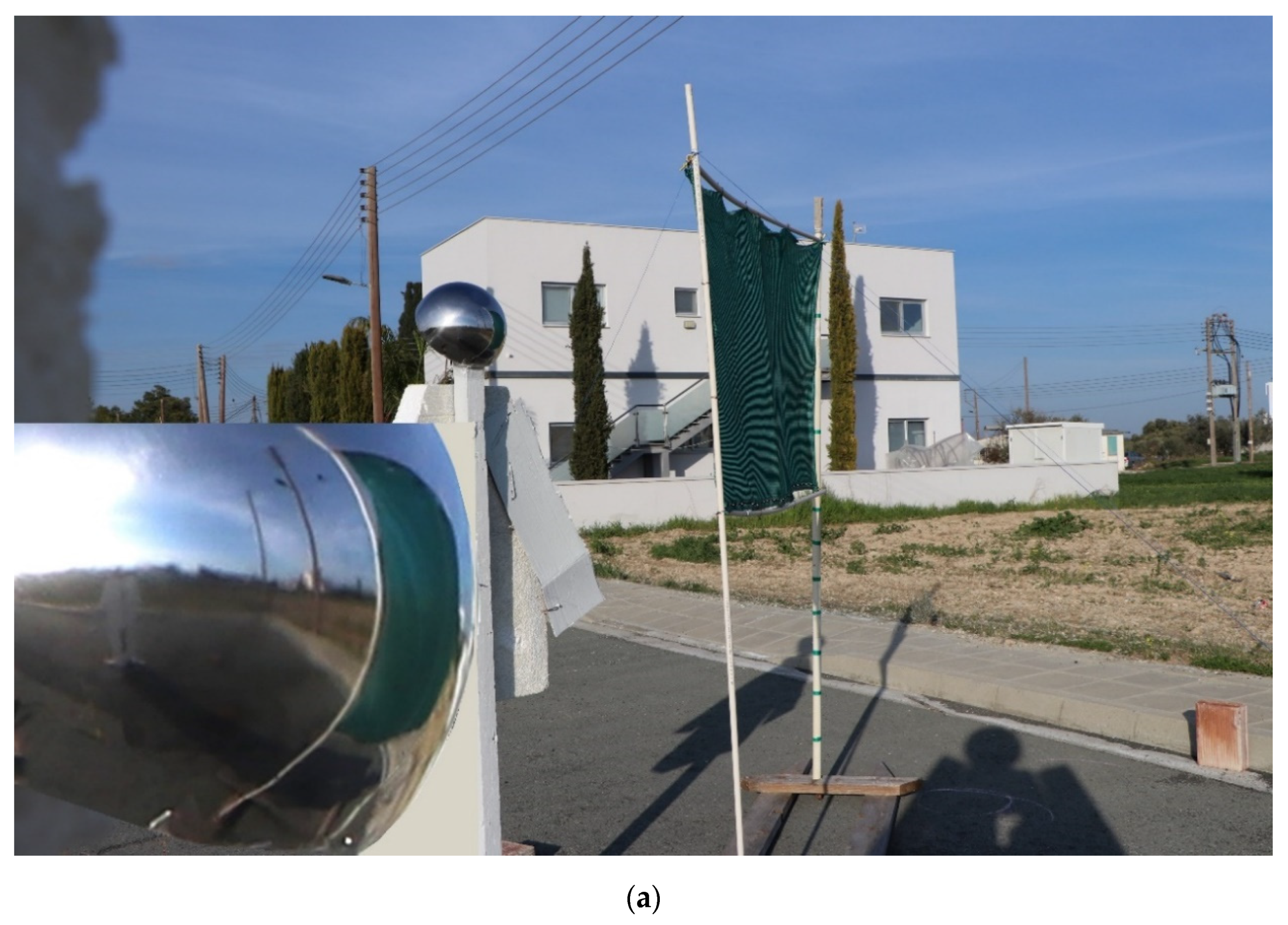
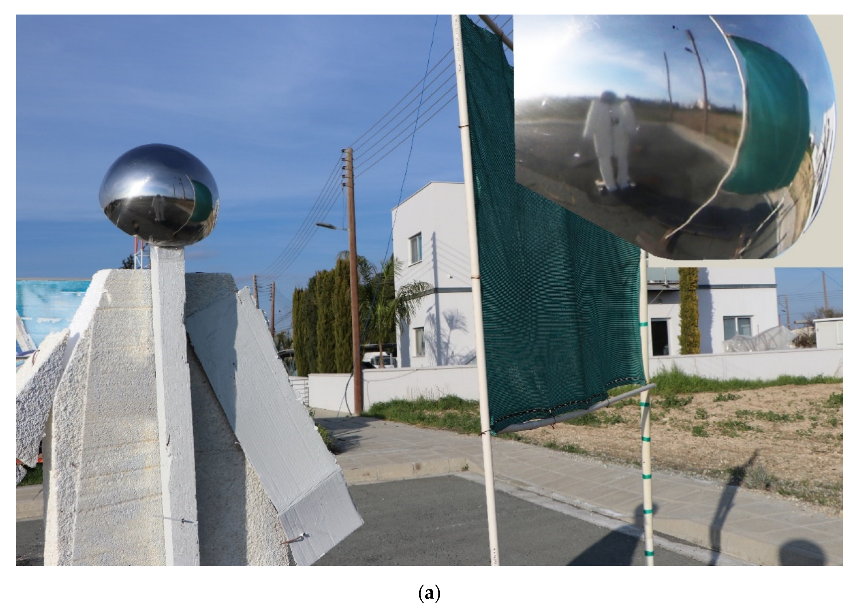
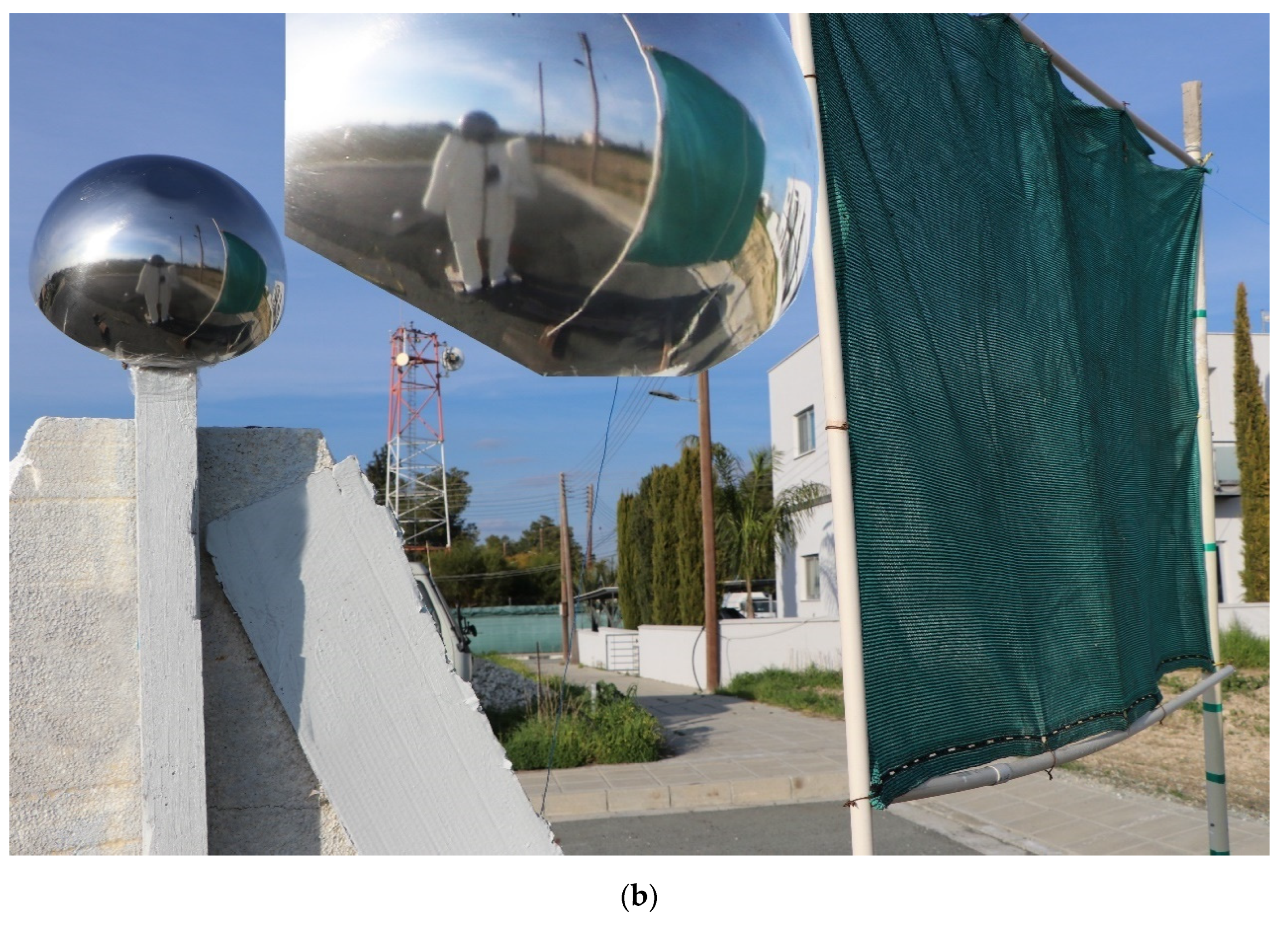
For the reproduced scene, the flag with a 2.5 m pole was positioned relative to the Sun in such a way as to have the shadows running parallel to the flag length. The flagpole is represented with the thicker pipe with the green stripes. A spherical (convex) mirror of 0.29 m diameter, representing the astronaut’s helmet, was fixed on a pole to reach a height of 2.2 m, while a polystyrene board astronaut of 2.2 m height was placed at 5.5 m away from the flagpole (for the reason explained above) (Figure 20).
The photographs were captured when the Sun was at 17° altitude, calculated a priori in Stellarium, for the place and time in reference. The polystyrene board astronaut was moved to or away from the flagpole until the mirror reflection of the position of its shadow in relation to the flagpole matched the reflection in the helmet (Figure 21 and Figure 22). This is very crucial, because the point to which the shadow of the polystyrene board astronaut reaches in relation to the flagpole indicates the distance of the astronaut taking the photo. Consequently, the distance from the flag end was found to be about 3.5 m, on the line running along the length of the flag (for a topographic presentation of the exact points, see also Section 3.6 and Figure 25 therein).
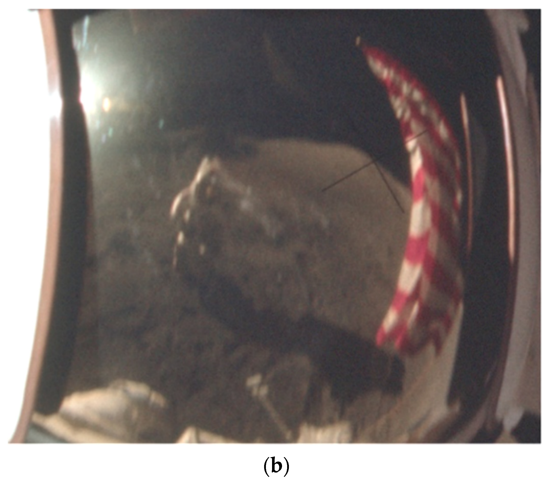
A comparison of the reproduction of the helmet reflection also shows that the shadow in the reproduction (Figure 22a) is much longer than the one shown in the screen of the helmet (Figure 22b, indicating a possible manipulation of the image in the screen of the helmet. This agrees with and verifies the findings of the photographic analysis shown in Figure 3 and Konovalov [26], who showed that the reflection of the flag on the helmet is a collage on the left part of the image.
If the astronaut, when taking the photo, was standing near the line of capture indicated by the position of the Earth in the photo (see Figure 10), his shadow would go beyond the pole in the reflection of the helmet. Such cases, shown in Figure 23, are reproduced to prove the case.
Furthermore, we examined if the shadow and flagpole distance are sensitive to the type of convex mirror used and if the radius of the mirror affects the way the shadow position is imaged. For this case, a false shadow (helmet and shoulders) was drawn on cardboard and placed on the ground, next to the flagpole as it should have been had the astronaut been standing at 5.5 m away from the pole at the correct time (Figure 24). All examined cases show very similar images without leaving any doubt about the relative positions of the objects.
3.6. Summary of Results
Summarizing, the analysis above produced two separate representations. In the first one, the Earth’s position at the time of the image capture was represented by the Moon when it was at the correct altitude angle, and a polystyrene board astronaut was placed at an arm’s length from the flag end. This presentation showed that the camera was about 1.5 m above ground level with the camera affixed to the chest bracket of the space suit and at 1.2 m distance from the flag end (Figure 15). The second representation used the astronaut’s shadow when the Sun was at the right altitude in relation to the flagpole to locate the point where the astronaut was standing according to the reflection on the helmet screen. This distance was estimated to be 6 m from the flagpole (Figure 20 and Figure 21). The above results are presented in Figure 25, showing the astronaut position taking the photo estimated by the position of the Earth in the photo (blue mark) and by the position of the astronaut’s shadow on the screen reflection of the helmet (red mark). One can clearly see the large mismatch between the two marks, leading to the conclusion that the reflection in the helmet is a collage.
4. Error Estimation of Dimensions
Some of the distances calculated may not correspond to actual ones due to inaccuracies in estimation. For example, in Section 3.5, the height of the astronaut was estimated to be about 2.20 m. The actual height of astronaut Gene Cernan imaged in AS17-134-20387 was 183 cm (6 feet, given in [34]). One should add to this height, the height of the helmet assemblies, which is about 12 cm, the height of the sole of the pressurized suit (about 2 cm) and the thickness of the lunar boots (about 3 cm), bringing the total height to about 200 cm (for equipment height estimation, see also [35]). Estimations of astronaut Cernan’s heights as imaged in various photos of the same scene are shown in Table 2. The height varies from 2.12 to 2.20 m and is close to the actual one of 2.00 m, showing a minimum error of 6%. This difference has no effect on the estimation of the distance of the camera from the pole (see Figure 13), but a difference in the flagpole height will affect the estimation. The pole height is estimated between 2.40 and 2.50 m. Clearly, the error in the estimation of the pole height (whichever is the correct one) is negligible, due to the fact that the pole and the end of the flag are on the same line. Assuming that the Earth is 0.2 m above the flagpole (based on the estimation from photo AS17-134-20384, Section 3), the Earth is seen at a height between 2.6 and 2.7 m. Therefore, the distance of the camera from the pole in the former case and for a camera height as before of 1.5 m will be 1.1 m instead of the calculated 1.2 m (for the 2.7 m case).
As mentioned above, photo AS17-134-20384 shows a portrait of Harrison Schmitt with the U.S. flag and the Earth. The photographer, therefore, throwing his shadow on the scene and depicted in the helmet screen is Cernan, with an actual estimated height of 2.00 m. For this height, with the sun angles (see Table 1) of +17°29′58.2″, the shadow length would be 6.3 m instead of 7 m (for a 2.20 m astronaut height). The distance, therefore, of the photographer to the flag end would be about 2.8 m instead of about 3.5 m, with no significant effects on our conclusions.
Now, could the flag photographed in the staging be normal in size (92 cm × 153 cm) and not oversized by 20% (see Section 3.5)? In this case, the measured height on the photos of the depicted astronaut falls well below the estimated height of astronaut Cernan, making no sense unless a shorter “stage” man was used instead.
5. Conclusions
A simple forensic analysis of the data locked in the “retired” photo GPN-2000-00113 can show that it was not a real photo, but it was composed of different parts. Although the photo is now replaced with a new version in which the editing errors have been corrected, the geometrical mismatches cannot meet reality.
Because the exact time and place on the Moon at which the photo was taken is known, a simulation software was used to reproduce the view of the Earth. It was shown that the photo of the Earth was missing Australia, obviously because the launch of the spacecraft was delayed by 2 h and 40 min, and hence the a priori staged photo of the Earth could not correspond to its correct view.
Experimentally—through a reproduction of the photo—it was shown that the astronaut-photographer was most probably standing with the camera 1.5 m above ground level and at 1.2 m distance from the flag end. This reproduction relies on the apparent position of the Earth relative to the flag top end of its vertical side. The helmet reflection, on the other hand, allows an estimate of the distance of the astronaut taking the photo from the flag end to be about 3.5 m, depending on the Sun angle. The estimation is based on the crucial point the shadow of the polystyrene board astronaut reaches in relation to the flagpole.
Because of the geometrical mismatches, it was concluded that the reflection on the helmet is a collage, which is in line with the performed software analysis indicating the same result. Therefore, the new photo AS17-134-20384 that has replaced GPN-2000-00113 will always show the effect of the geometrical mismatches, although now no visible traces of the collage can be shown, which must have been removed and corrected by a modern software.
The above analysis shows that in the specific reel of film, there is a photo that casts aspersions onto the reality of the space mission as presented to the public by the photographic evidence.
Author Contributions
Both authors (P.A., P.C.) contributed equally in all aspects of this work. Both authors have read and agreed to the published version of the manuscript.
Funding
This research received no external funding.
Conflicts of Interest
The authors declare no conflict of interest.
References
- Fiete, R.D. Photo Fakery, Oemagazine 2005. Available online: https://spie.org/news/photo-fakery?SSO=1 (accessed on 11 December 2020).
- Lefley, C. Seeing is believing: The capacity of the manipulated photograph to represent scenes of mythology and the supernatural. In Deception: An Interdisciplinary Exploration; Brill: Leiden, The Netherlands, 2015; pp. 115–126. [Google Scholar]
- Edgerton, H.E. Transparency Photographic Apparatus. U.S. Patent No. 3,065,667, 27 November 1962. [Google Scholar]
- Thomson, T.J.; Angus, D.; Dootson, P.; Hurcombe, E.; Smith, A. Visual Mis/disinformation in Journalism and Public Communications: Current Verification Practices, Challenges, and Future Opportunities. J. Pract. 2020, 1–25. [Google Scholar] [CrossRef]
- Abdel-Basset, M.; Manogaran, G.; Fakhry, A.E.; El-Henawy, I. 2-Levels of clustering strategy to detect and locate copy-move forgery in digital images. Multimed. Tools Appl. 2020, 79, 5419–5437. [Google Scholar] [CrossRef]
- Othman, P.S.; Ihsan, R.R.; Marqas, R.B.; Almufti, S.M. Image Processing Techniques for Identifying Impostor Documents Through Digital Forensic Examination. Image Process. Tech. 2020, 62, 1781–1794. [Google Scholar]
- Salih, Y.; Malik, A.S. Depth and geometry from a single 2d image using triangulation. In Proceedings of the IEEE International Conference on Multimedia and Expo Workshops, Melbourne, VIC, Australia, 9–13 July 2012; pp. 511–515. [Google Scholar]
- Kendal, D. Measuring Distances Using Digital Cameras. Aust. Sr. Math. J. 2007, 2, 24–28. [Google Scholar]
- Tinnachote, C.; Pimprasan, K. Distance measurement from digital photograph using 3rd order polynomial equation. In Proceedings of the 33rd Asian Conference on Remote Sensing, Pattaya, Thailand, 26–30 November 2012; pp. 343–348. [Google Scholar]
- Space Exploration. Available online: http://dayton.hq.nasa.gov/IMAGES/LARGE/GPN-2000-001137.jpg (accessed on 4 January 2016).
- The Great Images in NASA (GRIN) Site. Available online: https://grin.hq.nasa.gov/ (accessed on 11 December 2020).
- Improved NASA Commons Site on Flickr. Available online: https://www.flickr.com/photos/nasacommons (accessed on 11 December 2020).
- New Photo in Flickr.com. Available online: https://www.flickr.com/photos/projectapolloarchive/21492224000/in/album-72157658976934006/ (accessed on 11 December 2020).
- GPN-2000-00113 in Wikipedia-Commons. Available online: https://commons.wikimedia.org/wiki/File:Schmitt_with_Flag_and_Earth_Above_-_GPN-2000-001137.jpg (accessed on 11 December 2020).
- Internet Archive, Image under the Date of 30 October 2004. Available online: https://archive.org/details/GPN-2000-001137 (accessed on 11 December 2020).
- Apollo 17 Image Library, Photo AS17-134-20384. Available online: https://www.hq.nasa.gov/alsj/a17/AS17-134-20384HR.jpg (accessed on 11 December 2020).
- Amathes, P.; Christodoulides, P. Scientific Analysis of Apollo Images, Aulis Online 2016. Available online: https://www.aulis.com/scientific_analysis.htm (accessed on 11 December 2020).
- Amathes, P.; Christodoulides, P. Topographic Analysis of Landing Areas of Apollo Moon Missions. J. Geogr. Geol. 2017, 9, 37–62. [Google Scholar] [CrossRef] [Green Version]
- Jack White’s Apollo Studies. Available online: https://www.aulis.com/jackstudies_0.htm (accessed on 11 December 2020).
- Forensically, Online Photo-Forensics Software. Available online: https://29a.ch/photo-forensics/#forensic-magnifier (accessed on 11 December 2020).
- The Stellarium Astronomy Software. Available online: https://stellarium.org/ (accessed on 11 December 2020).
- The Project Apollo Archive. Available online: http://www.apolloarchive.com/apollo_gallery.html (accessed on 11 December 2020).
- Apollo Lunar Surface Journal. Available online: https://history.nasa.gov/alsj/a17/images17.html#MagB (accessed on 11 December 2020).
- Amathes, P.; Christodoulides, P. Photography in propaganda: The case of the Apollo 11 assembly a11. 1103147_mf. Jpg. Int. J. Cult. Herit. 2020, 5, 41–46. [Google Scholar]
- White, J. How Black Is Black. Available online: https://www.aulis.com/jackstudies_8.htm (accessed on 25 January 2021).
- Konovalov, L. Shadows’ in the Lunar Sky? Available online: https://www.aulis.com/apollo_sky.htm (accessed on 25 January 2021).
- Apollo 17 Image Library. Available online: https://www.hq.nasa.gov/alsj/a17/images17.html#MagB/ (accessed on 11 December 2020).
- Apollo Flight Journal, Apollo 17, Day 1: Launch and Ascent to Earth Orbit, 2017. Available online: https://history.nasa.gov/afj/ap17fj/01_day01_launch.html (accessed on 11 December 2020).
- White, P. Clouds across the Moon: A comparison of Apollo Mission Photographs with Contemporaneous Satellite Images. Available online: https://www.scribd.com/doc/76882844/Clouds-Across-the-Moon (accessed on 11 December 2020).
- Project Apollo Archive Photo AS17-134-20426. Available online: https://www.flickr.com/photos/projectapolloarchive/albums/72157658976934006 (accessed on 11 December 2020).
- NASA. Apollo 15 Flag Deployment. Available online: https://www.hq.nasa.gov/alsj/a15/a15FlagDeployment.html (accessed on 11 December 2020).
- Lunar and Planetary Institute. Available online: https://www.lpi.usra.edu/lunar/missions/apollo/apollo_17/photography/ (accessed on 7 January 2019).
- Ballard, B. Designing the Mobile User Experience Chichester, England; Wiley: Hoboken, NJ, USA, 2007; p. 207. ISBN 9780470060582. [Google Scholar]
- Official NASA Biography of Eugene A. Cernan in Astronautix.Com. Available online: http://www.astronautix.com/c/cernan.html (accessed on 11 December 2020).
- Konovalov, L. Small Apollo 11 Astronauts: Apollo for Dummies—Part Two, Aulis Online 2020. Available online: https://www.aulis.com/miniatures2.htm (accessed on 11 December 2020).
Figure 1.
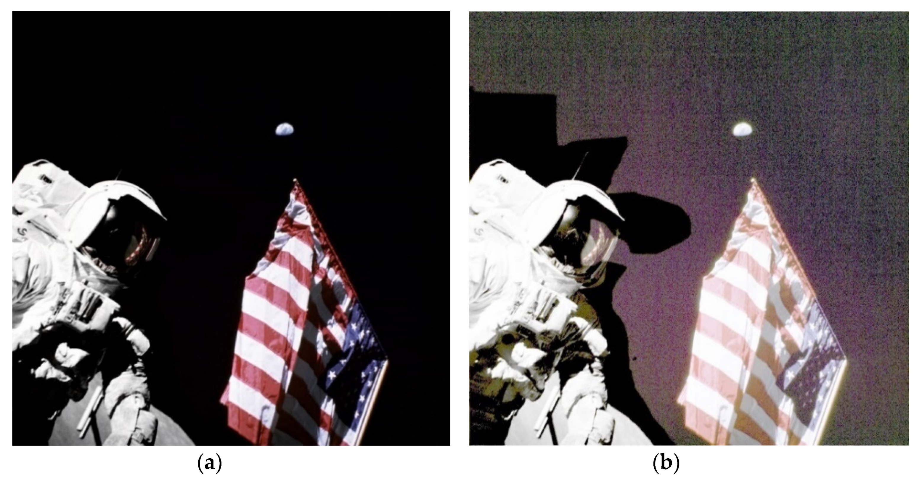
(a) According to NASA, the photo shows astronaut-geologist Harrison Schmitt, pilot of the Apollo 17 lunar module, who was photographed near the American flag while reaching the lunar surface. The picture was taken on 13 December 1972 in the Taurus Littrow region. The upper end of the flag points to our planet Earth in the background; (b) same photo with increased gamma correction.
Figure 1.
(a) According to NASA, the photo shows astronaut-geologist Harrison Schmitt, pilot of the Apollo 17 lunar module, who was photographed near the American flag while reaching the lunar surface. The picture was taken on 13 December 1972 in the Taurus Littrow region. The upper end of the flag points to our planet Earth in the background; (b) same photo with increased gamma correction.

Figure 2.
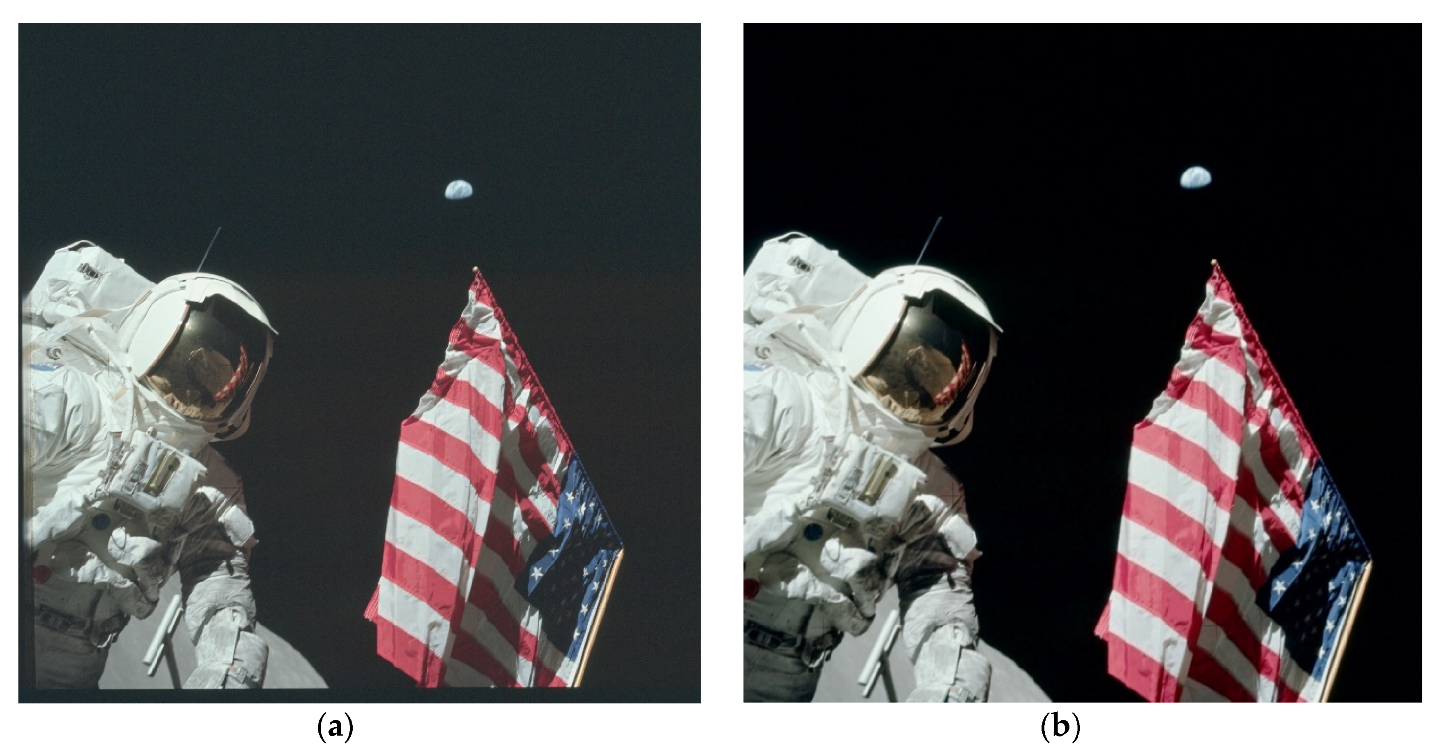
AS17-134-20384, found in: (a) the project Apollo archive of flickr.com [13]; (b) the Apollo 17 Image Library [16].

Figure 3.
Examination and comparison of the noise of a real photo with photo GPN-2000-00113 clearly shows that GPN-2000-00113 is composed of two parts separated by a black background with no noise on it. (a) Random uniform noise on an actual photo; (b) Wikipedia-commons photo (1998); (c) Internet Archive photo (1972).

Figure 4.
Stellarium software simulation of the view over Apollo 17 landing site showing the Earth at about SW and at an altitude angle of 45°32′57″.
Figure 4.
Stellarium software simulation of the view over Apollo 17 landing site showing the Earth at about SW and at an altitude angle of 45°32′57″.

Figure 5.
Detailed view of the Earth as shown from the landing site of Apollo 17. Australia and Antarctica could clearly be seen if the cloud formations permitted at the time.
Figure 5.
Detailed view of the Earth as shown from the landing site of Apollo 17. Australia and Antarctica could clearly be seen if the cloud formations permitted at the time.

Figure 6.
Comparison of the Earth and its continents as shown by Stellarium software simulation and photo AS17-134-20384 (the equivalent of photo GPN-2000-00113) found in the Apollo 17 Image Library. (a) Stellarium software simulation of the view over Apollo 17 landing site showing the Earth as it would be seen on 12 December 1972, at 03:58:54. (b) Earth as seen in the photo AS17-134-20384 and found in the Apollo 17 Image Library. The red lines indicate the shape of Earth and Australia transferred from Stellarium simulation.

Figure 7.
Australia’s position at the time of photo capture: (a) an enlargement of Figure 6b of photo AS17-134-20384, found in the Apollo 17 Image Library of the official NASA webpages; (b) relative enlargement of photo AS17-134-20384, found in the Apollo 17 photos in the NASA commons Flickr account [13].

Figure 8.
Project Apollo Archive photo (part) AS17-134-20426 [30], showing Apollo 17 astronaut with camera held in the chest fixture.
Figure 8.
Project Apollo Archive photo (part) AS17-134-20426 [30], showing Apollo 17 astronaut with camera held in the chest fixture.

Figure 9.
The image was taken at an angle of 20° to the horizontal.

Figure 10.
Composite of photos AS17-134-20386 and AS17-134-20387 showing the actual position of the Earth relative to the astronauts and the line at which the camera should be in order to capture the scene in photo AS17-134-20384 (top left). Notice that the shadows, with a few degrees of error, are running parallel to the flag’s horizontal length.

Figure 11.
Flag imaged in photos AS17-134-20386 and AS17-140-21391. Since the flag’s height is 1.09 m, then the pole is about 2.50 m tall.
Figure 11.
Flag imaged in photos AS17-134-20386 and AS17-140-21391. Since the flag’s height is 1.09 m, then the pole is about 2.50 m tall.

Figure 12.
Apollo Nasa Library AS17-134-20384HR image used for the estimation of the astronaut height.
Figure 12.
Apollo Nasa Library AS17-134-20384HR image used for the estimation of the astronaut height.

Figure 13.
The apparent height of the Earth in photo AS17-134-20384 indicates that the astronaut-photographer, 1 m away from the flag end, can picture the Earth in the correct position on the photo when he holds his camera at 1.7 m above the ground.
Figure 13.
The apparent height of the Earth in photo AS17-134-20384 indicates that the astronaut-photographer, 1 m away from the flag end, can picture the Earth in the correct position on the photo when he holds his camera at 1.7 m above the ground.

Figure 14.
Reconstruction of the pole and the flag at the exact dimensions stated for Apollo 17 mission (flag, 1.09 m × 1.83 m—estimated pole height 2.5 m). The plastic pipe at the flag end is extended by 0.2 m to match the apparent position of the Earth above the top end of the flag.
Figure 14.
Reconstruction of the pole and the flag at the exact dimensions stated for Apollo 17 mission (flag, 1.09 m × 1.83 m—estimated pole height 2.5 m). The plastic pipe at the flag end is extended by 0.2 m to match the apparent position of the Earth above the top end of the flag.

Figure 15.
Reproduction photos taken from different heights from ground level and distances from the flag end (indicated on labels in each figure); (a) camera 1.0 m high from ground level and at 1.7 m distance from the flag end; (b) camera 1.2 m high from ground level and at 1.5 m distance from the flag end; (c) camera 1.5m high from ground level and at 1.2 m distance from the flag end; this is the most probable position of the Apollo 17 astronaut-photographer in a standing position with the camera fixed to his chest; (d–g) camera at 1.2 m distance from the flag end with relative movement up, down, left, and right.

Figure 16.
Reflection of the helmet (zoomed from photo AS17-134-20384).

Figure 17.
Comparison of astronaut imaged in photo AS17-134-20381HR (modified in “perspective wrapping” of Photoshop to match the view of the helmet) shows that the astronaut is standing, in conjunction with the indication of his shadow.
Figure 17.
Comparison of astronaut imaged in photo AS17-134-20381HR (modified in “perspective wrapping” of Photoshop to match the view of the helmet) shows that the astronaut is standing, in conjunction with the indication of his shadow.

Figure 18.
Comparison of the shadow of the astronaut shown in the helmet reflection of photo AS17-134-20384 and the astronaut imaged in photo AS17-134-20386 indicates that the astronaut is taking the photo in a standing position. The corresponding blue lines indicate the various parts of the body.
Figure 18.
Comparison of the shadow of the astronaut shown in the helmet reflection of photo AS17-134-20384 and the astronaut imaged in photo AS17-134-20386 indicates that the astronaut is taking the photo in a standing position. The corresponding blue lines indicate the various parts of the body.

Figure 19.
Reflection on a convex mirror. The top parts of the body are shown as more elongated than the lower ones, giving the impression that the photographer is viewed from above.
Figure 19.
Reflection on a convex mirror. The top parts of the body are shown as more elongated than the lower ones, giving the impression that the photographer is viewed from above.

Figure 20.
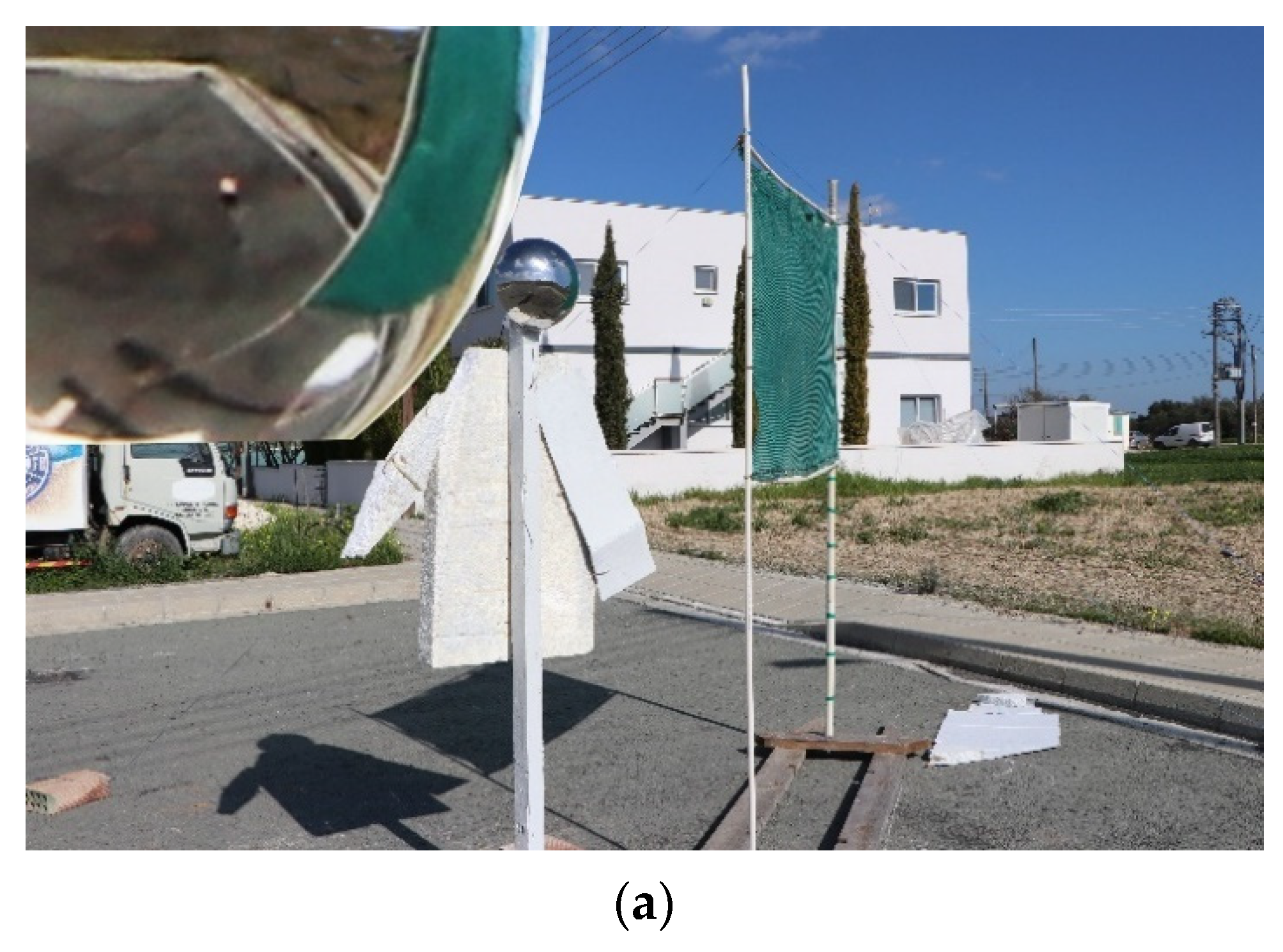
(a,b) Reproductions of photo AS17-134-20384 from different angles. The images taken at the correct position of the Sun (17° altitude), show the imaged astronaut, flag, and helmet and the photographer astronaut with its created shadow. Photos cleared from irrelevant objects.
Figure 20.
(a,b) Reproductions of photo AS17-134-20384 from different angles. The images taken at the correct position of the Sun (17° altitude), show the imaged astronaut, flag, and helmet and the photographer astronaut with its created shadow. Photos cleared from irrelevant objects.


Figure 21.
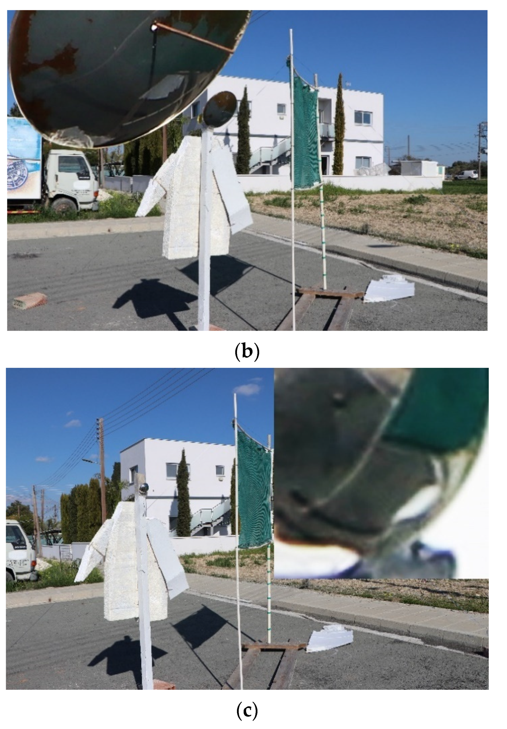
Reproduction: Photographer-astronaut standing at about 3.5 m distance from the flag end along a line running parallel to the length of the flag and about a distance of 0.5 m in (a) and 1.1 m in (b) between the parallel lines. In both cases, the shadow’s position on the ground is reflected on the helmet (see inset) and is seen to be touching the pole of the flag in its middle part below the flag. For a topographic presentation of the exact points, see also Figure 25, point A for Figure 21a and point B for Figure 21b.
Figure 21.
Reproduction: Photographer-astronaut standing at about 3.5 m distance from the flag end along a line running parallel to the length of the flag and about a distance of 0.5 m in (a) and 1.1 m in (b) between the parallel lines. In both cases, the shadow’s position on the ground is reflected on the helmet (see inset) and is seen to be touching the pole of the flag in its middle part below the flag. For a topographic presentation of the exact points, see also Figure 25, point A for Figure 21a and point B for Figure 21b.


Figure 22.
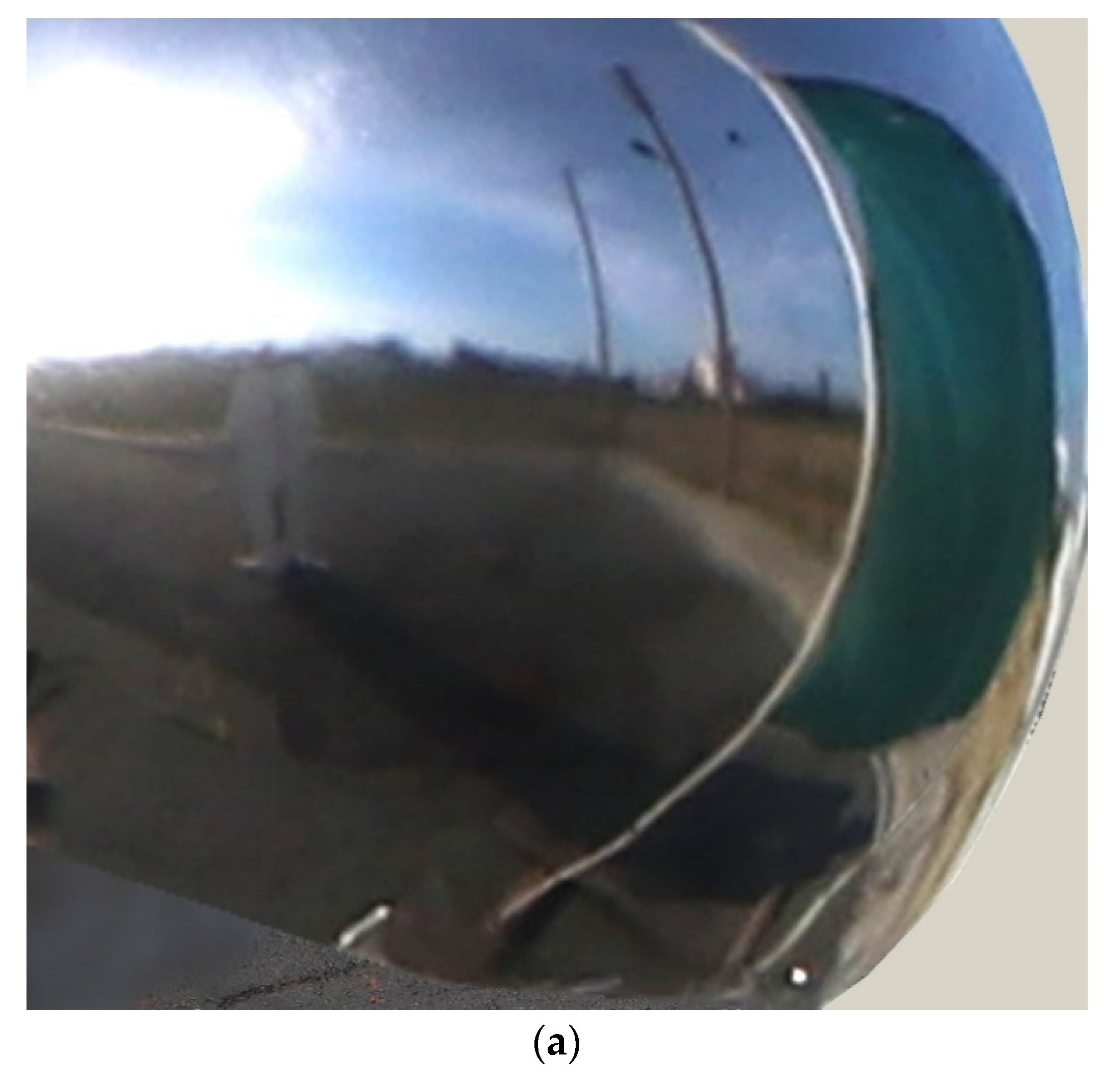
Comparison of the reflection reproduced on the mirror (a) to the one on the helmet (b). The point to which the shadow of the polystyrene board astronaut reaches to the flagpole indicates the distance of the astronaut taking the photo.
Figure 22.
Comparison of the reflection reproduced on the mirror (a) to the one on the helmet (b). The point to which the shadow of the polystyrene board astronaut reaches to the flagpole indicates the distance of the astronaut taking the photo.


Figure 23.
Reproduction: Photographer-astronaut standing near the line of capture indicated by the position of the Earth in the photo. The photographer’s shadow goes beyond the pole in the reflection of the helmet (see inset). Photographer is: (a) standing at a 1.8 m distance from the flag end along a line running parallel to the length of the flag and a distance of 0.5 m between the parallel lines; (b) standing at a 1.25 m distance from the flag end along a line running parallel to the length of the flag and a distance of 0.5 m between the parallel lines. For a topographic presentation of the exact points, see also Figure 25, point C for Figure 23a and point D for Figure 23b.


Figure 24.
Reflections with different diameters of mirrors: (a) spherical surface, 0.29 m diameter; (b) spherical surface, 0.64 m diameter; (c) spherical surface, 0.11 m diameter. For better clarity, the inset in each photo shows an enlargement of the cardboard ‘shadow’ and the base of the pole. Essentially, the relative position of objects is not affected, although an enlargement is produced by greater diameter mirrors and visa-versa.


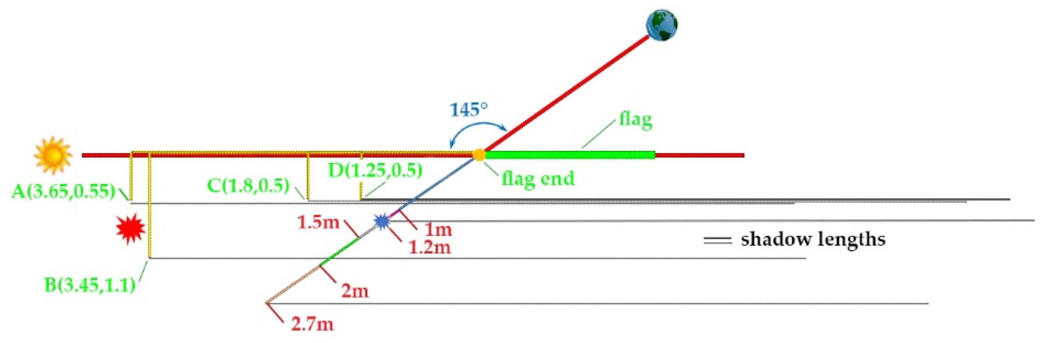
Figure 25.
Simulation results showing the astronaut’s position taking the photo estimated, first by the position of the Earth in the photo (1.2 m), blue mark; second by the position of the astronaut’s shadow on the screen reflection of the helmet (3.5 m from the flag end), red mark. A, B, C and D indicate the positions from which the images presented in Figure 21 and Figure 23 were captured. Numbers in parenthesis next to each letter indicate the horizontal distance in m from the flag end (left site of the flag) and the vertical distance (also in m) parallel to the flag.


Table 1.
Altitude and azimuth of Sun and Earth at the landing site of Apollo 17, at the time the photo was taken.
Table 1.
Altitude and azimuth of Sun and Earth at the landing site of Apollo 17, at the time the photo was taken.
| Astronomical Body | Altitude at 3:58:54 GMT | Azimuth at 3:58:54 GMT |
|---|---|---|
| Sun | +17°29′58.2″ | +96°39′44.7″ |
| Earth | +45°32′55.9″ | +241°41′52.4″ |
Table 2.
Estimation of various heights imaged in photos for flag size 1.09 m × 1.83 m unless otherwise noted.
Table 2.
Estimation of various heights imaged in photos for flag size 1.09 m × 1.83 m unless otherwise noted.
| Image No. | Flagpole (m) | Astronaut Height (m) | Distance of Camera from Flag (m) (Figure 13) | Astronaut Position Indicated by Shadow Length (m) (Figure 21) |
|---|---|---|---|---|
 AS17-134-20387 | 2.50 | 2.20 | 1.2 | 7 |
 AS17-134-20379 | 2.44/2.06 * | 2.12/1.79 * | - | - |
 AS17-134-20380 | 2.40/2.02 * | 2.14/1.81 * | 1.1 | 6.5 |
* if flag size 0.91 m × 1.53 m.
Publisher’s Note: MDPI stays neutral with regard to jurisdictional claims in published maps and institutional affiliations. |
© 2021 by the authors. Licensee MDPI, Basel, Switzerland. This article is an open access article distributed under the terms and conditions of the Creative Commons Attribution (CC BY) license (http://creativecommons.org/licenses/by/4.0/).
Share and Cite
MDPI and ACS Style
Amathes, P.; Christodoulides, P. Interpreting Locked Photographic Data: The Case of Apollo 17 Photo GPN-2000-00113. Designs 2021, 5, 8. https://0-doi-org.brum.beds.ac.uk/10.3390/designs5010008
AMA Style
Amathes P, Christodoulides P. Interpreting Locked Photographic Data: The Case of Apollo 17 Photo GPN-2000-00113. Designs. 2021; 5(1):8. https://0-doi-org.brum.beds.ac.uk/10.3390/designs5010008
Chicago/Turabian StyleAmathes, Pyrrhon, and Paul Christodoulides. 2021. "Interpreting Locked Photographic Data: The Case of Apollo 17 Photo GPN-2000-00113" Designs 5, no. 1: 8. https://0-doi-org.brum.beds.ac.uk/10.3390/designs5010008