
Ballast-Supported Foundation Designs for Low-Cost Open-Source Solar Photovoltaic Racking


1
Department of Civil & Environmental Engineering, Western University, London, ON N6A 5B9, Canada
2
Department of Mechanical & Materials Engineering, Western University, London, ON N6A 5B9, Canada
3
Department of Electrical & Computer Engineering, Western University, London, ON N6A 5B9, Canada
4
Ivey School of Business, Western University, London, ON N6G 0N1, Canada
*
Author to whom correspondence should be addressed.
Designs 2024, 8(1), 17; https://0-doi-org.brum.beds.ac.uk/10.3390/designs8010017
Submission received: 5 January 2024
/
Revised: 30 January 2024
/
Accepted: 1 February 2024
/
Published: 4 February 2024
Abstract
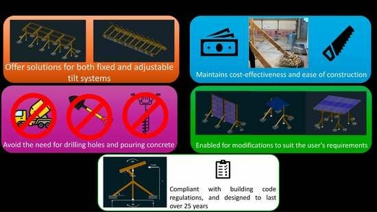
:Although solar photovoltaic (PV) system costs have declined, capital cost remains a barrier to widespread adoption. Do-it-yourself (DIY) system designs can significantly reduce labor costs, but if they are not attached to a building structure, they require ground penetrating footings. This is not technically and economically feasible at all sites. To overcome these challenges, this study details systems designed to (1) eliminate drilling holes and pouring concrete, (2) propose solutions for both fixed and variable tilt systems, (3) remain cost effective, and (4) allow for modifications to best fit the user’s needs. The ballast-supported foundations are analyzed for eight systems by proposing two separate ballast designs: one for a single line of post systems, and one for a double line of post systems, both built on a 4-kW basis. The results of the analysis found that both designs are slightly more expensive than typical in-ground concrete systems by 25% (assuming rocks are purchased at a landscaping company), but the overall DIY system’s costs remain economically advantageous. Sensitivity analyses are conducted to show how modifications to the dimensions influence the weight of the system and thus change the economic value of the design, so users can trade dimensional freedom for cost savings, and vice versa. Overall, all wood-based PV racking system designs provide users with cost-effective and easy DIY alternatives to conventional metal racking, and the novel ballast systems presented provide more versatility for PV systems installations.
1. Introduction
The primary impediment to a solar photovoltaic (PV)-powered society has been economics [1], but fortunately PV technology has enjoyed price declines for decades [2,3], so solar is now generally the lowest-cost electricity generation technology on both the small and large scales [4,5]. These new low costs and the fact that PV systems provide carbon-free electricity have enabled PVs to be the most rapidly-expanding electricity source [6,7]. At this point, PV systems are the dominant source of new power [8]. The PV industry continues to be primarily driven by large-scale centralized systems as these have been where energy policy is largely focused [9], but to achieve the U.N. ‘Sustainable Energy for All’ goals, it is clear that small-scale home-power PV systems can play a huge role [10,11]. These smaller systems can be both driven by the economic advantage for small prosumers to save money [12], but recent life cycle analysis also makes it clear that smaller systems are better for the environment [13]. Although even at the small-scale, PV systems are an economic benefit to the prosumer, the up-front investment for PV systems presents an economic barrier to consumers in the developing [14,15] and developed economies [16,17].
Most of the PV system cost reductions at any scale are due to PV module price drops, while price stagnation occurs in the balance of systems (BOS) costs (including racking, electronics, and wiring) [3,18,19]. For small-scale PV systems, racking costs are mainly driven by proprietary and costly aluminum extrusion profiles [20]. For example, PV module prices are around 0.125 USD/W [21], so the three modules for a 1 kW PV system cost USD 125 while a 3three-module rack costs USD 459 [22], which is three times the PV cost. More sophisticated racks cost even more as a three-PV module pole mount rack costs USD 1312 [23] (nine times the cost of the required PV modules).
The exorbitant costs of small-scale PV racks are an economic impediment for small-scale PV adoption as well as fast-growing areas of PV technology such as agrivoltaics [24,25] for small-scale farmers [26,27]. Agrivoltaics is the combination of agriculture and PVs on the same land to make solar electricity and grow food. Agrivoltaics proves to be efficient with a 35–73% increase in global land productivity [28], broadens the opportunities for PV systems [29], and can be combined with tracking systems to further increase productivity [30]. If the dual use of land and PVs was implemented worldwide, over 16,000 GWh of energy to meet the demands of over 15 million people can be generated [31]. Crops such as corn have been shown to yield great results [32], and it remains a viable option for most people as 80–90% of the land can be cultivated with standard practice and common machinery [33]. The solar PV racking structures used for agrivoltaics generally increase the cost of racking as they are higher off the ground, so they use more material [32,34], which again impedes the economics for small-scale PV prosumers. There is thus a critical need to reduce the capital costs of such racking systems.
One approach to reducing costs of small-scale PV systems is to use do-it-yourself (DIY) development of open source technologies [35]. This approach is well developed and there are open source hardware designs for the distributed production of PV racking of the following types of systems: (1) low-tilt angle PV racks for mobile arrays [36], (2) steel cable-based cross X-wire PV racking systems for flat commercial rooftops [37] and ground-mounted near the equator [38], (3) tensegrity-based solar PV racking [39], (4) after-market adaptions of conventional modules to allow for building-integrated PV (BIPV) [40], (5) fixed-tilt ground-mounted wood-based racks [41], (6) variable-tilt wood-based PV racks [42,43], (7) vertically mounted (sign-based) wood PV racks [44], (8) fence-based PVs for agrivoltaics on existing farm fencing [45], (9) aftermarket adaptation to make floatovoltaics (FPV) [46], (10) trellis-based agrivoltaics wood-based PV racks [47], (11) cable and pipe-based mobile photovoltaic racking [48], (12) cable based variable tilt racks [49], and (13) earth and shotcrete-based racking [50]. There are also many community-developed racking systems made from wood. Examples include simple two-by-four systems for quick and simple construction [51], a sturdier two-by-six system to stand up to Southern U.S. wind loads [52], a carport system to allow clearance for tractors [53], and a four-span system that can be made for as low as USD 130 [54]. Wood and metal hybrid systems provide longer spans and larger column spacing [55,56,57,58]. Metal temporary [59] and metal permanent [60,61] designs are also proposed on a DIY small scale. All of these systems can be constructed using common hand and power tools by individuals with minimal construction experience and ability, but none of them have been evaluated by peer-review nor have they had professional engineering evaluations. There are several DIY kits available [62,63,64,65]. All of these PV racks not attached to buildings, however, involve ground penetration. Holes must be 1.2 m into the ground to penetrate below the frost line and avoid heaving [66]. Typically, ground penetrating systems require renting an augur, which can cost over USD 100 a day [67], or require intensively shoveling, which may easily cost more than USD 100 in labor costs based on the size of the system. In both cases, even if labor costs are ignored the requirements of ground penetration provide barriers to adoption (e.g., renting the equipment can be expensive or shoveling can be too physically demanding in some soil types). In addition, concrete may take a day to solidify, and up to 28 days to reach its specified strength [68]. There is a need for open-source design adaptations that eliminate these barriers. No racking design, however, is available in the literature with the flexibility to be mounted in locations where ground penetrations are not technically feasible or too costly.
To fill this need, this study details a system designed to eliminate both drilling holes and pouring concrete into the ground for PV systems. Conventional concrete footings may be difficult or even impossible in northern regions as well as being suboptimal for agrivoltaics where farmers generally do not want the soil disturbed. Two different designs are investigated in this study to assess their structural integrity, constructability, and cost when fabricated with a ballast-supported foundation. Three trellis systems, adopted from Jamil et al. [47], minimize the number of required posts and thus provide sufficient clearance for agrivoltaic purposes [69]. A variable tilt system adopted from Vandewetering et al. [42] and Jamil et al. [49] allows the user to convert physical labor into useful energy by changing the tilt angle based on the season. Overall, all these wooden PV racking systems provide users with cost-effective and easy DIY alternatives to conventional metal racking, and ballast systems would allow for much more versatility in the way these PV systems can be installed. This study specifically analyzes the ballast-supported foundations for such wood-based systems by proposing two separate ballast designs: one for a single line of post systems, and one for a double line of post systems. Each type of ballast system is built on a 4-kW basis. The cost of each total system, along with the foundation costs are presented and compared to traditional ground penetrating concrete systems. Sensitivity analyses are conducted to show how modifications to the dimensions and weight of the system change the economic value of the design.
2. Materials and Methods
2.1. Renewable Materials Selection for Racking: Wood
Wood was selected as the primary building material based on its low cost, high availability, and ease of construction. Additionally, wood as a construction material for PV racking provides environmental advantages. Unlike other conventional materials, responsibly sourced wood is sustainable [70], renewable, and comprised of approximately half carbon, which was recently taken from the atmosphere. Wood has a negative combined embodied energy and embodied carbon over alternative racking construction materials. Aluminum, which is the most common PV racking material, has over 5 times the embodied CO2 e/kg of wood, even with 31% recycled content [71]. Wood construction may thus also be eligible for carbon credits [72,73].
2.2. Material Properties
Construction grade pressure-treated lumber and hardware purchased from typical hardware stores is used for this design. Different grades and species of lumber can be used based on the cost and availability in any specific region. The National Design Specification for Wood Construction [74] provides structural capacities for lumber of all dimensions and species. In London, ON, Canada, grade No. 2 spruce-pine-fir (SPF) lumber is the most commonly sold grade at typical hardware stores and is used for the design of these systems.
2.3. PV Racking Basic Design Parameters
Systems that can be built with a ballast foundation are broken down into two different categories: (1) systems with a single line of posts within an array, and (2) systems with two lines of posts within an array. The two ballast foundation designs are assessed by analyzing two different types of wood racking systems: the sloped T-shaped system, and the variable tilt system. Although all these systems serve different purposes, the foundations of all the single line of post systems have very similar foundation designs. The same is also the case for the double line of post systems. A breakdown of each system’s categorization is shown in Table 1.

Table 1.
Categorization of single line of post systems and double line of post systems.
| System Type | System | Reference |
|---|---|---|
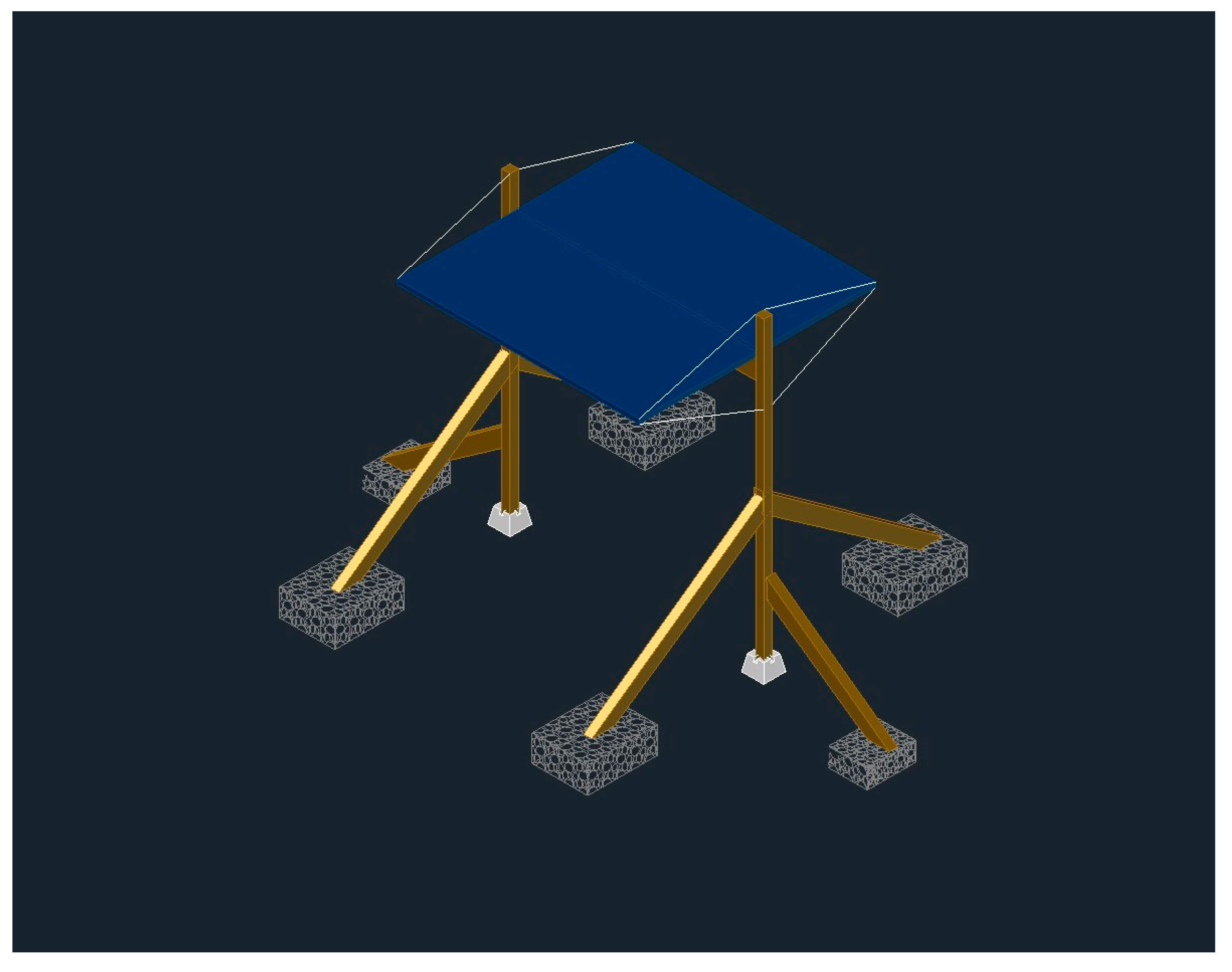
| Single Line of Posts | Sloped T-Shaped System | Figure 1 [47] |
| Inverse Y System | Figure 2 [47] | |
| T-Shaped System | Figure 3 [47] | |
| Swinging Vertical System | Figure 4 [44] | |
| Wire Rope System 1 | Figure 5 [49] | |
| Single-Spot Carport System 2 | Figure 6 [75] | |
| Double Line of Posts | Variable Tilt System 1 | Figure 7 [42] |
| Fixed Tilt System | Figure 8 [41] |
1 Variable tilt angle system. 2 Although this system has two lines of posts, it requires the single line of posts ballast foundation to allow vehicles to enter and exit under it.
The wooden ballast racking is designed to be widely applicable and accessible for users with many different needs. These systems can be designed for any desired clearance to allow for agricultural growth and equipment mobilization. As expected, the tradeoff to this is that more clearance corresponds to a greater cost, so users can design a system to match their dimensional and economical constraints. Additionally, the systems can be built to any desired tilt angle to maximize the energy yield based on the geography. In this study as an example, 34° is the optimal tilt angle for London, ON, Canada [41], and is used for the design of these systems.
2.4. Design Analysis Assumptions
These systems are compliant with the National Building Code of Canada [66] for design loads of a structure to last at least 25 years, which conveniently matches the warranty and expected lifetime of many PV modules. The material properties of the wood used follow the values derived from the National Design Specification for Wood Construction [74].
Since the superstructure of these systems is inspired by the Vandewetering et al. [42] and Jamil et al. [47] designs, these ballast systems undertake the same design processes, and thus every component except for the footings will be designed the same way. Ballast systems take on the challenge of not being supported by fixed concrete footings. Instead, the system is supported by concrete deck blocks resting on the ground, which provide adequate bearing, but are subject to rotation and even tip-over. Therefore, the weight of each gabion required to support the system from tipping-over is critical and thus is calculated. A gabion is taken from the Italian gabbione meaning “big cage”, which is a cage or basket filled with rocks and is common in many types of landscaping and civil engineering projects.
2.5. Economic Analysis
The economic costs of these systems are obtained from local hardware stores and a local landscape supply company in London, ON, Canada. Vandewetering et al. address the cost and feasibility of obtaining these products throughout different parts of the world, suggesting that these products can be purchased almost everywhere, but users in the United Kingdom, for example, may pay up to double the price in lumber [42]. Nevertheless, this economic analysis methodology remains useful worldwide.
For the system to last the design life of 25 years, the foundations are required to withstand a worst-case wind force prescribed by the National Building Code of Canada. The Appendix A, Appendix B and Appendix C outlines how to calculate the weight of rocks required on both ends to resist the uplift induced by the wind force. SiteOne Supply is the supplier used for the building of these systems, which provides a cost per cubic yard for 2″ river stone. The cost is converted into a cost per lb, using the density (lbs/cubic yard) provided on the website, and is then multiplied by the total number of lbs required for each basket. The total cost of rocks is presented by multiplying the cost per basket by the number of baskets required to hold a 4-kW system.
A comparison between the single line of post systems and double line of post systems will be conducted by comparing the cost between the sloped T-shaped system and the variable tilt system. The bills of materials for the systems are also presented. Each system cost is based on a 4-kW system, where the total cost and the cost per W is provided. The total cost of the newly proposed ballast foundations is isolated and presented as well. In this study, the cost of ballast foundations is presented in three ways: (1) the total foundation cost, (2) the foundation cost as a percentage of the superstructure, and (3) the foundation cost as a percentage of the cost of a concrete foundation.
The number of rocks required, and thus the foundation cost, are highly variable based on the type of system, the location of the build, the desired vertical clearance, and the distance between the rock baskets. To account for this variability, a sensitivity analysis is provided to measure the effect of each of these variables on the final foundation cost. This includes a sensitivity for found rocks (e.g., some locations have abundant and free rocks available that can be used).
Furthermore, the final costs of these systems are subject to change based on the cost of lumber at the time of purchase and where the material is being purchased [76]. A sensitivity analysis is provided on both commodity wood pricing and location to provide a range of final costs and costs per W of each system.
3. Results
3.1. Foundation Weight Requirements
The Appendices outlines how to calculate the weight of rocks required on both ends to resist the uplift induced by the wind force. For the sloped T-shaped system, the required weight per typical inside basket is 590 lbs. For the variable tilt system, the weight is 1930 lbs per basket, or 193 lbs per m per side. SiteOne Supply charges CAD 70 per cubic yard, and states that 2–4″ river stone has a typical density of 2900 lbs per cubic yard [77]. This equates to a rate of CAD 0.024 per lb. The breakdown for the cost of rocks in Canadian Dollars (CAD) for these systems is provided in Table 2 and Table 3.
3.2. T-Shaped Fixed Tilt Rack
3.2.1. Bill of Materials (BOM) for Fixed-Tilt Rack
3.2.2. Sloped T-Shaped Fixed Tilt Assembly Instructions
The system requires at least 2 builders to install. The superstructure can be built in the same manner as outlined in Jamil et al. [47]. The posts can then be placed into the deck blocks. Space 2 posts far enough to fit in a frame, and temporarily brace the posts with diagonal members, such as unused 2 × 4 planks. This will ensure that the posts are stable while installing the frame, and to ensure the temporary construction does not blow over while being built.
Rock baskets can now be formed and installed onto the posts. A piece of ½″ pressure-treated plywood is cut to the desired basket dimensions. In this case, 600 mm × 600 mm pieces were used. Then, chicken wire is wrapped around the plywood to allow it to form into the shape of a basket with an opening on the top as shown in Figure 9. The basket must have a height at which rocks will not tumble out. Excess wire roll is cut with either tin snips or a metal grinder. Any openings in the chicken wire should be closed in by either tying the two ends of the wire together, or by connecting them with a loose metal tie.
A 2 × 6 diagonal is now set to the post and to the plywood. The 2 × 6 s are cut to the desired angle, such as 45 degrees, and a diagonal is connected to the middle of the plywood using two fence brackets as shown in Figure 10. This connection is duplicated for the post. If the chicken wire of the basket is in the way of the diagonal connecting to the post, an opening is cut in the basket to allow the 2 × 6 to pass through.
The contained rectangular basket of chicken wire is filled with a weight of rocks equal to the required design weight as calculated in the Appendices. The rocks should be 2″ or greater in size so they cannot fall through the gaps of the chicken wire. A completed ballast foundation is shown in Figure 11. This process is repeated for each required basket.
3.3. Variable Tilt Rack
3.3.1. Bill of Materials for Variable Tilt Rack
The BOM of a 4 kW variable tilt rack is shown in Table 5 in Canadian dollars sourced from Copp’s Build-All, London, ON, Canada, and SiteOne Supply, London, ON, Canada.
3.3.2. Variable Tilt Ballast System Assembly Instructions
Similar to the sloped T-shaped system, the variable tilt system requires at least 2 builders to install, and the superstructure can be built in the same manner as outlined in Vandewetering et al. [42]. For this design, the gabion baskets are installed throughout the length of the system with one continuous basket. Long strips of plywood can be used and can be butted together if they are connected with continuous chicken wire. Rocks should be equally spread throughout. If there is not a great enough length of chicken wire to make one continuous basket the whole way through, a second roll can be tied and secured to the first roll. The chicken wire is formed in the same manner as shown in Figure 9. The diagonals, which are now much shorter, are connected in the same way as detailed in Figure 10, but can be used with any scrap piece of lumber.
3.4. Economic Analysis
To compare the cost of ballast foundations to traditional foundations, the cost of concrete for each system scaled to 4 kW is provided in Table 6.
A comparison of a system built on concrete foundations compared to a system built as a ballast foundation is provided in Table 7.
Found materials could also be used to reduce the costs (e.g., in some areas rocks are abundant and free on site). In the case that the rocks can be acquired for free, a system comparison between free rocks and purchased rocks is shown in Table 8. As can be seen in Table 8, this drops the costs 8–14%. It should be noted that the ballast rock is simply providing weight, so specific types of rocks are not necessary. Found materials may not be available in all areas and some areas may not even have rock of any type available. In such locations other suitable ballasts may be found such as construction or demolition debris. Future work is needed to look at other solutions such as sand and waste plastic composites that could be adequate long-lifetime ballasts in such regions. In general, however, found ballast will be the most economic and rock is a relatively low-cost ballast material in most of the world.
Each of these system’s superstructure will reduce in cost per W if they are built larger in scale. This is because of the ratio of outside posts to inside posts. Outside posts carry the load for one half section, while inside posts carry the load for two half sections, which means that a system consisting of more inside posts is economically more efficient. The cost benefit of scaling, however, does not apply to the ballast foundations. This is because these are proposed as a per linear m or per basket basis. Therefore, doubling the size of the system effectively doubles the cost of the foundation with little to no savings.
The wind load, calculated using the process outlined in the National Building Code of Canada [66], is based on many parameters, one of them being the location of the system. Assuming all other factors are fixed, the 1-in-50-year wind pressure, q, linearly impacts the wind force on the modules, which linearly changes the weight of rocks required. A summary of the corresponding q values for locations throughout Canada and the resulting cost of rocks required for each type of system is provided in Table 8, Table 9 and Table 10. It is observed that there is minimal difference in foundation cost when installing a system in different interior cities, but major increases occur when this system is built on a windy rural coast. In the extreme case, such as Cape Race, Newfoundland, where the wind load is more than double that of typical urban cities, this system becomes challenging. The applicability of these systems worldwide [76], much like in Canada, is dependent on the calculated wind load, and the individual’s decision in deeming if the build is feasible based on the cost of rocks associated with this wind speed.
As shown in the Appendices, the distance to the center of the modules, d, has a direct correlation to increasing the price. A summary of varying clearances and their respective cost is provided in Table 11 and Table 12. In the single line of posts systems, the effect is linear, as in doubling the clearance requires double the weight of rocks. The impact is, however, magnified in the double line of posts system, as doubling the clearance actually results in the weight being multiplied by a factor of 2.62.
The last factor that has an impact on the total weight of rocks required is the distance between the baskets of foundations. As shown in the Appendices calculations, the baskets serve as a couple moment counteracting the wind force, and thus, the farther apart they are, the less force is required to counteract. The effect of increasing or decreasing these distances is shown in Table 13 and Table 14. Single line post systems have a linear relationship, as doubling the distance cuts the weight of each basket in half, while the double line of post has varying results when the distance is modified.
It should also be noted that hardware stores and suppliers may provide additional cost savings by purchasing in bulk. Furthermore, delivery charges for orders are typically a flat charge regardless of the order size, therefore it is in one’s best interest to scale these systems as large as possible to minimize the delivery costs.
4. Discussion
4.1. Limitations
4.1.1. Preservatives
Although no wood is in contact with the ground in any of these systems, it is advised to purchase pressure-treated lumber rated for ground contact. The higher the rating, the more preservative chemicals are in the wood, which provides a greater life expectancy but will typically cost more. In North America, typically one grade of ground contact pressure-treated lumber, and one grade of in-ground rated posts are exclusively sold. If a non-treated system was used, the system cost is roughly 60% of the cost of a treated system but will not have nearly the same life expectancy and is therefore not recommended. A treated wood solar rack can last a lifetime common to the PV warranties of 25 years if installed in accordance with the manufacturer’s instructions [79]. Since the posts are supported on concrete deck blocks, the system is not in direct contact with the ground, making it comparable to typical in-ground concrete foundation systems. Particular care, however, should be taken if the build is in a high wood deterioration zone. The Forestry Chronicle provides a decay hazard map that presents high hazards of decay in British Colombia, for example [80]. Treated wood must be disposed of properly once it comes to the end of its service life, which currently usually means taking it to a landfill or transfer station as it should not be burned. Future work should be conducted to create an environmentally benign method of recycling this wood such as low temperature pyrolysis [81].
4.1.2. Wood Species Alternatives
If using pressure-treated lumber is not preferred, there are species that offer natural decay resistance. White cedar and western red cedar are commonly sold as alternatives in the North for roughly 2.5 times the cost of pressure-treated lumber. Cedar has a slightly higher structural capacity compared to SPF pressure-treated lumber [74], and may have a longer life expectancy.
4.1.3. Soil Conditions
The problems that arise with installing the system exclusively on the ground are the problems that come with the properties of the topsoil, and the possibility of weak underlying soil. Topsoil is typically a weak material subject to local settlements. Additionally, since wooden racking systems are much lighter than the metal counterparts, the system can be subject to frost heave and result in local uplifts at certain footings. If the land that these systems are installed on consists of soft soils and organic topsoil, it is advised to bear the deck blocks on a pad of gravel to provide drainage and minimize settlement and frost heave [82]. A conservative estimate on the bearing capacity can be made by selecting the appropriate soil classification and its respective bearing capacity using Table 9, from 4.4.1 of the National Building Code of Canada [66]. For a small-scale system, it is not economically practical to conduct a soil analysis, so if the soil classification is unknown, the bearing capacity can safely be taken as 75 kPa. Even for softer clays, the size of the rock basket foundations are more than large enough to ensure there is no bearing failure under the proposed loads; however, in extreme cases where highly organic marshes are being loaded, larger-area rock baskets can be formed to reduce the bearing pressure on sensitive soils, or additional pads of gravel can be installed under the rock baskets.
4.1.4. Uneven Land
If larger systems are built that span long distances, it can be expected that the ground level on one end of the system may not match the other. If the change in grade is dramatic, this can result in an unserviceable system. This issue may be resolved in two different ways; the land can either be cut and filled to provide an even grade, or the much less labor intensive and more cost-effective alternative is to rest the deck blocks on lower ground and install longer posts to offset the difference. It should be noted that longer lengths, typically limited to 16′, are more costly, and require reanalyzing the post’s structural capacity. Therefore, it is advised to plan to install these systems on the most even grade of land possible or to break the systems into smaller sections to minimize these issues.
4.1.5. Construction Staging
Since this system is built above the ground, there is a significant lack of stability in the system up until the rock foundations are installed. This may result in premature mid-construction failures, even from mild breezes of wind. To prevent this failure from occurring, extra lumber, such as scrap 2 × 4 planks, should be used as temporary lateral bracing until construction is complete. Although using 2 × 4 planks for temporary use can be seen as an additional cost, this significantly outweighs the additional cost associated with replacing a failed structure, receiving fines from authorities, and from injuring a builder. Temporary diagonal members attached between each post prevent the system from tipping over and can globally stabilize the system to also make installation much easier.
4.1.6. Safety
In many locations including Canada, safety is a major concern for DIY systems. Those that build these systems or others should follow reasonable safety precautions as they would for any other DIY project but should not have undue fear for several reasons. First, as was already pointed out, there are no necessary construction standards for this type of PV racking as the safety risks associated with this type of fabrication would be similar to that of making a picnic table (a common final project for boy scouts). The calculations to ensure mechanical and load-related safety are presented in this manuscript. In terms of fire and electric safety, the electrical connections to a PV system (assuming it is grid-integrated) still undergo the same inspections that a conventional system installer would need to undergo. So, for example, in the U.S. the electrical system would normally be inspected by the electric utility and the municipality. In Ontario, Canada, a third completely redundant inspection takes place to obtain the Electrical Safety Authority’s (ESA) approval as well. This extra inspection only increases the cost of PV systems in Ontario with no demonstrated benefits as there is no evidence in the literature that redundant safety inspections result in more safety (e.g., reduces mortality or injuries) nor is there any evidence that ESA-approved electrical devices are safer in any way than jurisdictions using other safety standards in the rest of Canada, the U.S., Europe, or Asia. Future work should quantify how the ESA system is both a drag on innovation in Ontario, but also a barrier to renewable energy deployment for marginalized communities and the poor as the fraction of a PV system cost due to ESA inspection costs and equipment costs increases as the size of the PV system decreases. Lastly, it should be stressed that the tie into the grid needs to be performed by a licensed electrician in most jurisdictions. So again, the parts of a PV system installation where there is any substantial risk of harm/electrocution would be completed by a professional.
4.2. Wood Price Sensitivity
Open-source wood-based PV racks provide substantial savings in Canada, but the benefit in building a system in other countries depends on the lumber availability in each region [76]. Previous work investigating the economics of racking in the Americas has shown that wood-based PV racking was economically advantageous in all of North America (Canada, U.S., and Mexico) as well as countries such as Argentina, however, in other South American countries, metal racking was advantageous [76]. Thus, it is very clear that this approach is highly dependent on the price differential of building materials in different countries. As this system is mostly wood-based, the system is highly sensitive to the price of lumber, which recently has been volatile because of the COVID-19 pandemic. Supply shortages from 2020–2022 resulted in major price fluctuations shown in Figure 12. The market has caught up since then, however, and is beginning to reach equilibrium once again now that prices are approaching the prior 20-year average.
This system is designed to meet Canadian standards, which are higher for construction than most of the world due to the combination of snow loads and high wind loads. In Canada, although roof-mounted PV systems require professional engineering stamps and building permits to install, these ground-mounted systems do not require these. This makes this approach accessible to unskilled labor. Racking only requires a professional engineer’s stamped approval if the racking is not CSA approved [84]. In the case of this system, all wood used is marked and graded as SPF No.2 grade, which indicates CSA’s approval for structural use. The design complies with the National Research Council’s National Building Code of Canada, which works together with CSA, and the National Design Specification for Wood Construction, which follows CSA O86:19 Engineering design in wood.
Most municipalities, such as the City of Toronto, do not require building permits for ground-mounted PV systems of any size, and thus plans and calculations do not need to be stamped and signed by a registered engineer [85]. Some municipalities, such as the City of Waterloo, specify that building permits are not required such that the system is not connected to water or heating resources [86]. Very few municipalities, such as the city of London, only require a work permit if excavation is required, or if scaffolding and cranes are used [87]. In all cases, these ground-mounted PV systems are an exceptional alternative to roof-mounted systems because they avoid a lot of the red tape and costs associated with tying to an existing structure. This allows costs to remain low, construction to be completed quickly, and PV systems to remain a feasible option as a DIY alternative. It should be stressed here that for regions where the wood cost is lower than the metal cost, even if PV system owners are not personally adept enough for DIY building, cost savings carry through for this design if the same labor costs are used for metal- and wood-based racking.
For agrivoltaic applications, the use of pressure-treated lumber can pose the threat of introducing toxic chemicals into the vegetation. Historically, pressure-treated lumber contained chromated copper arsenate to protect the wood from rotting, which caused major health and environmental concerns, but has been discontinued and replaced with copper azole preservative since 2004 [88]. Copper azole is a much safer alternative because it removes exposure to chromium and arsenic, and copper is already abundant in soil and groundwater; however, high doses of copper can result in severe liver and kidney damage [89].
Therefore, if this system is in close contact with vegetation, it is highly advised to prevent pressure-treated lumber from contacting the soil. The designs here can be made to avoid contact with the soil. In addition, natural alternatives such as cedar lumber can be used, but the cost is approximately 2.5 times that of pressure-treated wood. The best solution to eliminate soil contact completely is to place an additional layer of rocks under the rock baskets to ensure that no pressure-treated plywood is in close contact with the soil.
5. Future Work
In some regions, wind loads can be substantial and thus the weight of rocks required to support the system may be too large and labor-intensive. Therefore, a rotating alternative can be built that is designed to fail after a certain wind speed and begin spinning the modules. Shear blocks, pins, or other component couplings may be installed on the system to support the frame and fix it at a desired tilt angle. Then, once a 1-in-100-year wind speed occurs, the shear blocks break, and the frame may begin to spin. This will allow the foundations to be designed for a much lower wind speed, and thus a much lower weight of rocks, while still being able to stand up to virtually any wind speed. In addition, other sources of ballast can be investigated including designs that can use soil or sand, as well as waste materials such as mine tailings, stamp sand [90], or waste-plastic sand composites [91,92].
Most ballast systems are used for roof-mounted racks [93,94,95,96,97]. Although these systems would be built in the same manner as ground-mounted systems, these designs require building permits and structural engineering stamps as they now impose an additional load on a building. Innovations have been made to help minimize the wind load and thus the weight of ballasts [98,99], but installing solar power on rooftops can increase the wind load on the roof by a factor of two based on the tilt angle and location [100]. Currently, there is no simplified method of assessing the feasibility of installing ballast systems on standardized structural systems for rooftops, and structural approval is completed on a building-by-building basis, and can cost anywhere from CAD 900 [101] to CAD 5000 or more per rooftop. Future work should be conducted to eliminate the need for case-by-case engineering approval of PV ballast systems so that newly built rooftops can automatically be built with PVs, and existing standardized rooftops can implement PVs such that they surpass a specific structural condition. This necessary future work perhaps underscores a trend in global society towards professionalization of every aspect of human life. In the distant past, all humanity was capable of fabricating their personal needs (e.g., shelter, clothing, tools, foods, etc.) and then the industrial revolution tipped the economic advantage to specialization and mass manufacturing. Today, most of the developed world is completely dependent on this specialization/mass manufacturing system for all of their needs. The advent, however, of mass sharing of information enabled by the Internet and the rise of open-source technological development (first in software and now fully entrenched in hardware) has enabled a new path that makes the DIY of a vast array of products accessible to moderately technically sophisticated people [102]. The development of digital manufacturing technologies (e.g., 3D printers, laser cutters, CNC mills, etc.) and their reduced costs have enabled a massive resurgence of DIY in the modern maker movement [103,104]. The results here indicate an economic advantage and increased flexibility even for products such as PV racking manufactured by hand, but future work is needed to determine if such designs would be scaled laterally by large numbers of users. Substantial future work is also needed to determine if these trends in manufacturing, fabrication, and construction are reversing themselves to make a DIY producer society [105] or if the DIY/maker culture has only limited reach to the technically sophisticated. This work will necessitate investigating these trends globally to determine if the availability of high-quality DIY designs such as those provided in this study provides a means of presumption to lift local populations out of poverty [106] and is a rich area of future research.
6. Conclusions
Ballast systems prove to be a viable racking alternative, especially when drilling holes into the ground is not possible or economically prohibitive. Rock basket weights can easily be calculated to build a system to last 25 years that is compliant with building code standards and is scalable to systems of any size. Two designs were proposed to accommodate systems with a single line of posts, and systems with two lines of posts. For 4 kW systems, the single and double line of posts systems were priced at just over 0.34 CAD/W and 0.32 CAD/W, respectively, and remove the labor costs involved with renting an auger and shoveling post holes. Where rocks can be acquired for free, users can see system savings of 14.3% for the single line of post systems, and 7.9% for the double line of post systems. The location, dimensions, clearance, and rock basket distance of the system have a large influence on the weight of rocks required due to the wind speed each location experiences. Ballast systems are shown to remain economical in almost all locations in Canada with the exception of the windy coasts. It should be pointed out that wood-based ballast foundation systems cost 24–26% more than wood-based in-ground concrete foundations. Thus, if the location allows for ground penetration, concrete footing is economically advantageous using a DIY wood-based structure. If it is not, in North America and other regions where the differential price of wood compared to metal is favorable, the DIY wood-based ballast system provides the lowest capital costs. Future investigation is to be conducted to assess the potential of ballast systems with rotating frames to substantially reduce the basket weights, system cost, and thus provide more opportunities for DIY photovoltaic builds.
7. OSHWA Certification in Place of Patents
Upon acceptance, the designs will be OSHWA certified, and the number will be added here.
Author Contributions
Conceptualization, J.M.P.; methodology, N.V. and U.J.; software, N.V.; validation, N.V. and U.J.; formal analysis, J.M.P., N.V. and U.J.; investigation, N.V.; resources, J.M.P.; data curation, N.V.; writing—original draft preparation J.M.P., N.V. and U.J.; writing—review and editing, J.M.P., N.V. and U.J.; visualization, N.V. and U.J.; supervision, J.M.P.; funding acquisition, J.M.P. All authors have read and agreed to the published version of the manuscript.
Funding
This research was funded by the Thompson Endowment.
Data Availability Statement
Data will be made available upon request.
Conflicts of Interest
The authors declare no conflicts of interest. The funders had no role in the design of the study; in the collection, analyses, or interpretation of data; in the writing of the manuscript; or in the decision to publish the results.
Nomenclature
| BIPV | Building Integrated Photovoltaics |
| BOM | Bill of materials |
| BOS | Balance of Systems |
| CSA | Canadian Standards Association |
| DIY | Do-it-yourself |
| FPV | Floatovoltaics |
| NBCC | National Building Code of Canada |
| OSHWA | Open Source Hardware Association |
| PV | Photovoltaic |
| SPF | Spruce-pine-fir |
| U.N. | United Nations |
| CAD | Canadian dollars |
| b | Member breadth |
| C | Compression force |
| d | Distance between baskets |
| E | Modulus of elasticity |
| F | Force |
| h | Height to the center of modules |
| I | Moment of inertia |
| M | Moment |
| q | Wind pressure |
| V | Wind speed |
| W | Self-weight |
| Tilt angle | |
| Coefficient of static friction | |
| ρ | Air density |
| Diagonal angle |
Appendix A. Foundation Design Load Calculations
Since the designs of these systems are similar to those from Vandewetering et al. [42] and Jamil et al. [47], the structural analysis and wood selection process can be replicated. The foundation designs of the ballast designs are unique, and the weight of rocks required can vary based on the system tilt angle, the height above the ground, and the location wind speed.
Calculating the wind load applied to the structure follows the same procedure as described in Vandewetering et. al. If the wind pressure, q, is not readily tabulated, it can be calculated using the wind pressure Equation (A1) shown below,
where ρ is the density of air, and V is the 1-in-50-year wind speed. NBCC suggests taking a ρ value of 1.29 kg/m3 [56].
Once a wind load is calculated, it can be broken into individual point loads to assess the required weight for each rock basket. The point load, F, for either an interior or exterior basket is calculated using Equations (A2) and (A3) below. It should be noted that point loads on the inside of the system will have double the tributary area of the point loads of the outside, so outside point loads will be half the value, meaning that the rock baskets on the outside must only be half the weight of those on the inside.
For the two line of post systems, the rock baskets are continuous and are not separated, but the weight is still assessed on a per module area basis.
F is applied perpendicular to the face of the modules. This point load can be broken into two components, one component providing a lateral force, and another providing a downwards/uplift force. These components are calculated using Equations (A4) and (A5).
where is the tilt angle of the modules. The system must now be checked to ensure it does not fail from sliding and overturning.
Appendix B. Single Line of Post Foundation Design Weight Calculations
Appendix B.1. Sliding
Although it should not typically govern the design of the rock baskets, the system must be checked to ensure that the lateral load does not push the system forward. The lateral load, Fcos(, must be resisted by the frictional force as shown in Figure A1, which is calculated using Equation (A6) below.
Figure A1.
Sloped T-shaped sliding free body diagram.

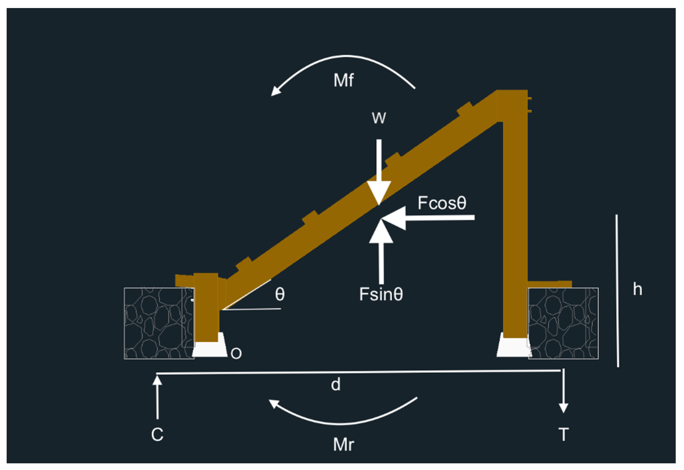
Appendix B.2. Overturning
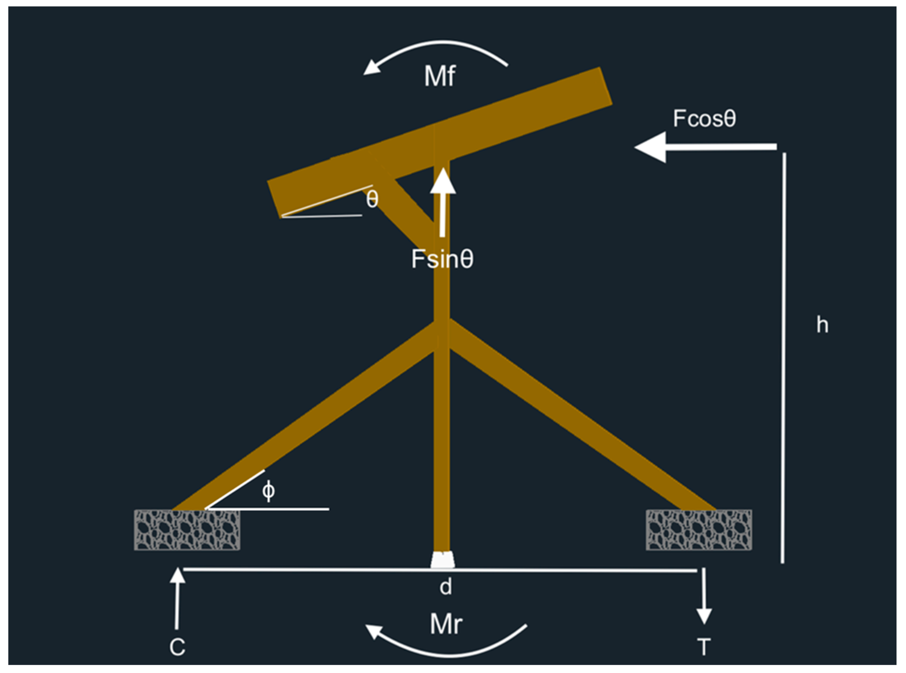
The overturning of the system about the post footing will typically govern the required weight of the rock baskets. The compressive load of the rocks is assumed to be sufficient to carry any load from the rack. Overturning is assessed by providing the system with a resisting moment, Mr, to the factored moment induced by the wind load, Mf. The free body diagram of the system is provided in Figure A2.
Figure A2.
Sloped T-shaped overturning free body diagram.

Since the system will have a smooth transfer from the rocks to the wooden diagonals, the tensile resistance force is equal to the weight of the rocks in a basket. The wind load can be converted into an equivalent applied bending moment, Mf, calculated using Equation (A7).
This moment is counteracted by the resisting moment created from the rocks, Mr, thus Mr and Mf are equal. On one side, the rocks will provide a compressive force, C, and on the other side, the rocks will provide a tensile force, T. These forces must be equal and opposite, and therefore they are couple forces to create a couple moment. These forces are calculated using Equation (A8).
It is assumed that the rocks have enough capacity to carry the compressive force, as the system will always fail via overturning before the rocks will ever crush under the applied load. Therefore, the compressive resistance of the rocks can be neglected. The tensile force, T, is what is required for design, and is simply equal to the weight of the rocks.
Although the uplift force, Fsin(), does not contribute to the overturning moment because it acts upon the centroid of the system, it increases the tensile force required to keep the system down. Each rock basket will hold down half of the uplift force. The net amount of weight per basket required is finally calculated using Equation (A9).
For the sloped T-shaped system in London, ON, Canada, typical interior rock baskets require a weight of at least 590 lbs, and outside baskets require 295 lbs of rocks.
Appendix B.2.1. Diagonal Design
The diagonals connected from the post to the basket should be checked to ensure that they do not experience a tensile failure or a compressive failure. The tensile/compressive force that these members experience are calculated using Equation (A10).
where is the angle of the diagonal as shown in Figure A2. The tensile capacity for wooden members is outlined in Jamil et al. [47], and it should be ensured that a member with capacity greater than the force demand is selected.
Since these members are rather slender and have a far unsupported length, the buckling capacity is checked using the Euler buckling Equation (A11) with the moment of inertia upon the weak axis, Iweak, found in Equation (A12).
Appendix B.2.2. Global-Lateral Foundation Design
The system must also be designed to resist the lateral wind loads as shown in the free body diagram in Figure A3. The same sliding and overturning checks must be used for this case, however the weight of rocks required will be must smaller as there is now a much smaller wind area acting on a much deeper section.
Figure A3.
Sloped T-shaped global-lateral free-body diagram.

This design process is replicable for any of the single line of post designs.
For vertical rotating systems, the modules are free to swing as the wind attacks them. Therefore, the stress induced on the system only results from wind attacking the wood structure and inertia forces from swinging modules. The loads acting on the system are assessed in Vandewetering et al., and the weight of rocks is calculated in a similar manner. Solving for T, the weight of rocks required for a system in London, ON, Canada, is 590 lbs per typical inside basket.
Appendix C. Double Line of Posts Foundation Design Calculations
For the double line of posts systems, the sliding check is the same as the single line of post check. The overturning design is slightly different from the single line of post process because the uplift force now contributes an additional moment because it is no longer concentrated at the tipping point, and the self-weight of the system counteracts overturning. The free-body diagram of this system is shown in Figure A4, where O represents the tipping point at the post base.
Figure A4.
Variable tilt system free-body diagram.

The moment from the own weight, Mow, is equal to the weight of the system times the distance from the tipping point to the center of the system. The uplift moment is calculated using the same distance since this force acts at the same location. The uplift moment is added to Mf and the own weight moment subtracts from it. The design of this system now uses the same equations and process as outlined in the single line of post design.
The weight of rocks is solved in the same manner as the single line of post systems, but now as a per module basis. The total amount of weight required per side is calculated by multiplying the weight per module by the number of modules.
References
- Karakaya, E.; Sriwannawit, P. Barriers to the Adoption of Photovoltaic Systems: The State of the Art. Renew. Sustain. Energy Rev. 2015, 49, 60–66. [Google Scholar] [CrossRef]
- Fu, R.; Feldman, D.J.; Margolis, R.M. US Solar Photovoltaic System Cost Benchmark: Q1 2018; OSTI: Oak Ridge, TN, USA, 2018. [Google Scholar]
- Matasci, S. Solar Panel Cost: Avg. Solar Panel Prices by State in 2019: EnergySage; EnergySage: Boston, MA, USA, 2019. [Google Scholar]
- Dudley, D. Renewable Energy Will Be Consistently Cheaper than Fossil Fuels by 2020. Forbes, 13 January 2018. Available online: https://www.forbes.com/sites/dominicdudley/2018/01/13/renewable-energy-cost-effective-fossil-fuels-2020/?sh=c991ff44ff2e(accessed on 14 December 2023).
- Solar Industry Research Data|SEIA. Available online: https://www.seia.org/solar-industry-research-data (accessed on 2 January 2024).
- Renewable Electricity Growth Is Accelerating Faster than Ever Worldwide, Supporting the Emergence of the New Global Energy Economy—News. Available online: https://www.iea.org/news/renewable-electricity-growth-is-accelerating-faster-than-ever-worldwide-supporting-the-emergence-of-the-new-global-energy-economy (accessed on 2 February 2024).
- Vaughan, A. Time to Shine: Solar Power Is Fastest-Growing Source of New Energy. The Guardian, 4 October 2017. Available online: https://www.theguardian.com/environment/2017/oct/04/solar-power-renewables-international-energy-agency(accessed on 14 December 2023).
- Barbose, G.L.; Darghouth, N.R.; LaCommare, K.H.; Millstein, D.; Rand, J. Tracking the Sun: Installed Price Trends for Distributed Photovoltaic Systems in the United States; 2018 Edition; Lawrence Berkeley National Laboratory: Berkeley, CA, USA, 2018. [Google Scholar]
- IEA. Solar PV—Renewables—Analysis. 2020. Available online: https://www.iea.org/reports/renewables-2020/solar-pv (accessed on 18 October 2023).
- Levin, T.; Thomas, V.M. Can Developing Countries Leapfrog the Centralized Electrification Paradigm? Energy Sustain. Dev. 2016, 31, 97–107. [Google Scholar] [CrossRef]
- Chakrabarty, S.; Islam, T. Financial Viability and Eco-Efficiency of the Solar Home Systems (SHS) in Bangladesh. Energy 2011, 36, 4821–4827. [Google Scholar] [CrossRef]
- Lang, T.; Ammann, D.; Girod, B. Profitability in Absence of Subsidies: A Techno-Economic Analysis of Rooftop Photovoltaic Self-Consumption in Residential and Commercial Buildings. Renew. Energy 2016, 87, 77–87. [Google Scholar] [CrossRef]
- Roy, R.; Pearce, J.M. Is Small or Big Solar Better for the Environment? Comparative Life Cycle Assessment of Solar Photovoltaic Rooftop vs. Ground-Mounted Systems. Int. J. Life Cycle Assess. 2023, 1–21. [Google Scholar] [CrossRef]
- Agenbroad, J.; Carlin, K.; Ernst, K.; Doig, S. Minigrids in the Money: Six Ways to Reduce Minigrid Costs by 60% for Rural Electrification; Rocky Mountain Institute: Basalt, CO, USA, 2018. [Google Scholar]
- Szabó, S.; Pinedo Pascua, I.; Puig, D.; Moner-Girona, M.; Negre, M.; Huld, T.; Mulugetta, Y.; Kougias, I.; Szabó, L.; Kammen, D. Mapping of Affordability Levels for Photovoltaic-Based Electricity Generation in the Solar Belt of Sub-Saharan Africa, East Asia and South Asia. Sci. Rep. 2021, 11, 3226. [Google Scholar] [CrossRef] [PubMed]
- Awan, A.B. Optimization and Techno-Economic Assessment of Rooftop Photovoltaic System. J. Renew. Sustain. Energy 2019, 11, 033501. [Google Scholar] [CrossRef]
- Wang, P.; Yu, P.; Huang, L.; Zhang, Y. An Integrated Technical, Economic, and Environmental Framework for Evaluating the Rooftop Photovoltaic Potential of Old Residential Buildings. J. Environ. Manag. 2022, 317, 115296. [Google Scholar] [CrossRef] [PubMed]
- Fthenakis, V.; Alsema, E. Photovoltaics Energy Payback Times, Greenhouse Gas Emissions and External Costs: 2004–Early 2005 Status. Prog. Photovolt. Res. Appl. 2006, 14, 275–280. [Google Scholar] [CrossRef]
- Feldman, D.; Barbose, G.; Margolis, R.; Bolinger, M.; Chung, D.; Fu, R.; Seel, J.; Davidson, C.; Darghouth, N.; Wiser, R. Photovoltaic System Pricing Trends: Historical, Recent, and Near-Term Projections; 2015 Edition; US Department of Energy: Washington, DC, USA, 2015. [Google Scholar]
- Feldman, D.; Barbose, G.; Margolis, R.; Wiser, R.; Darghout, N.; Goodrich, A. Photovoltaic (PV) Pricing Trends: Historical, Recent, and Near-Term Projections; Sunshot Vision Study; US Department of Energy: Washington, DC, USA, 2012. [Google Scholar]
- PVInsights. PVInsights. Available online: http://pvinsights.com/ (accessed on 23 August 2023).
- Tamarack Solar Products. Tamarack Solar Top of Pole Mounts. Available online: https://www.altestore.com/store/solar-panel-mounts/top-of-pole-mounts-for-solar-panels/tamarack-solar-top-of-pole-mounts-6072-cell-solar-panels-p40745/ (accessed on 29 June 2023).
- TPM3. Pole Mount for Three 60/72 Cell Solar Modules—Modern Outpost. Available online: https://www.modernoutpost.com/product/tpm3-pole-mount-for-three-60-72-cell-solar-modules/ (accessed on 2 January 2024).
- Precedence Research. Agrivoltaics Market Is Expected to Increase at a 12.15% of CAGR by 2030. Available online: https://www.precedenceresearch.com/press-release/agrivoltaics-market (accessed on 23 August 2023).
- International Energy Agency. Solar. Available online: https://www.iea.org/energy-system/renewables/solar-pv (accessed on 23 August 2023).
- Mahto, R.; Sharma, D.; John, R.; Putcha, C. Agrivoltaics: A Climate-Smart Agriculture Approach for Indian Farmers. Land 2021, 10, 1277. [Google Scholar] [CrossRef]
- Feuerbacher, A.; Herrmann, T.; Neuenfeldt, S.; Laub, M.; Gocht, A. Estimating the Economics and Adoption Potential of Agrivoltaics in Germany Using a Farm-Level Bottom-up Approach. Renew. Sustain. Energy Rev. 2022, 168, 112784. [Google Scholar] [CrossRef]
- Dupraz, C.; Marrou, H.; Talbot, G.; Dufour, L.; Nogier, A.; Ferard, Y. Combining Solar Photovoltaic Panels and Food Crops for Optimising Land Use: Towards New Agrivoltaic Schemes. Renew Energy 2011, 36, 2725–2732. [Google Scholar] [CrossRef]
- Guerin, T.F. Impacts and Opportunities from Large-Scale Solar Photovoltaic (PV) Electricity Generation on Agricultural Production. Environ. Qual. Manag. 2019, 28, 7–14. [Google Scholar] [CrossRef]
- Valle, B.; Simonneau, T.; Sourd, F.; Pechier, P.; Hamard, P.; Frisson, T.; Ryckewaert, M.; Christophe, A. Increasing the Total Productivity of a Land by Combining Mobile Photovoltaic Panels and Food Crops. Appl. Energy 2017, 206, 1495–1507. [Google Scholar] [CrossRef]
- Mavani, D.D.; Chauhan, P.M.; Joshi, V. Beauty of Agrivoltaic System Regarding Double Utilization of Same Piece of Land for Generation of Electricity & Food Production. Int. J. Sci. Eng. Res. 2019, 10, 118–148. [Google Scholar]
- Sekiyama, T.; Nagashima, A. Solar Sharing for Both Food and Clean Energy Production: Performance of Agrivoltaic Systems for Corn, A Typical Shade-Intolerant Crop. Environments 2019, 6, 65. [Google Scholar] [CrossRef]
- Agostini, A.; Colauzzi, M.; Amaducci, S. Innovative Agrivoltaic Systems to Produce Sustainable Energy: An Economic and Environmental Assessment. Appl. Energy 2021, 281, 116102. [Google Scholar] [CrossRef]
- Daniels, T.L. The Development of Utility-Scale Solar Projects on US Agricultural Land: Opportunities and Obstacles. Socio-Ecol. Pract. Res. 2023, 5, 205–213. [Google Scholar] [CrossRef]
- Grafman, L. To Catch the Sun: Inspiring Stories of Communities Coming Together to Harness Their Own Solar Energy, and How You Can Do It Too! Humboldt State University Press: Arcata, CA, USA, 2021; ISBN 978-1-947112-62-9. [Google Scholar]
- Wittbrodt, B.; Laureto, J.; Tymrak, B.; Pearce, J.M. Distributed Manufacturing with 3-D Printing: A Case Study of Recreational Vehicle Solar Photovoltaic Mounting Systems. J. Frugal Innov. 2015, 1, 1. [Google Scholar] [CrossRef]
- Wittbrodt, B.T.; Pearce, J.M. Total U.S. Cost Evaluation of Low-Weight Tension-Based Photovoltaic Flat-Roof Mounted Racking. Sol. Energy 2015, 117, 89–98. [Google Scholar] [CrossRef]
- Wittbrodt, B.; Pearce, J.M. 3-D Printing Solar Photovoltaic Racking in Developing World. Energy Sustain. Dev. 2017, 36, 1–5. [Google Scholar] [CrossRef]
- Arefeen, S.; Dallas, T. Low-Cost Racking for Solar Photovoltaic Systems with Renewable Tensegrity Structures. Sol. Energy 2021, 224, 798–807. [Google Scholar] [CrossRef]
- Pearce, J.M.; Meldrum, J.; Osborne, N. Design of Post-Consumer Modification of Standard Solar Modules to Form Large-Area Building-Integrated Photovoltaic Roof Slates. Designs 2017, 1, 9. [Google Scholar] [CrossRef]
- Vandewetering, N.; Hayibo, K.S.; Pearce, J.M. Impacts of Location on Designs and Economics of DIY Low-Cost Fixed-Tilt Open Source Wood Solar Photovoltaic Racking. Designs 2022, 6, 41. [Google Scholar] [CrossRef]
- Vandewetering, N.; Hayibo, K.S.; Pearce, J.M. Open-Source Design and Economics of Manual Variable-Tilt Angle DIY Wood-Based Solar Photovoltaic Racking System. Designs 2022, 6, 54. [Google Scholar] [CrossRef]
- Nlinventor. Ground Mounted Solar Panels with Adjustable Angles. Available online: https://www.instructables.com/Ground-Mounted-Solar-Panels-With-Adjustable-Angles/ (accessed on 2 January 2024).
- Vandewetering, N.; Hayibo, K.S.; Pearce, J.M. Open-Source Vertical Swinging Wood-Based Solar Photovoltaic Racking Systems. Designs 2023, 7, 34. [Google Scholar] [CrossRef]
- Masna, S.; Morse, S.M.; Hayibo, K.S.; Pearce, J.M. The Potential for Fencing to Be Used as Low-Cost Solar Photovoltaic Racking. Sol. Energy 2023, 253, 30–46. [Google Scholar] [CrossRef]
- Mayville, P.; Patil, N.V.; Pearce, J.M. Distributed Manufacturing of after Market Flexible Floating Photovoltaic Modules. Sustain. Energy Technol. Assess. 2020, 42, 100830. [Google Scholar] [CrossRef]
- Jamil, U.; Vandewetering, N.; Pearce, J.M. Solar Photovoltaic Wood Racking Mechanical Design for Trellis-Based Agrivoltaics. PLoS ONE 2023, 18, e0294682. [Google Scholar] [CrossRef]
- Franz, J.; Morse, S.; Pearce, J.M. Low-Cost Pole and Wire Photovoltaic Racking. Energy Sustain. Dev. 2022, 68, 501–511. [Google Scholar] [CrossRef]
- Wood and Cable-Based Variable Tilt Stilt-Mounted Solar Photovoltaic Racking System[v1]|Preprints.Org. Available online: https://www.preprints.org/manuscript/202312.0086/v1 (accessed on 27 December 2023).
- Hollman, M.R.; Pearce, J.M. Geographic Potential of Shotcrete Photovoltaic Racking: Direct and Low-Concentration Cases. Sol. Energy 2021, 216, 386–395. [Google Scholar] [CrossRef]
- DIY Ground Mounted Solar Array. Available online: https://www.mobile-solarpower.com/ground-mount-solar-array.html (accessed on 2 January 2024).
- UnpluggedTexan. How to Build a DIY Ground Mount Solar Panel Rack. Available online: https://www.youtube.com/watch?v=BKYSW4zRyVg (accessed on 2 January 2024).
- DIY Solar Panel Ground Mounting. Available online: https://signaturesolar.com/solar-news/diy-solar-panel-ground-mounting/ (accessed on 2 January 2024).
- Country View Acres Building. Our First Solar Array. Easy, Low Cost Solar Ground Mount. Available online: https://www.youtube.com/watch?v=EZEq7Hdoz_E (accessed on 2 January 2024).
- Johnson, M. Off Grid Living. How to Build the Ultimate DIY Solar Panel Ground Mount. Available online: https://www.youtube.com/watch?v=7t4hGBWLtxM (accessed on 2 January 2024).
- BuilditSolar. DIY PV System—Building the Mounts. Available online: https://www.builditsolar.com/Projects/PV/EnphasePV/Mounts.htm (accessed on 2 January 2024).
- Everyday Solar Best DIY Solar Ground Mount|Complete Assembly. Available online: https://www.youtube.com/watch?v=IgeaQs1OUtE (accessed on 2 January 2024).
- Country Living Experience: A Homesteading Journey Finally an Affordable Solar Panel Ground Mount! Installation DIY EG4. Available online: https://www.youtube.com/watch?v=RX6kdvptl6s (accessed on 2 January 2024).
- Solano, E. How to Build a DIY Solar Panel Ground Mount—Tinktube. Available online: https://tinktube.com/free-plans/diy-solar-panel-ground-mount/ (accessed on 2 January 2024).
- Poz, D. Building A DIY Solar Array Ground Mount (Part 1). Available online: https://www.youtube.com/watch?app=desktop&v=tc-wgpGfbtA (accessed on 2 January 2024).
- Iduna’s Orchard DIY Solar Ground Mount (Simple, Cheap!). Available online: https://www.youtube.com/watch?v=6R8_HE2xt8g (accessed on 2 January 2024).
- Sirois, É. 10 DIY Solar Panel Rack Ideas—Tinktube. Available online: https://tinktube.com/diy-ideas/diy-solar-panel-rack-ideas/ (accessed on 2 January 2024).
- 30 Solar Panel Ground Mounting Kit IronRidge. Available online: https://sunwatts.com/30-solar-panel-ground-mounting-kit-ironridge/ (accessed on 5 January 2024).
- Solar Panels Ground Mount. DIY KIT—4.62kW. Prairie Sun Sol. Available online: https://prairiesunsolar.com/product/ground-mount-diy-kit-4/ (accessed on 5 January 2024).
- Ground Mount Solar Panel Kits for Sale|GoGreenSolar. Available online: https://www.gogreensolar.com/collections/ground-mount-solar-panel-kits (accessed on 5 January 2024).
- National Research Council Canada. National Building Code of Canada. 2015. Available online: https://nrc.canada.ca/en/certifications-evaluations-standards/codes-canada/codes-canada-publications/national-building-code-canada-2015 (accessed on 17 February 2022).
- 2 Man Auger Rental|The Home Depot Canada. Available online: https://www.homedepot.ca/en/home/tool-and-vehicle-rental/p.2-man-auger.08822.html (accessed on 27 December 2023).
- Concrete Compressive Strength Variation with Time. Available online: https://theconstructor.org/concrete/concrete-compressive-strength-variation-with-time/5933/ (accessed on 27 December 2023).
- Mamun, M.A.A.; Dargusch, P.; Wadley, D.; Zulkarnain, N.A.; Aziz, A.A. A Review of Research on Agrivoltaic Systems. Renew. Sustain. Energy Rev. 2022, 161, 112351. [Google Scholar] [CrossRef]
- Lehmann, S. Sustainable Construction for Urban Infill Development Using Engineered Massive Wood Panel Systems. Sustainability 2012, 4, 2707–2742. [Google Scholar] [CrossRef]
- Embodied Carbon Footprint Database. Available online: https://circularecology.com/embodied-carbon-footprint-database.html (accessed on 2 January 2024).
- Hildebrandt, J.; Hagemann, N.; Thrän, D. The Contribution of Wood-Based Construction Materials for Leveraging a Low Carbon Building Sector in Europe. Sustain. Cities Soc. 2017, 34, 405–418. [Google Scholar] [CrossRef]
- Salazar, J.; Meil, J. Prospects for Carbon-Neutral Housing: The Influence of Greater Wood Use on the Carbon Footprint of a Single-Family Residence. J. Clean. Prod. 2009, 17, 1563–1571. [Google Scholar] [CrossRef]
- 2018 NDS. Available online: https://awc.org/publications/2018-nds/ (accessed on 8 March 2022).
- Vandewetering, N.; Hayibo, K.S.; Pearce, J.M. Open-Source Photovoltaic—Electrical Vehicle Carport Designs. Technologies 2022, 10, 114. [Google Scholar] [CrossRef]
- Rana, S.; Vandewetering, N.; Powell, J.; Ariza, J.Á.; Pearce, J.M. Geographical Dependence of Open Hardware Optimization: Case Study of Solar Photovoltaic Racking. Technologies 2023, 11, 62. [Google Scholar] [CrossRef]
- SiteOne Stone Centre—Delivering Landscape Supplies in London, Ontario. Available online: https://www.east.siteone.ca/ (accessed on 14 December 2023).
- Copp’s Buildall. London’s Local Hardware & Building Supply Specialists. Available online: https://www.coppsbuildall.com/?store=4 (accessed on 14 December 2023).
- Adpearance, I. What You Need to Know About Pressure Treated Wood|AIFP|PDX, OR. Available online: https://www.lumber.com/blog/what-you-need-to-know-about-pressure-treated-wood (accessed on 17 February 2022).
- Setliff, E.C. Wood Decay Hazard in Canada Based on Scheffer’s Climate Index Formula. For. Chron. 1986, 62, 456–459. [Google Scholar] [CrossRef]
- Helsen, L.; Bulck, E.; Hery, J.-S. Total Recycling of CCA Treated Wood Waste by Low-Temperature Pyrolysis. Waste Manag. 1998, 18, 571–578. [Google Scholar] [CrossRef]
- Frost Heave Prevention or How to Stop Frost Heaving. Available online: https://www.ecohome.net/guides/3628/what-causes-frost-heave-read-here-how-to-prevent-and-fix-frost-heaving/ (accessed on 27 December 2023).
- Lumber 2022 Data—1978–2021 Historical—2023 Forecast-Price-Quote-Chart. Available online: https://tradingeconomics.com/commodity/lumber (accessed on 26 July 2022).
- Municipal Climate Change Action Centre in Alberta. Available online: https://mccac.ca/ (accessed on 2 January 2024).
- City of Toronto. Solar Permitting & Regulations. Available online: https://www.toronto.ca/services-payments/water-environment/net-zero-homes-buildings/solar-to/solar/ (accessed on 27 November 2023).
- Solar Panels. Available online: https://www.waterloo.ca/en/living/solar-panels.aspx (accessed on 27 November 2023).
- Building Permits|City of London. Available online: https://london.ca/living-london/building-renovating/building-permits (accessed on 29 November 2023).
- US EPA. Overview of Wood Preservative Chemicals. Available online: https://www.epa.gov/ingredients-used-pesticide-products/overview-wood-preservative-chemicals (accessed on 28 May 2022).
- Haywood, S. The Effect of Excess Dietary Copper on the Liver and Kidney of the Male Rat. J. Comp. Pathol. 1980, 90, 217–232. [Google Scholar] [CrossRef]
- Rasmussen, T.; Fraser, R.; Lemberg, D.S.; Regis, R. Mapping Stamp Sand Dynamics: Gay, Michigan. J. Great Lakes Res. 2002, 28, 276–284. [Google Scholar] [CrossRef]
- Kumi-Larbi, A., Jr.; Galpin, R.; Manjula, S.; Lenkiewicz, Z.; Cheeseman, C. Reuse of Waste Plastics in Developing Countries: Properties of Waste Plastic-Sand Composites. Waste Biomass Valorization 2022, 13, 3821–3834. [Google Scholar] [CrossRef]
- Seghiri, M.; Boutoutaou, D.; Kriker, A.; Hachani, M.I. The Possibility of Making a Composite Material from Waste Plastic. Energy Procedia 2017, 119, 163–169. [Google Scholar] [CrossRef]
- Kern, E.C. Ballast-Mounted PV Arrays: Phase 2 Final Report; Ascension Technology, Inc.: Lincoln, MA, USA, 2000. [Google Scholar]
- Fanney, A.H.; Weise, E.R.; Henderson, K.R. Measured Impact of a Rooftop Photovoltaic System. J. Sol. Energy Eng. 2003, 125, 245–250. [Google Scholar] [CrossRef]
- Flat Roof Solar Racking. Available online: https://www.polarracking.com/rooftop-solar-mounting-system/flat-roof-solar-racking/ (accessed on 2 February 2024).
- Wills, R.; Milke, J.A.; Royle, S.; Steranka, K. Best Practices for Commercial Roof-Mounted Photovoltaic System Installation; Springer: Berlin/Heidelberg, Germany, 2015; ISBN 978-1-4939-2883-5. [Google Scholar]
- Franklin, D.E. Mounting Your Solar Photovoltaic (PV) System; SARE: College Park, MD, USA, 2016. [Google Scholar]
- Peek, R.T. Innovative Ballasted Flat Roof Solar PV Racking System; Cascade Engineering: Grand Rapids, MI, USA, 2014. [Google Scholar]
- Roecker, C. New Mounting Systems for PV on Buildings. In Renewable Energies for the New Millenium; Springer: Berlin/Heidelberg, Germany, 2000. [Google Scholar]
- Alrawashdeh, H.; Stathopoulos, T. Wind Loads on Solar Panels Mounted on Flat Roofs: Effect of Geometric Scale. J. Wind Eng. Ind. Aerodyn. 2020, 206, 104339. [Google Scholar] [CrossRef]
- P.Eng Stamped Structural Roof Assessment—Structural Roof Load Assessment|Solar Roof Installation Permitting Service. Available online: https://solarpowerstore.ca/products/p-eng-stamped-structural-roof-assessment (accessed on 4 January 2024).
- Pearce, J.M. Create, Share, and Save Money Using Open-Source Projects; McGraw-Hill Education: New York, NY, USA, 2020; ISBN 978-1-260-46176-3. [Google Scholar]
- Dougherty, D. The Maker Movement. Innov. Technol. Gov. Glob. 2012, 7, 11–14. [Google Scholar] [CrossRef]
- Camburn, B.; Wood, K. Principles of Maker and DIY Fabrication: Enabling Design Prototypes at Low Cost. Design Studies 2018, 58, 63–88. [Google Scholar] [CrossRef]
- Stangler, D.; Maxwell, K. DIY Producer Society. Innov. Technol. Gov. Glob. 2012, 7, 3–10. [Google Scholar] [CrossRef]
- Fox, S. Third Wave Do-It-Yourself (DIY): Potential for Prosumption, Innovation, and Entrepreneurship by Local Populations in Regions without Industrial Manufacturing Infrastructure. Technol. Soc. 2014, 39, 18–30. [Google Scholar] [CrossRef]
- Friction Coefficients—Slab on Grade. Available online: https://structx.com/Material_Properties_007.html (accessed on 27 December 2023).
Figure 1.
Sloped T-shaped ballast system.

Figure 2.
Inverse Y ballast system.

Figure 3.
T-shaped ballast system.

Figure 4.
Swinging vertical ballast system.

Figure 5.
Wire rope ballast system.

Figure 6.
Single spot carport system.

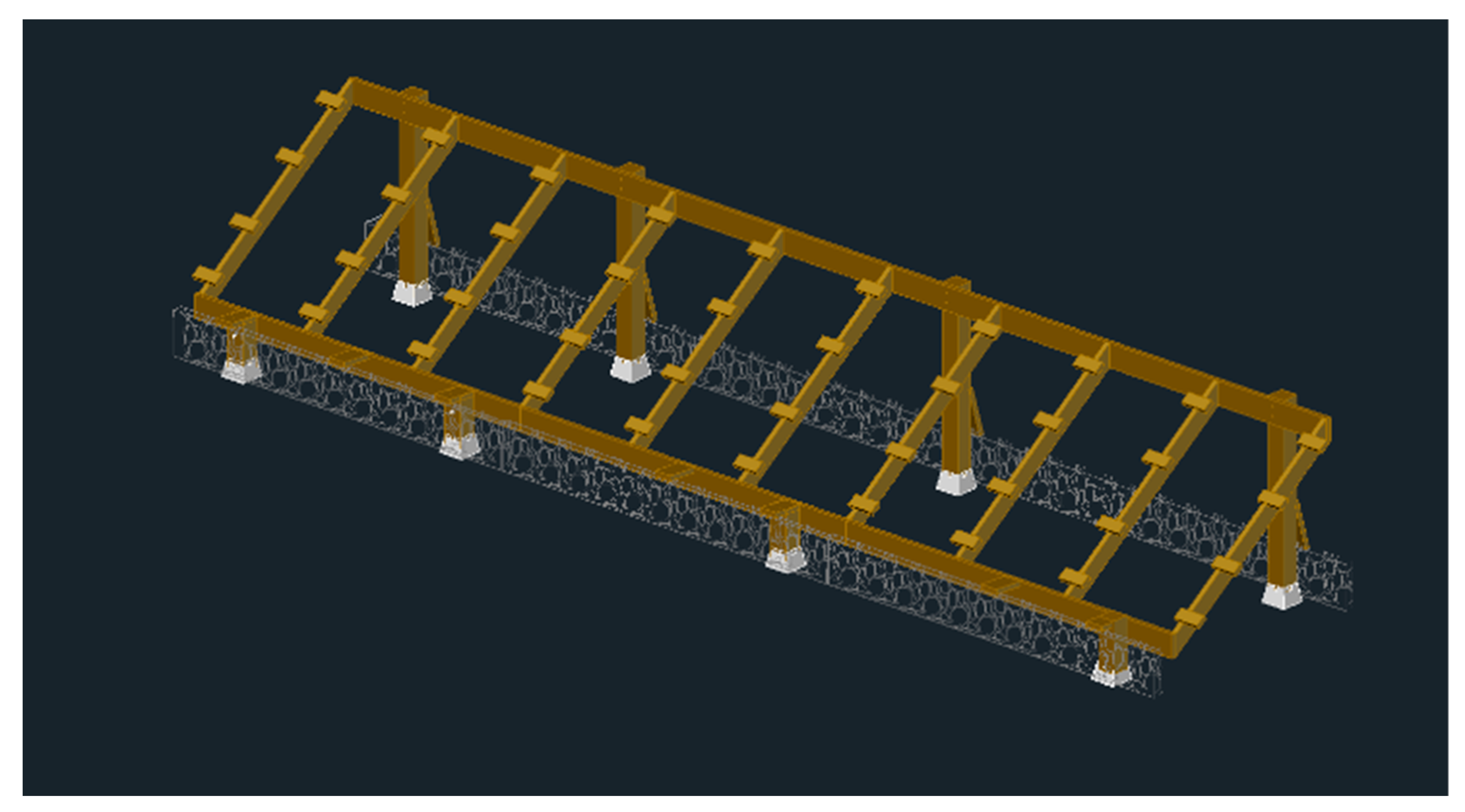
Figure 7.
Variable tilt ballast system.

Figure 8.
Fixed tilt ballast system.

Figure 9.
Rock basket formed using plywood and chicken wire.

Figure 10.
Diagonal connecting to the post and the basket’s plywood.

Figure 11.
Completed ballast foundation.

Figure 12.
Lumber prices [USD] in the U.S. over the last decade [83].
Figure 12.
Lumber prices [USD] in the U.S. over the last decade [83].

Table 2.
Breakdown of the total cost of rocks for the sloped T-shaped ballast system.
| Basket Type | Weight of Rocks Required per Basket [lbs] | Number of Baskets | Cost of Rocks per Basket [CAD] | Total Cost of Rocks [CAD] |
|---|---|---|---|---|
| Inside | 590 | 6 | 14.16 | 113.28 |
| Outside | 295 | 4 | 7.08 | 56.64 |
| Lateral | 45 | 2 | 1.08 | 2.16 |
| Total Cost of Rocks | CAD 172.08 |
Note: This system spans in multiples of two; thus, a six-parking-spot system is used for this analysis.
Table 3.
Breakdown of the total cost of rocks for the variable tilt ballast system.
| Basket Type | Weight of Rocks Required [lbs] | Number of Baskets | Cost of Rocks per Basket [CAD] | Total Cost of Rocks [CAD] |
|---|---|---|---|---|
| Continuous | 1939 | 2 | 46.54 | 93.07 |
| Lateral | 45 | 2 | 1.08 | 2.16 |
| Total Cost of Rocks | CAD 95.23 |
Note: This system spans in multiples of two; thus, a six-parking-spot system is used for this analysis.
Table 4.
A 4 kW sloped T-shaped system bill of materials.
| Member Name | Piece 1 | Cost per Piece 2 | Quantity | Cost [CAD] |
|---|---|---|---|---|
| Joists | 2 × 10 × 8 | 24.92 | 15 | 373.80 |
| Beams | 2 × 10 × 8 | 24.92 | 10 | 249.20 |
| Cross Braces | 2 × 10 × 8 | 24.92 | 2 | 49.84 |
| Posts | 4 × 4 × 8 | 16.78 | 6 | 100.68 |
| Outside Joist Connection | 2 × 4 Fence Bracket | 0.43 | 20 | 8.60 |
| Cross Braces Connection | 2 × 4 Fence Bracket | 0.43 | 20 | 8.60 |
| Middle Joist Connection | 2 × 6 Joist Hanger | 1.82 | 10 | 18.20 |
| Beam to Post Connection | ½″ Carriage Bolt (10″) | 5.37 | 6 | 32.22 |
| Beam to Post Connection | ½″ Nut | 0.79 | 6 | 4.74 |
| Beam to Post Connection | ½″ Washer | 0.80 | 6 | 4.80 |
| Tension Based Connections | 2-1/2″ Brown Deck Screws | 49.99 | 1 | 49.99 |
| Shear Based Connections | 1-1/2″ Joist Hanger Nails | 4.19 | 3 lbs | 12.57 |
| Diagonal From Post to Basket | 2 × 6 × 8 | 12.60 | 6 | 75.60 |
| Superstructure Cost | 988.84 | |||
| Post Block | 4 × 4 Deck Block | 10.45 | 6 | 62.70 |
| Gabion Wire Basket | 1″ × 36″ × 25′ Chicken Wire | 37.99 | 2 | 75.98 |
| Plywood on Gabion Basket | 4 × 8 × 1/2″ Plywood | 71.95 | 1 | 71.95 |
| Gabion Rocks | Large Riverstone (2+″) | 172.08 3 | 1 | 172.08 |
| Foundation Cost | 382.71 | |||
| Total Cost | 1371.55 | |||
| Cost/W | 0.3429 |
1 All lumber is to be pressure treated, and all hardware is to be hot-dipped galvanized. 2 All costs are in Canadian Dollars (CAD) as of 13 October 2023, before tax. 3 Total amount from Table 2.
Table 5.
A 4 kW variable tilt system bill of materials.
| Member Name | Piece 1 | Cost per Piece [CAD] 2 | Quantity | Cost [CAD] |
|---|---|---|---|---|
| Outside Joists | 2 × 6 × 8 | 12.60 | 2 | 25.20 |
| Inside Joists | 2 × 8 × 8 | 18.87 | 9 | 169.83 |
| Beams | 2 × 8 × 10 | 23.58 | 8 | 188.64 |
| Front Posts | 4 × 4 × 10 | 20.99 | 4 | 83.96 |
| Joist to Beam Connection | 2 × 4 Fence Bracket | 0.43 | 22 | 9.46 |
| Back Supports | 2 × 4 × 8 | 7.47 | 10 | 74.70 |
| 2 × 4 Hinges | 8″ Gate Hinges | 16.99 | 10 | 169.70 |
| 4 × 4 to Beam Hinges | 6″ Gate Hinges | 11.99 | 6 | 71.94 |
| Beam to Post Connection | ½″ Carriage Bolt (6″) | 4.44 | 6 | 26.64 |
| Beam to Post Connection | ½″ Nut | 0.79 | 6 | 4.74 |
| Beam to Post Connection | ½″ Washer | 0.80 | 6 | 4.80 |
| Tension-Based Connections | 2-1/2″ Brown Deck Screws | 49.99 | 1 | 49.99 |
| Shear-Based Connections | 1-1/2″ Joist Hanger Nails | 4.19 | 3 lb | 4.19 |
| Superstructure Cost | 883.79 | |||
| Post Block | 4 × 4 Deck Block | 10.45 | 12 | 125.40 |
| Gabion Wire Basket | 1″ × 36″ × 25′ Chicken Wire | 37.99 | 3 | 113.97 |
| Plywood on Gabion Basket | 4 × 8 × 1/2″ Plywood | 71.95 | 1 | 71.95 |
| Gabion Rocks | Large Riverstone (2+″) | 95.23 3 | 1 | 95.23 |
| Foundation Cost | 406.55 | |||
| Total Cost | 1290.34 | |||
| Cost/W | 0.3226 |
1 All lumber is to be pressure treated, and all hardware is to be hot-dipped galvanized. 2 All costs are in Canadian Dollars as of 13 October 2023, before tax. 3 Total amount from Table 3.
Table 6.
Concrete foundation costs for a 4-kW system in CAD.
| System | Number of Bags | Cost per Bag | Total Concrete Cost |
|---|---|---|---|
| T-shaped Fixed Tilt System | 15 | CAD 6.39 | CAD 95.85 |
| Variable Tilt System | 24 | CAD 6.39 | CAD 153.36 |
Table 7.
Comparison between ballast foundation costs and typical concrete foundation costs.
| System | With Ballast Foundation [CAD/W] | With Concrete Foundation [CAD/W] | Percentage Difference |
|---|---|---|---|
| T-shaped Fixed Tilt System | 0.3429 | 0.2712 | 26.4% |
| Variable Tilt System | 0.3226 | 0.2593 | 24.4% |
Table 8.
Comparison between systems with purchased rocks and systems with free rocks.
| System | With Purchased Rocks [CAD/W] | With Free Rocks [CAD/W] | Percentage Difference |
|---|---|---|---|
| T-shaped Fixed Tilt System | 0.3429 | 0.2999 | 14.3% |
| Variable Tilt System | 0.3226 | 0.2988 | 7.9% |
Table 9.
Single line of posts wind load sensitivity analysis.
| System Type | Location | q [kPa] | Weight of Rocks per Basket [lbs] | Percentage Difference |
|---|---|---|---|---|
| Single Line of Posts | London, ON, Canada | 0.47 | 590 | - |
| Toronto, ON, Canada | 0.44 | 552 | −6.4% | |
| Vancouver, BC, Canada | 0.45 | 565 | −4.2% | |
| Halifax, NS, Canada | 0.58 | 728 | +23.4% | |
| Fort Nelson, BC, Canada | 0.30 | 376 | −36.3% | |
| Cape Race, NL, Canada | 1.05 | 1300 | +120.3% |
Table 10.
Double line of posts wind load sensitivity analysis.
| System Type | Location | q [kPa] | Weight of Rocks per Basket [lbs] | Percentage Difference |
|---|---|---|---|---|
| Double Line of Posts | London, ON, Canada | 0.47 | 1939 | - |
| Toronto, ON, Canada | 0.44 | 1777 | −8.3% | |
| Vancouver, BC, Canada | 0.45 | 1820 | −6.1% | |
| Halifax, NS, Canada | 0.58 | 2514 | +29.6% | |
| Fort Nelson, BC, Canada | 0.30 | 1027 | −47.0% | |
| Cape Race, NL, Canada | 1.05 | 5033 | +259.5% |
Table 11.
Single line of posts vertical clearance sensitivity analysis.
| System Type | Clearance [m] | Weight of Rocks per Basket [lbs] | Percentage Difference |
|---|---|---|---|
| Single Line of Posts | 2.0 | 590 | - |
| 1.0 | 295 | −50% | |
| 1.5 | 442 | −25% | |
| 2.5 | 738 | +25% | |
| 3.0 | 885 | +50% |
Table 12.
Double line of posts vertical clearance sensitivity analysis.
| System Type | Clearance [m] | Weight of Rocks per End [lbs] | Percentage Difference |
|---|---|---|---|
| Double Line of Posts | 0.75 | 1939 | - |
| 1.5 | 3385 | +74.5% | |
| 2.0 | 4349 | +124.3% | |
| 2.5 | 5312 | +173.9% | |
| 3.0 | 6276 | +223.7% |
Table 13.
Single line of posts distance between baskets sensitivity analysis.
| System Type | Distance between Baskets [m] | Weight of Rocks per Basket [lbs] | Percentage Difference |
|---|---|---|---|
| Single Line of Posts | 1.5 | 590 | - |
| 1.0 | 944 | −50.0% | |
| 2.0 | 472 | −25.0% | |
| 2.5 | 378 | +25.0% | |
| 3.0 | 314 | +50.0% |
Table 14.
Double line of posts distance between baskets sensitivity analysis.
| System Type | Distance between Baskets [m] | Weight of Rocks per Basket [lbs] | Percentage Difference |
|---|---|---|---|
| Double Line of Posts | 2.0 | 1939 | - |
| 1.0 | 2552 | +31.2% | |
| 1.5 | 2184 | +12.6% | |
| 2.5 | 1776 | −8.4% | |
| 3.0 | 1636 | −15.6% |
Disclaimer/Publisher’s Note: The statements, opinions and data contained in all publications are solely those of the individual author(s) and contributor(s) and not of MDPI and/or the editor(s). MDPI and/or the editor(s) disclaim responsibility for any injury to people or property resulting from any ideas, methods, instructions or products referred to in the content. |
© 2024 by the authors. Licensee MDPI, Basel, Switzerland. This article is an open access article distributed under the terms and conditions of the Creative Commons Attribution (CC BY) license (https://creativecommons.org/licenses/by/4.0/).
Share and Cite
MDPI and ACS Style
Vandewetering, N.; Jamil, U.; Pearce, J.M. Ballast-Supported Foundation Designs for Low-Cost Open-Source Solar Photovoltaic Racking. Designs 2024, 8, 17. https://0-doi-org.brum.beds.ac.uk/10.3390/designs8010017
AMA Style
Vandewetering N, Jamil U, Pearce JM. Ballast-Supported Foundation Designs for Low-Cost Open-Source Solar Photovoltaic Racking. Designs. 2024; 8(1):17. https://0-doi-org.brum.beds.ac.uk/10.3390/designs8010017
Chicago/Turabian StyleVandewetering, Nicholas, Uzair Jamil, and Joshua M. Pearce. 2024. "Ballast-Supported Foundation Designs for Low-Cost Open-Source Solar Photovoltaic Racking" Designs 8, no. 1: 17. https://0-doi-org.brum.beds.ac.uk/10.3390/designs8010017