1. Introduction
The automation field has increased with each year passed in the last decades. It helped in the production and manufacturing process. With the support of automatic systems for food production, feeding capability has increased significantly and its availability tends to sustain large populations. With highly automatized production systems, energy efficiency is optimized and costs are diminished. Automation and remote control of production have increased the manufacturing capability in every sector. It also has improved location tracking, efficiency, and production costs.
Applied measurement and instrumentations for optimizing scanning devices [
1] and digital controllers for highly complex systems (with fuzzy controllers) [
2] are based on electronic equipment and use software programs [
3]. The development of software automated systems for fuel level control supports the investigation of fuel economy and emissions [
4] and the design for supply-to-engine [
5]. Smart control in fuel systems [
6,
7] facilitates powertrain operations [
8], on-board data display [
9], intra-vehicular communication [
10], and economy management [
11]. Vehicular networks may use antennas with multi-sources signals [
12] in transferring data from the electronic control module (ECM) from multiple sources [
13,
14]. With internet services, multiple applications are made available [
15] and specific reports may be structured in Titan Farmis [
16]. Smart control is based on mobile access.
The objective of the paper is the automation of fuel control and data report creation for specific tasks.
2. Material and Method
The paper discusses much more than a system used for monitoring the fuel consumption of agriculture machinery via a software application. It is the greatest opportunity to implement and to test the cloud data transfer for an entire fleet of machinery and vehicles which support remote monitoring and accessibility. In the present paper, the approach of the subject is based on experimental testing and development. Knowing that electronic control may offer a considerable advance in improving the production process efficiency, we are defining here an applied methodology for monitoring the fuel level inside the machineries’ reservoirs to assess values of consumption and energy distribution, using remote accessibility and mobile tracking.
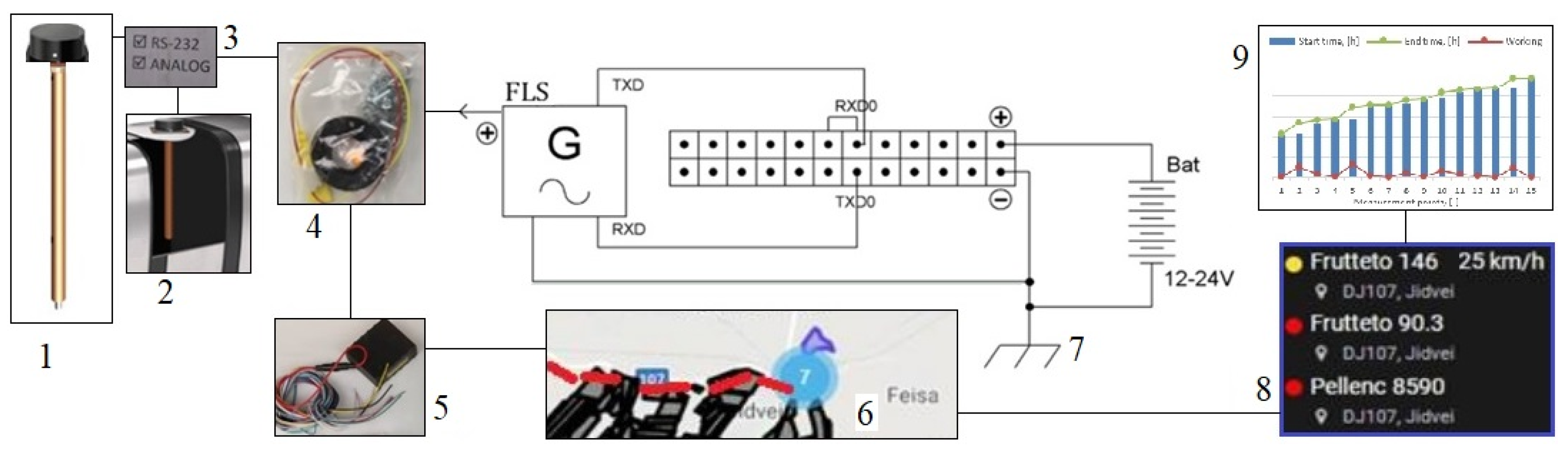
Basic materials and their connections which are applied in the present research are shown in
Figure 1. It offers the implementation details, with specific connections of the Fuel Level Sensor (FLS), as well as the digital graphic interfaces. The applied research presents a practical engineering part, on the one hand, and a substantial scientific or analytical content, on the other hand. This is going to clarify what the present paper intends to show. The schematics and the figures contain some of the captures made when implementing and using the hardware with the software application for the remote control of the machinery. In the present case, the fuel level is not only monitored as a simple measurement to be displayed on board during operation. The study goes further to monitor the actual fuel flow, fuel level, consumption, and efficiency related to the work done by the specific machinery from a remote location. The Fuel Level Sensor (FLS) (1) is the energy supplied from a battery (12–24 V) and placed in the fuel tank (2). It is supported by a volumetric method of determining the fuel level. Through the analog RS 232 interface (3), the signals are sent via electrical linkages (4) to the system’s control unit (5), which transfers the location and operational data to the server (6), to be stored (8) and analyzed (9).
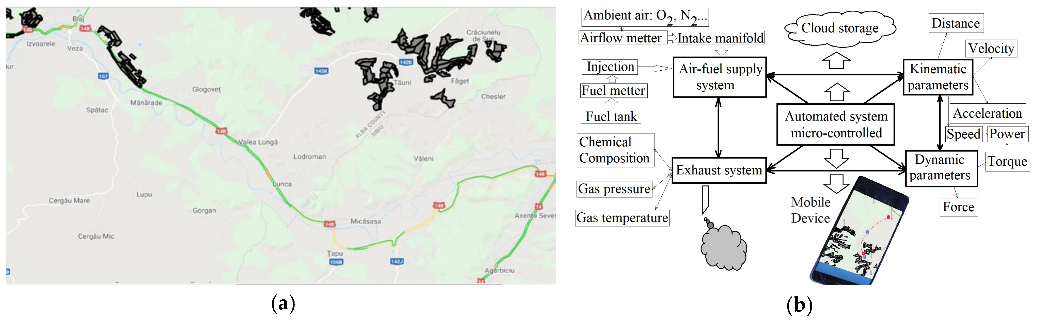
Grounding (7) is important to close the circuit. The methodology is based on the map available in the Titan Farmis application. The latter one is a digital platform that allows the control of an entire fleet of vehicles and machinery in real-time, regarding both kinematic-dynamic aspects and energetic parameters. The methodology is based upon the proper operation of the automated system with a micro-controller, as shown in
Figure 2. These images show and support the implementation methods, communication topologies, software technologies, and services (databases) used during the research.
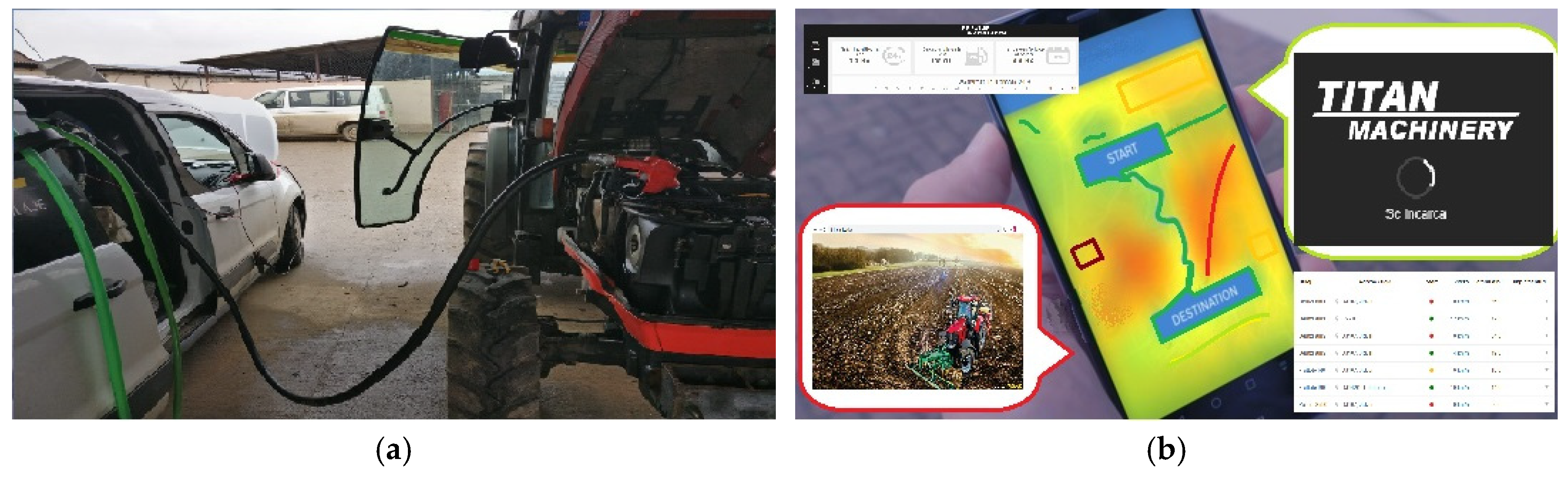
The first basic step in the development of an automated system for fuel tank level control is to set up the specific sensor on the vehicle and connect it to the control unit. Data transfer via a wireless connection is put into practice by using S7 Technology with a Bluetooth Low Energy (BLE) channel. Later ones have a specific type of signal from the DUT-E S7 fuel level sensor. It can be transferred and received by a compatible machinery tracking unit (the one that supports also telematic features) and by any Android equipment. GPS machinery tracking components relate to the fuel level sensors to support precise fuel accounting and to indicate drainages/accidents related to the fuel tank. The fuel level sensors are used for level monitoring in mobile and in stationary units. To realize the machinery location management a web connection is defined and used, as shown in
Figure 3.
Firstly, the components in the machinery supply scheme are configured properly and filled with fuel to cover all the requirements for a specific task and to facilitate at least 8 h of program operation. The method consists of the electro-mechanical engineering practical approach of assembling.
Secondly, the mobile internet connection is established, and actual data are generated to be transferred toward the central server. Basic service set (BSS) and wireless LAN (WLAN) are used.
The total area of operational testing and data generation consists of more than 10 hectares of land which is prepared for the practical campaigns. Support technologies consist of magnetic, conductive, or hall effect for the measuring sensors. Materials and research components are defined in
Table 1.
Frutteto machinery is used to control the fuel system with the automatic system that is realized for this study. The method applied is experimental-digital fuel level monitoring and database creation.
3. Applied Part and Results
The applied part and acquired results of the present work were the experimental data and the electronic management system for remote control of the fuel level measurement. The actual values recorded by the monitoring system in practice are valuable assets for the engineering endeavor validation. The testing protocol for the automatic measuring system of fuel tank level was developed, tested and numerical results were meanwhile acquired for the machinery used in the applied study. The main findings thus consisted of the capability and utility of fast-tracking of every machinery movement and fuel level status. Numerical results were centralized in digital databases and put on post-processing actions.
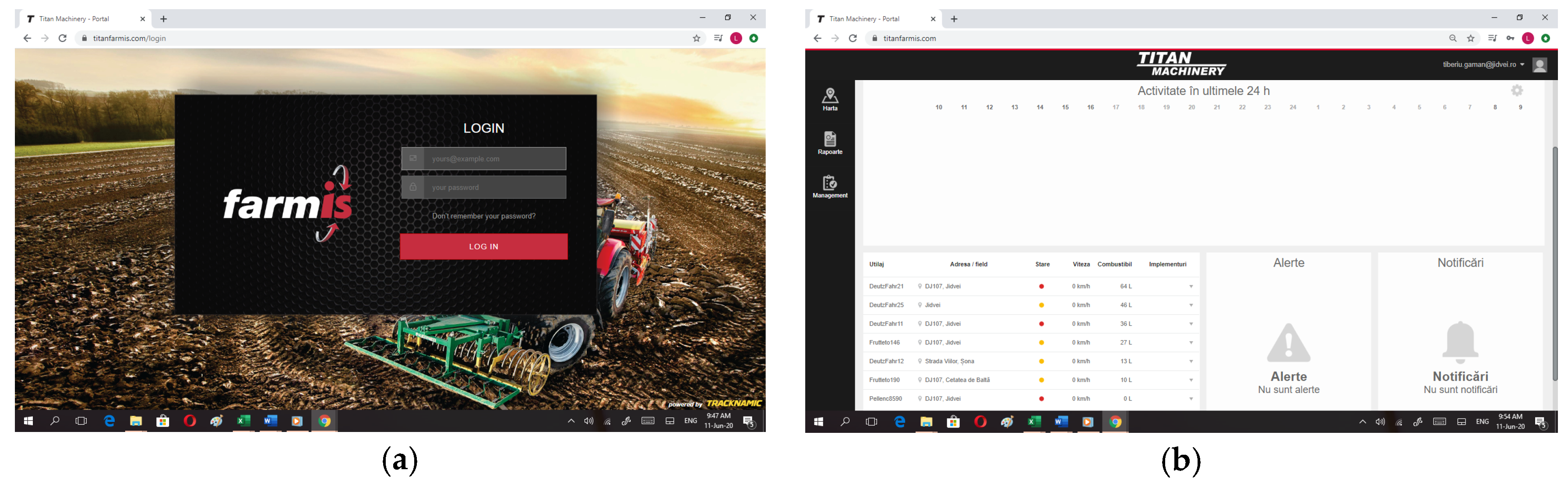
The first step of the system scanning consisted of the login sequence, followed by an activity log check and machine status evaluation, as shown in
Figure 4. Following these steps allowed for the possibility to generate the data files for each machine.
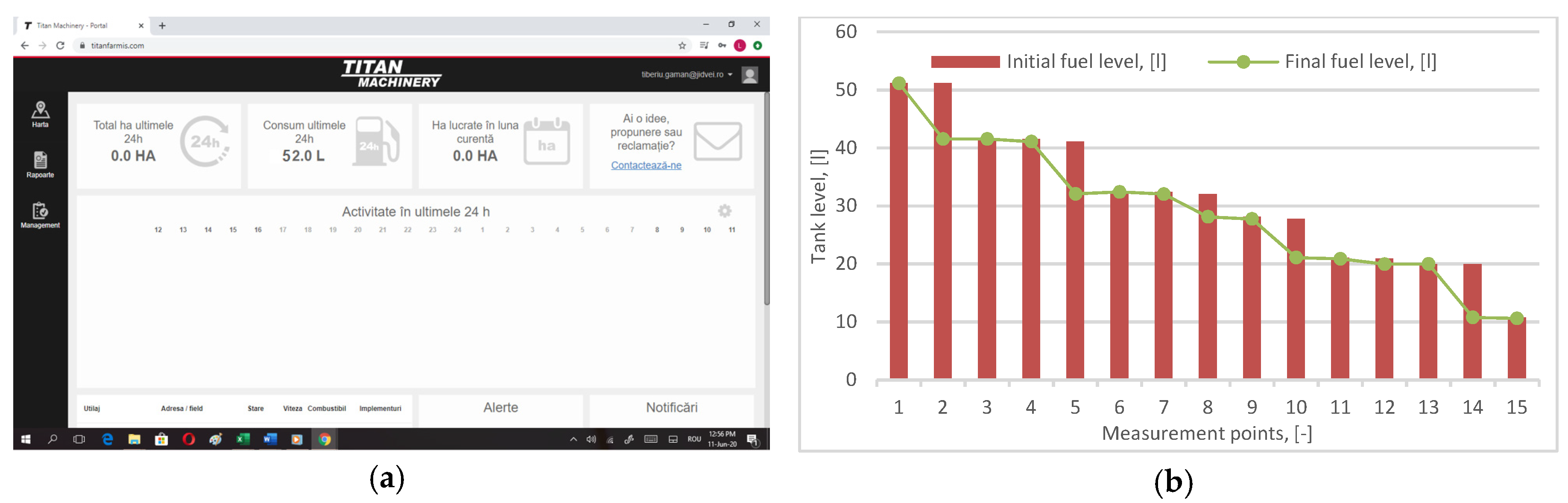
The follow-up steps consisted of detailing the activity available data and actual values monitoring. After the login phase in Titan Farmis and activity brief check, the following sequences were considered to control the consumption and operation status, as shown in
Figure 5.
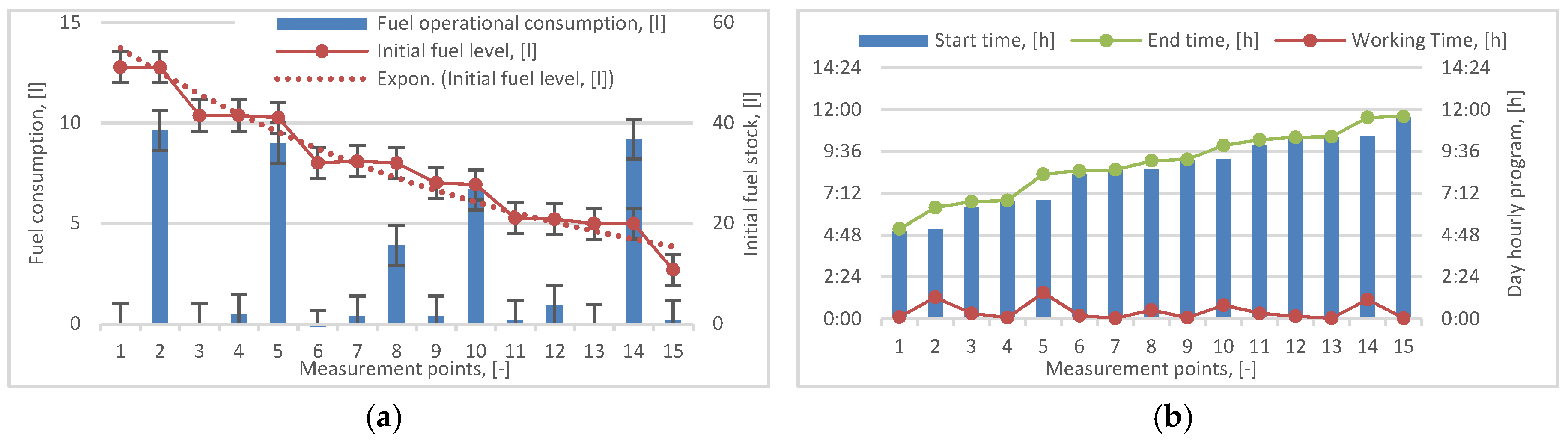
The third step in data digging consisted of fuel measurement and mapping the operating time, as shown in
Figure 6. Graphical representation of data, and mapping, offered an added quality level in process of machine monitoring and management, which was a real scientific contribution.
Differences between the start time and end time somewhat correspond to the bars which represent the fuel consumption in operation. All the data generated within the implemented system were available for post-processing operations to draw maps or to create surfaces.
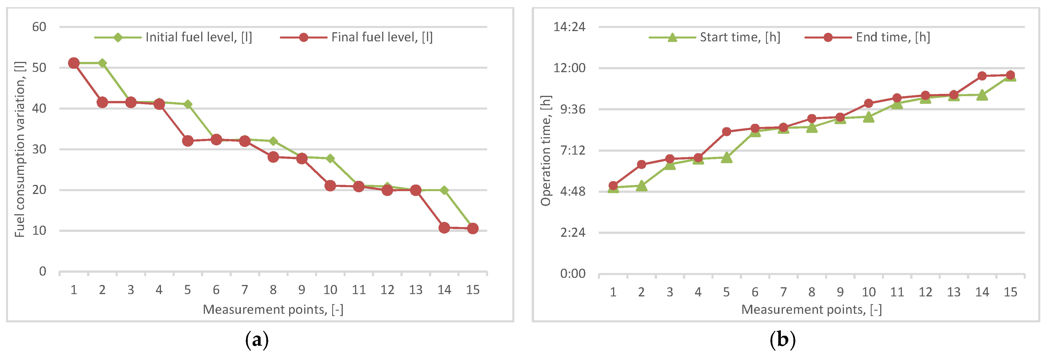
Line variations for fuel level and working time in the field were essential in understanding the evolution and differences between the initial and final values, as shown in
Figure 7.
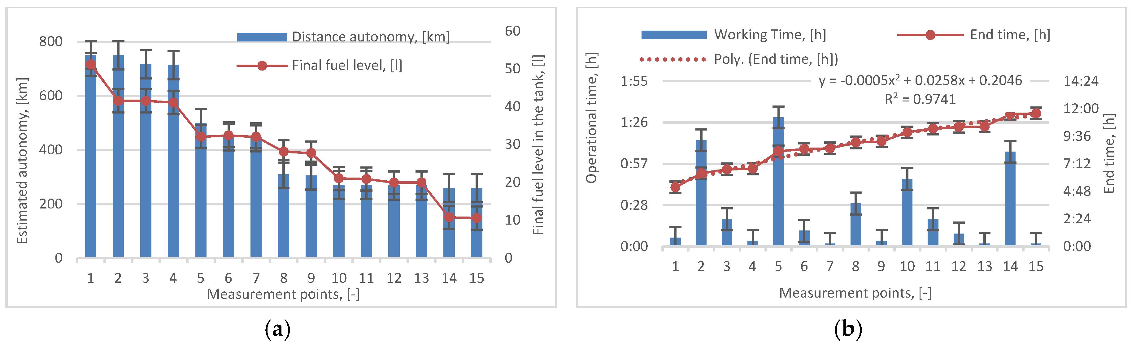
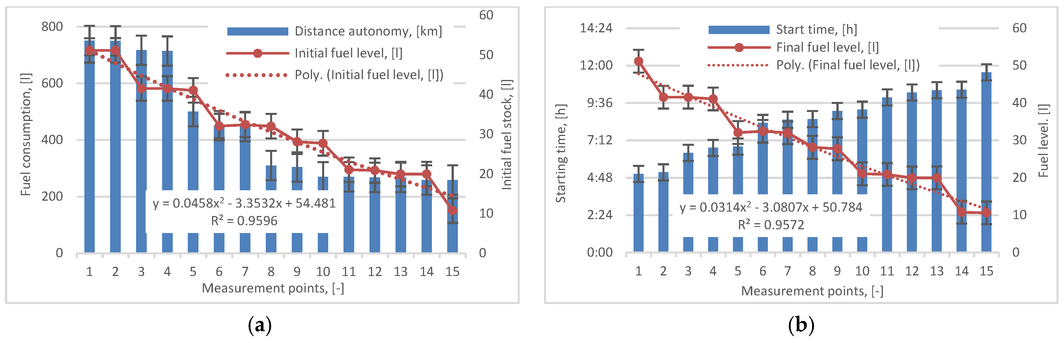
The measurement of the final fuel level and operating time allowed for other calculations such as autonomy and fuel consumption, as shown in
Figure 8.
Appreciation of distance into the reach of fuel autonomy is very important in operation and transport logistics due to optimal programming of routes and travel. The Titan Farmis application and its implements were providing valuable data regarding the real values, as shown in
Figure 9.
Fuel consumption may be also consequently appreciated from the investigation of INITIAL FUEL LEVEL (IFL) evolution curve, which represents the recorded values in the electronic database.
Operating end time (OET) is mathematically defined by the following equation to gain the trendline actual values based on a polynomial model:
where OET is the operating end time during the applied tests; x—specific measurement coefficient (1 … 15).
Initial fuel level (IFL) is mathematically described by the following equation in order to retrieve the trendline numerical values based on the polynomial model:
where IFL is the initial fuel level inside the fuel tank; x—specific measurement coefficient (1 … 15).
Final fuel level (FFL) is mathematically described by the Equation (3) in order to retrieve the trendline numerical values based on the polynomial model:
where FFL is the final fuel level inside the fuel tank; x—specific measurement coefficient (1 … 15).
4. Discussions and Contributions
The important contributions of the authors consist of designing the system that supported the integration of the physical components in the existing machinery fleet, as well as testing the client’s remote access to the database on the server. Other contributions are the specific optimization sequences required for the complete implementation of the system on mobile equipment. Installation of fuel level sensors was also very important for the main objective of the research, and it requested a proper calibration and quality check. In addition, the manufacturing of electrical infrastructure, electronic connections, and digital testing represents a specific contribution. Thus, the most important contribution of the present research is the design and development of an automated system for fuel level control and machinery location tracking which optimized remote accessibility and telematics, as is shown by
Figure 10. Each vehicle from the fleet (1) is sending a data package through a wireless connection (3) to the world wide web (4). The mainframe server (5) stores the data and provides access for the client units. An extensive research unit works with LAN (6) on the Jidvei plant factory for retrieving and processing data recorded from the fleet. A remote researcher unit (7) elsewhere is participating in post-processing the data package. Finally, the remote client unit (8) inspects and verifies the overall results. In this manner, the remote accessibility and up to date telematic system is created. Thus, mobile tracking in a global network is developed and put in operation, providing actual values in real-time.
The significant technical features put into the system are supported by the RS232 interfaces (Frutteto RS), customizable analog and frequency outputs (AF), as well as the CAN J1939 interface. The sensors have a Kline interface, used to configure the complete interaction between them. The RS and CAN sensors have an “alarm” feature for signaling a fuel leak incident. The signal provided by the low-level “alarm” turns on whenever the fuel level drops below a preset value. The sensors determine the level of fuel as well as other liquids (if necessary, such as cooling liquid). These solid-state fuel, coolant, or oil level sensors generate a continuous signal regarding the monitored tank content level and operate either voltage or resistance formats. The sensor unit will be automatically re-calibrated every time the fuel tank is refilled. It can work properly even when mixtures of conventional fuels and additives are included. Available sizes are suitable for every tank depth in a range between 190 mm and 1000 mm. The length of the sensor may also be adjusted to the proper size adapted for each practical application. In addition, there is provided a built-in display and accelerometer to facilitate measurements on all types of rough terrains. Compared to other achievements, such as [
9,
10,
11,
12,
13], this one is offering both remote tracking, fuel monitor, and kinematic recording at distance. The discussion over the main contributions and achievements of the present research creates the opportunity for issuing conclusive ideas regarding the practical implements and the recorded results.
5. Final Observations and Conclusions
Automatic systems and smart interfaces in production and logistics are key factors for development. They constitute some of the most significant research subjects in mechatronics and robotics nowadays. The applied research and testing are supporting the automatic system development with a high level of control and monitoring procedures for speed, location, tilled area, fuel economy, and energy efficiency integrated into a smart program available on mobile devices.
It may be quite easily observed that the implemented system has the operational capacity and provides actual data in real-time for multiple geo-locations regarding fuel level monitoring and precise global positioning. Tank fuel level sensors transmit data through GPS connections during operation and stationary periods. The accurate measurement of the level inside the fuel tank contributes to the optimization of the time and geo-location of re-fills, as well as the prevention of fuel leaks. The fuel level sensor makes accurate measurements of the amount of fuel in the tank, and it is compatible with the machinery telematics systems and data managing equipment (both hardware and software). Accessing databases of different pieces of machinery may support a better assessment of their performance and energy consumption in order to define energy costs and financial impact.
The automation of data recording about tank fuel levels and of the data storage system allows the admin account to have remote access to the controlled machinery, including checking their status.
The development of the automated system for fuel tank level control has been realized according to the initially proposed objective and it allowed the practical setups on specific machinery, as well as manufacturing the technical solutions for integrating all necessary components.
Actual data have been received remotely by the WLAN connection supported by the machinery location management system that was put in place during the experimental setup operation. Thus, these were taken into consideration and optimization procedures were realized for accessibility level and mobile tracking, showing the precise location, GPS coordinates, tilled area for tractors, and traveling speed.
Further research is expected to define more accurately the topic of automation for remote machinery operation. As other similar technologies will be used more, comparison studies will be done.
Author Contributions
Conceptualization, D.P. and D.-L.B.; methodology, A.-I.B.; software, D.P.; validation, D.P., D.-L.B. and A.-I.B.; formal analysis, D.-L.B.; investigation, D.P.; resources, A.-I.B.; data curation, D.-L.B.; writing—original draft preparation, D.P.; writing—review and editing, D.-L.B.; visualization, D.-L.B.; supervision, D.P.; project administration, A.-I.B.; funding acquisition, A.-I.B. and D.P. All authors have read and agreed to the published version of the manuscript.
Funding
This research received funding from the Research and Innovation Ministry, CCCDI-UEFISCDI, through PN-III-P2-2.1-CI-2018-1227 Grant—PNCDI III.
Acknowledgments
Lab support was provided by SC Maria Turism SRL, Jidvei Company.
Conflicts of Interest
The authors declare no conflict of interest.
References
- Andrei, L.; Băldean, D.L.; Borzan, A.I. Applied Measurements and Instrumentation for Improving Diagnostic Devices and Systems in Metropolitan Polluted Environments with Nitric and Carbon Oxides. In Proceedings of the 6th International Conference on Advancements of Medicine and Health Care through Technology, Cluj-Napoca, Romania, 17–20 October 2018; Vlad, S., Roman, N., Eds.; Springer: Singapore, 2019; Volume 46, pp. 45–49. [Google Scholar] [CrossRef]
- Baghli, F.Z.; El bakkali, L.; Lakhal, Y. Multi-input Multi-output Fuzzy Logic Controller for Complex System: Application on Two-links Manipulator. In Proceedings of the 8th International Conference Interdisciplinarity in Engineering, INTER-ENG 2014, Tirgu Mures, Romania, 9–10 October 2014; pp. 607–614. [Google Scholar] [CrossRef]
- Băldean, D.L. Software for the study of some parameters of gasoline injection process in Otto engines. J. Acta Tech. Napoc. Appl. Math. Mech. 2018, 6, 70–78. [Google Scholar]
- Borza, E.V.; Băldean, D.L.; Borzan, A.I. Research Concerning Fuel Economy Coefficient and Carbon Footprint in Various Conditions for a City Compact Size Vehicle with Digital Control for a Green Solution and Method at Technical University from Cluj-Napoca. In Proceedings of the 4th International Congress of Automotive and Transport Engineering, Cluj-Napoca, Romania, 30 September 2018; Burnete, N., Varga, B., Eds.; Springer: Cham, Switzerland, 2018; Volume 46, pp. 181–189. [Google Scholar] [CrossRef]
- Borzan, A.I.; Băldean, D.L. Experimental design for Diesel supply control in order to improve fuel efficiency. IOP Conf. Ser. Mater. Sci. Eng. 2019, 568. [Google Scholar] [CrossRef]
- Borzan, A.I.; Băldean, D.L. The Development of a New Interface for Intelligent Control of Energy Supply in Dynamic Environment with Process Digitization. In Proceedings of the 13th International Conference Interdisciplinarity in Engineering, INTER-ENG 2019, Tirgu Mures, Romania, 4 October 2019; Volume 46, pp. 1–6. [Google Scholar] [CrossRef]
- Chereches, A.I.; Băldean, D.L.; Borzan, A.I. Research of Intelligent Control of Injection Systems for Subaru Competition Car. In Proceedings of the 30th SIAR International Congress of Automotive and Transport Engineering, SMAT 2019, Craiova, Romania, 14 October 2019. [Google Scholar] [CrossRef]
- Jovrea, S.; Băldean, D.L. Experimental Research of Electronic Diesel Control (EDC) System Operation in Relation with N47 Engine Load from BMW 320D (E90) Automobile at Constant Temperature and Speed. 2018, Volume 33. Available online: http://stiintasiinginerie.ro/33-43 (accessed on 15 June 2020).
- Jovrea, S.; Borzan, A.I.; Băldean, D.L. Researching on-Board Display of Essential Information Concerning Technical Conditions in Operation and Fuel-Economy of a Motor-Vehicle in Operation. Știință și Inginerie 2017, 31. Available online: http://stiintasiinginerie.ro/31-67 (accessed on 15 June 2020).
- Jovrea, S.; Băldean, D.L. Researching the Implementation at on-Board Level of Mercedes e Class Coupe Vehicles of Essential Information Concerning Fuel-Economy in Operation. 2018, Volume 33. Available online: http://stiintasiinginerie.ro/33-62 (accessed on 15 June 2020).
- Jovrea, S.; Jovrea, D.L.; Crisan-Lupa, L.V. Researching the Economy of Mercedes e Class Coupe Limo in Operation. 2019, Volume 35. Available online: http://stiintasiinginerie.ro/35-42 (accessed on 16 June 2020).
- Kaabal, A.; El halaouia, M.; El Jaafarib, B.; Ahyoudc, S.; Asselman, A. Design of EBG antenna with multi-sources excitation for high directivity applications. In Proceedings of the 11th International Conference Interdisciplinarity in Engineering, Tirgu Mures, Romania, 5–6 October 2017; Volume 22, pp. 598–604. [Google Scholar] [CrossRef]
- Marincaș, C.; Băldean, D.L.; Kocsis, L.B.; Borzan, A.I. Contribuții la cercetarea experimentală a funcționalității modulului electronic diesel control (EDC) în raport cu alimentarea de la motorul N47 de la automobilul BMW 320D (E90). 2017. Available online: http://stiintasiinginerie.ro/31-82 (accessed on 16 June 2020).
- Moldovan, A.; Băldean, D.L. Borzan, Experimental Research of the Management System from the Peugeot 4007 Sport Utility Vehicle. 2017; Volume 31. Available online: http://stiintasiinginerie.ro/31-71 (accessed on 16 June 2020).
- Turc, T. Using WEB Services in SCADA Applications. In Proceedings of the 8th International Conference Interdisciplinarity in Engineering, Tirgu Mures, Romania, 9–10 October 2014; Volume 19, pp. 584–590. [Google Scholar] [CrossRef]
- Titan Farmis. Available online: https://titanfarmis.com/ (accessed on 16 June 2020).
- Bosch—Bessere Luftqualität und Individuelle Mobilität. Available online: https://www.youtube.com/watch?v=XU23yfjb780 (accessed on 16 June 2020).
| Publisher’s Note: MDPI stays neutral with regard to jurisdictional claims in published maps and institutional affiliations. |
© 2020 by the authors. Licensee MDPI, Basel, Switzerland. This article is an open access article distributed under the terms and conditions of the Creative Commons Attribution (CC BY) license (http://creativecommons.org/licenses/by/4.0/).


