Force Amplification Mechanism for Increased Stroke and Speed Responses of Piezoelectric Stick-Slip Miniaturized Linear Motor †

Mechanical and Medical Engineering Department, Furtwangen University, Robert-Gerwig-Platz 1, 78120 Furtwangen, Germany
†
Presented at the First International Electronic Conference on Actuator Technology: Materials, Devices and Applications, 23–27 November 2020; Available online: https://iecat2020.sciforum.net/.
Proceedings 2020, 64(1), 17; https://0-doi-org.brum.beds.ac.uk/10.3390/IeCAT2020-08518
Published: 21 November 2020
(This article belongs to the Proceedings of The 1st International Electronic Conference on Actuator Technology: Materials, Devices and Applications)
Abstract
:In this paper, a mechanical system model based on Simulink software was developed for a proposed design for a stick-slip motor. Only the orientation of a cubic PZT element identifies the mode configuration of the motor. The preliminary results showed that force amplification mode exhibited roughly five times more speed, at one-hundred times more loading force, compared to the displacement amplification mode. Interestingly, when the output displacement was compared to maximum expansion of mechanical advantage mechanism, then the force amplification mode showed displacement amplification.
1. Introduction
Piezoelectric motors are commonly available as ultrasonic, walking and inertia motors [1]. The inertia, or the stick-slip motors, are commonly applied in positioning applications, where the required actuation force is low if not negligible [1] (p. 6). The force actuation level depends mainly on the core element of the motor; the piezoelectric material, which is normally available as multilayer stack, made of lead-zirconate-titanate (PZT) ceramics. For example, the commercial PZT stack PA3JEW from Thorlabs Inc. has a 360 N blocking force, where the free stroke displacement is 2 µm, which is a 2% of the PZT thickness.
In stick-slip motor, a mechanism holds the PZT element such that long displacement is achieved through accumulation of repeated strokes of the PZT. Motor mechanisms based on mechanical advantage design exhibit displacement amplification of the PZT stroke, thus enhancing of the motor speed. The structural design of mechanical advantage mechanism can be realized in various forms, such as lever [2], asymmetric flexure hinge [3], or oval shell [4,5]. Lever and flexure hinge designs are fragile mechanisms and require a precision manufacturing technology process, especially when miniaturization is a critical application requirement. On the other hand, the shell shape is more compact and reliable design.
Due to the fundamental physics of mechanical advantage, displacement amplification definitely causes a specific force attenuation, which, in turn, limits the motor capacity in terms of load actuation. For example, the applied PZT stack AE0505D16F from Thorlabs has, at 100 V, a blocking force of 850 N and a free stroke of 11.6 µm. This displacement could be amplified using the asymmetric flexure hinge to roughly 225 µm, when the motor was loaded by 4.5 N [3] (p. 6519). The resulting force attenuation in the mechanical advantage can be overcome by achieving a larger size PZT stack; however, a larger size motor will be produced. In applications, such as medical implant motors, large force actuation and miniaturized motor scale are required; therefore, the force attenuation due to displacement amplification will be a critical design challenge.
In the following section, a new design methodology is discussed as an approach for creating a stick-slip piezoelectric motor with amplified force and increased stroke actuation response. The performance of the stick-slip motor, based on mechanical advantage in Force Amplification Mode (FAM) configuration, was investigated and compared to the performance of the conventional Displacement Amplification Mode (DAM).
2. Methods
2.1. New Design Methodology Approach
In stick-slip motor, the total actuated-displacement consists of two components. The first component results from the mechanical expansion of the mechanical advantage mechanism, after the mechanical deformation of the PZT element. The other component is an extended displacement, which results from the position-translation of the mechanical advantage mechanism, due to the gained acceleration of the moving slipping mass. This gained acceleration, or the transferred kinetic energy of the moving slipping mass depends on the released elastic energy of the mechanical advantage mechanism, such that the larger the stored elastic energy, the larger the transferred kinetic energy.
2.2. Structural Design
The stick-slip motor consists mainly of piezoelectric actuator, mechanical advantage mechanism, inertial mass, slipping mass and mechanical holder. The displacement amplification mode (DAM) design is shown in Figure 1a. The PZT stack is inserted in the center of the folded structure, the mechanical advantage mechanism. The PZT applies forces on the long axis of the mechanism, where inertial mass (large size structure) and the slipping mass (bar structure) are placed at the short axis of the mechanism. The mechanical holder, which holds the sliding mass, is not shown in the figure for the simplicity of presentation.
The force amplification mode (FAM) design is shown in Figure 1b. In this mode, the placement of the inertial and slipping masses are reciprocated compared to the DAM design. Additionally, the applied force of the PZT is on the short axis. In order to apply a reasonable comparison between the DAM and FAM designs, identical dimensions of the mechanism and PZT elements were considered.
2.3. System Modelling and Boundary Conditions
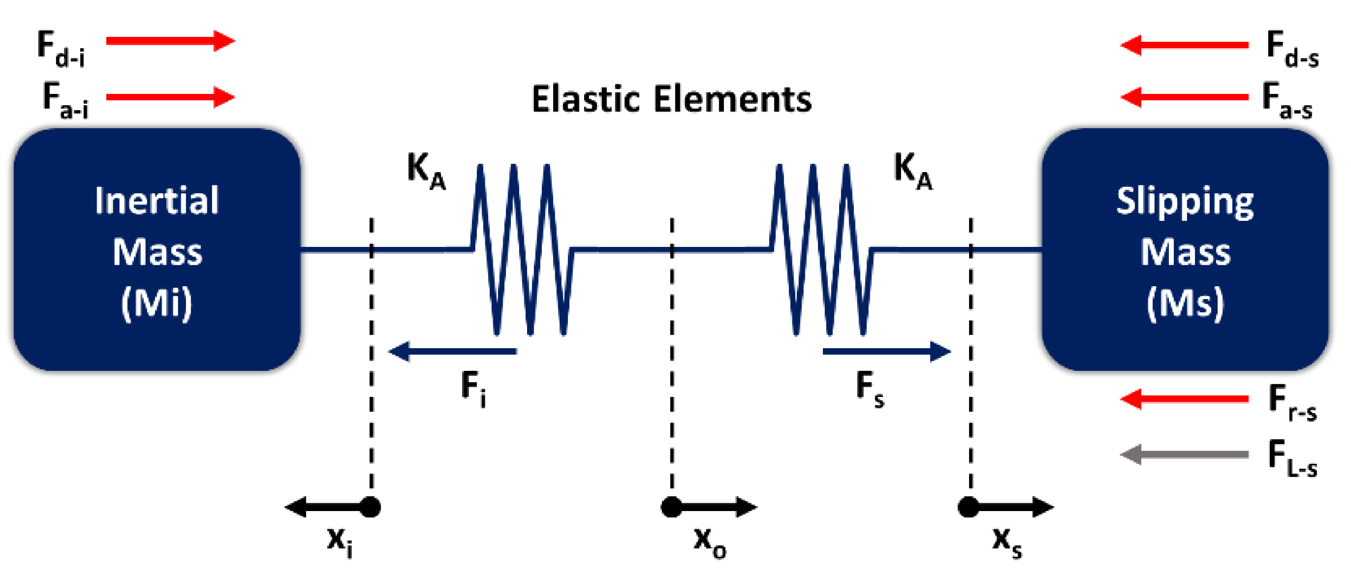
For both DAM and FAM designs, the system can be represented by two coupled oscillating masses, as shown in Figure 2. The coupled masses and the elastic elements represent the inertial and slipping structures, and the mechanical advantage mechanism, respectively. The common point (Xo) between elastic elements is the point at which the PZT element is placed. The points (Xi) and (Xs) can have different magnitude depending on the oscillation response of the corresponding masses. The displacement actuation is the final value of (Xs).
The model is initially set in the compressed mode, representing the status at which the PZT element is applying actuation force. Therefore, both elastic elements are initially compressed to the maximum actuator displacement (SA), and therefore elastic energy is initially stored in each elastic element. At the moment, when the PZT element is switched off, an impulse response is assumed. In this case, elastic energy will be released and appear as moving the masses. In terms of system forces, acceleration, damping and elastic forces will result on each side of the motor—inertial and slipping sides. However, on the slipping side of the motor, further force components were considered—the mechanical friction force, due to the mechanical holder effect on the slipping part, and the mechanical loading force, due to the actuated object. Assuming we neglect the damping effect, the common point (Xo) and acceleration of the inertial and slipping masses (ai, as) of the system can be mathematically represented by the following equations:
The parameter values of stiffness constant (KA) and initial displacement (SA) of elastic elements depend on the structural design of the mechanical advantage mechanism and the electromechanical characteristics of the applied PZT element. In this work, the focus is on comparing performances between the DAM and FAM stick-slip motors, regardless of the specific structural design of the mechanical advantage mechanism.
A mechanical advantage mechanism has two ports—an input port where effort is applied and represented by force (FE) and displacement (SE); an output port, where the mechanical load is applied and represented by force (FL) and displacement (SL). The mechanical advantage (β) can then be represented by:
As previously stated, the input and output ports of the FAM design are reciprocated, compared to the DAM design. Therefore, if the FAM design is represented by:
then the DAM design is represented by:
The Simulink model in Figure 3 was implemented to extract the system response represented by the mathematical equations above. For this model, a slipping mass (Ms) of 0.2 g and inertial mass (Mi) of 2 g were considered for both the FAM and DAM designs. The mechanical advantage is 10. A PZT element with 1.25 μm stroke at 125 N generated force was arbitrarily assumed. Accordingly, the SA and KA values are 0.125 μm and 10 GN/m for the FAM, and 12.5 μm and 1 MN/m for the DAM.
3. Results and Discussion
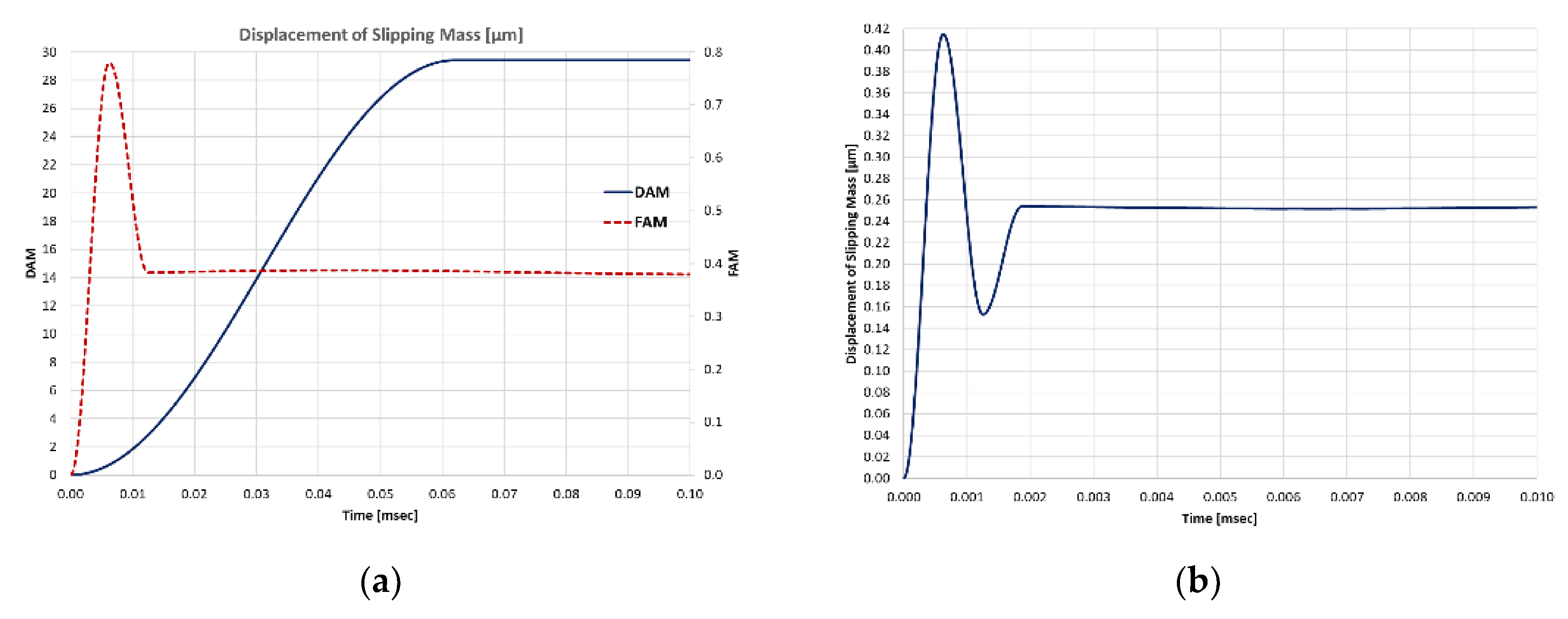
The dynamic mechanical response of the FAM and DAM designs in Figure 4a is the resultant displacement of the slipping mass after switching of the PZT element. In this case, the friction force was set to 5 N. In Figure 4b, the response was extracted for the FAM design at friction force of 200 N, where the DAM design did not respond at the same conditions due to the friction force being too large.
The FAM response shows an impulse response before it goes in steady state. This impulse response represents a displacement amplification due to the accelerated slipping mass. However, due to oscillation of the slipping mass, that displacement amplification is decreased to the steady state level, which is actually the resultant displacement due to the mechanical deformation of the elastic element. Such a response was not observed in the case of DAM. The velocity of the slipping mass achieved 1.044 m/s at the peak of the impulse in the case of FAM. For the DAM case, no movement was observed at a 200 N friction force. However, at 2 N friction force, the observed velocity was 0.2263 m/s.
This result should be further investigated to study the effect of applying a specific control signal to hold the slipping mass at the peak of the impulse before it decreases down. Additionally, further design optimization of the inertial and slipping masses might result in the further improvement in the displacement amplification of the FAM design.
4. Conclusions
The force amplification mode (FAM) stick-slip motor has the advantage of larger force actuation compared to displacement amplification mode (DAM). In this work, the dynamic response of the FAM showed that, due to mass acceleration, displacement amplification is still possible; however, at the transient phase. Further design optimization of the inertial and slipping mass, and the application of the specific control signal should be investigated to improve FAM displacement amplification.
Acknowledgments
This project is funded by the Federal Ministry of Education and Research (BMBF) in Germany under the umbrella of Connected Health in Medical Mountains (CoHMed) of Furtwangen University with grant number 13FH5I01IA.
Conflicts of Interest
The founding sponsors had no role in the design of the study; in the collection, analyses, or interpretation of data; in the writing of the manuscript, and in the decision to publish the results.
References
- Hunstig, M. Piezoelectric Inertia Motors—A Critical Review of History, Concepts, Design, Applications, and Perspectives. Actuators 2017, 6, 7. [Google Scholar] [CrossRef]
- Huang, W.; Sun, M. A Design, Analysis, and Experiment on a Novel Stick-Slip Piezoelectric Actuator with a Lever Mechanism. Micromachines 2019, 10, 863. [Google Scholar] [CrossRef]
- Lu, X.; Gao, Q.; Li, Y.; Zhang, X.; Qiao, G.; Cheng, T. A Linear Piezoelectric Stick-Slip Actuator via Triangular Displacement Amplification Mechanism. IEEEA Access 2020, 8, 6515–6522. [Google Scholar] [CrossRef]
- Ragonet, M.; Petiniot, J.-L.; Fournier, M.; Porchez, T.; Sosnicki, O.; Bouchet, C. Potentialities of APA Composite Shell Actuators and SA75D Amplifier for New Dynamic Applications. In Proceedings of the 15th International Conference on New Actuators, Bremen, Germany, 13–15 June 2016. [Google Scholar]
- Guignabert, A.; Pages, A.; Freychet, O.; Barillot, F.; Stentz, J.; Belly, C.; Maillard, T.; Claeyssen, F. Improvement of MSPA: Module of Stepping Piezo Actuator. In Proceedings of the 16th International Conference on New Actuators, Bremen, Germany, 25–27 June 2018. [Google Scholar]
Figure 1.
Stick-Slip piezoelectric motor design based on: (a) displacement amplification mode (DAM); (b) force amplification mode (FAM).
Figure 1.
Stick-Slip piezoelectric motor design based on: (a) displacement amplification mode (DAM); (b) force amplification mode (FAM).

Figure 2.
Mass-spring model of stick-slip piezoelectric motor.

Figure 3.
Simulink block diagram of the mechanical model of the stick-slip motor.

Figure 4.
Dynamic response: (a) DAM and FAM responses under friction force of 5 N, (b) FAM response under friction force of 200 N.
Figure 4.
Dynamic response: (a) DAM and FAM responses under friction force of 5 N, (b) FAM response under friction force of 200 N.

Publisher’s Note: MDPI stays neutral with regard to jurisdictional claims in published maps and institutional affiliations. |
© 2020 by the author. Licensee MDPI, Basel, Switzerland. This article is an open access article distributed under the terms and conditions of the Creative Commons Attribution (CC BY) license (https://creativecommons.org/licenses/by/4.0/).
Share and Cite
MDPI and ACS Style
Kloub, H. Force Amplification Mechanism for Increased Stroke and Speed Responses of Piezoelectric Stick-Slip Miniaturized Linear Motor. Proceedings 2020, 64, 17. https://0-doi-org.brum.beds.ac.uk/10.3390/IeCAT2020-08518
AMA Style
Kloub H. Force Amplification Mechanism for Increased Stroke and Speed Responses of Piezoelectric Stick-Slip Miniaturized Linear Motor. Proceedings. 2020; 64(1):17. https://0-doi-org.brum.beds.ac.uk/10.3390/IeCAT2020-08518
Chicago/Turabian StyleKloub, Hussam. 2020. "Force Amplification Mechanism for Increased Stroke and Speed Responses of Piezoelectric Stick-Slip Miniaturized Linear Motor" Proceedings 64, no. 1: 17. https://0-doi-org.brum.beds.ac.uk/10.3390/IeCAT2020-08518