Proceeding Paper

Modeling and Simulation of an Array of Dielectric Elestomeric Actuator Membranes †

1
Department of Systems Engineering, Department of Materials Science and Engineering, Saarland University, 66123 Saarbruecken, Germany
2
Department of Sensors and Thin Films, University of Applied Sciences of Saarland, Goebenstraße 40, 66117 Saarbruecken, Germany
3
Center for Mechatronics and Automation Technologies (ZeMA) gGmbH, 66121 Saarbruecken, Germany
*
Author to whom correspondence should be addressed.
Presented at the First International Electronic Conference on Actuator Technology: Materials, Devices and Applications, 23–27 November 2020; Available online: https://iecat2020.sciforum.net/.
Published: 20 November 2020

Abstract

:
Recent advances in miniaturized actuators and sensors have enabled the development of cooperative systems, in which a complex global task is achieved through the joint collaboration of several microunits. Achieving system miniaturization while maintaining the desired actuation/sensor and cooperative functionality, however, is generally quite challenging from a practical point of view. Smart material transducers based on dielectric elastomer (DE) membranes represent a technology with great potential for the design of high-performance microactuator systems. By designing a miniaturized array of DE taxels, their simultaneous actuation and sensing capabilities can be used to develop large deformation, energy-efficient, multi-functional, and cooperative systems. In addition, the high flexibility of DE material makes the developed system highly suitable for new application fields, such as wearables and soft robotics. To properly design, optimize, and control cooperative DE systems, accurate mathematical models need to be developed first. In this paper, we present a novel physics-based model for an array of three DE actuator taxels. Such a model represents the first step towards the development, optimization, and control of a complex cooperative matrix actuator. Through the proposed model, it is possible to describe the coupling existing between the DE elements, and predict how such coupling effects influence the complete system performance. After presenting the model, the effect of geometrical parameters on the spatial coupling response is studied by means of numerical simulations.

1. Introduction

A Dielectric elastomer (DE) transducer consists of an elastomer film sandwiched between two compliant electrodes. DEs can be effectively used as actuators, because they transform electrical energy into motion. By applying a high voltage to the electrodes, a Maxwell stress is generated in the membrane, which results in a thickness reduction and in subsequent area expansion [1]. Furthermore, due to the correlation existing between deformation and electrical capacitance, DEs can also function as sensors. In recent years, DEs have gained significant popularity thanks to their numerous advantages, such as high deformation (on the order of 100%), high flexibility, being lightweight, energy efficiency, low cost, and self-sensing (i.e., they can work as actuators and as sensors at the same time) [1]. Nowadays, DEs appear as a very promising technology well suited for both for industrial applications (e.g., industrial valves [2,3] or pumps [4,5]) as well as less conventional ones (e.g., loudspeakers [6,7], soft robots [8,9,10], braille displays [11,12], medical robots [13], and artificial muscles [14], to mention a few examples).
Despite a number of DE applications being successfully developed and validated, up to now they are mostly operated at the macroscale level. Only a few examples of microscale DE devices have been recently presented—e.g., [15]. This general lack of microscale DE systems is mainly due to many practical issues encountered during the miniaturization process. In fact, scaling a DE device while maintaining the desired actuation/sensing functionality and flexibility, presents a number of practical and technological challenges. It is remarked how, up to date, many of these issues are still present. Once DE microtechology is properly investigated and understood, it will allow the design of a new generation of microrobots, micro-optical systems, and wearable devices, possibly capable of intelligent and cooperative features. To effectively understand and optimize such cooperative DE microactuators, accurate models and simulation tools play a key role. Due to the highly nonlinear behavior of the material, however, modeling of complex DE structures is generally highly involved. In addition, the geometric nonlinearities, the electromechanical coupling, and the neighbor effects that exist between adjacent elements in an array actuator further complicate the overall analytical description. We remark, however, that the state-of-the-art literature severely lacks systematic investigations on modeling and performance scalability for cooperative and small-scale DE systems.
As a first step in this field, in this paper we present the preliminary development of a physics-based model for a cooperative DE structure. The system under investigation consists of three DE actuator (DEA) elements arranged in an array configuration. By properly controlling the different membranes, cooperative actuation/sensing features can be effectively implemented. The development of a model which can be used for system analysis, simulation, and control represents a fundamental step towards this goal. The proposed physics-based model takes into account the kinematic nonlinearities due to geometry and boundary conditions, together with the electromechanical coupling existing between the DEA taxels. These interactions depend on various design parameters, such as the size of the individual membranes, their relative spacing, as well as the mechanical pretensioning mechanism. After developing the constitutive equations, a numerical study is performed in order to understand the relationship between several design parameters (e.g., geometry, prestretch, mechanical bias) and the behavior of the considered array, focusing on the quasi-static actuation performance.
The remainder of this paper is organized as follows. In Section 2, a simulation model for an array of three actuators composed by DE membranes (DEAs) is developed. Then, in order to understand the relationship between the geometry and the behavior of the overall system, a parameter study is conducted in Section 3. Finally, concluding remarks are discussed in Section 4.

2. Methods

This section presents the model of an array of three DEA elements. Figure 1 reports a top-view sketch of such a system. A cross-sectional depiction of the array is illustrated in Figure 2, based on the section determined by the dashed line in Figure 1.
The system consists of three circular DE membranes (depicted in black) printed on a passive silicone membrane (depicted in brown). The left- and right-hand sides of the passive silicone membranes are rigidly clamped to a fixed frame (not shown in Figure 1). Each DEA is preloaded out-of-plane with a biasing mechanism—i.e., a precompressed linear spring. The deformation of the actuators is guided via a circular rigid frame located at the center part of each DE membrane (depicted in yellow), which is also used to ensure a connection with the biasing elements. Finally, in the regions of silicone which connect two adjacent membranes, additional elastic elements are inserted (depicted in grey). Such elements are used to represent possible compliant connections between the silicone membrane and a rigid frame. They will be particularly useful to understand how the stiffness of these connecting elements influences the interaction among neighbor actuators.
To reflect the overall system behavior, four different phases are considered in Figure 2:
  • The membrane is initially flat (a);
  • An in-plane prestretch is applied to the flat membrane (b);
  • An out-of-plane force is supplied via the biasing springs (c);
  • The prestretched and biased DEA is finally actuated (d).
The purpose of phases (b) and (c) is to obtain a radial preload force to which each DE membrane is subject. This force depends on DE geometry (internal radius, external radius, material stiffness), amount of in-plane prestretch, and biasing spring parameters (undeformed length and stiffness). The application of such a preloading force is important in order to achieve an actuating stroke. After establishing an equilibrium between the forces of the prestretched membrane and the biasing system, the DEAs can be actuated by applying a high voltage. As explained above, the activated membrane increases its surface area as a result of the Maxwell stress. This effect can be also interpreted as a voltage-induced membrane softening, since the in-plane force tends to decrease if the deformation is kept constant. A force imbalance is then created between the elastomer and the biasing element, which, in turn, displaces the DEA rigid spacer upwards until a equilibrium configuration is achieved. The resulting actuated configuration is reported in Figure 2d.

System Modeling

To better understand the relationship between geometry and actuation performance, as well as the mutual interaction among the DEAs, the developed physics-based model is discussed in this section. For simplicity, the model describes a two-dimensional section of the array (according to Figure 2), rather than the full three-dimensional system. In this way, it is possible to capture all the essential actuation features with a good trade-off between complexity and accuracy. The spacers are described as rigid bodies, capable of both translation and rotation on the plane. Each DEA and silicone element is modeled as a lumped linear spring, whose reaction force depends on the amount of stretching. As a further modeling assumption, the electrical DE activation is implemented as an equivalent stiffness reduction in the corresponding spring element.
Figure 2 illustrates the main geometric parameters of the system in geometrical different configurations—i.e., undeformed membrane (a), prestretched and unbiased membrane (b), and full biased system. These parameters are listed below:
  • r1,2,3: DE inner radius of the membrane
  • lsi0, i∈ {1, 2, 3}: initial length of the silicone membrane i;
  • lDEi0, i∈ {1, 2, 3}: external radius of the DE membrane i;
  • d: horizontal prestretch carried out during the first phase;
  • O: origin of the fixed reference, with the y-axis oriented orthogonally to the ground;
  • w: distance between the point for biasing system attachment and the origin O;
  • Gi, i ∈ {1, 2, 3}: coordinates of the center of mass of the rigid spacer i, with respect to the origin O;
  • θ: angle of rotation of the rigid frame with respect to its center of mass;
  • lDEij, i ∈ {1, 2, 3}, j ∈ {1, 2}: equivalent length of the DE membrane, where i indicates the actuator and j the element.
Other relevant parameters, that do not appear in Figure 2, are given in the following:
  • di0, i ∈ {1, 2, 3}: undeformed length of the biasing system;
  • kBi, i ∈ {1, 2, 3}: rigidity constant of the biasing systems;
  • kFi, i ∈ {1, 2}: rigidity constant of the central element, positioned between the actuators.
First of all, independent models were produced for the DE membranes and the structural elements, based on an energetic approach. Then, the full electro-mechanically coupled model that describes the complete system was generated. Since in this paper we focus on the prediction of the quasi-static performance, only the characterization of the potential energy is relevant for the model’s development. To describe the system configuration, the following vector q of generalized variables was chosen:
q = B 1 x B 2 x   B 3 x B 1 y   B 2 y   B 3 y   G 1 x G 2 x G 3 x G 1 y G 2 y G 3 y θ 1 θ 2 θ 3 E 1 x E 2 x E 3 x E 1 y E 2 y E 3 y F 1 x F 2 x F 1 y F 2 y T
All the variables appearing in Equation (1) are represented in Figure 2c. On the basis of Equation (1), as well as the constant geometric parameters defined above, we determined the coordinates of the remaining points in Figure 2c, with respect to the fixed reference O, as follows:
A 1 = ( 0 , 0 ) ,
A i ( q ) = F i x , F i y , i = 2 , 3 ,
C i ( q ) = G i x r i cos ⁡  θ i , G i y r i sin θ i , i = 1 , 2 , 3 ,
D i ( q ) = G i x + r i cos ⁡  θ i , G i y + r i sin ⁡  θ i , i = 1 , 2 , 3 ,
F 3 = i 3   2 l S i 0 + i 3   2 l D E i 0 + i 3   2 r i + d , 0
The force of each flexible element (i.e., DEA and passive silicone) can be expressed as a function of the corresponding length. In compact form, we can express the vector of DE lengths lDE and silicone lengths lS as a function of q, as follows:
l D E ( q ) = l D E 11 ( q ) l D E 12 ( q ) l D E 21 ( q ) l D E 22 ( q ) l D E 31 ( q ) l D E 32 ( q ) = C 1 ( q ) B 1 ( q ) E 1 ( q ) D 1 ( q ) C 2 ( q ) B 2 ( q ) E 2 ( q ) D 2 ( q ) C 3 ( q ) B 3 ( q ) E 3 ( q ) D 3 ( q )
l S ( q ) = l S 11 ( q ) l S 12 ( q ) l S 21 ( q ) l S 22 ( q ) l S 31 ( q ) l S 32 ( q ) = A 1 B 1 ( q ) E 1 ( q ) F 1 ( q ) A 2 ( q ) B 2 ( q ) E 2 ( q ) F 2 ( q ) A 3 ( q ) B 3 ( q ) E 3 ( q ) F 3 ,
Next, we needed to characterize the system potential energy ν as a function of q. This quantity can be decomposed in the sum of several contributions, representing the potential energy of the rigid frames ς RF, the DE membranes νDE, the silicone membranes ςS, the biasing springs νB, and the frame stiffness elements ςF, as follows:
𝒱 ( q ) = 𝒱 R F ( q ) + 𝒱 D E ( q ) + 𝒱 S ( q ) + 𝒱 B ( q ) + 𝒱 F ( q )
The first contribution in Equation (9) solely consists of the gravitational potential energy of each frame, expressed as follows:
𝒱 R F ( q ) = i = 1 3   m R F i g G i y
where mRFi represents the mass of rigid frame i and g is the gravitational acceleration. The DE potential energy can be simply modeled as follows:
𝒱 D E ( q ) = i = 1 3   j = 1 2   1 2 k D E i j l D E j j ( q ) l D E i 0 2 + i = 1 3   m D E i g 1 2 C i j + B i j + i = 1 3   m D E i g 1 2 D i j + E i j
where the first term describes the elastic potential energy, in which kSij and lDEi0 represent the stiffness and the undeformed length of the corresponding DE membrane (cf. Figure 2a), while the second and third terms describe the potential gravitational energy associated to the DE mass mDEi. In a similar way, we can also represent the potential energy of the silicone in the following way
𝒱 S ( q ) = i = 1 3   j = 1 2   1 2 k S i j l S i j ( q ) l S i 0 2 + i = 1 3   m S i g 1 2 B i j + A i y + i = 1 3   m S i g 1 2 E i j + F i j
where kSij and lSi0 represent the corresponding silicone stiffness and undeformed lengths, while mSi and lSi0 represent the corresponding length in the undeformed state (cf. Figure 2a). Finally, the potential energy of the biasing springs and the frame connectors is modeled as follows:
𝒱 B ( q ) = i = 1 3   1 2 k B i G i H i d i 0 2 ,
𝒱 F ( q ) = i = 1 2   1 2 k F i F i H F i 2 ,
where kBi and kFi represent the corresponding stiffness of biasing system and central elastic elements, while di0 represents the corresponding linear spring length in the undeformed state. Additional quantities Gi, Hi, and HFi represent coordinates of the center of mass of the rigid frame i, the clamping point of the biasing system, and of the central elastic element (cf. Figure 2a).
Once the total potential energy is available, the constitutive equations of the system can be computed by solving the following equilibrium condition (the result follows immediately from Lagrangian mechanics)
𝒱 ( q ) q = 0 .
Note that Equation (15) consists of a system of nonlinear algebraic equations. By solving Equation (15) for q via numerical methods, the corresponding system configuration can be computed. Note how the activation of DEA i is modeled as a reduction of kDEij. In this way, we can solve Equation (15) for different values of kDEij, and compute the corresponding equilibrium configuration in both unactuated and actuated states.

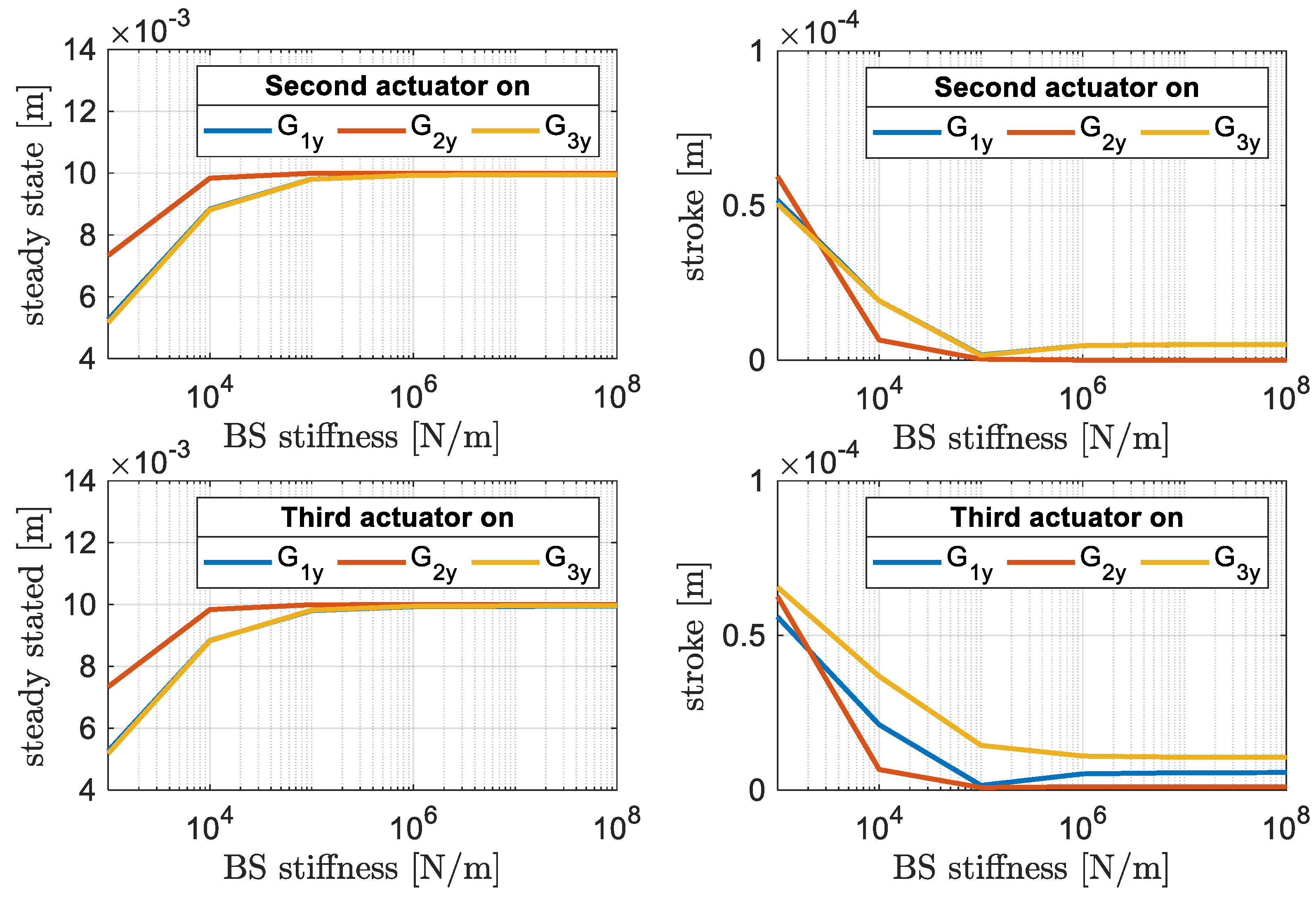
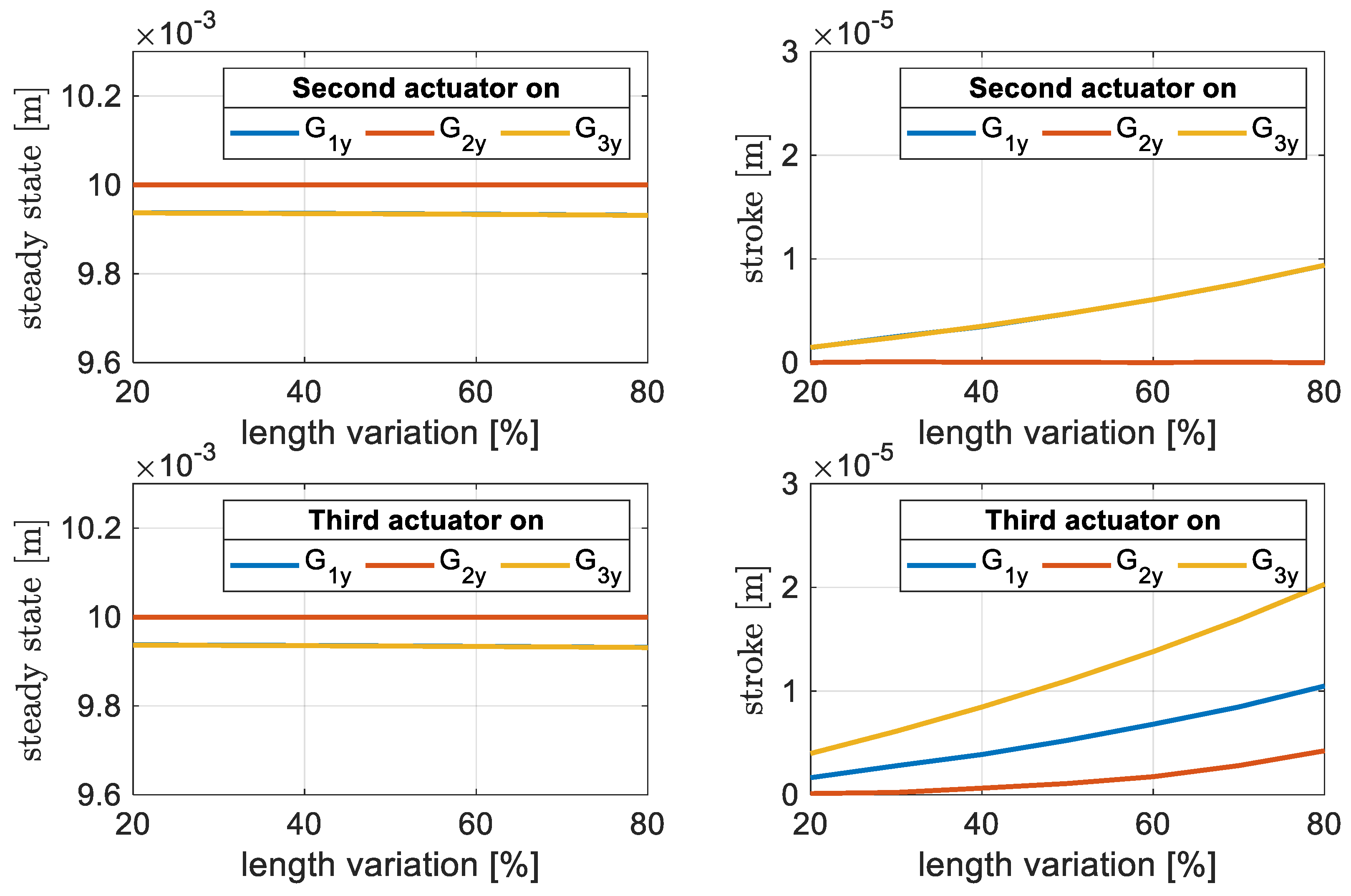
3. Results and Discussion

The simulation model, characterized in the previous section, is used to identify the relationship existing between the variation of the geometric parameters and the final configuration of the whole system considered. The simulations are conducted by considering the following nominal parameters values, chosen in order to reflect the typical behavior of DE systems:
  • d = 0.01 m;
  • w = −0.01 m;
  • ri, i ∈ {1, 2, 3} = 0.0025 m;
  • lDEi0, i ∈ {1, 2, 3} = 0.01 m;
  • lSi0, i ∈ {1, 2, 3} = 0.01 m;
  • mDEi, i ∈ {1, 2, 3} = 0.0118 g;
  • mSi, i ∈ {1, 2, 3} = 0.028 g;
  • mRFi, i ∈ {1, 2, 3} = 10 g;
  • kDEi, i ∈ {1, 2, 3} = 19.6 kN/m;
  • kSi, i ∈ {1, 2, 3} = 19.6 kN/m;
  • kBi, i ∈ {1, 2, 3} = 10 MN/m;
  • kFi, i ∈ {1, 2} = 0 N/m;
  • di0, i ∈ {1, 2, 3} = 0.02 m.
The DEA activation was simulated by reducing kDEi by a factor of 20%.
Simulations were conducted by keeping all parameters constant at nominal value and changing only one of them at each iteration, setting different values listed below:
  • α = [10−6, …, 106]: ratio between the stiffness of the elastic element placed in the center between two DE membranes (kF) and the silicone stiffness (ks);
  • kBi = [103, …, 108]: stiffness of the biasing system;
  • µ = [20%, …, 80%]: percentage variation of the DE length (lDEi0) relative to the sum of the DE and silicone lengths (3 lDEi0 + 3 lSi0) (this value will be kept as constant throughout the study).
These values were chosen in such a way to establish a useful sub-range, which shows how the steady-state values of the rigid frames’ vertical positions (i.e., G1y, G2y, G3y) undergo variations when the above listed parameters vary. Thus, it will be possible to understand which geometric value needs to input to obtain a desired output configuration.
The results are shown in Figure 3, Figure 4 and Figure 5, where the first and second lines show the output obtained by activating the second and third DEAs, respectively. The steady state value was computed as the corresponding equilibrium value of Giy, while the stroke was calculated as the absolute value of the corresponding variable before and after the actuation. In Figure 3, we can see that for high kFi values the stroke of nonactuated membranes is zero, while a coupling effect is observed for low kFi values. This indicates that the softer the central elastic element, the greater the influence that the actuation of one DEA has on the other two. Furthermore, it is interesting to note that for low kF values, we always found G2y (central DEA) values greater than both G1y and G3y (side DEAs). On the other hand, we observe the opposite situation if we only look at the stroke. This is due to the fact that, when the stiffness of the central element is too low, the second actuator will be very close to a singular configuration (i.e., a quasi-flat DEA membrane which prevents an in-plane Maxwell stress to be transmitted out-of-plane), causing a zero stroke during its actuation and a greater influence on the strokes of the neighbors.
Based on these considerations, we decided to continue the study of the remaining parameters considering the absence of the central element (i.e., kFi = 0). In this way, we aimed at emphasizing the mutual dependencies among neighbor actuators. In fact, by extending the explanation of the singular configuration also to these studies, it is evident that the effect of the actuation of the second DEA was more strongly affected than the remaining ones (Figure 4). Furthermore, it can be seen that increasing the stiffness of the biasing system leads to larger steady-state values, but at the same time to a zero stroke (thus making this phase not meaningful).
Finally, in Figure 5 it can be seen that as the relative amount of DE increases, the stroke increases as well. This is expected, since the greater the portion of the membrane softened induced by the applied voltage, the greater the expected stroke.

4. Conclusions

In this work, we have presented a physics-based model of an array of DEA elements. To deal with the high dimensionality of the system (i.e., 25 independent degrees of freedom), the constitutive equations were obtained via an energetic approach, which allows for a systematic and modular description of the many parts which make up the system. The developed model is useful to accurately understand how the system parameters (i.e., geometry, bias force) affect the mutual electro-mechanical coupling among the many DEA taxels during actuation.
The provided investigation showed that the softer the connection between DEA taxels and rigid frame, the higher the influences between the actuators. Thanks to this study, it will be possible to identify the optimal geometric combination of values that allow the stroke to be reached and a desired configuration, without neglecting the electro-mechanical coupling effects that an actuator has on its neighbors. In addition, it was observed that softer biasing springs and wider DE/passive silicone ratios have an overall positive effect of the actuation stroke. The obtained results can then be used to guide the design and manufacturing of future DEA array systems.
In future research, the developed model will be expanded with dynamic effects describing system inertia and DE viscoelasticity. In addition, more accurate nonlinear models will be adopted for describing both DE and silicone membranes, as well as more advanced types of biasing elements (i.e., bistable ones). Experimental validation of the full model will then be conducted. The validated model will then be used the design optimization, scaling, and control of cooperative DEA systems.

Author Contributions

S.C. performed the simulations and wrote the paper. All authors have read and agreed to the published version of the manuscript.

Acknowledgments

The author gratefully acknowledges the support of the Deutsche Forschungsgemeinschaft (DFG, German Research Foundation) through Priority Program SPP 2206 “Cooperative Multistage Multistable Microactuator Systems” (Projects: RI3030/2-1, SCHU1609/7-1, SE704/9-1).

Conflicts of Interest

The author declares no conflict of interest. The founding sponsors had no role in the design of the study; in the collection, analyses, or interpretation of data; in the writing of the manuscript, and in the decision to publish the results.

Abbreviations

DEDielectric Elastomer
DEADielectric Elastomer Actuators

References

  1. Carpi, F.; Rossi, D.D.; Kornbluh, R.; Pelrine, R.E.; Sommer-Larsen, P. Dielectric Elastomers as Electromechanical Transducers: Fundamentals, Materials, Devices, Models and Applications of an Emerging Electroactive Polymer Technology; Elsevier: Amsterdam, The Netherlands, 2011. [Google Scholar]
  2. Hill, M.; Rizzello, G.; Seelecke, S. Development and experimental characterization of a pneumatic valve actuated by a dielectric elastomer membrane. Smart Mater. Struct. 2017, 26, 085023. [Google Scholar] [CrossRef]
  3. Giousouf, M.; Kovacs, G. Dielectric elastomer actuators used for pneumatic valve technology. Smart Mater. Struct. 2013, 22, 104010. [Google Scholar] [CrossRef]
  4. Ghazali, F.A.M.; Mah, C.K.; AbuZaiter, A.; Chee, P.S.; Ali, M.S.M. Soft dielectric elastomer actuator micropump. Sens. Actuators A Phys. 2017, 263, 276–284. [Google Scholar] [CrossRef]
  5. Loverich, J.J.; Kanno, I.; Kotera, H. Concepts for a new class of all-polymer micropumps. Lab Chip 2006, 6, 1147–1154. [Google Scholar] [CrossRef] [PubMed]
  6. Heydt, R.; Kornbluh, R.; Eckerle, J.; Pelrine, R. Sound radiation properties of dielectric elastomer electroactive polymer loudspeakers. In Proceedings of the Smart Structures and Materials 2006: Electroactive Polymer Actuators and Devices (EAPAD), San Diego, CA, USA, 22 March 2006; Volume 6168, p. 61681M. [Google Scholar]
  7. Heydt, R.; Pelrine, R.; Joseph, J.; Eckerle, J.; Kornbluh, R. Acoustical performance of an electrostrictive polymer film loudspeaker. J. Acoust. Soc. Am. 2000, 107, 833–839. [Google Scholar] [CrossRef] [PubMed]
  8. Conn, A.T.; Hinitt, A.D.; Wang, P. Soft segmented inchworm robot with dielectric elastomer muscles. In Proceedings of the Electroactive Polymer Actuators and Devices (EAPAD), San Diego, CA, USA, 8 March 2014; p. 90562L. [Google Scholar]
  9. Shintake, J.; Rosset, S.; Schubert, B.; Floreano, D.; Shea, H.R. Versatile Soft Grippers with Intrinsic Electroadhesion Based on Multifunctional Polymer Actuators. Adv. Mater. 2016, 28, 231–238. [Google Scholar] [CrossRef]
  10. Prechtl, J.; Kunze, J.; Nalbach, S.; Seelecke, S.; Rizzello, G. Soft robotic module actuated by silicone-based rolled dielectric elastomer actuators: Modeling and simulation. In Proceedings of the Electroactive Polymer Actuators and Devices (EAPAD), online only, 22 April 2020. [Google Scholar] [CrossRef]
  11. Maffli, L.; Rosset, S.; Shea, H.R. Mm-size bistable zipping dielectric elastomer actuators for integrated microfluidics. In Proceedings of the Electroactive Polymer Actuators and Devices (EAPAD), San Diego, CA, USA, 9 April 2013; p. 86872M. [Google Scholar]
  12. Chakraborti, P.; Toprakci, H.A.K.; Yang, P.; Di Spigna, N.; Franzon, P.; Ghosh, T. A compact dielectric elastomer tubular actuator for refreshable Braille displays. Sens. Actuators A Phys. 2012, 179, 151–157. [Google Scholar] [CrossRef]
  13. Carpi, F.; Frediani, G.; De Rossi, D. Electroactive elastomeric haptic displays of organ motility and tissue compliance for medical training and surgical force feedback. IEEE Trans. Biomed. Eng. 2009, 56, 2327–2330. [Google Scholar] [CrossRef]
  14. Kovacs, G. Arm Wrestling Robot Driven by Dielectric Elastomer Actuators. In Proceedings of the First IEEE/RAS-EMBS nternational Conference on Biomedical Robotics and Biomechatronics, Pisa, Italy, 20–22 February 2006; pp. 260–265. [Google Scholar]
  15. Aksoy, B.; Shea, H. Reconfigurable and Latchable Shape-Morphing Dielectric Elastomers Based on Local Stiffness Modulation. Adv. Funct. Mater. 2020, 200159710. [Google Scholar] [CrossRef]
Figure 1. Top view of the dielectric elastomer actuator (DEA) array. The dashed line represents the transversal plane on which the model is based.
Proceedings 64 00028 g001
Figure 2. 2-D cross-sectional view of DEA array: (a) undeformed configuration; (b) configuration after horizontal prestretch; (c) configuration after adding biasing systems; (d) configuration after electrical activation of the second DEA.
Proceedings 64 00028 g002
Figure 3. Steady values of G1y, G2y, G3y, (left-hand side) and corresponding vertical actuation stroke (right-hand side), achieved by varying the ratio between the stiffness of the frame element kFi and the stiffness of the silicone kSi.
Proceedings 64 00028 g003
Figure 4. Steady values of G1y, G2y, G3y, (left-hand side) and corresponding vertical actuation stroke (right-hand side), achieved by varying the biasing system stiffness kBi.
Proceedings 64 00028 g004
Figure 5. Steady values of G1y, G2y, G3y, (left-hand side) and corresponding vertical actuation stroke (right-hand side), achieved by varying the DE membrane’s external radius.
Proceedings 64 00028 g005
Publisher’s Note: MDPI stays neutral with regard to jurisdictional claims in published maps and institutional affiliations.

