Reliable Long-Range Multi-Link Communication for Unmanned Search and Rescue Aircraft Systems in Beyond Visual Line of Sight Operation


Abstract
:1. Introduction
 accompanied one large-scale rescue simulation of the German Maritime Search and Rescue Association (German: “Deutsche Gesellschaft zur Rettung Schiffbrüchiger”, DGzRS). During those flights, real video payload was transferred between UAS and the local ground control and also used for the control of the UAS. In the second experiment series, the maximum performance of the communication was investigated. In order not to influence the video stream and flight control, a manned flight was conducted.
2. Related Work
3. Proposed System Design, Architecture and Implementation
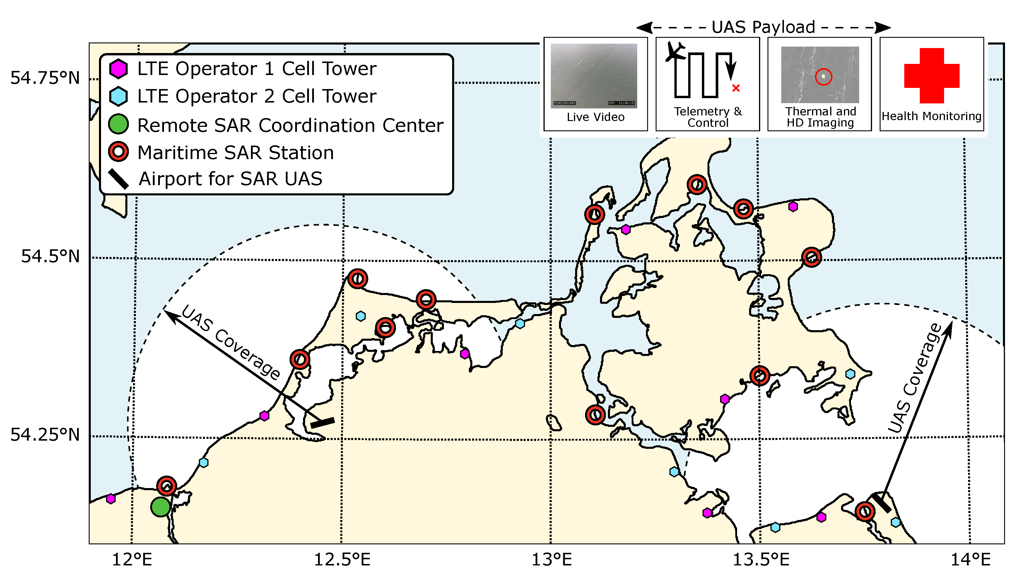
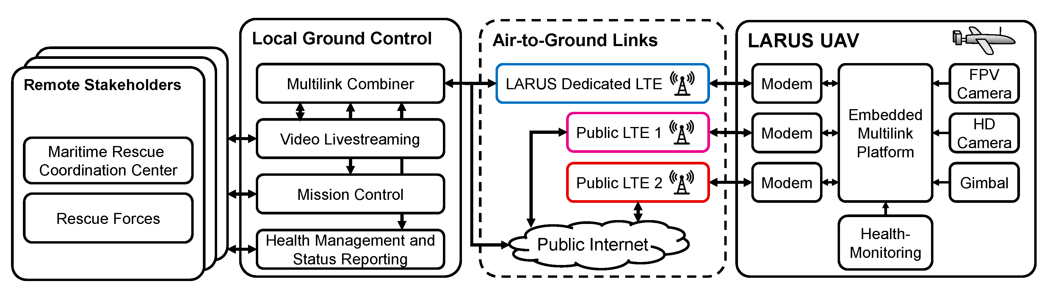
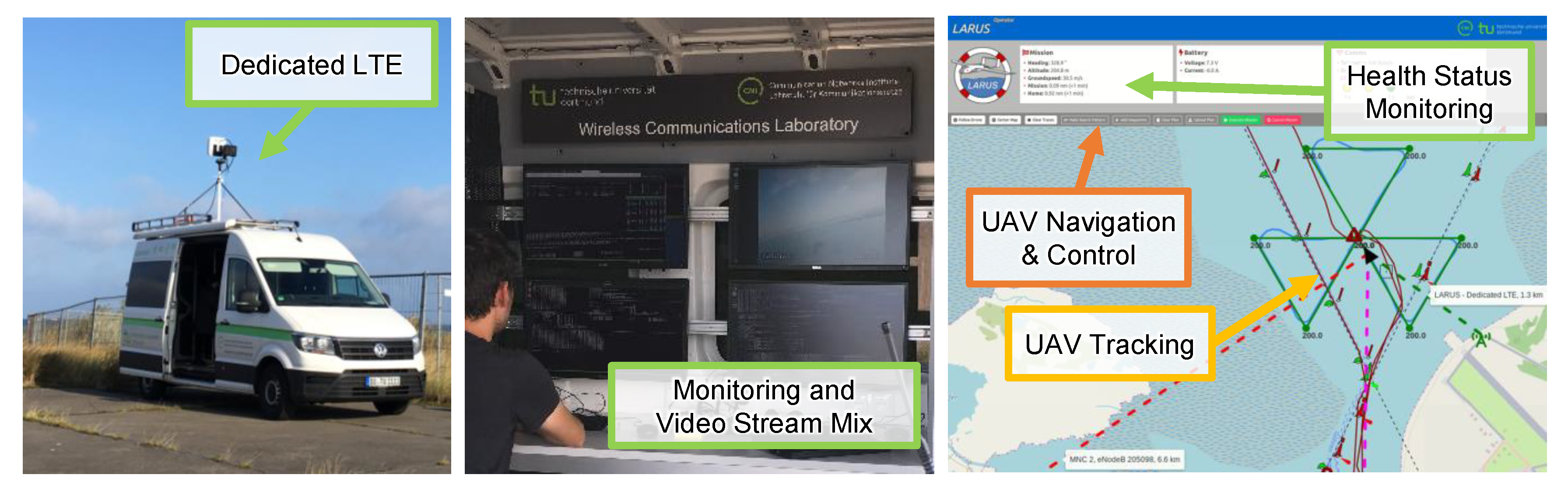
 . All data is made available to external stakeholders via a unified live video stream, for example, during Peenemünde flight experiment (Final Demonstrator) rescue forces on a boat set out to save persons out of the water, were able to see live images provided by the plane’s cameras. In addition, the MRCC, which was located several hundred kilometers away, was able to interact with the mission control.
4. Validation Scenarios and Published Datasets
 to
to  as defined in the table. In addition, Figure 7 shows a map and the trajectories of all flights. is a medium ranged flight with a maximum distance of 15 km above the island Greifswalder Oie. The focus of this flight was on hardware evaluation tests, therefore only a single-link communication was conducted. Data set consists of two parts: In the first part
  , a long-range distance flight in North–West direction was conducted, targeting the island Rügen. The altitude during the long-range flight was 400 m and the maximum distance between UAS and ground station was approx. 21 km. The flight tests accompanied a SAR exercise of the German maritime rescue forces. Therefore, in the following part
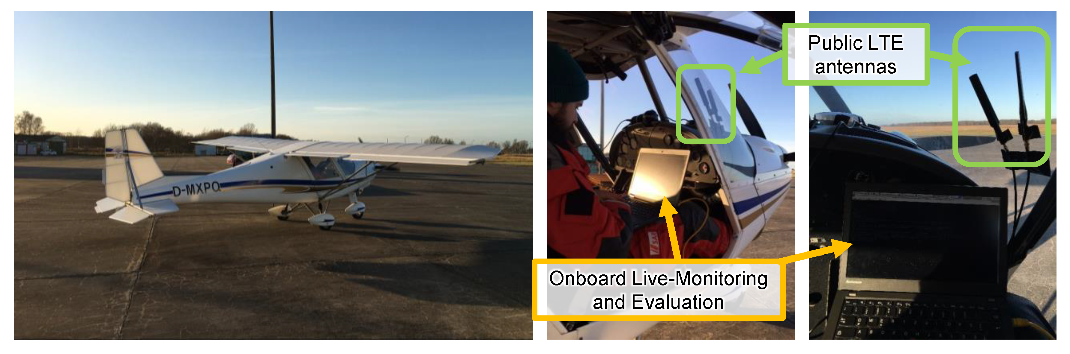
  , the drone performed a Creeping Line search pattern exploring a rectangular area below the plane. Both datasets implement full multi-link communication. The chronologically following data set contains measurements in the area around Peenemünde airport. A whole SAR scenario was conducted as part of the final project presentation of the LARUS project. Here, the UAS searched along the shore for a missing ship with a person floating on the open water. Having found the ship the UAS performed a Sector Search pattern, which is recognizable by the triangular-shaped trajectories. In the previous scenarios, the UAS communication links were used to transport and deliver mandatory telemetry, video imaging, and mission-related information. Therefore, the communication link’s limits could not be assessed without endangering and influencing the flight and mission performance. To complement and round off previous measurements, one manned validation experiment was carried out using a lightweight plane
  . Here, the communication link’s maximum throughput was quantified as well as network availability and roaming behavior in the proximity of the Polish–German border.
5. Analysis of Public LTE Networks in Maritime Airspace
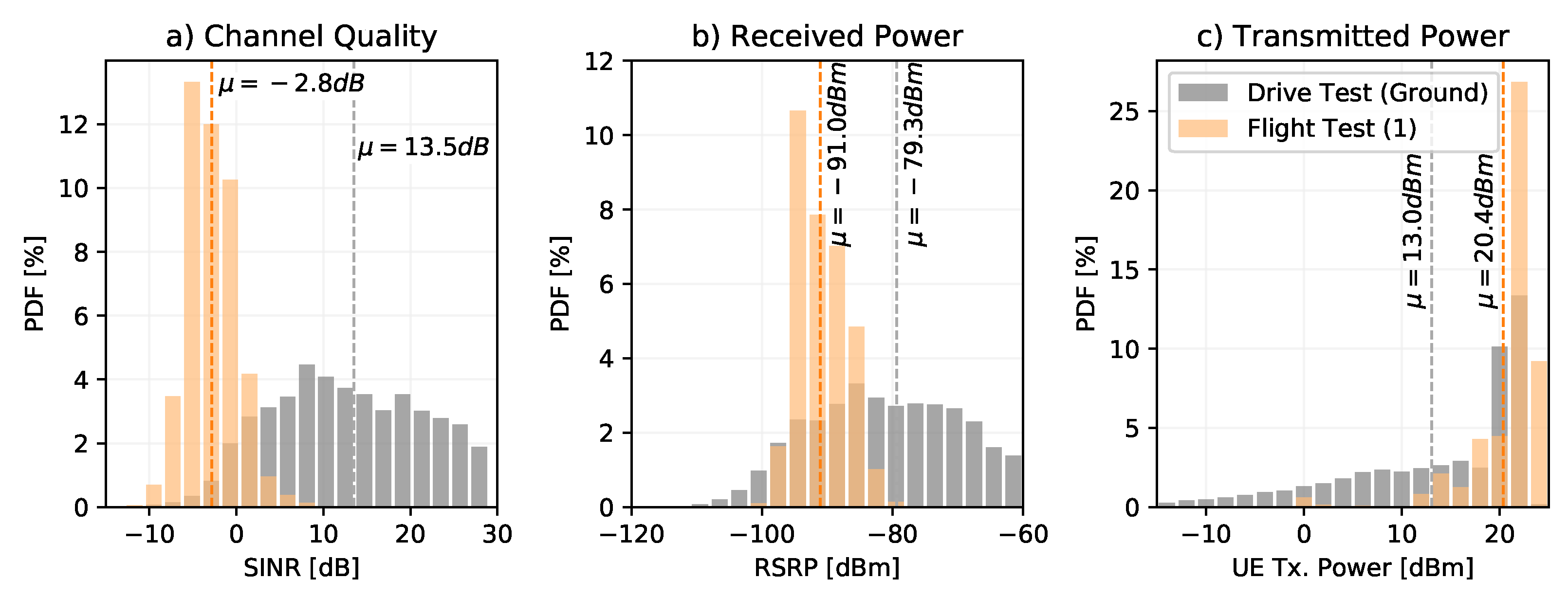
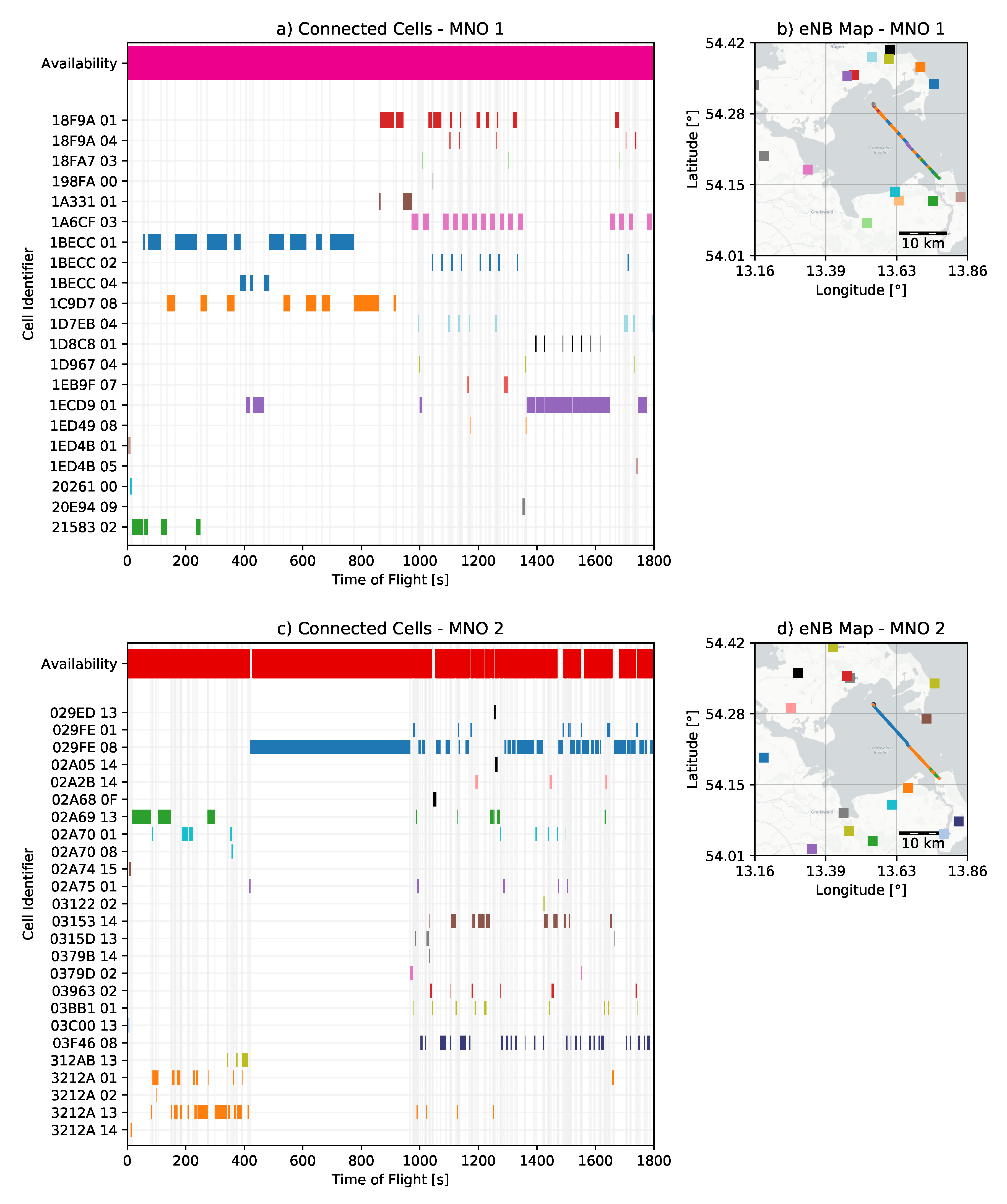
to a ground reference measurement. For channel quality, the UE-estimated Signal-to-Interference-plus-Noise Ratio (SINR) is analyzed. The received power is presented in form of the Reference Signal Received Power (RSRP). An estimate of the UE’s power consumption is provided by the Transmission Power. The ground reference measurement was recorded during a drive test in a car on a German highway. The reference measurement uses the same LTE modem, antennas, and MNOs that were used in the aerial measurement campaign. The resulting figure shows the value distribution of each indicator incorporated by the Probability Density Function (PDF). For the aerial test, the SINR ranges from to 5 dB with an average of dB. The ground test results in a value range from −5 to 25 dB and a mean value of 13.5 dB. Besides the fact that aerial values are dB below ground average, SINR values below 0 dB indicate the worst channel conditions. Communication needs to make use of the most robust modulation and coding schemes to successfully transmit data. Additionally, LTE’s Hybrid Automatic Repeat Request (HARQ), which can recover packets that have not been successfully transmitted, supports the communication link. However, this results in a lower data rate and higher latency. If bad channel conditions cannot be fully compensated, side-effects will occur, from sporadic packet losses up to the whole communication link becoming unavailable. The poor channel quality is also recognizable in the received power. With a difference of dB, the average aerial RSRP is significantly below the ground-based one. The difference is lower in comparison to the SINR because that the RSRP does include only the usable signal and no interference power levels. The UE uses more energy for aerial communications in terms of energy efficiency. The aerial data was transferred using an average of 20.4 dBm transmit power, whereas the ground reference transmitted on average 13.0 dBm, which is 7.4 dB less. Due to the limited resource availability in UAVs, the more than fivefold increased energy consumption must be taken into account when dimensioning power supplies.. The first column (subplots a,c) indicates the cell identifier to which the LTE modem of the UAV is currently connected to. The first five characters of the Cell ID represent the identifier of the eNB, the last two characters indicate different sectors or antennas of the same eNB. Within all figures, different antennas were grouped for each eNB and share the same colors. The upper row of the cell identifier plot shows the availability of the MNO. The availability represents whether the network was able to transport payload data. The detailed methodology for the determination of the availability will be discussed in detail in the subsequent section and Figure 13. Within Figure 12, the right column (b,d) shows a map of the locations of each eNB. The upper row (a,b) represents MNO 1 evaluations and the lower row (c,d) MNO 2 evaluations. During the first half hour of the flight, the UAV is connected to 21 different eNBs of MNO 1 and 25 eNBs of MNO 2. Throughout the flight, the UAV’s LTE modem performs 111 handovers between cells of those eNBs, which correspond to an average length of stay of 16.2 s per cell for MNO 1. For MNO 2, 166 cell changes were conducted leading to an even smaller duration of stay of 10.8 s. Handovers in LTE are either initiated by the or by the UE. However, the final handover decision remains at the core network and aims at maintaining and maximizing the user’s Quality of Service (QoS) (c.f. also resource allocation in next-generation broadband wireless access networks [55]). Here, it is once again obvious that the decisions are optimized for ground users: handovers are conducted between unsuitable cells, which leads to a back-and-forth switching between two cells. This effect can be seen, e.g., at MNO 1 between cells 1ECD901 (purple) and 1D8C801 (black) (at time of flight 1300 s–1700 s) or between cells 1A6CF03 (pink), 1BECC02 (blue), and 18F9A01 (red) (1000 s–1300 s). Typically, the decision policies use the UE’s measurement report, which indicates the quality of all cells the UE can see. In the underlying scenario, typically all cells have unfavorable channel conditions. For future work, we propose a mobility and maritime channel aware handover decision policy for UAVs. Hereby, handover decisions could be improved significantly. An additional optimization would be to disable frequency bands above 1 GHz. On a few occasions, the UEs were able to detect cells in LTE band 1 (2100 MHz) and band 7 (2600 MHz). Those cells typically have more bandwidth and most MNO aim at moving users there for improved load balancing. In the underlying maritime scenario, those handovers failed on a regular basis.6. Evaluation of Multi-Link Empowered Link Availability Improvement
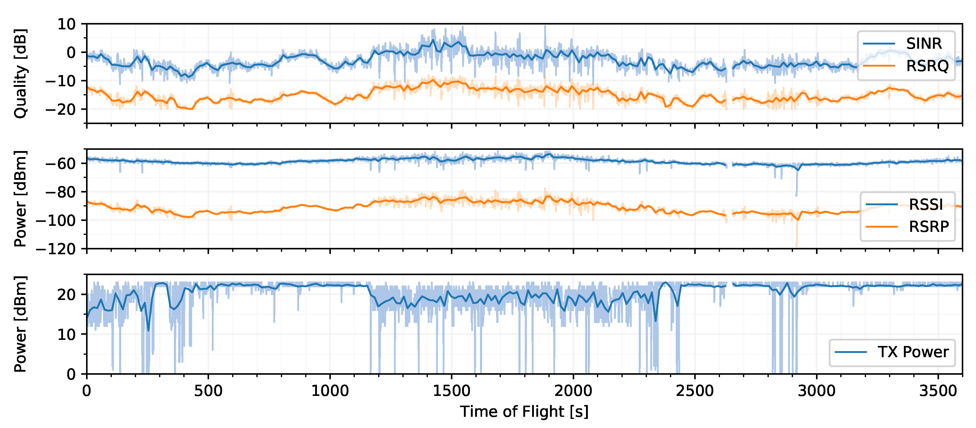
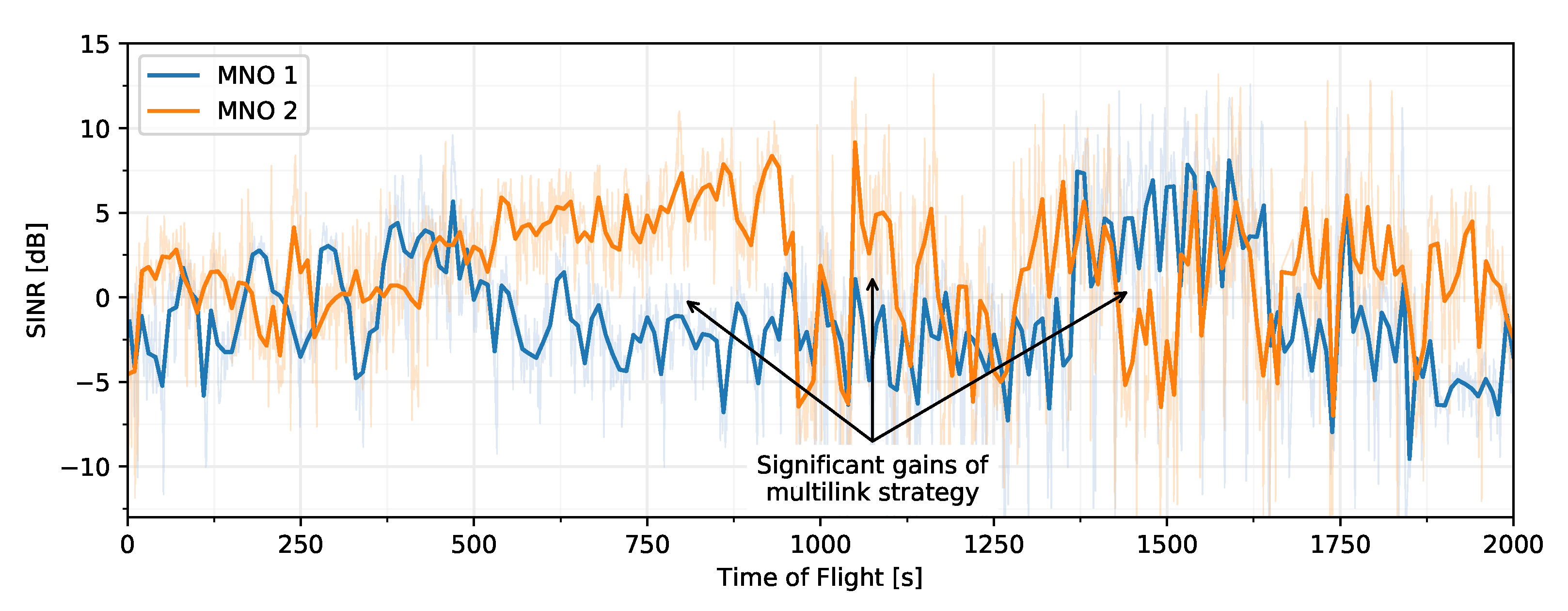
and Ribnitz-Damgarten are analyzed and evaluated. Therefore, after discussing the benefits of link quality improvement due to the multi-link architecture, the subsequent passage first describes availability calculation methodology and afterwards evaluates and discusses multi-link empowered link availability gains.. The figure shows a time series of the SINR signal quality over time for both MNOs. Raw samples are plotted in the background, the bold lines show a post-processed moving average of 10 s. As discussed previously, SINR values below 0 dB indicate the worst channel conditions. However, the plot shows that most of the time when one MNO suffers from bad channel quality, the other operator is able to assist. This effect can be seen for a long duration of several minutes, e.g., during a time of flight between 500 s and 900 s. In general, one can say that the more heterogeneous the links are, the more gain the multi-link approach yields. . The multi-link approach yields the highest availability in all scenarios. For Peenemünde SAR Mission, 99.8% availability was achieved, which is primarily because the mission was flown in the proximity of the shore, where MNO 1 had a good single link performance of 97.7%. Nevertheless, in the Peenemünde long-range scenario, the multi-link performed very well with a similar score of 98.2%. Here, the single link availability of 90.8% of MNO 1 was lower than in the previous flight. In the Ribnitz-Damgarten scenario, both MNO’s single link performances were significantly lower than in the Peenemünde scenarios. This is due to the fact that the Ribnitz-Damgarten site is more rural and less populated and contains fewer surrounding LTE coverage. Nevertheless, the multi-link approach results in the highest availability of 89.3%, which is an increase of 20% for MNO 1 and 17% for MNO 2. In conclusion, it can be stated that the multi-link approach increases the availability in all scenarios.7. Overall Application Layer Performance Evaluation
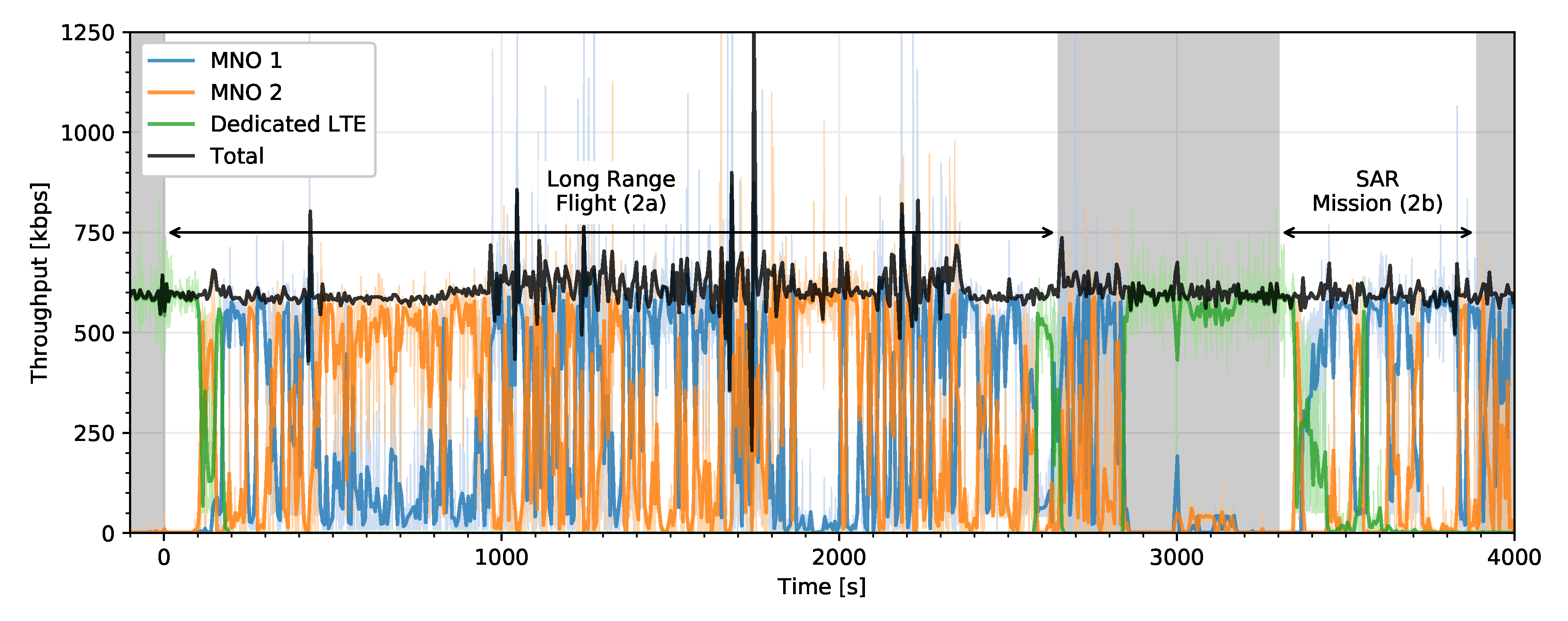
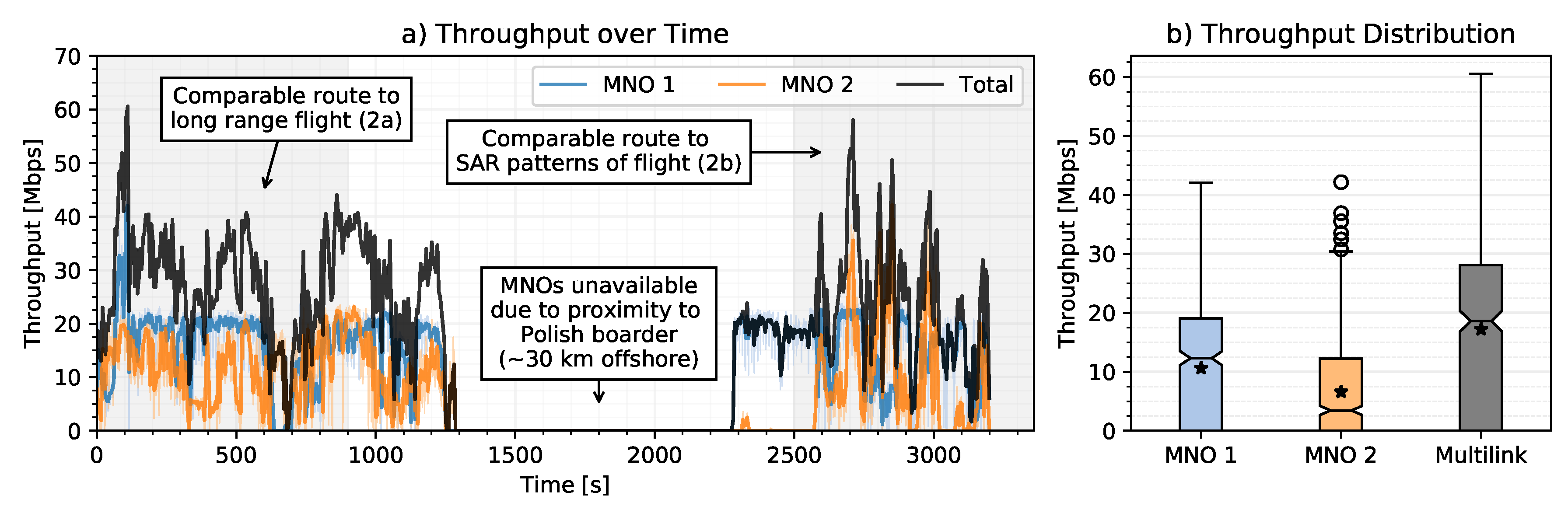
. The throughput was recorded at the UAV using the open source software Bandwidth Monitor NG (bwm-ng), which captures the data rates for each interface. Throughout the experiment, the MPTCP scheduler “Lowest Round-Trip-Time First (LRF)” was used. The plot shows the data rates for the public MNOs 1 and 2 as well as for a local dedicated LTE network and the total payload data rate. The bold lines represent a rolling mean of 5 s of the raw samples (thin lines). The dedicated LTE is a small cell solution located at the airport to allow easy maintenance when the UAV is at the airport, where public MNO coverage is not always available—especially in shadowing of buildings. Due to the transparent nature of MPTCP, in the future, this LTE small cell can be replaced by a full long-range LTE solution, which could assist as a third aerial data link. During the experiments, a video stream with an approximate data rate of 500 kbps as well as telemetry and control messages with approx. 100 kbps (including the previously described ICMP packets) were transmitted. The plot illustrates the smooth handover between the data links, which is enabled by MPTCP. When one link is unavailable, data is outsourced on the other link.) the communication links were not maxed out to avoid interferences on the video stream and telemetry and control data flows. In order to assess maximum throughput performance, a manned flight was conducted (dataset ). Figure 18 presents the evaluation of the experiment. The left subplot (a) illustrates the throughput over each individual link as well as the sum of all links. Subplot (b) shows the statistical boxplot evaluation. To evaluate maximum performance, an iPerf-like set-up was used: over a TCP socket randomly generated data was sent. Whenever sending was possible the data was sent over the socket. The outgoing buffer was always filled. Again, the bwm-ng tool was used to record the throughput for each interface. During the experiment, no useful payload (e.g., video stream or telemetry and control data) was transmitted, which is contrary to the previous experiments. MNO 1 achieved with 10.6 Mbps a higher throughput than MNO 2 with 6.6 Mbps during the experiments. The peak data rate was 42 Mbps for the single links, being the rare exception right at the beginning of the flight. The theoretic maximum achievable throughput in LTE uplink with the underlying hardware is at 50 Mbps. The first part of this manned flight is comparable to the route of Peenemünde long-range flight . Afterwards, the network performance in direction to the Polish border has been evaluated, where network coverage of the German MNOs was not always given. As the antennas were mounted in flight direction, improved performance is assumed with an optimized antenna positioning. On the way back, when approaching Peenemünde airport, the MNO 2 LTE modem tried to attach to a Polish MNO several times. However, the roaming attempts were unsuccessful. MNO 1 recovered and maintained a good throughput of ~20 Mbps. Despite being in MNO 2 network coverage, the LTE modem of MNO 2 was unable to directly reattach to the network and pick up service. The flight was completed performing SAR search patterns similar to Peenmünde flight .8. Conclusions
Author Contributions
Funding
Acknowledgments
Conflicts of Interest
Abbreviations
| ADMIT | quAlity-Driven MultIpath TCP |
| BVLOS | Beyond Visual Line of Sight |
| Cell ID | Cell Identifier |
| DASH | Dynamic Adaptive Streaming over HTTP |
| EIRP | Effective Isotropic Radiated Power |
| eNB | enhanced NodeB |
| FPV | First-Person View |
| GUI | Graphical User Interface |
| HARQ | Hybrid Automatic Repeat Request |
| HD | High Definition |
| HTTP | Hypertext Transfer Protocol |
| ICAO | International Civil Aviation Organization |
| ICMP | Internet Control Message Protocol |
| LOS | Line of Sight |
| LTE | Long Term Evolution |
| MCTCP | Multi-Connection TCP |
| MMTCP | Maximum Multipath TCP |
| MNO | Mobile Network Operator |
| MPQUIC | Multipath QUIC |
| MPTCP | Multipath TCP |
| MPUDP | Multipath UDP |
| MRCC | Maritime Rescue and Control Center |
| NASA | National Aeronautics and Space Administration |
| NLOS | Non-Line of Sight |
| Probability Density Function | |
| QoS | Quality of Service |
| QUIC | Quick UDP Internet Connections |
| RSRP | Reference Signal Received Power |
| RSRQ | Reference Signal Received Quality |
| RSSI | Received Signal Strength Indicator |
| RTMP | Real-Time Messaging Protocol |
| RTT | Round Trip Time |
| SAR | Search and Rescue |
| SCTP | Stream Control Transmission Protocol |
| SINR | Signal-to-Interference-plus-Noise Ratio |
| TCP | Transmission Control Protocol |
| UAS | Unmanned Aircraft System |
| UAV | Unmanned Aerial Vehicle |
| UDP | User Datagram Protocol |
| UE | User Equipment |
| VPN | Virtual Private Network |
| WLAN | Wireless Local Area Network |
References
- LARUS Research Project Website. 2019. Available online: http://larus.kn.e-technik.tu-dortmund.de (accessed on 21 January 2020).
- Video of the LARUS Project. 2020. Available online: https://www.youtube.com/watch?v=kJ9ABk8Rr4M (accessed on 10 March 2020).
- Shakhatreh, H.; Sawalmeh, A.H.; Al-Fuqaha, A.; Dou, Z.; Almaita, E.; Khalil, I.; Othman, N.S.; Khreishah, A.; Guizani, M. Unmanned Aerial Vehicles (UAVs): A Survey on Civil Applications and Key Research Challenges. IEEE Access 2019, 7, 48572–48634. [Google Scholar] [CrossRef]
- Cubber, G.D.; Doroftei, D.; Rudin, K.; Berns, K.; Matos, A.; Serrano, D.; Sanchez, J.; Govindaraj, S.; Bedkowski, J.; Roda, R.; et al. Introduction to the Use of Robotic Tools for Search and Rescue. In Search and Rescue Robotics; IntechOpen: London, UK, 2017; Chapter 1. [Google Scholar] [CrossRef] [Green Version]
- Lygouras, E.; Santavas, N.; Taitzoglou, A.; Tarchanidis, K.; Mitropoulos, A.; Gasteratos, A. Unsupervised Human Detection with an Embedded Vision System on a Fully Autonomous UAV for Search and Rescue Operations. Sensors 2019, 19, 3542. [Google Scholar] [CrossRef] [PubMed] [Green Version]
- Seguin, C.; Blaquière, G.; Loundou, A.; Michelet, P.; Markarian, T. Unmanned aerial vehicles (drones) to prevent drowning. Resuscitation 2018, 127, 63–67. [Google Scholar] [CrossRef] [PubMed]
- Półka, M.; Ptak, S.; Kuziora, Ł.; Kuczyńska, A. The Use of Unmanned Aerial Vehicles by Urban Search and Rescue Groups. In Drones; Dekoulis, G., Ed.; IntechOpen: London, UK, 2018; Chapter 6. [Google Scholar] [CrossRef] [Green Version]
- Roberts, J.; Frousheger, D.; Williams, B.; Campbell, D.; Walker, R. How the Outback Challenge Was Won: The Motivation for the UAV Challenge Outback Rescue, the Competition Mission, and a Summary of the Six Events. IEEE Robot. Autom. Mag. 2016, 23, 54–62. [Google Scholar] [CrossRef]
- Marques, M.M.; Dias, P.; Santos, N.P.; Lobo, V.; Batista, R.; Salgueiro, D.; Aguiar, A.; Costa, M.; da Silva, J.E.; Ferreira, A.S.; et al. Unmanned aircraft systems in maritime operations: Challenges addressed in the scope of the SEAGULL project. In Proceedings of the OCEANS 2015—Genova, Genoa, Italy, 18–21 May 2015; pp. 1–6. [Google Scholar] [CrossRef]
- Volkert, A.; Hackbarth, H.; Lieb, T.J.; Kern, S. Flight Tests of Ranges and Latencies of a Threefold Redundant C2 Multi-Link Solution for Small Drones in VLL Airspace. In Proceedings of the 2019 Integrated Communications, Navigation and Surveillance Conference (ICNS), Herndon, VA, USA, 9–11 April 2019; pp. 1–14. [Google Scholar] [CrossRef] [Green Version]
- Fragkos, G.; Tsiropoulou, E.E.; Papavassiliou, S. Disaster Management and Information Transmission Decision-Making in Public Safety Systems. In Proceedings of the 2019 IEEE Global Communications Conference (GLOBECOM), Waikoloa Village, HI, USA, 9–13 December 2019; pp. 1–6. [Google Scholar]
- Ponchak, D.S.; Templin, F.L.; Sheffield, G.; Taboso, P.; Jain, R. Reliable and secure surveillance, communications and navigation (RSCAN) for Unmanned Air Systems (UAS) in controlled airspace. In Proceedings of the 2018 IEEE Aerospace Conference, Big Sky, MT, USA, 3–10 March 2018; pp. 1–14. [Google Scholar] [CrossRef] [Green Version]
- Apaza, R.D.; Popescu, L. The way to the future has already started: ICAO Aeronautical Telecommunication Network (ATN) using Internet Protocol Suite (IPS) Standards and Protocol evolution update. In Proceedings of the 2018 IEEE/AIAA 37th Digital Avionics Systems Conference (DASC), London, UK, 23–27 September 2018; pp. 1–6. [Google Scholar] [CrossRef] [Green Version]
- Azari, M.M.; Rosas, F.; Pollin, S. Cellular Connectivity for UAVs: Network Modeling, Performance Analysis, and Design Guidelines. IEEE Trans. Wirel. Commun. 2019, 18, 3366–3381. [Google Scholar] [CrossRef] [Green Version]
- Raiciu, C.; Paasch, C.; Barre, S.; Ford, A.; Honda, M.; Duchene, F.; Bonaventure, O.; Handley, M. How Hard Can It Be? Designing and Implementing a Deployable Multipath TCP. In Proceedings of the 9th USENIX Symposium on Networked Systems Design and Implementation (NSDI 12), San Jose, CA, USA, 25–27 April 2012; pp. 399–412. [Google Scholar]
- Jagetiya, A.; Rama Krishna, C.; Haider, Y. Survey of Transport Layer Multihoming Protocols and Performance Analysis of MPTCP. In Proceedings of the 2nd International Conference on Communication, Computing and Networking, Chandigarh, India, 29–30 March 2018; Krishna, C.R., Dutta, M., Kumar, R., Eds.; Springer: Singapore, 2019; pp. 15–24. [Google Scholar]
- Ye, G.; Saadawi, T.N.; Lee, M. IPCC-SCTP: An enhancement to the standard SCTP to support multi-homing efficiently. In Proceedings of the IEEE International Conference on Performance, Computing, and Communications, Phoenix, AZ, USA, 15–17 April 2004; pp. 523–530. [Google Scholar] [CrossRef]
- Abrahamsson, H.; Abdesslem, F.B.; Ahlgren, B.; Brunstrom, A.; Marsh, I.; Björkman, M. Connected Vehicles in Cellular Networks: Multi-Access Versus Single-Access Performance. In Proceedings of the 2018 Network Traffic Measurement and Analysis Conference (TMA), Vienna, Austria, 26–29 June 2018; pp. 1–6. [Google Scholar] [CrossRef]
- Scharf, M.; Banniza, T. MCTCP: A Multipath Transport Shim Layer. In Proceedings of the 2011 IEEE Global Telecommunications Conference—GLOBECOM 2011, Houston, TX, USA, 5–9 December 2011; pp. 1–5. [Google Scholar] [CrossRef]
- Hesmans, B.; Duchene, F.; Paasch, C.; Detal, G.; Bonaventure, O. Are TCP Extensions Middlebox-Proof? In Proceedings of the 2013 Workshop on Hot Topics in Middleboxes and Network Function Virtualization, HotMiddlebox ’13, Santa Barbara, CA, USA, 9 December 2013; Association for Computing Machinery: New York, NY, USA, 2013; pp. 37–42. [Google Scholar] [CrossRef] [Green Version]
- Khalili, R.; Gast, N.; Popovic, M.; Le Boudec, J.Y. MPTCP is Not Pareto-Optimal: Performance Issues and a Possible Solution. IEEE/ACM Trans. Netw. 2013, 21, 1651–1665. [Google Scholar] [CrossRef] [Green Version]
- Kheirkhah, M.; Wakeman, I.; Parisis, G. MMPTCP: A multipath transport protocol for data centers. In Proceedings of the IEEE INFOCOM 2016—The 35th Annual IEEE International Conference on Computer Communications, San Francisco, CA, USA, 10–15 April 2016; pp. 1–9. [Google Scholar] [CrossRef] [Green Version]
- Lukaszewski, D.; Xie, G. Multipath Transport for Virtual Private Networks. In Proceedings of the 10th USENIX Workshop on Cyber Security Experimentation and Test (CSET 17), USENIX Association, Vancouver, BC, Canada, 14 August 2017. [Google Scholar]
- Behnke, D.; Priebe, M.; Rohde, S.; Heimann, K.; Wietfeld, C. ScalaNC—Scalable heterogeneous link aggregation enabled by Network Coding. In Proceedings of the 13th IEEE International Conference on Wireless and Mobile Computing, Networking and Communications (WiMob 2017)—Fourth International Workshop on Emergency Networks for Public Protection and Disaster Relief (EN4PPDR’17), Rome, Italy, 9–11 October 2017. [Google Scholar]
- Cloud, J.; du Pin Calmon, F.; Zeng, W.; Pau, G.; Zeger, L.M.; Medard, M. Multi-Path TCP with Network Coding for Mobile Devices in Heterogeneous Networks. In Proceedings of the 2013 IEEE 78th Vehicular Technology Conference (VTC Fall), Las Vegas, NV, USA, 2–5 September 2013; pp. 1–5. [Google Scholar] [CrossRef] [Green Version]
- Wu, J.; Yuen, C.; Cheng, B.; Wang, M.; Chen, J. Streaming High-Quality Mobile Video with Multipath TCP in Heterogeneous Wireless Networks. IEEE Trans. Mobile Comput. 2016, 15, 2345–2361. [Google Scholar] [CrossRef]
- Hayes, B.; Chang, Y.; Riley, G. Adaptive bitrate video delivery using HTTP/2 over MPTCP architecture. In Proceedings of the 2017 13th International Wireless Communications and Mobile Computing Conference (IWCMC), Valencia, Spain, 26–30 June 2017; pp. 68–73. [Google Scholar] [CrossRef]
- Jung, W.S.; Yim, J.; Ko, Y.B. Adaptive offloading with MPTCP for unmanned aerial vehicle surveillance system. Ann. Telecommun. 2018, 73, 613–626. [Google Scholar] [CrossRef]
- Khatouni, A.S.; Marsan, M.A.; Mellia, M.; Rejaie, R. Adaptive schedulers for deadline-constrained content upload from mobile multihomed vehicles. In Proceedings of the 2017 IEEE International Symposium on Local and Metropolitan Area Networks (LANMAN), Osaka, Japan, 12–14 June 2017; pp. 1–6. [Google Scholar] [CrossRef] [Green Version]
- Khatouni, A.S.; Marsan, M.A.; Mellia, M.; Rejaie, R. Deadline-constrained content upload from multihomed devices: Formulations and algorithms. Comput. Netw. 2018, 142, 76–92. [Google Scholar] [CrossRef]
- Chiba, N.; Ogura, M.; Nakamura, R.; Hadama, H. Dual transmission protocol for video signal transfer for real-time remote vehicle control. In Proceedings of the 20th Asia-Pacific Conference on Communication (APCC2014), Pattaya, Thailand, 1–3 October 2014; pp. 315–320. [Google Scholar] [CrossRef]
- Google. Chromium QUIC Implementation. Available online: https://cs.chromium.org/chromium/src/net/quic/ (accessed on 27 March 2020).
- Langley, A.; Riddoch, A.; Wilk, A.; Vicente, A.; Krasic, C.; Zhang, D.; Yang, F.; Kouranov, F.; Swett, I.; Iyengar, J.; et al. The QUIC Transport Protocol: Design and Internet-Scale Deployment. In Proceedings of the Conference of the ACM Special Interest Group on Data Communication, SIGCOMM ’17, Los Angeles, CA, USA, 21–25 August 2017; Association for Computing Machinery: New York, NY, USA, 2017; pp. 183–196. [Google Scholar] [CrossRef] [Green Version]
- De Coninck, Q.; Bonaventure, O. Multipath QUIC: Design and Evaluation. In Proceedings of the 13th International Conference on Emerging Networking EXperiments and Technologies, CoNEXT ’17, Incheon, Korea, 12–15 December 2017; Association for Computing Machinery: New York, NY, USA, 2017; pp. 160–166. [Google Scholar] [CrossRef]
- Viernickel, T.; Froemmgen, A.; Rizk, A.; Koldehofe, B.; Steinmetz, R. Multipath QUIC: A Deployable Multipath Transport Protocol. In Proceedings of the 2018 IEEE International Conference on Communications (ICC), Kansas City, MO, USA, 20–24 May 2018; pp. 1–7. [Google Scholar] [CrossRef]
- Mogensen, R.S.; Markmoller, C.; Madsen, T.K.; Kolding, T.; Pocovi, G.; Lauridsen, M. Selective Redundant MP-QUIC for 5G Mission Critical Wireless Applications. In Proceedings of the 2019 IEEE 89th Vehicular Technology Conference (VTC2019-Spring), Kuala Lumpur, Malaysia, 28 April–1 May 2019; pp. 1–5. [Google Scholar] [CrossRef]
- Paasch, C.; Ferlin, S.; Alay, O.; Bonaventure, O. Experimental Evaluation of Multipath TCP Schedulers. In Proceedings of the 2014 ACM SIGCOMM Workshop on Capacity Sharing Workshop, CSWS ’14, Chicago, IL, USA, 17–22 August 2014; Association for Computing Machinery: New York, NY, USA, 2014; pp. 27–32. [Google Scholar] [CrossRef] [Green Version]
- Paasch, C.; Detal, G.; Duchene, F.; Raiciu, C.; Bonaventure, O. Exploring Mobile/WiFi Handover with Multipath TCP. In Proceedings of the 2012 ACM SIGCOMM Workshop on Cellular Networks: Operations, Challenges, and Future Design, Association for Computing Machinery, CellNet ’12, New York, NY, USA, 13 August 2012; pp. 31–36. [Google Scholar] [CrossRef]
- Chirwa, R.M.N.; Lauf, A.P. Performance improvement of transmission in Unmanned Aerial Systems using multipath TCP. In Proceedings of the 2014 IEEE International Symposium on Signal Processing and Information Technology (ISSPIT), Noida, India, 15–17 December 2014; pp. 19–24. [Google Scholar] [CrossRef]
- Frommgen, A.; Erbshäußer, T.; Buchmann, A.; Zimmermann, T.; Wehrle, K. ReMP TCP: Low latency multipath TCP. In Proceedings of the 2016 IEEE International Conference on Communications (ICC), Kuala Lumpur, Malaysia, 23–26 May 2016; pp. 1–7. [Google Scholar] [CrossRef]
- Frömmgen, A.; Rizk, A.; Erbshäuundefineder, T.; Weller, M.; Koldehofe, B.; Buchmann, A.; Steinmetz, R. A Programming Model for Application-Defined Multipath TCP Scheduling. In Proceedings of the 18th ACM/IFIP/USENIX Middleware Conference, Middleware ’17, Newport Beach, CA, USA, 26–30 November 2017; Association for Computing Machinery: New York, NY, USA, 2017; pp. 134–146. [Google Scholar] [CrossRef]
- Khuwaja, A.A.; Chen, Y.; Zhao, N.; Alouini, M.; Dobbins, P. A Survey of Channel Modeling for UAV Communications. IEEE Commun. Surv. Tutor. 2018, 20, 2804–2821. [Google Scholar] [CrossRef] [Green Version]
- Huang, F.; Liao, X.; Bai, Y. Multipath channel model for radio propagation over sea surface. Wirel. Pers. Commun. 2016, 90, 245–257. [Google Scholar] [CrossRef]
- Park, M.; Seo, H.; Park, P.; Kim, Y.; Jeong, J. LTE maritime coverage solution and ocean propagation loss model. In Proceedings of the 2017 International Conference on Performance Evaluation and Modeling in Wired and Wireless Networks (PEMWN), Paris, France, 28–30 November 2017; pp. 1–5. [Google Scholar]
- Matolak, D.W.; Sun, R. Air–Ground Channel Characterization for Unmanned Aircraft Systems—Part I: Methods, Measurements, and Models for Over-Water Settings. IEEE Trans. Veh. Technol. 2016, 66, 26–44. [Google Scholar] [CrossRef]
- Miller, A.; Brown, R.; Vegh, E. New Derivation for the Rough-Surface Reflection Coefficient and for the Distribution of Sea-Wave Elevations; ET: London, UK, 1984; Volume 131, pp. 114–116. [Google Scholar] [CrossRef]
- Parsons, J.D. The Mobile Radio Propagation Channel; Wiley Online Library: Hoboken, NJ, USA, 2000. [Google Scholar]
- Vaughan, R.; Andersen, J.B. Channels, Propagation and Antennas for Mobile Communications; IET: London, UK, 2003; Volume 50. [Google Scholar]
- Güldenring, J.; Koring, L.; Gorczak, P.; Wietfeld, C. Heterogeneous Multilink Aggregation for Reliable UAV Communication in Maritime Search and Rescue Missions. In Proceedings of the 15th IEEE International Conference on Wireless and Mobile Computing, Networking and Communications (WiMob 2019)–Sixth International Workshop on ICT Systems for Public Protection and Risk Reduction–2019 (ICT4PPRR’19), Barcelona, Spain, 21 October 2019; IEEE: Piscataway, NJ, USA, 2019. [Google Scholar]
- Paasch, C.; Barre, S. Multipath TCP implementation in the Linux Kernel. Available online: http://www.multipath-tcp.org (accessed on 27 March 2020).
- Gstreamer Open Source Multimedia Framework. Available online: https://gstreamer.freedesktop.org (accessed on 27 March 2020).
- OBS Open Broadcaster Software (OBS) Studio. Available online: https://obsproject.com (accessed on 27 March 2020).
- Holma, H.; Toskala, A. UTRAN Long-Term Evolution. In WCDMA for UMTS: HSPA Evolution and LTE; Wiley: Hoboken, NJ, USA, 2010. [Google Scholar] [CrossRef]
- Tiemann, J.; Feldmeier, O.; Wietfeld, C. Supporting Maritime Search and Rescue Missions through UAS-based Wireless Localization. In Proceedings of the IEEE Global Communications Conference Workshops (GLOBECOM Workshops), 9th International Workshop on Wireless Networking and Control of Unmanned Autonomous Vehicles (Wi-UAV), Abu Dhabi, United Arab Emirates, 9–13 December 2018. [Google Scholar] [CrossRef]
- Singhal, C.; De, S.; Tsiropoulou, E.E.; Vamvakas, P.; Papavassiliou, S. Resource Allocation in Next-Generation Broadband Wireless Access Networks; IGI Global: Hershey, PA, USA, 2017. [Google Scholar]

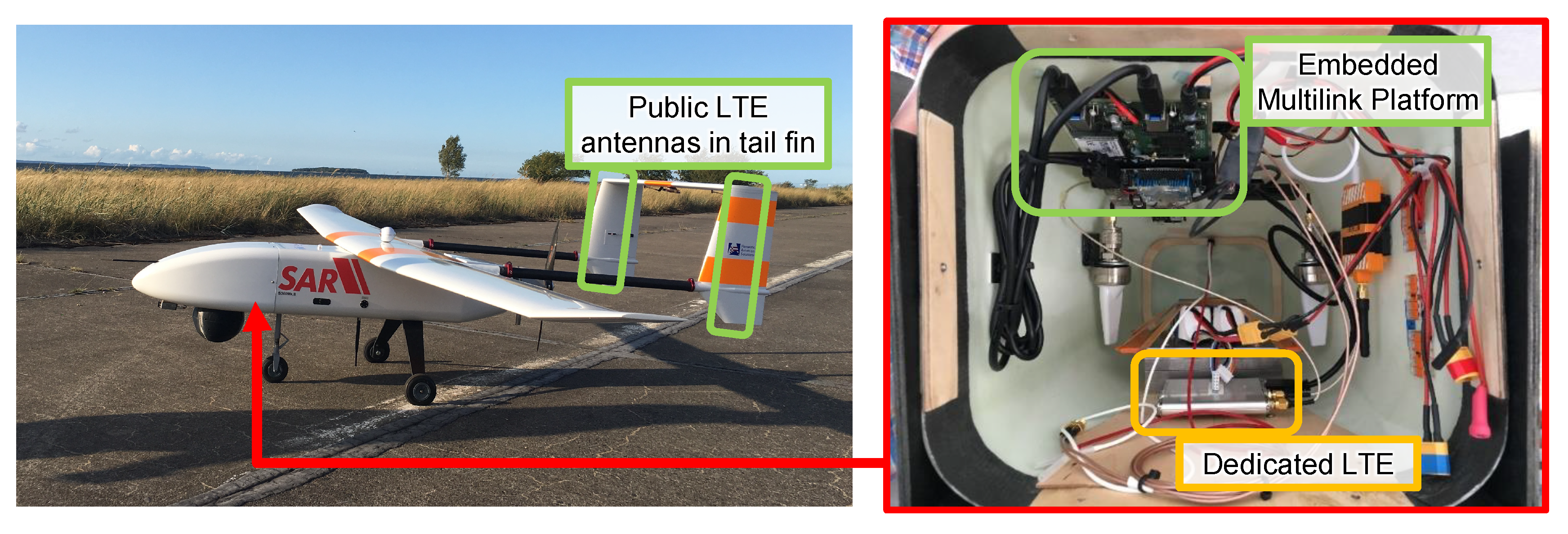
 were performed with the pictured LARUS UAV. Images: © 2020 LARUS project [1].
were performed with the pictured LARUS UAV. Images: © 2020 LARUS project [1].
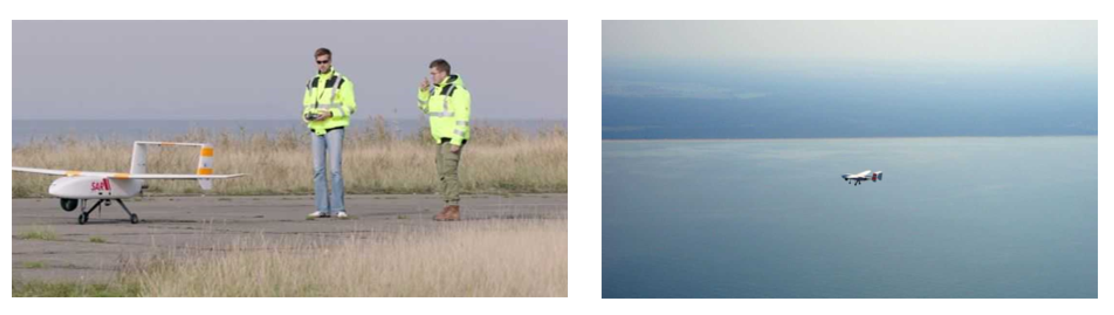
were performed with the pictured LARUS UAV. Images: © 2020 LARUS project [1]. (right). Images: © 2020 LARUS project [1].
(right). Images: © 2020 LARUS project [1].
(right). Images: © 2020 LARUS project [1].
 .
.
.
. were recorded using a manned plane, all other datasets ( – and ) were conducted using the proposed SAR UAS (c.f. Figure 3).
were recorded using a manned plane, all other datasets ( – and ) were conducted using the proposed SAR UAS (c.f. Figure 3).
were recorded using a manned plane, all other datasets ( – and ) were conducted using the proposed SAR UAS (c.f. Figure 3). .
.
.
. .
.
.
. .
.
.
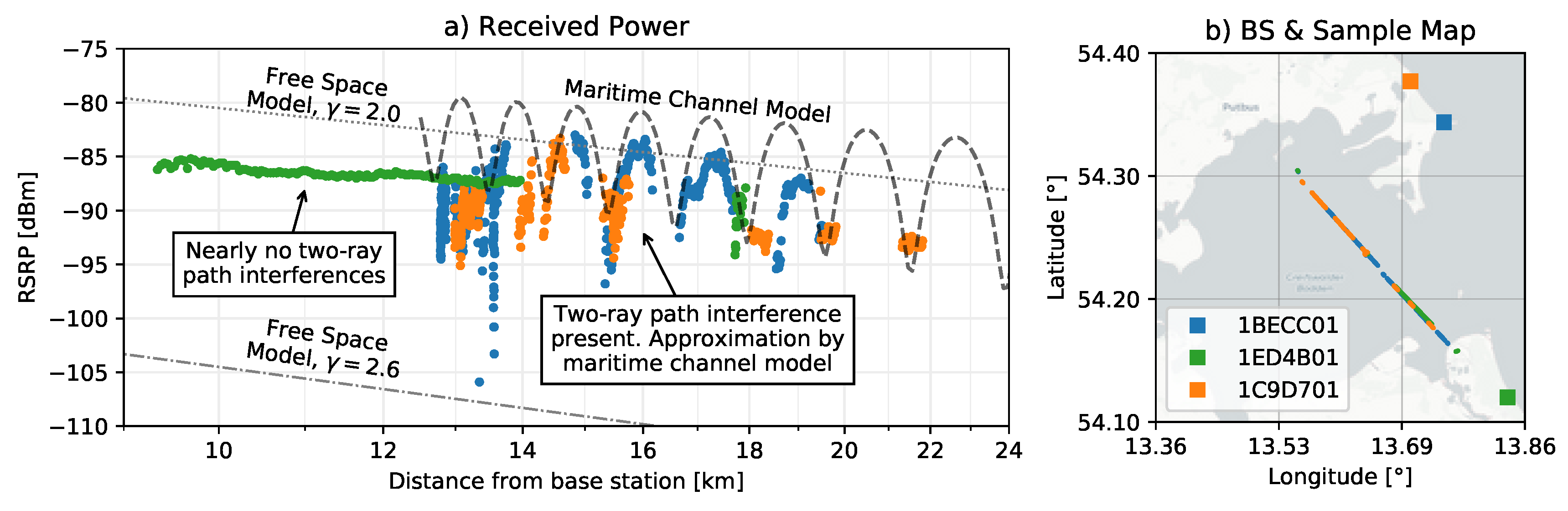
. . Whereas the left plot (a) illustrates samples of the signal strength in dependency of the UAS distance, the right illustration shows the eNB positions as well as the location, where samples were recorded. The signal of the eNB with cell id 1ED4B01 follows rural characteristics: there are no two-ray path interferences, and therefore the signal strength can be described using the free space model. The other two eNBs 1BECC01 and 1C9D701 have strong variances. These valleys can be described using the proposed maritime channel model. MNO 1, data set .
. Whereas the left plot (a) illustrates samples of the signal strength in dependency of the UAS distance, the right illustration shows the eNB positions as well as the location, where samples were recorded. The signal of the eNB with cell id 1ED4B01 follows rural characteristics: there are no two-ray path interferences, and therefore the signal strength can be described using the free space model. The other two eNBs 1BECC01 and 1C9D701 have strong variances. These valleys can be described using the proposed maritime channel model. MNO 1, data set .
. Whereas the left plot (a) illustrates samples of the signal strength in dependency of the UAS distance, the right illustration shows the eNB positions as well as the location, where samples were recorded. The signal of the eNB with cell id 1ED4B01 follows rural characteristics: there are no two-ray path interferences, and therefore the signal strength can be described using the free space model. The other two eNBs 1BECC01 and 1C9D701 have strong variances. These valleys can be described using the proposed maritime channel model. MNO 1, data set . .
.
.
. .
.
.
. .
.
.
. .
.
.
. . A live video stream payload (~500 kbps) and telemetry and control messages (~100 kbps) were continuously streamed from the UAS to the ground. MPTCP handles seamless and smooth handovers between different networks. Data set .
. A live video stream payload (~500 kbps) and telemetry and control messages (~100 kbps) were continuously streamed from the UAS to the ground. MPTCP handles seamless and smooth handovers between different networks. Data set .
. A live video stream payload (~500 kbps) and telemetry and control messages (~100 kbps) were continuously streamed from the UAS to the ground. MPTCP handles seamless and smooth handovers between different networks. Data set .


| Index | Location | Mission | Start | Stop | ||
|---|---|---|---|---|---|---|
| | Peenemünde | Single Link | 22 August 2019 | 07:17:54 | 22 August 2019 | 08:19:11 |
| | Peenemünde | Long Range | 14 September 2019 | 09:20:25 | 14 September 2019 | 10:04:34 |
| | Peenemünde | SAR Mission | 14 September 2019 | 10:15:25 | 14 September 2019 | 10:25:24 |
| | Peenemünde | Final Demonstrator | 17 October 2019 | 11:58:32 | 17 October 2019 | 12:58:31 |
 | Peenemünde | Manned Validation Flight 1 | 17 October 2019 | 11:58:32 | 17 October 2019 | 12:58:31 |
 | Peenemünde | Manned Validation Flight | 17 October 2019 | 11:58:32 | 17 October 2019 | 12:58:31 |
| | Ribnitz-Damgarten | Long Range | 28 August 2019 | 14:07:58 | 28 August 2019 | 15:26:39 |
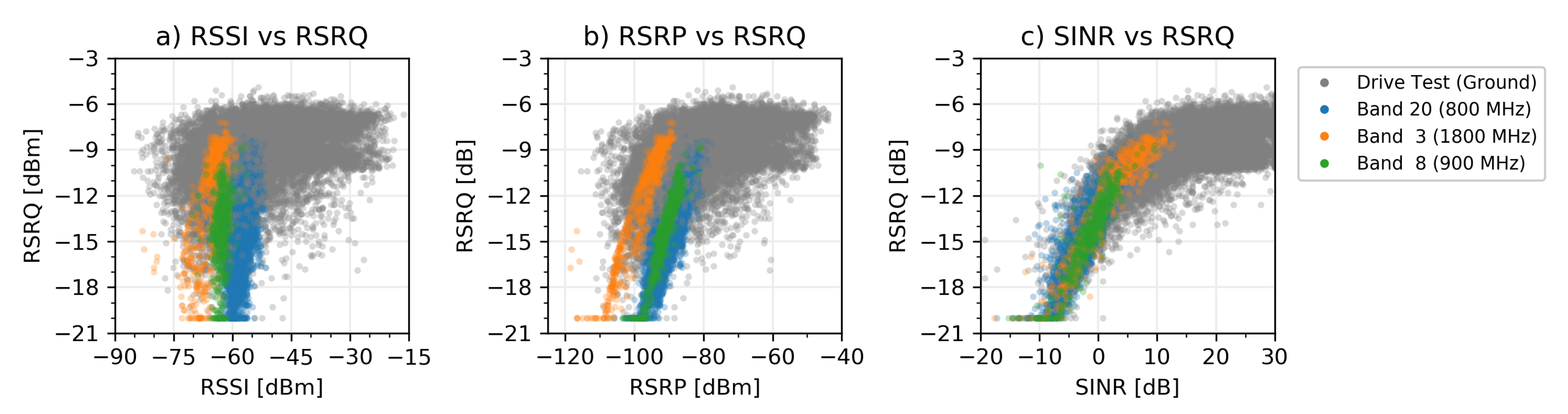
| RSRQ Flight Tests | RSRQ Drive Test (Ground) | |||||
|---|---|---|---|---|---|---|
| Band 3 | Band 8 | Band 20 | Band 3 | Band 8 | Band 20 | |
| RSSI | 0.613 | 0.281 | 0.430 | 0.070 | n/a | 0.400 |
| RSRP | 0.931 | 0.938 | 0.878 | 0.252 | n/a | 0.543 |
| SINR | 0.933 | 0.889 | 0.897 | 0.560 | n/a | 0.729 |
© 2020 by the authors. Licensee MDPI, Basel, Switzerland. This article is an open access article distributed under the terms and conditions of the Creative Commons Attribution (CC BY) license (http://creativecommons.org/licenses/by/4.0/).
Share and Cite
Güldenring, J.; Gorczak, P.; Eckermann, F.; Patchou, M.; Tiemann, J.; Kurtz, F.; Wietfeld, C. Reliable Long-Range Multi-Link Communication for Unmanned Search and Rescue Aircraft Systems in Beyond Visual Line of Sight Operation. Drones 2020, 4, 16. https://0-doi-org.brum.beds.ac.uk/10.3390/drones4020016
Güldenring J, Gorczak P, Eckermann F, Patchou M, Tiemann J, Kurtz F, Wietfeld C. Reliable Long-Range Multi-Link Communication for Unmanned Search and Rescue Aircraft Systems in Beyond Visual Line of Sight Operation. Drones. 2020; 4(2):16. https://0-doi-org.brum.beds.ac.uk/10.3390/drones4020016
Chicago/Turabian StyleGüldenring, Johannes, Philipp Gorczak, Fabian Eckermann, Manuel Patchou, Janis Tiemann, Fabian Kurtz, and Christian Wietfeld. 2020. "Reliable Long-Range Multi-Link Communication for Unmanned Search and Rescue Aircraft Systems in Beyond Visual Line of Sight Operation" Drones 4, no. 2: 16. https://0-doi-org.brum.beds.ac.uk/10.3390/drones4020016