1. Introduction
The development and improvement of drones are currently on a technological uprise. As the capabilities of drones continuously expand, so do their missions and expected performance. Many different drones are being improved to meet different customer needs for a wide variety of military, civilian, and first-responder applications. The applications of drones are constantly increasing and range from the medical utility, natural disaster management and relief, general search and rescue, agriculture, and many more [
1,
2,
3,
4]. Flapping-wing drones have recently become a highly researched topic due to their potential applications in low Reynolds number and indoor environments [
5]. One of the many applications of this specific variation of the drone is search/rescue and surveillance. Typically for these applications, it is desired to maintain an inconspicuous profile. There have been several successful developments of flapping-wing drones, but many are substantially larger than what some customers may desire. Many flapping-wing drones that have been developed and proven to be capable of all desired flight characteristics are vastly oversized, typically the size of a standard UAV (5 kg–1500 kg) [
1]. It is important when reducing the size of these drones, the maneuverability, endurance, and power are not sacrificed to meet the general consumers’ needs. To achieve customer demand, many developments have focused on producing smaller drones, including micro, nano, and pico air vehicles (MAV, NAV, and PAV, respectively) [
1]. One of the most difficult challenges is ensuring that these miniaturized drones have similar capabilities as a standard unmanned air vehicle (UAV). Although size reduction is the main objective, it is important not to sacrifice efficiency when performing size reduction. Luxuries like power, operational longevity, and maneuverability are all fundamental constraints. Many of the missions that these drones perform are in confined spaces and urban environments, making it crucial to develop an optimized product. Needs, such as agile maneuverability and long operational capabilities, must be satisfied when the final product is delivered. Since it is crucial for these systems to be efficient, the propulsion systems should be deeply investigated and optimized.
Many researchers have worked on the development and improvement of flapping-wing drone systems in various capacities. Investigations on flapping-wings range from aerodynamic predicitons to design process development and manufacturing. Many of these flapping-wings that have been developed are inspired by various animal characteristics. Most researchers have focused on monoplane and biplane flapping-wing configurations. One of the most capable flapping-wing drones that has been developed is the Delfly II [
6], which has a flight time of nine minutes with a weight of 16 g as a biplane configuration. One monoplane configuration with reported flight time is the KU-Ornithopter 06 [
7] that has an eight minute flight time, weighing roughly 30 g. Tandem wing configurations have received significantly less attention, but there are some studies that have investigated the complex aerodynamic interactions present in tandem wing systems. Researchers have utilized numerical and experimental investigations to understand tandem wing flight. Broering et al. [
8] utilized numerical simulations to investigate the impact of a tandem wing configuration in comparison with a single wing. In addition, they investigated the effects of varying phase angles on the aerodynamics of the system. In contrast, Warkentin et al. [
9] used experiments to investigate a tandem-wing configuration. In their study, the influence of the phase angle was investigated, and it is concluded that symmetrical flapping is optimal and 180-degree out of phase motion results in poor performance. Although previous researchers have presented successful flapping-wings capable of flight, these designs are not optimized and still have relatively low flight times. Based on the low flight times of monoplane and biplane systems and the underexplored capabilities of tandem-wings, they should be considered for flapping-wings as they could improve endurance and increase the potential uses of flapping-wing systems.
Since flight times of current systems are consistently low, further consideration should be given to improve the efficiency of flapping-wings. One area of interest that can be further improved to enhance flapping-wings is the propulsion system, to include actuation mechanisms and wing configurations. A number of researchers have investigated different actuation mechanisms and outlined their advantages and disadvantages [
10,
11,
12,
13,
14,
15,
16,
17,
18,
19]. Hassanalian et al. [
10] discussed the common mechanical actuation mechanisms and presented their respective advantages and disadvantages. The main difference in mechanical actuation mechanisms are the weight to achieve a desiered flapping frequency as weight can be reduced by integrating the gear train into thte actuation mechanism. In addition, electro-mechanical and piezoelectric actuation mechanisms have been investigated which can achieve required flapping kinematics, flapping frequencies, and flapping angles, at low weights [
18,
19]. Further investigations on propulsions systems, actuation mechanisms, and wing configurations, could aid in the development of more efficient flapping-wing systems.
Another component of the propulsion system that could be optimized to enhance the performance of flapping-wings are the wings. There is a wide variety of wing configurations possible for a flapping-wing. Flapping-wings have been developed with monoplane, biplane, and tandem-wing configurations. As previously mentioned, monoplane and biplane configurations have shown low fligh times and tandem wing configurations should be further explored. Flapping-wing systems can also vary in angle of attack and spar configurations. Ideal angles of attack have been presented from theoretical outlook but an experimental investigation on the aerodynamic force production for different angles of attack is missing in current literature. Additionally, spar locations and layout have been shown to have a large impact on the integrity and performance of the flapping-wing but deeper investigation into this is needed. Few experimental studies have been conducted that focused on the propulsion systems of flapping-wings. Wu et al. [
20] used a thrust stand to investigate the impact of spar locations for a range of flapping frequencies. Jones et al. [
21] tested propulsion from a flapping-wing under various circumstances using a low-speed wind tunnel.
Bio-inspired efforts for UAVs have typically been investigated in an effort to enhance performance, but one intriguing characteristic of flapping-wing drones is their inherent bio-inspired design, giving them the capability of remaining inconspicuous. However, as expected, these drones have vast limitations when it comes to power, efficiency, and maneuverability. Having an operational drone of a smaller size will meet the demand of having a discrete drone mimicking an insect or bird. Many researchers are focusing on flapping-wings in an effort to improve these bio-inspired flyers and move towards bio-mimicked systems through aerodynamic investigations and actuation mechanism optimization [
22,
23,
24]. In addition, a number of researchers have focused on the performance structure of natural and robotic flyers’ wings in an effort to further optimize these bio-inspired and bio-mimicked systems [
25,
26,
27].
The objective of this study is to investigate the propulsion system of a flapping-wing micro air vehicle (FWMAV). To this end, a design process is used to develop a bioinspired FWMAV. The manufactured system is used for experimental investigations on the propulsion system to identify how two actuation mechanisms affect the performance and how various wing configurations impact the aerodynamic force production from the system. A mission is laid out to determine desired flight characteristics and mission requirements. Based on the desired flight characteristics, the wings and tail are selected, and a weight estimation is carried out to determine the weight range of the system. Once the size and weight of the drone are determined, different actuation mechanisms are investigated, two are selected for implementation into the flapping-wing system, and the system is experimentally tested. First, the system is tested using a thrust stand to determine the optimal wing configurations, and based on this testing, a rotating wing configuration is designed and integrated into the system. The conclusions from this work can be used by researchers and designers for the development of flapping-wing micro air vehicles. The rest of the paper is laid out as follows: materials and methods are discussed in
Section 2, to include the sizing process, manufacturing, and experimental setups used throughout this study.
Section 3 outlines the results and discussions from experimental testing, and
Section 4 presents conclusions from this work.
2. Materials and Methods
2.1. Sizing Process of the Flapping Wing
As there are a number of drone configurations, they can vary in size greatly. This work is focused on the MAV class, which is defined to range in wingspan from 15 to 100 cm and in weight from 50 to 2000 g [
28]. To begin the design process, a general weight estimation is necessary, and in this work, the drone to be developed is estimated to weigh approximately 100 grams. Once this general weight estimation is determined, the process of selecting the components of the drone, such as hardware and wings, can begin. A tandem wing configuration is considered in this study, inspired by a dragonfly due to its ability to perform hovering, forward, and backward flight [
29]. Having such capabilities would make a FWMAV competitive in the market of surveillance and reconnaissance missions. Due to the intended size and weight of the drone, it is easy to determine the approximate wing dimensions, such as wingspan and wing area for a FWMAV drone.
To begin the sizing process that must be carried out, a theoretical approach is taken that outlines the estimated weight percentage for different components on the system. This approach is based on other flapping-wings and is presented by Hassanalian et al. [
28]. Since the FWMAV to be used in this work is estimated to be about 100 grams, the estimation determines that the power plant, payload, battery, avionics, and structure should be 23%, 2%, 24%, 13%, and 38% of the total weight, respectively, which are determined based on a statistical analysis considering previous flapping wing systems’ weight distributions. The initial weight estimation is used to determine these component weight estimations and provides a rough idea of the final weight of the system, but a final weight estimation is carried out farther in the design process.
Table 1 provides the weight contributions for each component where
denotes the weight of the motor and speed controller,
represents the weight of the payload (camera, sensors, etc.),
is the weight of the battery,
denotes the weight of the receivers and other navigation systems, and
is the weight of the structure (fuselage, tail, actuator, and wings).
Knowing the anticipated weight of the system, all electrical components can be selected based on the statistical weight of previously designed flapping-wing drones. In total, 60 grams are dedicated to the electrical components of the system and selected accordingly. For the remaining structural aspects, a computational approach is taken to develop a general weight estimation. For each component, the density of the materials are multiplied by the volume to find weight. Standardizing the wings to be rectangular profiles and the tail to be triangular, the component sizes could be calculated. For the more abstract components, like the housing and actuation, the volume is determined using Fusion360. Once a general design is composed, the volume is found and used to obtain the estimated weights.
Table 2 summarizes the calculations conducted to determine the weights of all components in the integrated system. Using these estimated weights, a required flapping frequency can be calculated.
After estimating the weight of the flapping-wing, a more accurate assessment of the required flapping frequency can be achieved. According to Hassanalian et al. [
16], the desired frequency for flight is calculated using Equation (1). Data was collected on 47 different birds that required relatively low frequencies for flight. Based on mass (
), system length (
), surface area (
), and air density (
), a flapping frequency (
) of the system is determined. To calculate the flapping frequency for FWMAVs, a correction factor,
ξ, is introduced [
16]. This correction factor varies depending on the size of the flapping-wing under consideration and for this size, it varies from 2.5 to 3.1 [
28]. For the flapping-wing drone under investigation, the final system weight will be 116–140 grams, with a length of 11.5 in, and a theoretical surface area of 132.65 in
2 (determined by Fusion 360), and the required flapping frequency is calculated as follows:
The final design of this flapping-wing has a flight speed, U, of 8 m/s with a half flapping angle, φ, of 30 degrees. Based on this range of flapping frequency, and operating parameters the estimated Strouhal number, defined as , falls in a range of 0.26–0.79.
2.2. Wing Selection and Manufacturing
From the sizing and weight estimation, it is determined that the final system will have 116–140 grams with a wingspan of 16.5 in. As previously mentioned, a bumblebee wing shape is considered for the four wings. This selection is based on the studies carried out by Hassanalian et al. [
18,
19] where seven different insect wings were studied and compared to determine the optimal wing shape for hovering and forward flight. For the hovering flight study, a quasi-steady theory is employed to determine the optimal wing shape for two cases, one considering all wings to have an equal wing surface and one with all wings having an equal wingspan [
29]. Another study [
30] was conducted using a strip theory method to study the aerodynamic properties of each insect wing in forward flight, again considering cases of equal wingspan and equal wing surface. From these studies, the bumblebee wing is considered due to its consistent performance in each flight mode when considering both equal wingspan or wing surface. Although the bumblebee was not necessarily the top performer for all considered scenarios, it consistently performed well and has a relatively simple shape that facilitates manufacturing. Other wing shapes, such as the twisted parasite, performed strongly but do not lend themselves to manufacturing or tandem wing configurations. The twisted parasite performed strongly in most scenarios considered, but its low aspect ratio would make it difficult to integrate into a tandem wing configuration because of its large chord length.
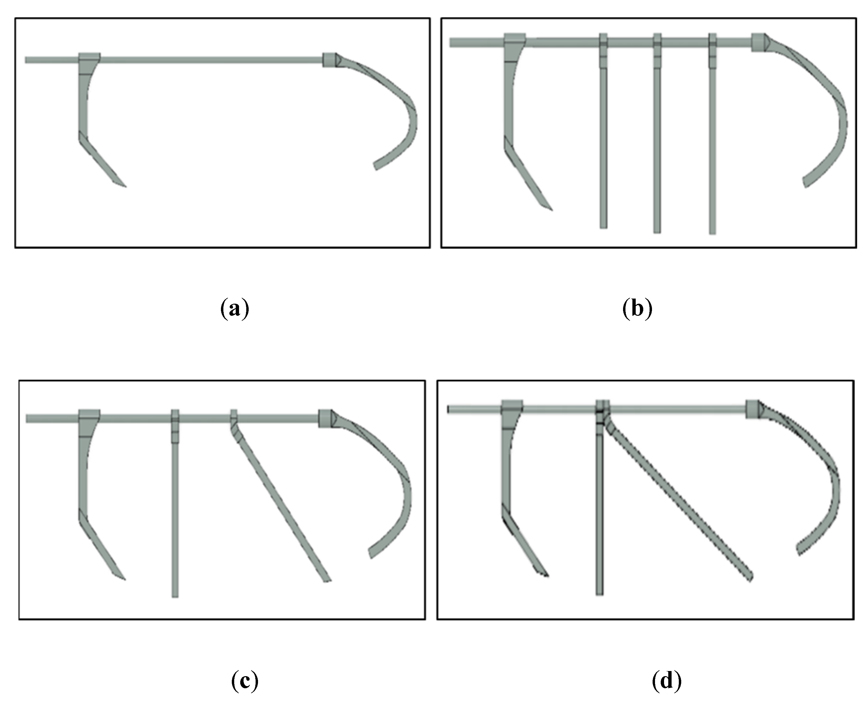
Although the general wing shape has been decided, the location of the spars that provide rigidity to the wing must be determined. In this study, four-wing configurations are considered to investigate the impact of the placement of the spars on the performance of the system. These wing configurations are selected to investigate a range of different configurations. The first configuration is a wing with no carbon stiffeners to investigate how the lack of carbon spars may affect the wing performance. Wing configuration 2 has only vertical spars, and configurations 3 and 4 have one vertical spar with one diagonal spar to investigate how the placement of a diagonal spar could affect wing performance. To determine the optimal wing configuration, an in-depth study purely focused on wing configurations using finite element analysis (FEA) simulations and experimental investigations should be performed. The variable placements of the ribs throughout the wing profile will also help determine which of the designed wings has the lightest configuration and what the most durable design is. The four configurations are shown in
Figure 1.
A similar approach and materials are used in the manufacturing of each wing. A combination of additive manufacturing (3D printed PLA), carbon spars, epoxy, and Mylar are used to build each of the wings. These materials are chosen due to their availability, cost, ease of manufacture, and utility in their selected area. The leading edge of each wing is a 1/8 in cylindrical carbon spar with 3D printed components connected to form the overall profile and aid as the clips for the 1/2 in × 1/32 in carbon spar ribs. Using a five-minute epoxy, all the skeletal components of the wing are secured to the leading-edge spare to define the profile of the bumblebee wing. Once the overall skeletal structure of the wing is established, a thin Mylar film is adhered to the structure. Mylar is a very light but durable material when properly adhered to a structure, making it a good material for the membrane of a flapping-wing system. To properly adhere the Mylar to the structure, it is crucial to secure Mylar to a cleaned surface. Adhesive spray is applied to the skeletal structure of each wing before placing it on the outlaid, Mylar surface pulled tautly. After properly adhered, a 1/4 in piece of tape is applied to the trailing edge of the wing, which adds rigidity and completes the profile of the wing. An X-Acto knife is then used to cut the wing from the Mylar surface. For each of the designed wings, four wings are built to accommodate for the tandem wing configuration of the drone.
One consideration in the selection of the optimal wing is the weight. A minimum of four wings are built for each wing design because of the tandem configuration, and there is a possibility of variability in each wing through manufacturing. Therefore, each wing is weighed, and the average weight is calculated. The average weight of each wing is given in
Table 3, and an example of each fabricated wing is provided in
Figure 2. Once manufacturing is completed, the wings are integrated into the final system for thrust testing. Through thrust testing, the performance of each wing is investigated to make a final choice for the optimal wing design for the system.
2.3. Actuation and Fuselage Section and Manufacturing
There is a large variety of actuation mechanisms used in the manufacturing of drones [
10,
11,
12,
13,
14,
15,
16,
17,
18,
19]. When selecting these mechanisms, many crucial factors must be considered and compared to select the appropriate actuator for the desired drone design. Currently, there are five primary mechanical actuation devices used for flapping-wing drones, each has advantages and disadvantages. The five mechanical actuation mechanisms commonly used or inspired from are the single-crank mechanism, a single-crank mechanism with an offset, slider-crank mechanism, double-crank mechanism, and the alternate configuration [
10]. Some other actuation mechanisms are electro-mechanical or piezoelectric, but they are not considered in this work [
18,
19]. Based on the advantages and disadvantages of each mechanism, two different mechanisms are selected to be designed, built, and integrated into separate systems.
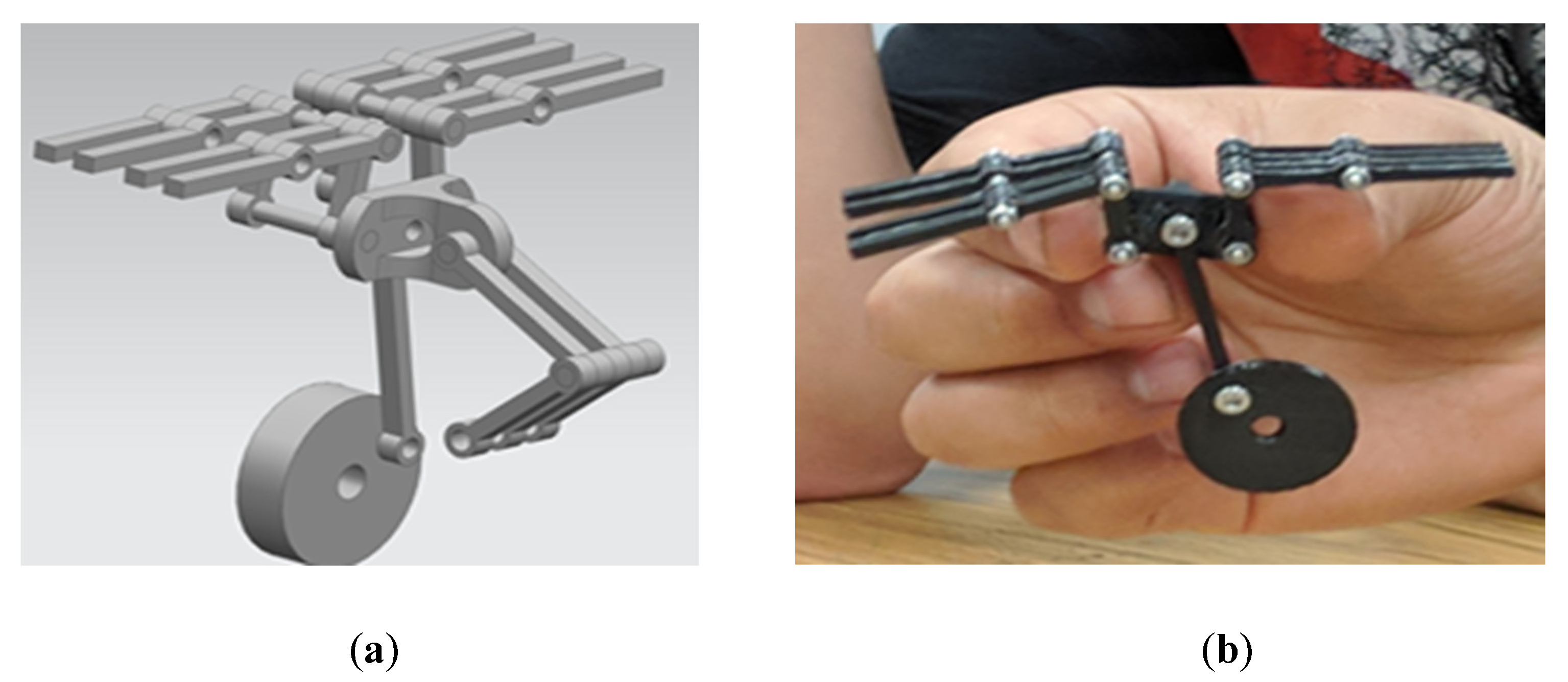
For the first FWMAV prototype, a hybrid actuation mechanism is proposed. This hybrid mechanism takes properties from a slider-crank mechanism and an alternating crank mechanism. The combination of these two actuation mechanisms provides a lightweight system while maintaining harmonic flapping frequencies between the four wings. The slider component of the slider-crank is integrated into the mechanism to convert the circular motion of the crank into a vertical upward and downward motion. By constraining the motion of the push rods, it is easier to guarantee the success of the system while in operation. Two fixed pivot points are incorporated into the hybrid actuation mechanism as well; mimicking the alternating mechanism. The prominent feature of mimicking the fixed pivot points of the alternate crank mechanism is that symmetric motion can be achieved across all the mounted wings. With this new design in mind, a general model of the actuator can be made, and a fuselage can be designed to accommodate the actuation mechanism. The model and fabricated mechanism are shown in
Figure 3.
The fuselage housing is designed to fully incorporate the hybrid actuation mechanism into the system, house a gear train, secure all electronics (battery, receiver, electronic speed controllers (ESCs), etc.), mount a motor, and provide mounts for the designed tail. The design is comprised of multiple vertical columns that house bearings for the shafts of the gear train to ensure easy rotation. The motor, a MultiStar Viking 1308-4100KV Brushless motor, is secured in the fuselage and has the driving gear secured to its shaft. The desired maximum flapping frequency of the system is 20 Hz, and a gear train is designed accordingly. Six gears are used in the complete gear train to accomplish this reduction, all stainless steel to reduce wear on the gear teeth.
Figure 4 illustrates the fully integrated system with all components.
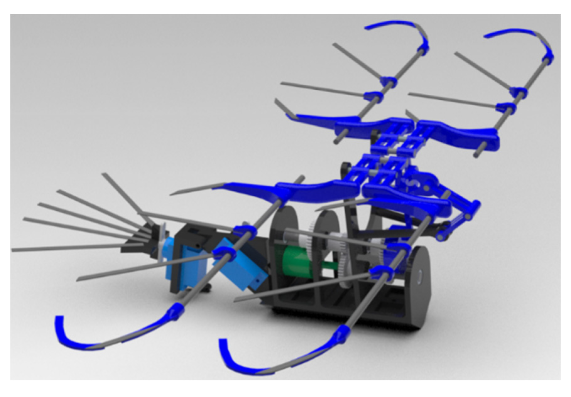
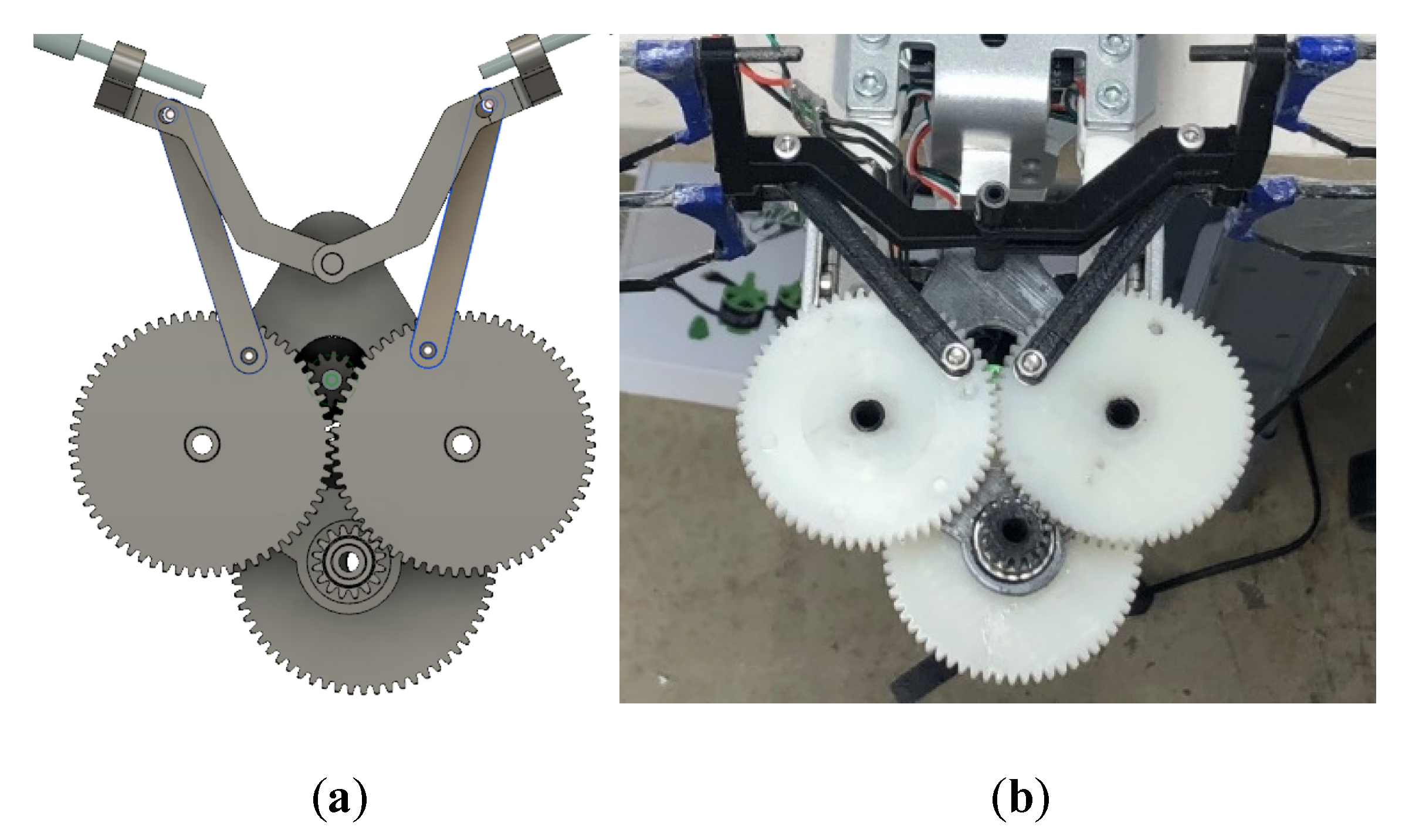
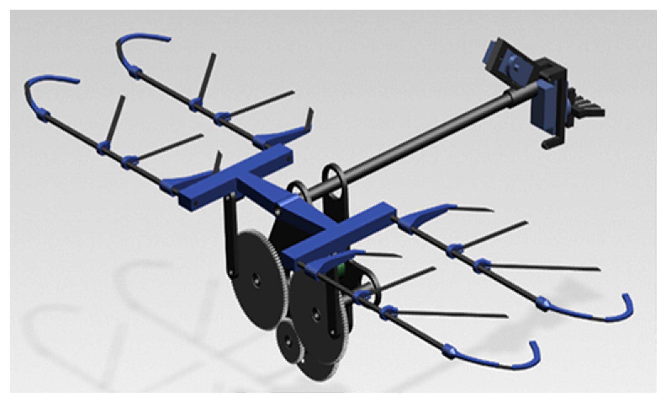
For the second FWMAV, the double crank mechanism is considered for the actuation. This actuation system is typically regarded as one of the heavier mechanisms; however, the novelty of this design is that the actuation mechanism can be directly integrated into the gear reduction system. Two push rods are mounted on the front of the larger gears. The rods are then attached to the rockers (wing mounts), which are customized to mount four wings on a level plane. As the gear train completes its rotational cycle, it will adjust the positions of the push rods, resulting in a flapping motion at the wing mounts. This not only saves weight but also reduces the necessary manufacturing time to build a fully integrated system. With fewer moving components needed to produce flapping, the system is optimized, and the overall risk of system failure is substantially reduced. The actuation mechanism/gear train of the second concept is shown in
Figure 5.
Using the double crank mechanism, a new housing needed to be designed to house the components of the system, as shown in
Figure 6. With this optimized design, the housing is adapted to be more compact, greatly reducing the amount of required materials and the weight of the overall system. Once again, this new fuselage is designed to house the motor, gearbox, required electronics, mount the actuation, and the wings and tail of the system. A central spar is incorporated to secure the fuselage, provide fixed pivot points for the wing mounts, and to mount the tail.
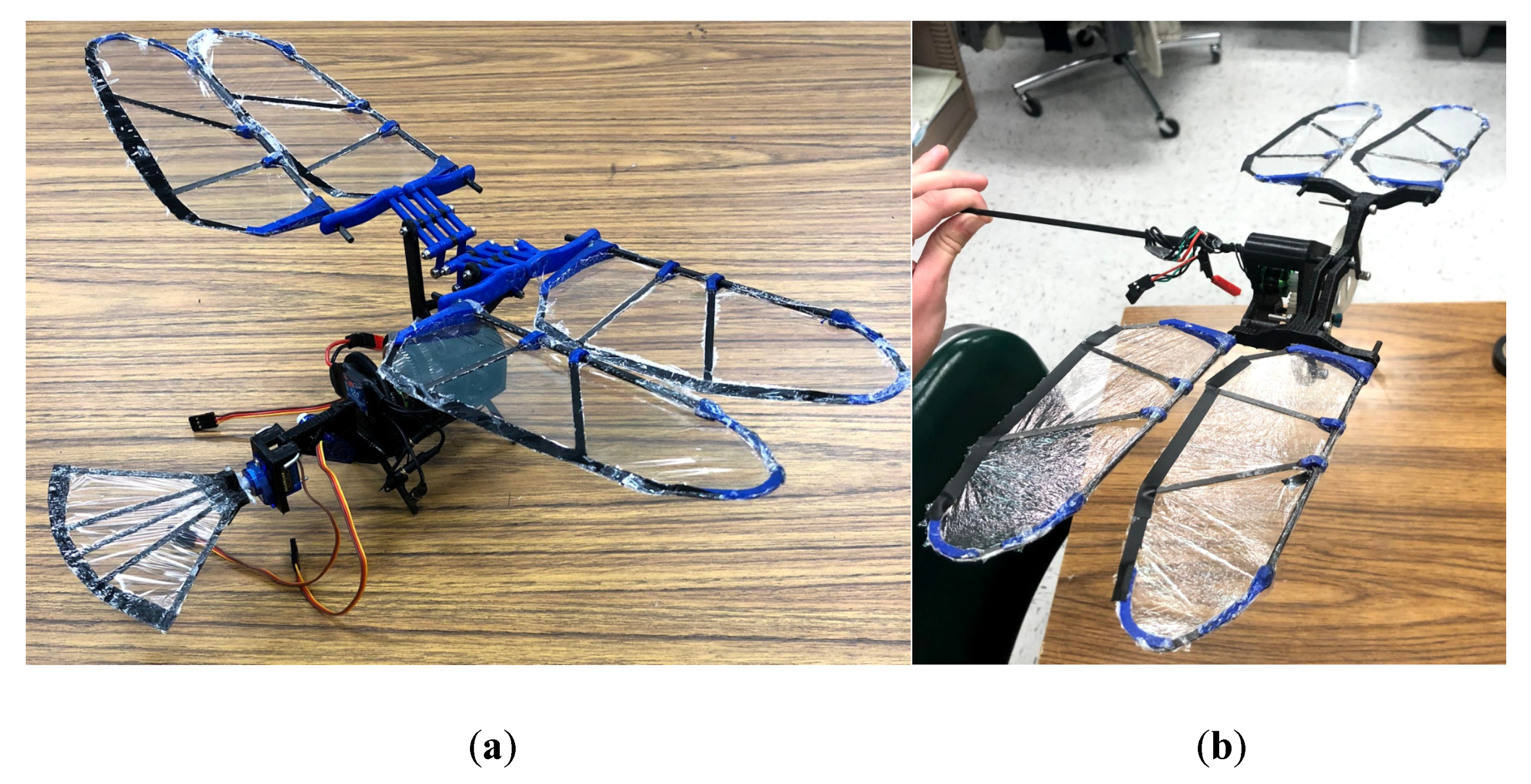
Each of the two systems was built, and ground tested. First, the systems are tested without wings mounted and then again with the wings mounted. FWMAV 1’s actuation mechanism is functional and is capable of operating at frequencies upward of 20 Hz. However, when mounting the wings to the system, the rotating wings cause the fuselage mount to bend, causing the gears to jump track, leading to system failure. FWMAV 2 is able to perform both tests as expected and maintained its overall structural integrity throughout each phase of testing. Examples of the two fully integrated and tested systems are shown in
Figure 7.
It is also important to consider the weight of each of these systems and how they compare in reference to the theoretical weights. As can be seen in
Table 4, FWMAV1 far exceeds the weight limitations intended for the design of the system. Because of the design of the housing mechanism and the use of stainless-steel gears for the gear train, the weight of the final system is 218.5 grams, 218% above the intended weight of the final system. A vast majority of the weight in this system is from the structural makeup of the system and vastly exceeds the theoretical weights projected. The second FWMAV drone is significantly lighter, and a large part of this reduction can be credited to the reduced housing design, the innovation of integrating the gear train into the actuation and using nylon gears.
It was clear from the ground testing and the general weights of the two systems that the second system should be used in the final testing. Not only was it able to perform, but it also falls within the previously estimated weights.
2.4. Thrust Tests and Free-floating Lift Test: Experimental Procedure
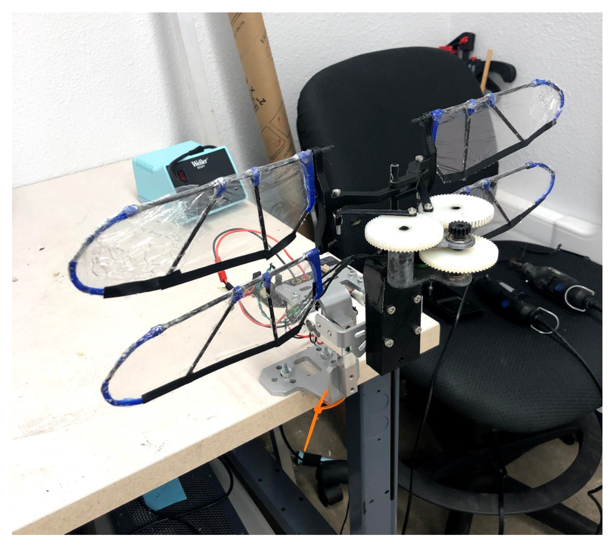
After manufacturing the fully functioning system, the FWMAV must undergo a series of experiments to determine the overall performance of the system. Several different approaches are used to collect data on the system’s performance, and many visual experiments are conducted to observe and determine how the system will function. Thrust stand experiments are carried out using an RCBenchmark series 1580 test stand, to collect the thrust output produced throughout a flapping cycle of the system. Using data collected from the thrust stand experiments, the flapping-wing system is optimized to improve positive thrust output. All data and observations collected in these series of experiments are used to adjust the system in order to improve its performance. The thrust stand is designed to test the thrust of a standard quadcopter motor, so a mounting system was developed for the flapping-wing drone. Using 3D printing, a rectangular block was printed with holes placed in the appropriate places, so bolts could be used to mount the modification to the stand. The central spar of the system can be placed through the block, in an additional hole incorporated in the design, so the drone could be secured in a vertical orientation with respect to the thrust stand. When in a flapping motion, the stand can oscillate with respect to the thrust produced by the system. The flapping-wing and mount are presented in
Figure 8.
This strategy for mounting the drone, positions the drone so that the thrust generated by the down and upstrokes of the system could be recorded. Previous works have ensured that the height of the mounted drone would not interfere with the data collection resulting in incorrect results. Thrust tests are first conducted on the four different wing designs discussed previously. From the performance outputs of these thrust tests, the highest performing wing is selected for the rest of the experimentation. Using the optimal wing design, the system is tested at different angles of attack to determine the configuration that produces the most positive lift for the flapping-wing system. After determining the optimal angles for thrust, a new wing mount is designed to allow the wings to rotate while in a flapping motion. Again, thrust tests are conducted to observe the performance of this new wing mount design. The data collected in this final thrust test is compared to the results of the previous experiments to showcase the system’s improvement with this implementation. Each of these tests is powered using a DC power regulator to ensure consistent and continuous power supply.
For each of the thrust tests, five different flapping frequencies are tested, namely, 2, 4, 6, 8, and 10 Hz. Using the RCBenchmark software, different currents are set to meet the specific frequency values for each test. Each of the frequency tests is conducted five times to collect a wider range of data. Average thrust values from the five tests are used throughout the rest of the work to reduce the amount of potential error in the data collection. The thrust stand used does not collect every data point throughout a thrust test, which in the case of a quadcopter motor, is not an issue due to the continuous thrust produced. With a flapping motion, different thrusts will be experienced throughout a flapping cycle. The thrust stand has an 8 Hz sampling frequency that often results in inconsistent graphs that will not represent or mimic one another [
31]. Each experiment conducted will have a different range of data points that will not result in the smooth sinusoidal like plots that would be expected from a flapping cycle. This is one of the primary motivations for conducting each test multiple times in order to obtain a large range of data.
The four different wings with varying locations of carbon spars are built and tested. For each of the designs, four wings are built and mounted on the wing mounts (actuation rockers) at a neutral angle of attack. It is crucial that when mounting the wings, each wing is on an equal plane, to ensure high-quality data. Each of the four wings is tested across the five frequency values. For each frequency value, five tests are conducted to gain a wider data pool for analysis. The thrust stand being used has a maximum sampling frequency of 8 Hz but has shown to be inconsistent, leading to erratic data at times.
Based on the data collected in each of the thrust tests for each wing, the maximum positive thrust is determined for each wing set and each flapping frequency. From each of the flapping frequency tests conducted, the maximum positive thrust values are recorded. Given that the test is run five times for each flapping frequency, an average of the maximum thrust is used to create a general thrust curve for each wing set.
3. Results and Discussion
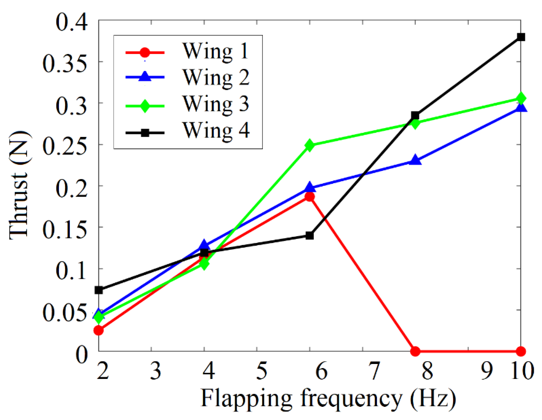
As mentioned before, thrust stand experiments were carried out to investigate the aerodynamic force generation capabilities of various wing configurations and to investigate how that force generation changes as the flapping frequency is varied. All results are presented as thrust but can be considered for lift as well, depending on the orientation of the vehicle in flight. As can be observed in
Figure 9 and
Table 5, it is clear that Wing 1 fails at frequencies that exceeded 6 Hz. This ultimately rules this wing out from the final selection and emphasizes the need for spars in the wings of flapping-wing systems to enhance the integrity of the sysem. Based on the performance of the other three wings, each is a viable candidate for final selection. Wing 2 produces an average maximum thrust of 0.294 N, Wing 3 has a maximum of 0.305 N, and Wing 4 has a maximum thrust of 0.379N. Based on these findings and available data, Wing 4 is the most optimal for the final system as it generates the most thrust and is the lightest of the three viable wings. Although this investigation shows the ideal wing from the ones under consideration, an in-depth investigation using FEA simulations could provide more detail on the ideal configuration of spars for a flapping-wing. The ideal configuration will also depend on wing shape, size, and flapping parameters but this investigation shows that these are worth considering in order to optimize the performance of flapping-wing vehicles. These results compare well to experimental investigations carried out by Jones et al. [
21] under low flight speed considerations. In addition, the tight grouping of these wing configurations is confirmed by Wu et al. [
20] who investigated various wing configurations. Although different wing configurations were investigate than those in this work, at low frequencies, the thrust generation is very similar between the different wings. These agreements with previous works, validates the experimental procedure being used in this work.
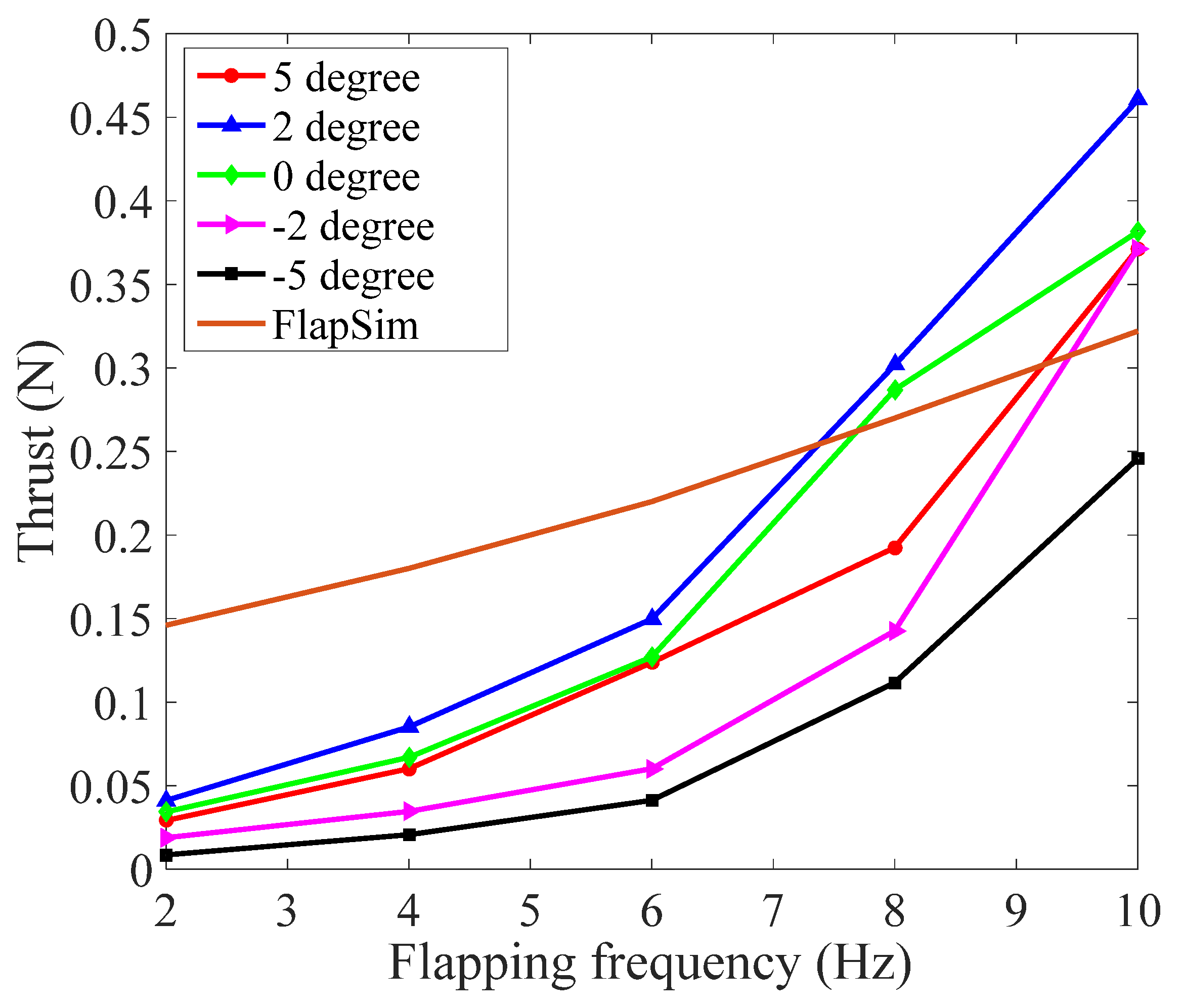
The next series of thrust tests were performed to determine which angle of attack of the wing produces the most positive lift while in a flapping cycle. For these tests, five different angles of attack were considered and tested: −5°, −2°, 0°, 2°, and 5°. Like the tests done for the different wing designs, each of the angles of attack was tested at flapping frequencies of 2, 4, 6, 8, and 10 Hz. For each of these tests, five different samples were taken to give a wider range of experimental data to analyze. It should be noted that a wing set is built for each of the different desired angles.
After each wing was built, it was integrated into the system by mounting it to the 3D printed rocker (wing mount) that mounts to the central spar of the system. The desired angle of attack for each of the wings was established before being fixed in place with epoxy. Accurately mounting the wings at specified angles of attack is critical to the successful operation and flight of the system. Once the wings were secured in the system, the FWMAV was mounted to the thrust stand to conduct the tests. Before determining the optimal angle for positive thrust, it was essential to compare the overall performance of each angle by comparing the average maximum thrust of each angle of attack at different flapping frequencies.
Figure 10 and
Table 6 show the average maximum thrust produced for each of the different angles of attack configurations. In addition, an approximation based on FlapSim, which employs a modified blade–element momentum theory, is included in
Figure 10 to show that experimental results are in general agreement with simulations for higher flapping frequencies [
32,
33,
34]. Discrepancies between FlapSim simulations and experimental data can be attributed to a few things. FlapSim does not account for material characteristics and flexibility of the wing structure which can cause significant differences in the result. Additionally, the kinematics entered in FlapSim are typically not exactly replicated in actual flight resulting in discrepancies in the data. Lastly, FlapSim considers an airfoil for the wing, which is different than the manufactured wings. Although these reasons can cause differences in real-world data and FlapSim results, the results are still in generally good agreement.
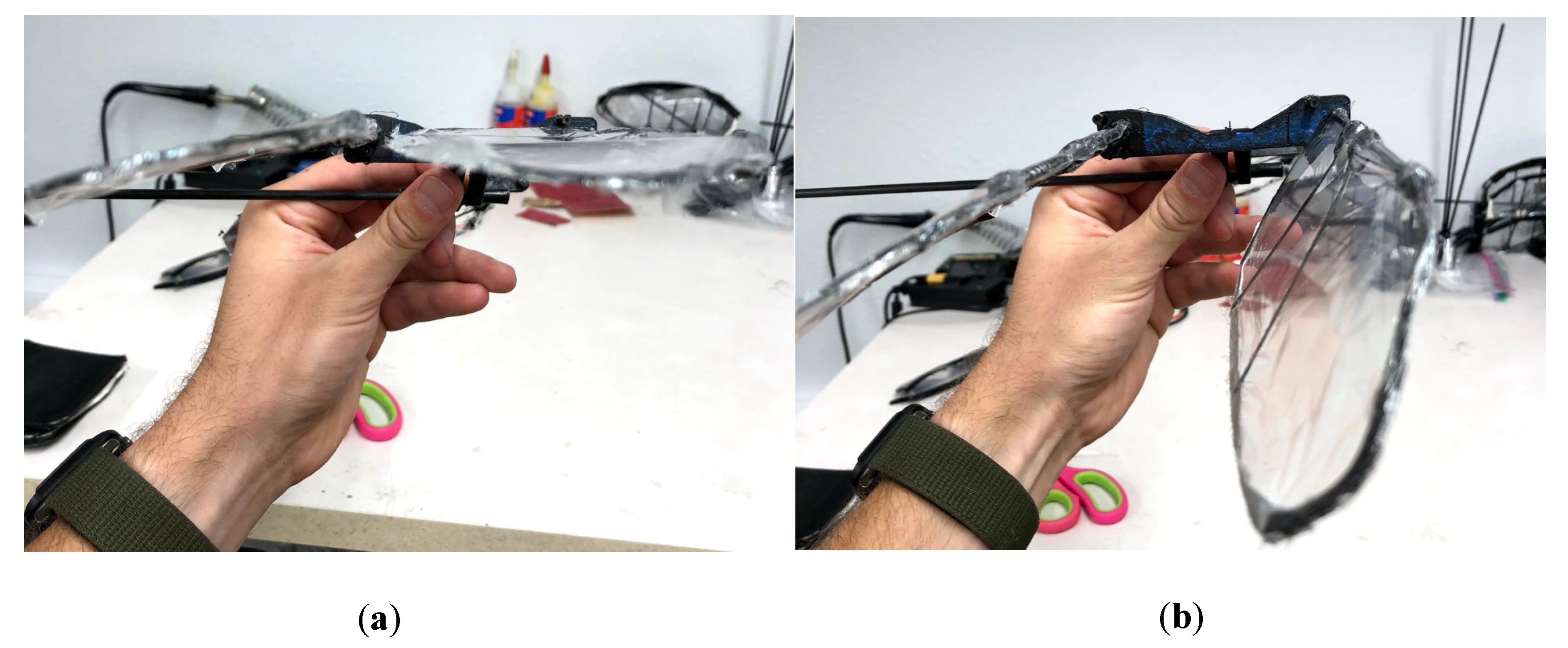
From the findings of the varied angles of attack tests, it was concluded that the most desirable angle for positive thrust is 2°. For the system to produce positive thrust throughout the full flapping cycle, a new wing mount was designed to allow the wings to rotate while in a flapping cycle. The design utilizes the same principle as the previous wing mounts; however, the structure size is increased, and holes are implemented for the insertion of carbon spars. After printing, the spars were inserted into the wing mounts to act as barriers for the rotating wing, preventing the wing from over-rotation. On the downstroke mode, the wings will rotate to positive 2° using the force of the air to complete this action. The carbon spar will prevent the wing from exceeding the intended 2°. On the upstroke, the air will force the wings to rotate to a 45° position. Once again, the carbon spar will stop the wings from rotating past the designated 45°.
The intention of this design is to reduce the negative lift experienced in a full flapping cycle. The position of 45° is determined through a series of experiments. Findings proved that any angles exceeding 45° tended to cause the rotation of the wings to fail when in a flapping cycle, rendering the design useless. The novelty of the design is how it invokes this rotation without the use of any motorized electronics (servos, motors, etc.). The design still capitalizes on the rotation of the wings but minimizes the weight and complexity of the system by refraining from the use of motorized assistance, as presented in
Figure 11. Although the design is slightly larger than that of the previous wing mount, the weight sacrificed for the design is negligible compared to that of a motorized solution.
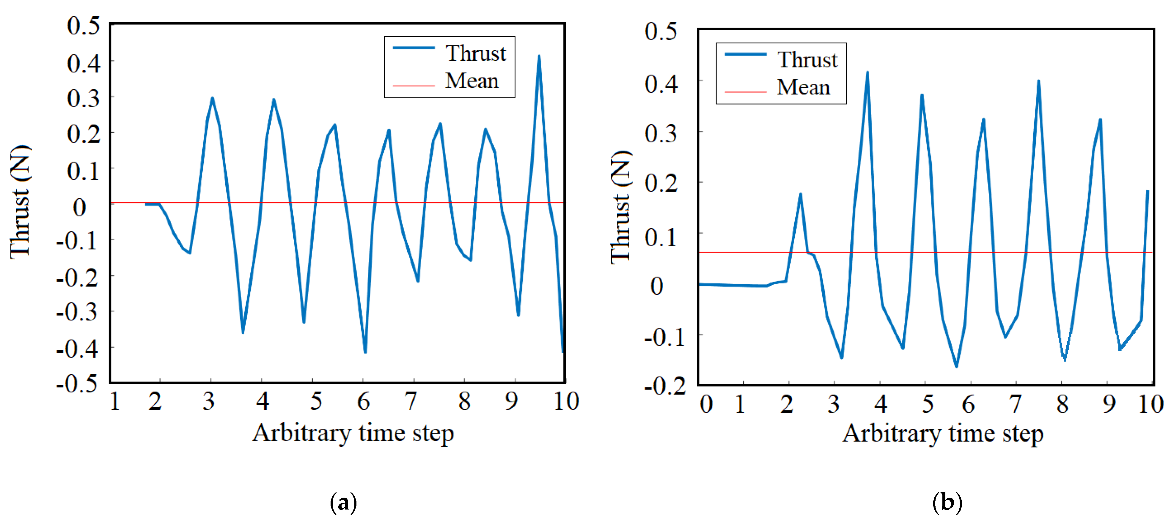
Once the new design was built and integrated into the system, additional thrust tests were conducted to validate the overall performance of the configuration. The same experimental test approach was performed on the rotational wing configuration for different wing designs and at a fixed angle of attack. After being mounted onto the RcBenchmark thrust stand, each of the five different frequencies was tested. Each of these tests was conducted five times to increase the range of data collected in the experiments conducted. Once the data was collected, it was important to compare the findings of the rotating wing to the fixed-wing configurations, specifically the 2° angle of because of how well it performs compared to the other angles of attack. First, a comparison was carried out for the overall thrust curves of the fixed 2° and the rotating wing configuration for a 10 Hz flapping frequency, as shown in
Figure 12.
As can be seen from the curves in
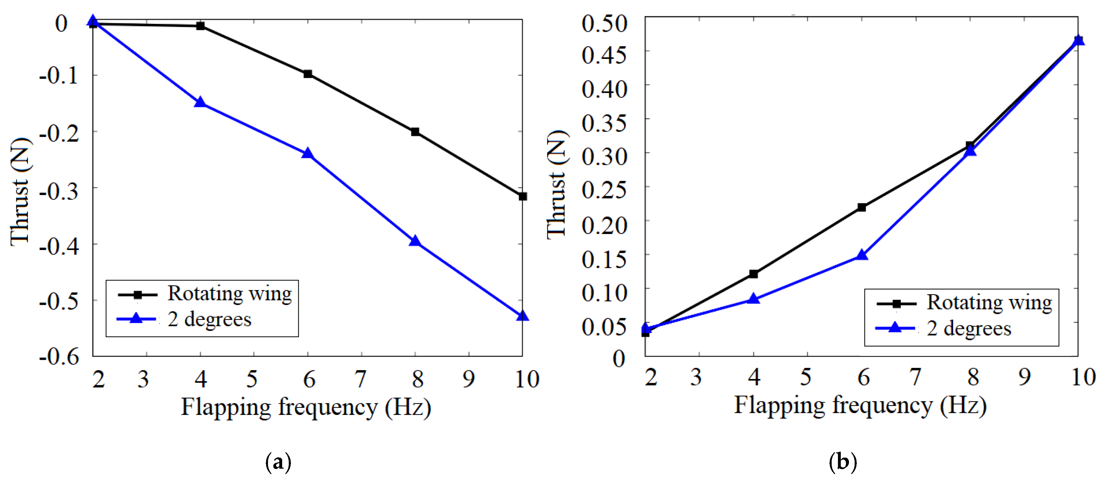
Figure 12, the rotating wing has significantly less negative lift, which results in a positive lift profile throughout a flapping cycle. To analyze how much this new configuration impacted the system,
Figure 13 compares the average positive and negative thrust produced by the 2° fixed-wing and the rotating wing. It follows from the curves in
Figure 13 that the rotating wing configuration significantly reduced the amount of negative lift experienced on the upstroke of the flapping frequencies.
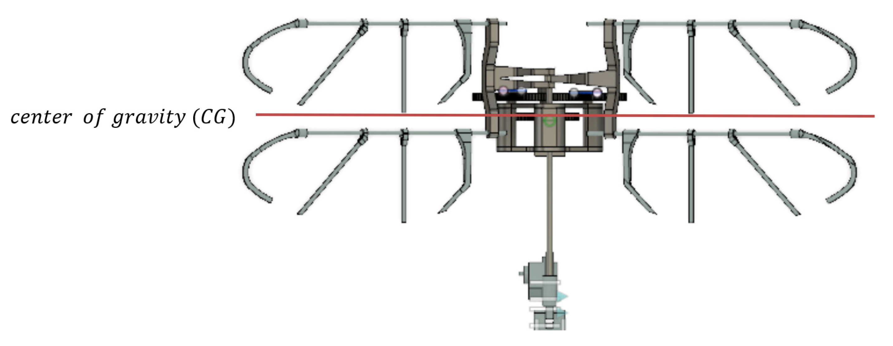
In preparation for a final free-floating lift test, the remaining electronics were integrated into the system. The selected battery, electronic speed controller (ESC), and receiver were all placed systematically on the drone. The weight distribution of the drone was crucial for a successful flight. In order to avoid any large destabilizing moment during the tests, the weight was distributed along the fuselage so the center of gravity could be in the center of the four wings, as shown in
Figure 14, slightly ahead of the aerodynamic center, which is directly between the fore and aft wings. The locations of the aerodynamic center and center of gravity resulted in a nose down configuration. In this design, a bird-shaped tail was considered for the flapping-wing. The tail will act as the stabilizer and the control surface (ruddervator) and will provide the longitudinal and lateral stability in pitch and roll axes, respectively. Raising the tail up will make the flapping-wing nose up through the generated moment so that the flapping-wing will be able to perform a hovering flight. Any change in the center of gravity due to inconsistencies in the system can be adjusted using the tail.
Once the system was fully integrated and ground tested, a flight test was conducted. A string was attached to the central spar of the drone to induce a controlled environment for the final free-floating thrust test. This was to keep the drone floating in the air before the accelerated motion was executed and to prevent the drone from falling to the ground once the throttle was released. If the flapping of the drone can produce enough lift to sustain flight, the system should be able to elevate when accelerated and descend when decelerated, without being constrained by the string.
This test showed that the drone is extremely unstable while in a flapping motion. The drone did demonstrate an ability to produce lift, but due to its instability, the current flapping-wing system would never be able to sustain forward or hovering flight. Proving that additional structural design and/or software will need to be integrated into the final flapping-wing system before a controlled flight can be achieved. At this time, with the current system in place, the flight is possible, and the overall structural design of the system fulfills its design parameters. Although the system is extremely unstable, the general structural design and build of FWMAV 2 has demonstrated its ability to produce enough lift for flight. The goal of this work was to investigate the propulsion system of a flapping-wing system by comparing two actuation mechanisms and multiple wing configurations. Varying the wing configurations and flapping frequencies demonstrated the impact that angle of attack, stiffener location, and flapping frequency have on aerodynamic force production. Through this investigation, some of the key challenges in the development of flapping-wing drones. These key challenges are weight management, force production, and stability, and control. There are several approaches that can be taken in the future development of this work. One option is the integration of a flight controller. Either, an on the market Pixhawk, or a custom-designed controller could be integrated to help control the drone while in flight. The challenge of both is developing programming. In both cases, there is currently no coding available that is tailored to flapping-wing drones. This is an extremely challenging process that could take a long time to develop. Another approach is to further consider the tail and how it interacts with the system. One of the prime functions of the tail is to aid in stability. If the tail is further developed, it can work as a damper for the excessive vibration the system experiences in flight. If other methods are considered, then the general designs discussed in this process would need to be scaled and reconsidered to include more complex and larger designs of these drones.
4. Conclusions
In this study, a methodology to design and manufacture flapping-wing air vehicles was employed to fabricate systems to test various propulsion systems. The primary objective of this work was to demonstrate how changes in the propulsion system, i.e., the wings and actuation system, can affect the performance and longevity of the system. In addition, this study highlights some of the key challenges that are faced in flapping-wing design. First, by analyzing existing systems, a general weight of the system could be determined using a general statistical analysis. All electrical components such as the motor, battery, ESC, and receivers were purchased off-the-shelf, using the statistical weights as a baseline for selection. From this, a computational approach was used to determine the general weights of the structural makeup of the systems. A weight range of 116 to 140 grams for the final system was calculated, and a minimum operating flapping frequency was determined.
A tandem wing configuration was selected for the final design due to its performance in different flight modes of forward and hovering flight. Particular attention was paid to the propulsion system of the flapping wing to demonstrate the differences in performance based on wing configuration and actuation mechanism. To this end, four different designs of this wing were built and incorporated in the final builds of the FWMAV drone for testing of durability and performance. Two final systems were designed and tested using two separate actuation mechanisms. Each of these mechanisms invoked two different fully integrated, and designed systems that were first ground tested and then thrust tested. It was quickly apparent that FWMAV 1 was incapable of completing the general design parameters due to its structural ineptness. However, FWMAV 2 performed as expected and was able to undergo thrust stand testing and later, free-floating lift tests. The thrust stand testing that was carried out was used to demonstrate aerodynamic force generation capabilities of varying wing configurations under a range of flapping frequencies. Through thrust stand testing, the best wing configuration and angle of attack considered in this work were identified based on aerodynamic force generation. A rotating wing configuration was introduced, tested, and compared to the conventional configuration and showed a significant reduction in negative force production. Based on the results from these tests, the general design of the second system could be optimized and improved. A free-floating lift test was conducted to illustrate the performance of the overall system’s design. From this test, it can be concluded that sophisticated stability controls are need for steady and controlled flight. This work shows that the key challenges in the design and manufacturing of flapping-wing drones are weight limitation, force production, and stability. Each of these areas needs attention to ensure the development of efficient flapping-wing drones.


 ,
, 


