Article

Influence of Material Properties on Interfacial Morphology during Magnetic Pulse Welding of Al1100 to Copper Alloys and Commercially Pure Titanium

Department of Mechanical Engineering, University of New Hampshire, Durham, NH 03824, USA
*
Author to whom correspondence should be addressed.
J. Manuf. Mater. Process. 2021, 5(2), 64; https://0-doi-org.brum.beds.ac.uk/10.3390/jmmp5020064
Submission received: 7 May 2021 / Revised: 9 June 2021 / Accepted: 11 June 2021 / Published: 18 June 2021
(This article belongs to the Special Issue Impulse-Based Manufacturing Technologies)

Abstract

:
During magnetic pulsed welding (MPW), a wavy interface pattern can be observed. However, this depends on the specific material combination being joined. Some combinations, e.g., steel to aluminum, simply provide undulating waves, while others, e.g., titanium to copper, provide elegant vortices. These physical features can affect the strength of the joint produced, and thus a more comprehensive understanding of the material combination effects during MPW is required. To investigate the interfacial morphology and parent material properties dependency during MPW, tubular Al1100 and various copper alloy joints were fabricated. The influence of two material properties, i.e., yield strength and density, were studied, and the interface morphology features were visually investigated. Results showed that both material properties affected the interface morphology. Explicitly, decreasing yield strength (Cu101 and Cu110) led to a wavy interface, and decreasing density (Cu110 and CP-Ti) resulted in a wave interface with a larger wavelength. Numerical analyses were also conducted in LS-DYNA and validated the interface morphologies observed experimentally. These simulations show that the effect on shear stresses in the material is the cause of the interface morphology variations obtained. The results from this research provide a better fundamental understanding of MPW phenomena with respect to the effect of material properties and thus how to design an effective MPW application.

1. Introduction

Electromagnetic forming (EMF) process has been known and applied for several decades [
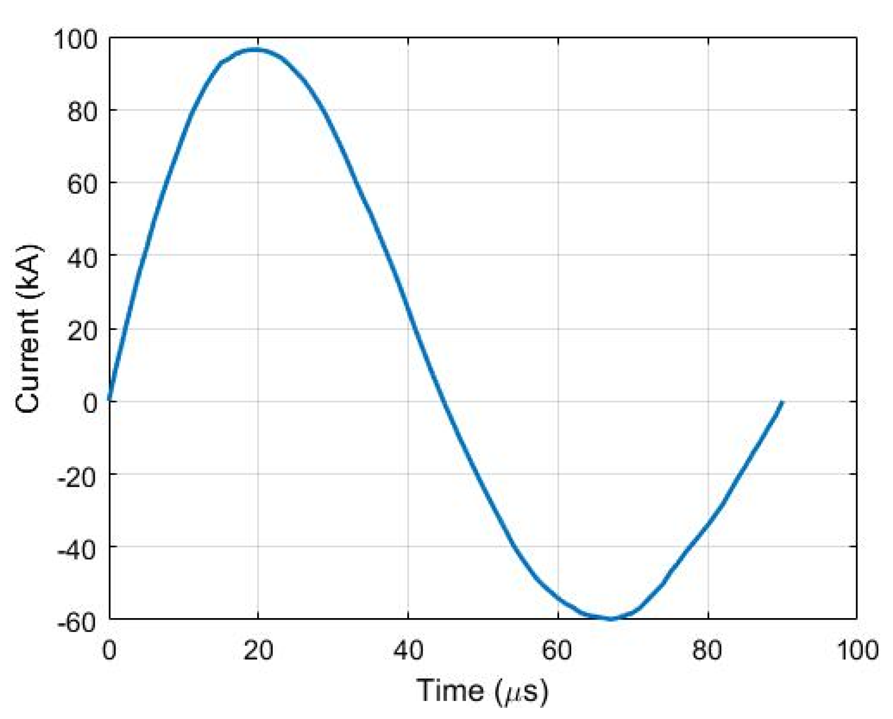
1]. In the EMF process, a large amount of energy on the order of tens of kilojoules is charged to a capacitor bank and then dissipates to a designed coil in the form of sinusoid damped current trace. A magnetic field is generated around the coil, and eddy currents are induced in the nearby conductive workpiece. Thus, the repulsive Lorentz forces are generated between the coil and workpiece, which is driven away and reaches a velocity of hundred meters per second in less than 1 ms. Due to the dynamic nature of this process, the workpiece formability can be improved. The other benefits of EMF include reduced material wrinkling and springback, high repeatability, improved dimensional accuracy, etc.
One of the main applications of EMF is magnetic pulse welding (MPW), a solid-state welding technology, which has rapidly developed in recent four decades. The most outstanding feature of solid-state welding is that there is no significant heat-affected zone (HAZ) generated after welding. Hence, a stronger weld seam than the parent materials is obtained, unlike the fusion welding processes, which usually degrades the joint strength and causes residual stress with consequent cracking and corrosion issues. MPW can also be used to weld dissimilar materials regardless of their differences in the melting point, thermal expansion, and thermal conductivity.
Interface morphology has been seen as one of the significant expressions of welding quality in impact welding processes. Previous researchers have published many works on the influences of process parameters on interface morphologies. Vivek et al. [2] studied interface wavelengths dependency on impact velocities and impact angles during vaporized foil actuator welding (VFAW) for the titanium and copper material system. The authors investigated the impact angle effects by pre-setting angled grooves on the target metals, and used various charging energies to drive the flyer, which impacts the target, at different impact velocities. Lee et al. [3] used a similar method to investigate process parameters for another material combination, aluminum, and steel, and conducted numerical analyses to support their experimental findings. In addition, Nassiri et al. [4] reported a robust numerical method to predict the interface morphology by investigating impact welding processes between titanium and copper alloys.
For tubular MPW processes, the effect of flyer kinetics was proposed for an Al6060 and C45 material combination in [5]. Raoelison et al. [6] used the same material for both flyer and target to investigate the welding conditions and predicted the interface morphology using the Eulerian method in ABAQUS. For the material combination of Aluminum and steel, Cui et al. [7] reported the dependence of high-quality welding of MPW on the wall thickness of the targets. A theoretical model based on Tresca yield criterion was also provided to verify the experimental findings. The quality of welding was also examined by peeling tests. The fatigue resistance and weld area of Al-Fe parts were investigated in [8]. The results indicated that the fracture occurred in the transition zone of the weld seam under a cyclic loading condition due to the relatively weaker strength and ductility of the materials in this area. Lueg-Althoff et al. [9] studied the relationship between the materials wall thicknesses and impact pressure for multiple material combinations during MPW. Dependency of the tension and torsion strengths of welded parts between Al3003 and steel for various discharge voltages during MPW was investigated by Yu et al. [10]. The metallurgical joint was only obtained within a specific voltage range, and the element content of the joint was analyzed. Ben-Artzy et al. [11] attributed the wave formation at the interface to the elastic stress waves caused by the impact during MPW process. The stress waves travelled through both metals away from the interface and reflected back off of the outer surfaces.
Although researchers experimentally and numerally investigated various process parameters’ effects on interface morphology and welding quality, the effects of material properties have drawn less attention. Thus, a more comprehensive understanding of the material combination effects during MPW is required. To investigate the interfacial morphology and parent material properties dependency during MPW, tubular Al1100, and two copper alloys, Cu101 and Cu110, as well as commercially pure Titanium (CP-Ti grade 2) joints were fabricated. The influence of two material properties, i.e., yield strength and density, was studied, and the interface morphology features were visually investigated. Results showed that both material properties affected the interface morphology. Numerical analyses were also conducted in LS-DYNA and validated the interface morphologies observed experimentally. These simulations show that the effect on the shear stresses in the material is the cause of the interface morphology variations we obtained.

2. Material Property Data

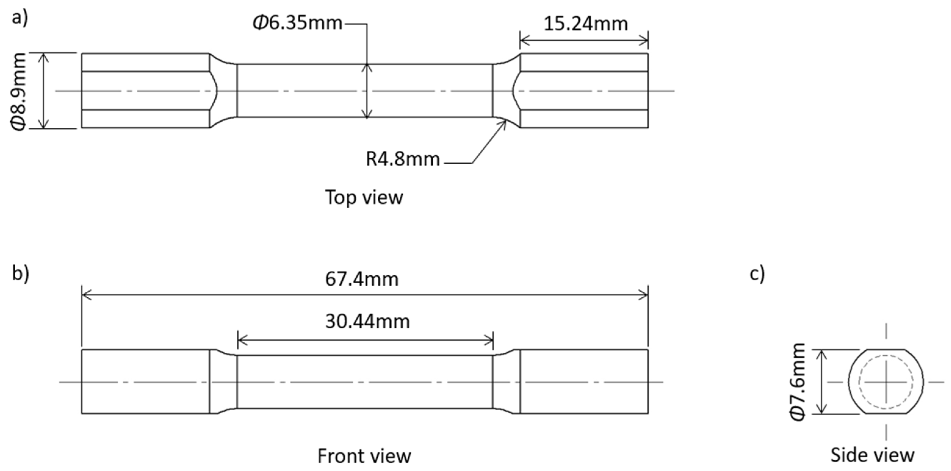
The material properties for the copper alloys and CP-Ti were tested on an MTS landmark servo-hydraulic test machine with a force capacity of 250kN. The specimens for the tensile tests were manufactured according to ASTM E-8 standards [12]. 
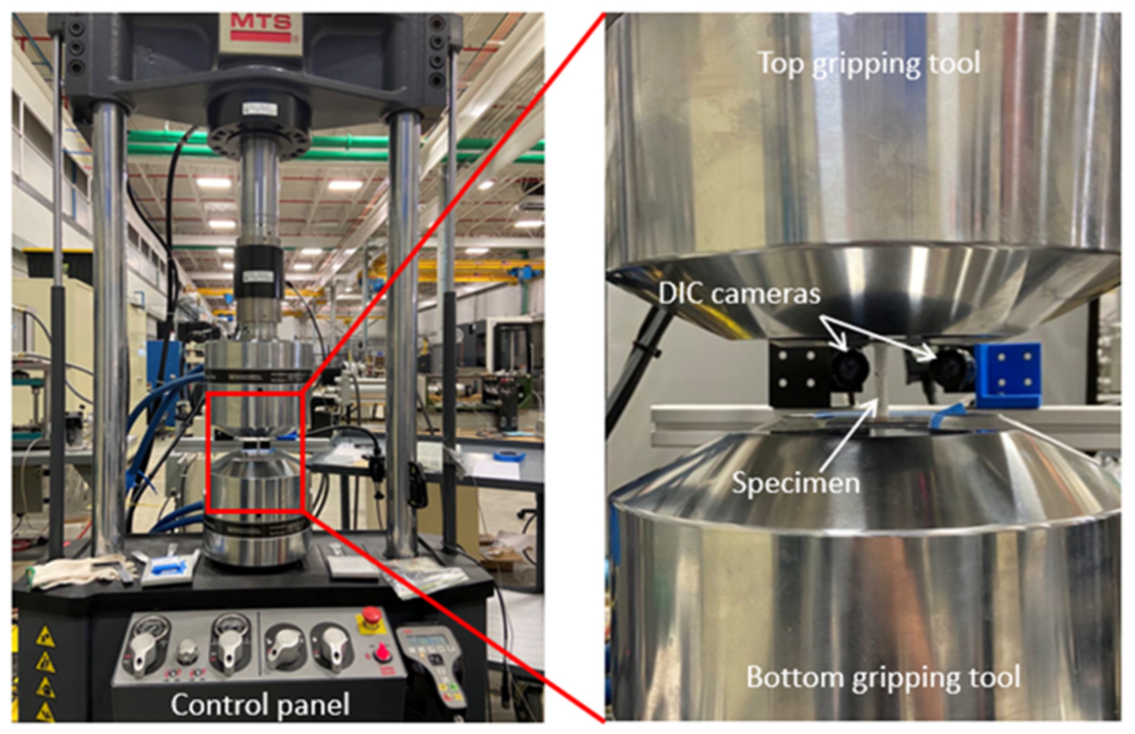
Figure 1 shows the dimensions of the specimens, and Figure 2 shows the tensile test setup on the MTS machine with a 3D Digital Image Correlation (DIC) system. DIC is an image analysis method that measures deformations of the specimen under load in three dimensions by using a speckle pattern and stereoscopic camera setup. The position of the speckle points on the specimen is used to calculate strain on the surface of the specimen based on the imaging parameters and orientation of the cameras [13]. For our tests, the DIC parameters used were a subset size of 19 pixels, a step size of 5 pixels, and a filter size of 5 pixels.
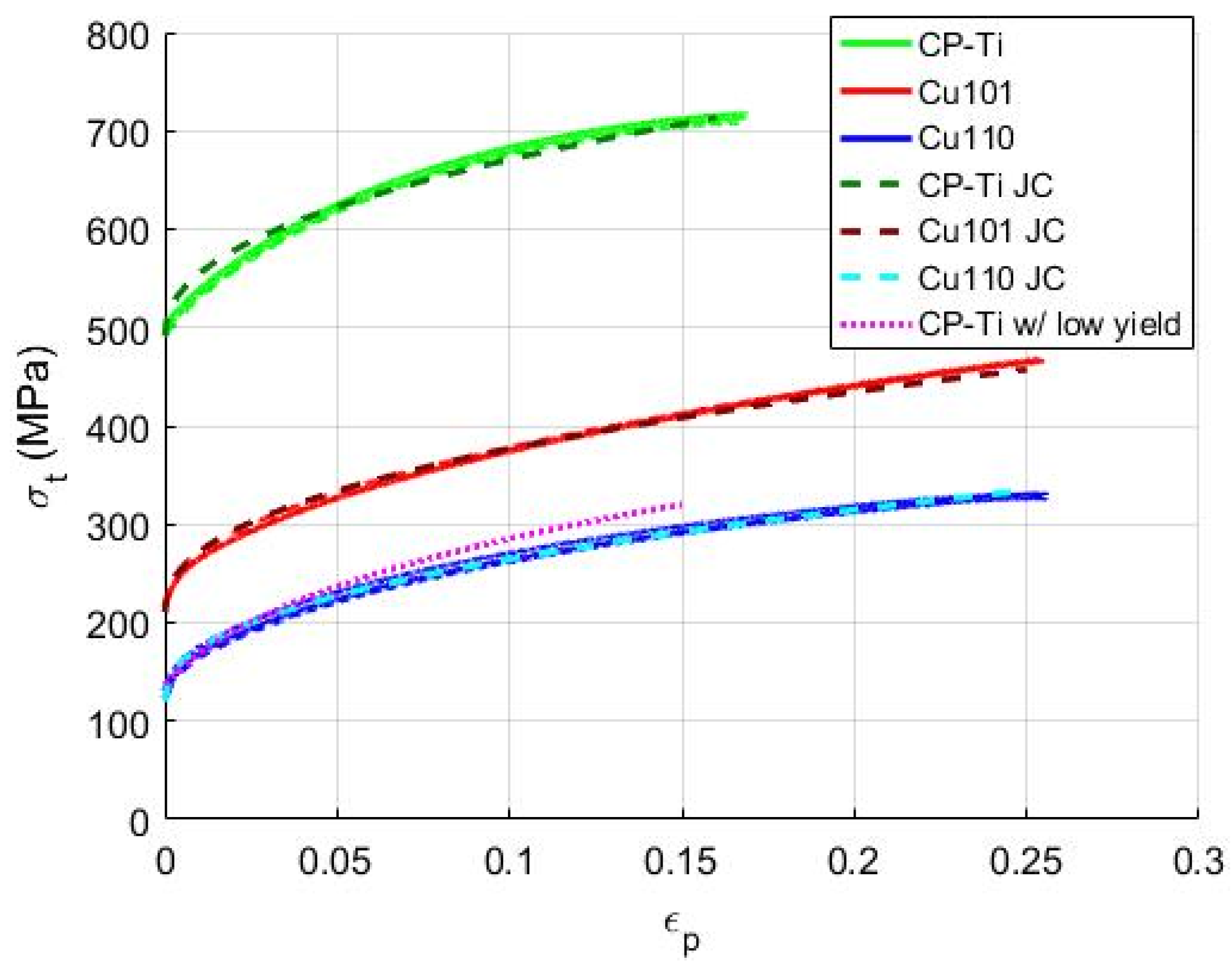
Figure 3 shows the flow curves of Cu101, Cu110, and CP-Ti that were used in the MPW experiments. All three materials were heat-treated before being used in tensile tests and MPW. Table 1 shows the heat treatment information for the copper alloys and CP-Ti. As shown in Figure 3, the yield strengths of Cu101, Cu110, and CP-Ti, determined by the 0.2% offset method, were clearly different, and better material formability was also shown for copper alloys compared to CP-Ti that had a lower material density. The chemical composition of copper alloys and CP-Ti are given in Table 2 and Table 3, respectively.
Three uniaxial tension specimens for each material were tested to verify the repeatability of the material properties. These results were plotted on top of each other in the same color but different line types in Figure 3. The dashed line with a different color on each material flow curve represented the fitted Johnson–Cook material model. Finally, the magenta dotted line was fictitious CP-Ti with the yield strength of Cu110, which was used in the simulations to investigate the yield strength effect for CP-Ti. The Johnson–Cook [14] material model parameters are given in Table 4.

2.1. Yield Strength

The first material property investigated was yield strength of target materials. Two heat-treated copper alloys, Cu101 and Cu110, were selected as the targets in this portion of the study, as they shared similar properties after heat treatment except for yield strength (see Figure 3). In addition, CP-Ti was also used as the target. To compare the interface of Al1100 & CP-Ti, a fictitious CP-Ti with low yield strength was used in numerical analyses.

2.2. Density

The effect of target material density on the interface morphology was also investigated. In this case, Cu110 was used as the target. A fictitious material with the same material properties of Cu110 except density was also used as a comparison in simulations.

3. Experimental Setup and Results

The experimental tests were conducted on a Maxwell Magneform JA7000 machine with a maximum energy capacity of 12 kJ. Other characteristics of the machine are given in 
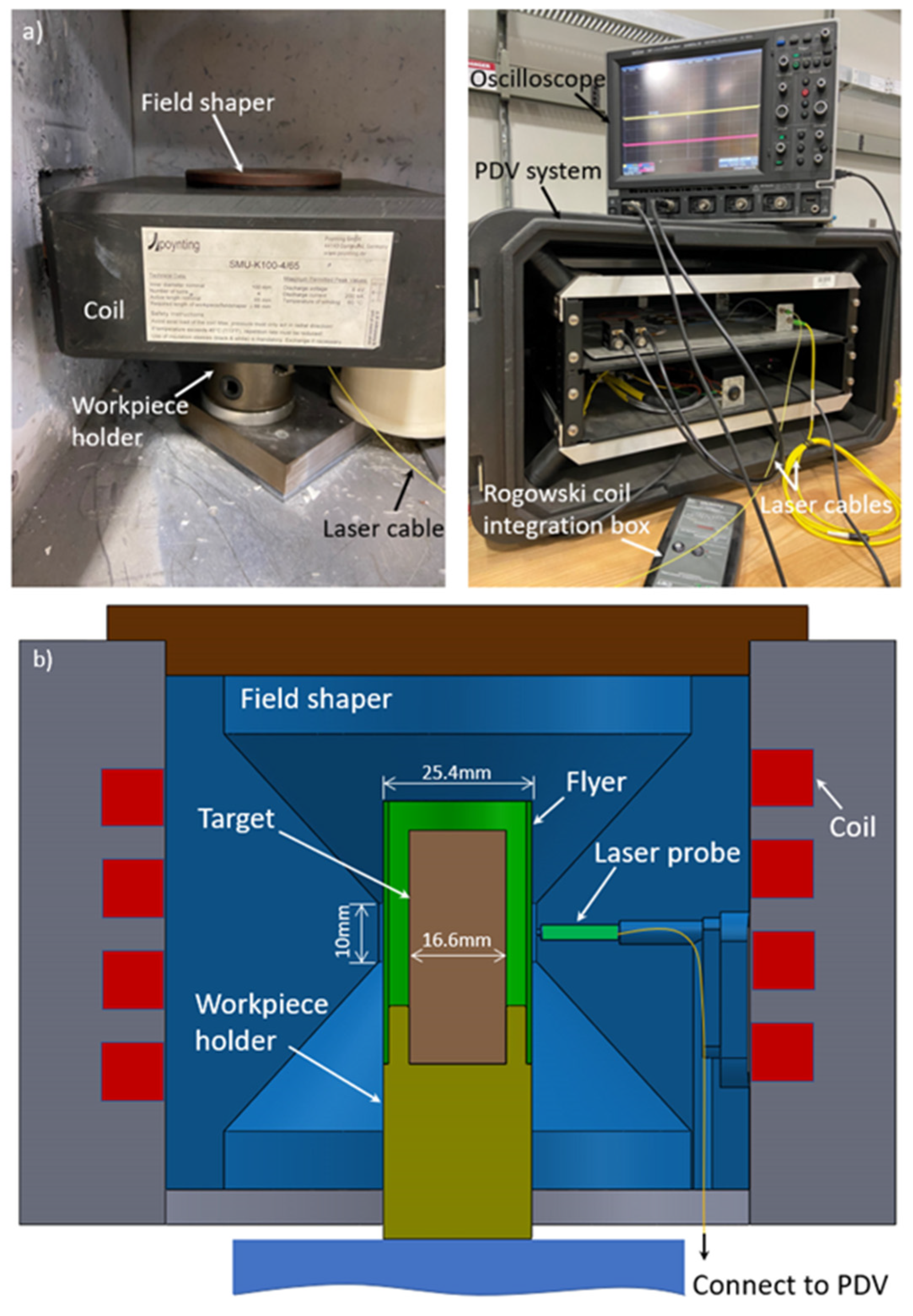
Table 5. A four-turn spiral coil was used in this study, along with a field shaper to concentrate the magnetic field generated (see Figure 4). Since the inner surface of the field shaper was much smaller than the outer surface, the magnetic pressure was concentrated in the radial direction and uniformly distributed along the circumferential direction [18]. The axial length of the pressure concentration zone of the field shaper was 10 mm and the inner diameter was 25.4 mm. The primary currents were measured by a Powertek CWT 3000B Rogowski coil, and impact velocities were measured by a PDV system. The PDV laser signal was focused on the outer surface of the flyer. A Doppler-shifted light was produced by the moving surface of the flyer during MPW, then combined with the incident light signal to produce a beat frequency, which is proportional to the velocity of the moving surface [19]. A small hole was drilled into the field shaper to provide a line of sight for the PDV laser probe (see Figure 4b). The outputs of the laser detector and Rogowski coil were recorded by a LeCroy WaveSurfer WS64MXS-B oscilloscope. A workpiece holder was used to keep both the flyer and target in position and concentric to each other.
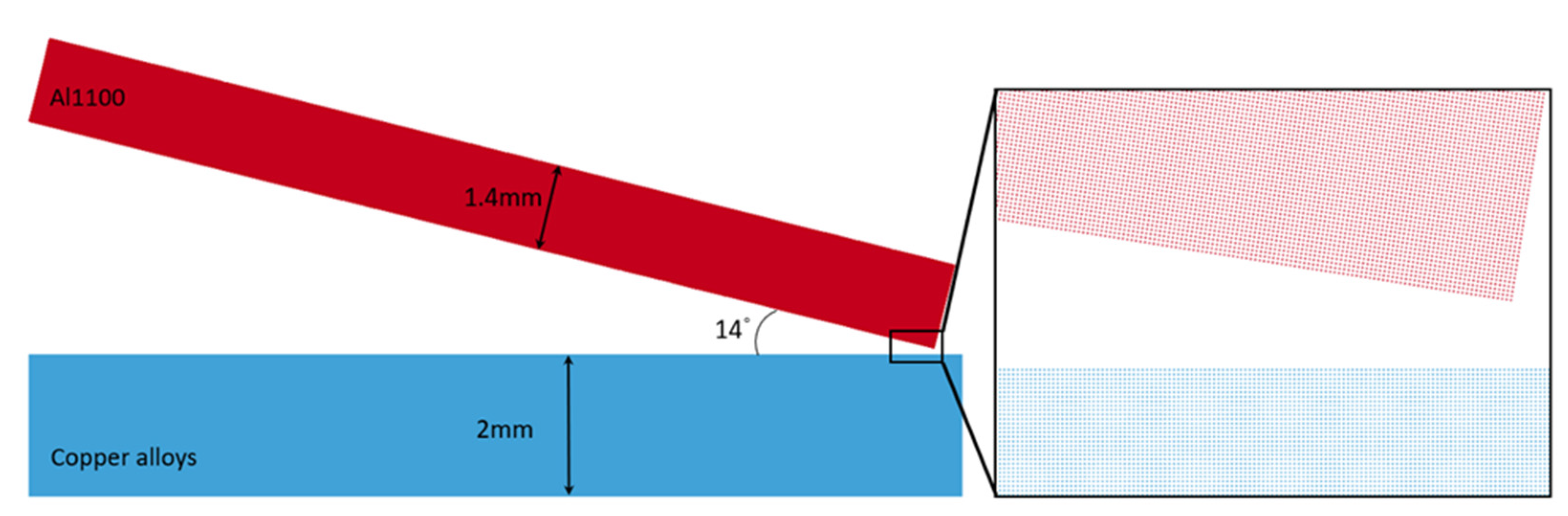
To investigate the effect of a single material property on the interface morphology, process parameters were kept unchanged. The targets were impacted by the same flyer material Al1100, at the same impact velocity of 315 m/s (see Figure 5). The error bars in Figure 5 represent the highest and lowest values measured for the nine tests conducted. The gap distance was 3.4 mm, the outer diameter of the flyer was 25.4 mm, the wall thickness was 1.4 mm. The targets were solid shafts with a 15.9 mm diameter.
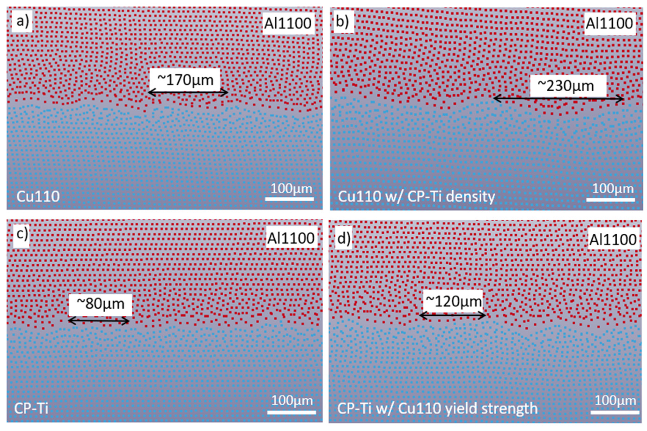
Figure 6 shows the interface morphologies after MPW at an energy level of 4.2 kJ. A flat interface was obtained between Al1100 and Cu101, while a regular wave occurred between Al1100 and Cu110 (see Figure 6a,b). As shown in Figure 3, the yield strengths of these two annealed copper alloys were clearly different, i.e., 220 MPa versus 135 MPa for Cu101 and Cu110, respectively. At the same time, the other material properties such as Young’s modulus, density, and work hardening behavior, were comparable. For this material combination, the target with a lower yield strength resulted in a joint with a wavy interface, while the target with a higher yield strength led to a flat interface.
Figure 6c shows the interface between Al1100 and CP-Ti. According to the data in Figure 3, CP-Ti has the highest yield strength; however, an irregular wave interface with a small wavelength was obtained due to the differences in material ductility (see Figure 3) and density, as CP-Ti had a lower density of 4510 kg/m3 compared to 8910 kg/m3 for the copper alloys. Figure 6d–f are numerical results, which are in good agreement with each experimental observation, respectively. The next section will provide details related to these numerical simulations.

4. Numerical Simulations

4.1. Electromagnetic Forming

Finite element analyses of EMF and MPW processes were conducted using LS-DYNA, as their electromagnetism (EM) model is capable of capturing the effects of tube deformation on the magnetic fields in proximity to the coil. Process parameters in the numerical simulations were the same as in experimental tests, i.e., the dimensions and geometries of the coil, field shaper, and workpieces were defined as those in the experimental tests. Figure 7 shows the EMF model set up in LS-PREPOST. The material properties of the tube were described by the Johnson–Cook material model:
σ ¯ = ( A + B ε p n ) ( 1 + C l n ε p ˙ ε 0 ˙ ) ( 1 ( T T r T m T r ) m )
where σ ¯ is the flow stress, εp is the plastic strain, and ε p ˙ the effective plastic strain rate, ε p 0 ˙ is the reference plastic strain rate, m, n, A, B, and C are the material constants, and Tm and Tr are the melting and room temperature, respectively. The coil and field shaper were modeled as rigid bodies. The current traces used in the simulations were measured by the Rogowski coil. The model contained 70,000 elements in total. A finer mesh was defined in regions close to surfaces to capture the skin depth effects. Table 6 gives the material properties used in these simulations. Electrical conductivities were only defined for the field shaper and flyer, which were Al1100 and copper, respectively.
First, EMF simulations were conducted to determine the desired gap between the flyer and target to achieve the peak velocity at impact during MPW and the corresponding charging energy level. Figure 8 shows the comparisons of experimental and numerical velocities and displacements of the flyer. The blue lines represent the peak velocities corresponding to the left Y-axis. The right Y-axis shows the displacements at peak velocities and corresponds to the red lines in the figure. To investigate the effect of yield strength on the interface, a 4.2 kJ charging energy was chosen, where the flyer travelled approximately 3.4 mm and reached a peak velocity of 315 m/s. While the velocity is still increasing in Figure 8, the displacement is leveling off at 4.2 kJ. In addition, wrinkling was occurring in the tube at higher charge energies. Therefore, higher charge energies were not investigated. The current trace for a 4.2 kJ energy discharge is shown in Figure 9, with only the first cycle included. Based on the displacement data in Figure 5, the deformation is clearly finished by 90 μs.

4.2. Impact Welding

To accurately capture the wavy morphology at the interface, numerical simulations for impact welding were also conducted in LS-DYNA using the smoothed particle hydrodynamics (SPH) method, which is able to analyze the problem of large local deformations, which occur at the interface during MPW. A 2D, axisymmetric SPH analysis in LS-DYNA was used to reduce the computational time. A simplified model was set up in LS-PREPOST for this study (see Figure 10). A flat interface is created in the very center of the flyer and base material interface, where the initially parallel materials first collide during impact welding. As the process progresses, an impact angle is created away from the center of the process, and the wavy interface occurred. In the numerical model, only the portion of the process where the wavy interface occurred was simulated. Thus, the angle between the flyer and target was fixed at 14° in the model based on [20]. The length for both target and flyer was 10 mm. The thicknesses were 1.4 mm and 2 mm for the flyer and target, respectively. The impact velocity used in the model was obtained from experimental tests by PDV system, i.e., 315 m/s. The SPH particle size was defined as 5 µm to capture the interface morphology.
Numerical results of the effect of target yield strengths are shown in Figure 6d,e. Comparable interface morphologies were observed both in experimental and numerical results. A relatively flat interface occurred when using Cu101 as the target, while the wavy interface was obtained in the case of using Cu110, which has a lower yield strength.
To investigate the density effect for Cu110 and yield strength effect for CP-Ti, two fictitious materials were created in the numerical simulations. The first material shared the material properties of Cu110, but the density was defined as 4510 kg/m3, i.e., that of CP-Ti, and the second shared the material properties of CP-Ti except for the yield strength, which was set to be the same as Cu110 (see Figure 3). Figure 11a,b shows the interface morphology comparison of Al1100 & Cu110 and the fictitious Cu110 with the CP-Ti density. Figure 11c,d shows the interface morphology comparison of Al1100 & CP-Ti and the fictitious CP-Ti with the Cu110 yield strength. A similar trend occurred for both of these results, i.e., the target with lower density (Figure 11b) and the target with a lower yield strength (Figure 11d) led to an interface with a larger wavelength. Figure 11b,d is the interfaces for the two fictitious target materials with the same density (4510 kg/m3) and yield strength (Cu110 yield strength), but the interfaces with different wavelengths were obtained. This was caused by the dissimilarity in material hardening behavior, various equations of state (e.g., speed of sound) for the Johnson–Cook material model, and slight differences in the Young’s moduli of these two materials.

5. Discussion

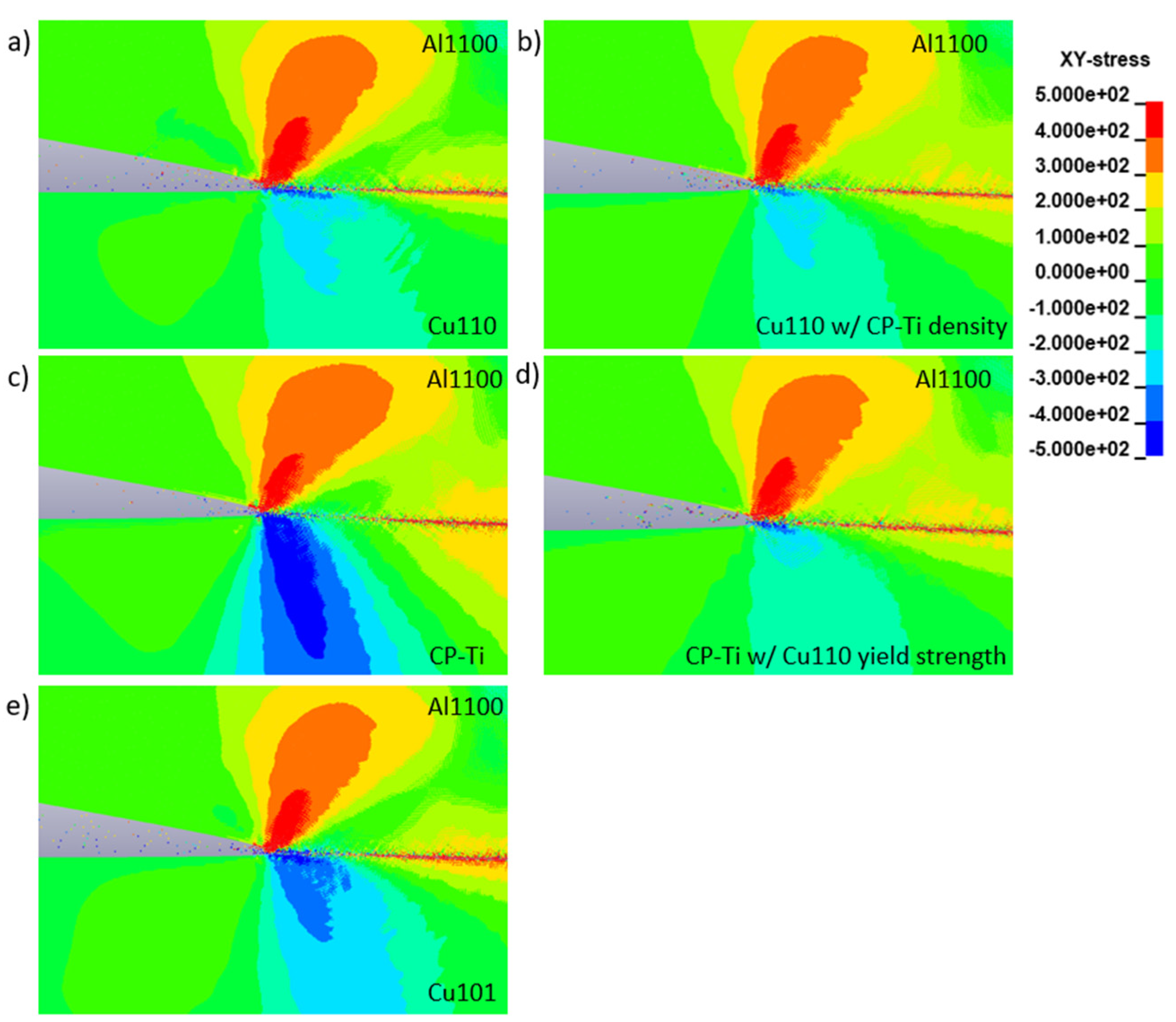
Process parameters such as shear velocity, shear stress, and contact pressure were investigated in the numerical simulations to understand why lower yield strength and lower density resulted in differences in the wavy interface for these material combinations during MPW. Figure 12 shows the shear stresses at the same time increment for the material combinations of Al1100 & Cu110, Al1100 & Cu101, Al1100 & CP-Ti, Al1100 & CP-Ti with Cu110 yield strength, and Al1100 & Cu110 with CP-Ti density. Past research has shown that the shear stress is one of the reasons for the intense local deformation in proximity to the collision point, which leads to a wavy interface [21]. As shown in Figure 12, the shear stress concentrated more on the target side in proximity of the collision point when the target yield strength was lower, i.e., Figure 12a,b,d. Thus, a wavy interface was easier to create as the local deformation near the collision point occurred due to the larger shear stress difference between the region near the collision point and the other areas of the target. Despite having the largest shear stress in the target material, a wavy interface was also observed in CP-Ti, e.g., compared to Cu101, due to the other material properties that affect this behavior. Furthermore, based on the theory of Kelvin-Helmholtz instability, the interfacial wavelength is proportional to the depth of the plastically deformed layer. Specifically, the target with lower yield strength was more easily deformed at the interface under the same impact velocity. Thus, in this study, the change in the interfacial morphology was clearly associated with the target yield strength.
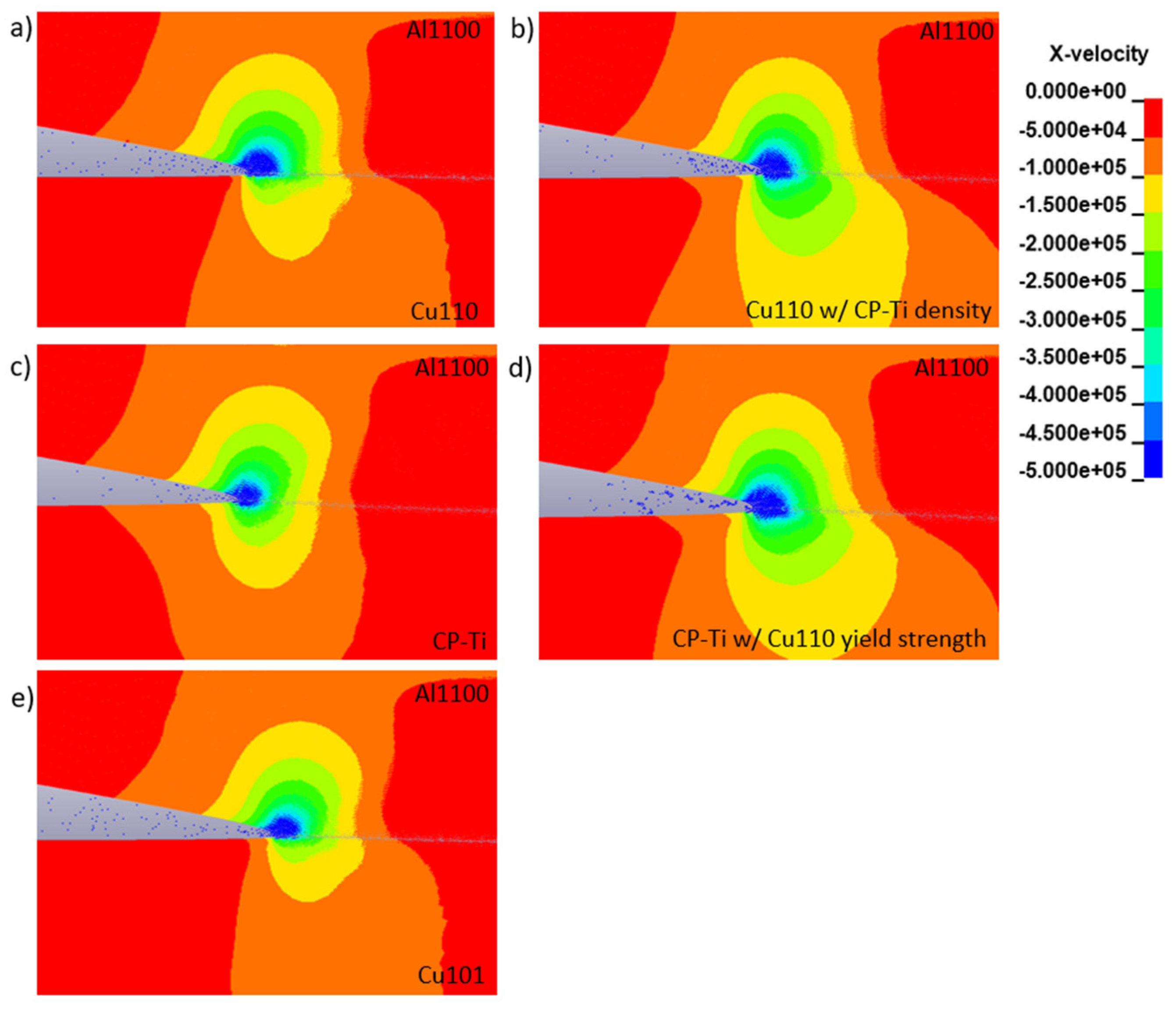
Figure 13 shows the shear velocities at the interfaces. For each case, there is not a clear difference in shear velocity, which is a parameter that is mainly affected by the impact velocity. Note that the impact velocity was the same in each experiment and numerical simulation in this study. Therefore, there is no effect of shear velocity on the wavy interface observed. In 
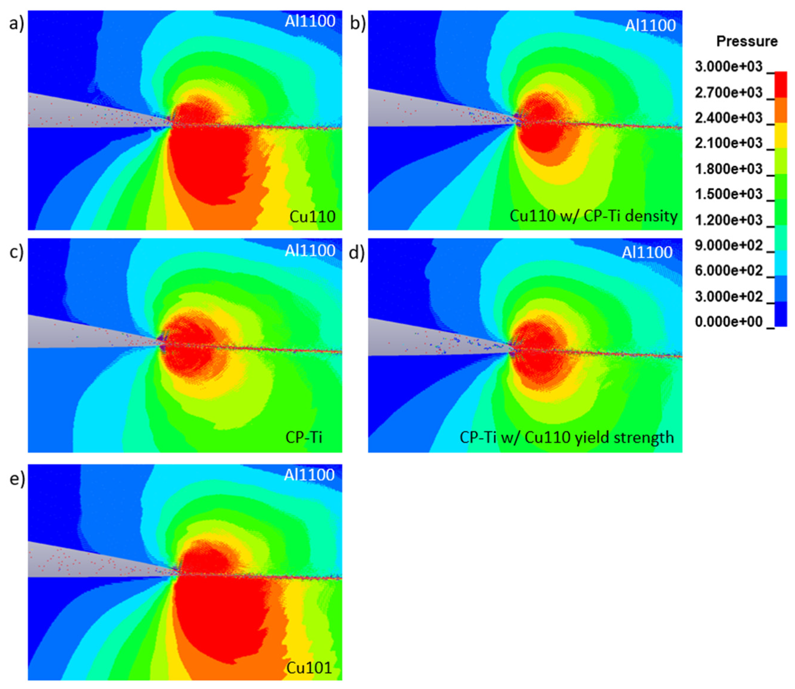
Figure 14, the contact pressure is shown for the various cases investigated. The images for the copper alloys with the corresponding appropriate densities, i.e., Figure 14a for Cu110 and Figure 14e for Cu101, show higher contact pressure values due to their higher densities compared to the plots with CP-Ti densities, i.e., Figure 14b–d. The contact pressure is known to be affected by the speed of sound in the material (with CP-Ti being 15% larger than that of copper alloys, i.e., 4140 m/s versus 3570 m/s, respectively) and density [4]. Thus, the variations in the wavy interface do not correlate to the contact pressure. The fact that shear velocity and contact pressure, i.e., Figure 13 and Figure 14 respectively, do not show an effect on the wavy interface morphology is a noteworthy finding.

6. Conclusions

In this research, results show the effect of material properties on interface morphologies during MPW. Numerical analyses were in good agreement with the experimental observations, i.e., interface morphologies, thus allowing for process parameters that cannot be physically measured to be investigated. Both experimental measurements and numerical predictions for velocity and displacement determined the gap distance and energy level to use for each case. For the material combination of Al1100 and annealed copper alloys, a lower yield strength of the target led to a joint with a wavy interface, while a flat interface was obtained for the target with a higher yield point. Using CP-Ti, i.e., a target with lower density and higher yield strength, an interface with smaller waves was obtained in the experiments and numerical simulations. Two fictitious materials were also modeled in simulations to further assess the effects of varying process parameters. Numerical results using CP-Ti material parameters, except for the yield strength of Cu110, as the target and Cu110 material parameters, except for the density of CP-Ti, were compared to that of the actual CP-Ti and Cu110 materials, respectively. Using both the fictitious materials (CP-Ti with Cu110 yield strength, and Cu110 with CP-Ti density) resulted in a wavy interface with larger wavelengths than their comparison partners. These results provide insight into the material properties that affect the wavy interface during MPW.

Author Contributions

Conceptualization, S.Z. and B.L.K.; methodology, S.Z. and B.L.K.; software, S.Z.; validation, S.Z. and B.L.K.; formal analysis, S.Z. and B.L.K.; investigation, S.Z.; resources, S.Z. and B.L.K.; data curation, S.Z.; writing—original draft preparation, S.Z.; writing—review and editing, S.Z. and B.L.K.; visualization, S.Z.; supervision, B.L.K.; project administration, B.L.K.; funding acquisition, B.L.K. Both authors have read and agreed to the published version of the manuscript.

Funding

The research was funded by the U.S. National Science Foundation, grant number CMII-1537471.

Data Availability Statement

The data presented in this study are available on request from the corresponding author.

Conflicts of Interest

The authors declare no conflict of interest.

References

  1. Shribman, V. Magnetic Pulse Welding for Dissimilar and Similar Materials. In Proceedings of the 3rd International Conference on High Speed Forming, Dortmund, Germany, 11–12 March 2008; p. 10. [Google Scholar]
  2. Vivek, A.; Liu, B.C.; Hansen, S.R.; Daehn, G.S. Accessing Collision Welding Process Window for Titanium/Copper Welds with Vaporizing Foil Actuators and Grooved Targets. J. Mater. Process. Technol. 2014, 214, 1583–1589. [Google Scholar] [CrossRef]
  3. Lee, T.; Zhang, S.; Vivek, A.; Kinsey, B.; Daehn, G. Flyer Thickness Effect in the Impact Welding of Aluminum to Steel. J. Manuf. Sci. Eng. 2018, 140, 121002. [Google Scholar] [CrossRef]
  4. Nassiri, A.; Vivek, A.; Abke, T.; Liu, B.; Lee, T.; Daehn, G. Depiction of Interfacial Morphology in Impact Welded Ti/Cu Bimetallic Systems Using Smoothed Particle Hydrodynamics. Appl. Phys. Lett. 2017, 110, 231601. [Google Scholar] [CrossRef]
  5. Lueg-Althoff, J.; Bellmann, J.; Gies, S.; Schulze, S.; Tekkaya, A.E.; Beyer, E. Influence of the Flyer Kinetics on Magnetic Pulse Welding of Tubes. J. Mater. Process. Technol. 2018, 262, 189–203. [Google Scholar] [CrossRef]
  6. Raoelison, R.N.; Buiron, N.; Rachik, M.; Haye, D.; Franz, G. Efficient Welding Conditions in Magnetic Pulse Welding Process. J. Manuf. Process. 2012, 14, 372–377. [Google Scholar] [CrossRef]
  7. Cui, J.; Sun, G.; Xu, J.; Xu, Z.; Huang, X.; Li, G. A Study on the Critical Wall Thickness of the Inner Tube for Magnetic Pulse Welding of Tubular Al–Fe Parts. J. Mater. Process. Technol. 2016, 227, 138–146. [Google Scholar] [CrossRef]
  8. Geng, H.; Sun, L.; Li, G.; Cui, J.; Huang, L.; Xu, Z. Fatigue Fracture Properties of Magnetic Pulse Welded Dissimilar Al-Fe Lap Joints. Int. J. Fatigue 2019, 121, 146–154. [Google Scholar] [CrossRef]
  9. Lueg-Althoff, J.; Bellmann, J.; Hahn, M.; Schulze, S.; Gies, S.; Tekkaya, A.E.; Beyer, E. Joining Dissimilar Thin-Walled Tubes by Magnetic Pulse Welding. J. Mater. Process. Technol. 2020, 279, 116562. [Google Scholar] [CrossRef]
  10. Yu, H.; Xu, Z.; Fan, Z.; Zhao, Z.; Li, C. Mechanical Property and Microstructure of Aluminum Alloy-Steel Tubes Joint by Magnetic Pulse Welding. Mater. Sci. Eng. A 2013, 561, 259–265. [Google Scholar] [CrossRef]
  11. Ben-Artzy, A.; Stern, A.; Frage, N.; Shribman, V.; Sadot, O. Wave Formation Mechanism in Magnetic Pulse Welding. Int. J. Impact Eng. 2010, 37, 397–404. [Google Scholar] [CrossRef]
  12. E28 Committee. Test Methods for Tension Testing of Metallic Materials; ASTM International: West Conshohocken, PA, USA, 2011. [Google Scholar]
  13. Michael, A.M.A.; Orteu, J.-J.; Schreier, H.W. Digital Image Correlation (DIC). In Image Correlation for Shape, Motion and Deformation Measurements: Basic Concepts, Theory and Applications; Schreier, H., Orteu, J.-J., Sutton, M.A., Eds.; Springer: Boston, MA, USA, 2009; pp. 1–37. [Google Scholar]
  14. Johnson, G.; Cook, W. A Constitutive Model and Data for Materials Subjected to Large Strains, High Strain Rates, and High Temperatures–ScienceOpen. In Proceedings of the 7th International Symposium on Ballistics, Miami, FL, USA, 19–21 April 1983; pp. 541–547. [Google Scholar]
  15. Iwamoto, T.; Yokoyama, T. Effects of Radial Inertia and End Friction in Specimen Geometry in Split Hopkinson Pressure Bar Tests: A Computational Study. Mech. Mater. 2012, 51, 97–109. [Google Scholar] [CrossRef] [Green Version]
  16. Meyers, M.A.; Andrade, U.R.; Chokshi, A.H. The Effect of Grain Size on the High-Strain, High-Strain-Rate Behavior of Copper. Metall. Mater. Trans. A 1995, 26, 2881–2893. [Google Scholar] [CrossRef]
  17. Magargee, J.; Morestin, F.; Cao, J. Characterization of Flow Stress for Commercially Pure Titanium Subjected to Electrically Assisted Deformation. J. Eng. Mater. Technol. 2013, 135, 041003. [Google Scholar] [CrossRef]
  18. Yu, H.; Li, C.; Zhao, Z.; Li, Z. Effect of Field Shaper on Magnetic Pressure in Electromagnetic Forming. J. Mater. Process. Technol. 2005, 168, 245–249. [Google Scholar] [CrossRef]
  19. Banik, K.; Daehn, G.S.; Fenton, G.K.; Golowin, S.; Henchi, I.; Johnson, J.R.; Eplattenier, P.L.; Taber, G.; Vivek, A.; Zhang, Y. Coupling Experiment and Simulation in Electromagnetic Forming Using Photon Doppler Velocimetry. In Proceedings of the 3rd International Conference on High Speed Forming, Dortmund, Germany, 11–12 March 2008. [Google Scholar]
  20. Lee, T.; Zhang, S.; Vivek, A.; Daehn, G.; Kinsey, B. Wave Formation in Impact Welding: Study of the Cu–Ti System. CIRP Ann. 2019, 68, 261–264. [Google Scholar] [CrossRef]
  21. Zhang, S.; Kinsey, B. Numerical Investigation of Impact Welding by Eulerian and Smoothed Particle Hydrodynamic Methods. In Proceedings of the 13th International Conference on Numerical Methods in Industrial Forming Processes, Portsmouth, NH, USA, 23–27 June 2019. [Google Scholar]
Figure 1. Dimensions of tensile test specimen (a) top, (b) front, and (c) side.
Jmmp 05 00064 g001
Figure 2. Tensile tests on MTS machine with DIC system.
Jmmp 05 00064 g002
Figure 3. Tensile test results of Cu11 Cu101, and CP-Ti and Johnson-Cook models.
Jmmp 05 00064 g003
Figure 4. (a) Experimental setup and PDV system, (b) schematic of coil, field shaper, and workpieces.
Jmmp 05 00064 g004
Figure 5. Velocity measured by PDV system.
Jmmp 05 00064 g005
Figure 6. Interface morphology difference, experiments: (a) Al1100 & Cu110, (b) Al1100 & Cu101, (c) Al1100 & CP-Ti, SPH: (d) Al1100 & Cu110, (e) Al1100 & Cu101, (f) Al1100 & CP-Ti.
Jmmp 05 00064 g006
Figure 7. EMF model defined in LS-PREPOST (a) 3D model, (b) cross-section.
Jmmp 05 00064 g007
Figure 8. Peak velocities and corresponding displacements.
Jmmp 05 00064 g008
Figure 9. Current trace for 4.2 kJ charging energy.
Jmmp 05 00064 g009
Figure 10. SPH model defined in LS-PREPOST.
Jmmp 05 00064 g010
Figure 11. Interface morphologies of Al1100 & (a) Cu110, (b) fictitious Cu110 with the density of CP-Ti, (c) CP-Ti, and (d) fictitious CP-Ti with the yield strength of Cu110.
Jmmp 05 00064 g011
Figure 12. Shear stresses at the interfaces for Al1100 & (a) Cu110, (b) fictitious Cu110 with the density of CP-Ti, (c) CP-Ti, (d) fictitious CP-Ti with the yield strength of Cu110, and (e) Cu101.
Jmmp 05 00064 g012
Figure 13. Shear velocities at the interfaces for Al1100 & (a) Cu110, (b) fictitious Cu110 with the density of CP-Ti, (c) CP-Ti, (d) fictitious CP-Ti with the yield strength of Cu110, and (e) Cu101.
Jmmp 05 00064 g013
Figure 14. Contact pressures at the interfaces for Al1100 & (a) Cu110, (b) fictitious Cu110 with the density of CP-Ti, (c) CP-Ti, (d) fictitious CP-Ti with the yield strength of Cu110, and (e) Cu101.
Jmmp 05 00064 g014
Table 1. Heat treatment information of each material.
MaterialTemperature (F)Duration (h)Cooling
Cu1106502Water
Cu1016502Water
CP-Ti12002Air
Table 2. Chemical composition of copper alloys, % by weight.
MaterialCopperOxygen
Cu11099.90.04
Cu10199.90.0005
Table 3. Chemical composition of CP-Ti, % by weight.
MaterialTitaniumOxygenCarbonNitrogenIronHydrogen
CP-Ti99.310.250.10.030.30.015
Table 4. Johnson–Cook material model parameters, Al1100 [15], Copper alloys [16], CP-Ti [17].
MaterialA (MPa)B (MPa)nCmTm (K)
Al1100173240.250.20.7933
Cu1101173890.430.0251.091356
Cu1012114480.430.0251.091356
CP-Ti4915070.450.01940.581941
Table 5. Characteristics of the pulse generator.
MachineMaximal Charging Energy (kJ)Maximal Charging Voltage (kV)Capacitance (µF)Internal Inductance (nH)Internal Resistance (mΩ)
Maxwell Magneform JA7000128.165360724.38
Table 6. Selected material properties used in the simulations.
MaterialsYoung’s Modulus (GPa)Density (kg/m3)Electrical Conductivity (S/m)
Al11007527003.77 × 107
Copper12089105.96 × 107
CP-Ti1164510-
Publisher’s Note: MDPI stays neutral with regard to jurisdictional claims in published maps and institutional affiliations.

