
Tensile Performance of 3D-Printed Continuous Fiber-Reinforced Nylon Composites


1
Department of Mechanical Engineering and Center for Manufacturing Research, College of Engineering, Tennessee Tech University, Cookeville, TN 38505, USA
2
Department of Manufacturing and Engineering Technology, College of Engineering, Tennessee Tech University, Cookeville, TN 38505, USA
*
Author to whom correspondence should be addressed.
J. Manuf. Mater. Process. 2021, 5(3), 68; https://0-doi-org.brum.beds.ac.uk/10.3390/jmmp5030068
Submission received: 7 June 2021
/
Revised: 21 June 2021
/
Accepted: 24 June 2021
/
Published: 29 June 2021
Abstract
:Fused Filament Fabrication (FFF) is a promising technology for production of fiber-reinforced composite parts with complex geometries. Continuous Fiber Reinforced Additively Manufactured (CFRAM) parts are becoming more prominent due to their mechanical performance, light weight, and recyclability. CFRAM components are lighter, yet they are strong materials with a wide range of potential applications in the automotive industry, aerospace, medical tools, and sports goods. The wide range of applications of these novel materials justifies the need to study their properties. Tensile is one of the most important tests to evaluate the mechanical performance of CFRAM parts. In this paper, a comprehensive study is conducted on tensile properties of CFRAM components. The composite parts are printed using a dual nozzle 3D printing machine and their tensile performance is investigated. Furthermore, the effect of fiber type, fiber content, infill density, infill pattern, and layer thickness on tensile properties was studied. Nylon was used as the matrix and Carbon fiber (CF), fiberglass (FG), and Kevlar were used as reinforcing agents. Microstructural analysis was conducted to investigate the fracture mechanism, internal morphology, interlayer adhesion, and the printing quality of specimens. Finally, a comparative study is conducted on the price and printing time of CFRAM parts. It is observed that fiber inclusion increases the tensile strength up to 2200%; moreover, increasing the fiber content improves the tensile performance of composite. The results obtained demonstrate that CF-reinforced parts have better performance compared to FG and Kevlar-reinforced components. The results show that CFRAM parts have potential to replace metals and conventional composites for engineering applications like the automobile industry.
1. Introduction
Additive Manufacturing (AM) technology has had a sharp growth rate in the recent decade [1,2,3,4]. In the right applications, AM delivers a combination of improved performance, complex geometries, and simplified fabrication. AM has several advantages compared to conventional manufacturing methods [5,6]. Some of the advantages are the easy process of parts with complicated geometries, low cost for rapid prototyping, low waste of materials, and a wide range of applications. Among all AM methods, the FFF technique is of particular interest because of its low cost and easy use [7].
Although the FFF technology is a growing field in AM, there are limitations that restrict the growth of this method [8,9]. First, the printing time of the process is much longer compared to conventional manufacturing methods. Second, polymer products lack the strength as a fully functional part. Due to the voids in the structure, mechanical properties of finished parts are not sufficient for engineering applications. Voids in the structures serve as stress concentration areas and reduce the mechanical performance of the part.
Still, most of the polymer products produced with FFF technology are used as prototypes, since polymer products are lack of performance in the range of engineering parts. Addition of fiber reinforcement in the polymer structure during the printing process is a solution to overcome this limitation. The motivation for this research is to improve the mechanical properties of additively manufactured polymers for engineering applications. The novelty of the paper is the study of tensile properties of continuous fiber-reinforced polymer composite components with a comprehensive investigation of the effect of major process parameters on tensile strength and elastic modulus. The results of this research increases the applicability of 3D-printed parts for industrial applications.
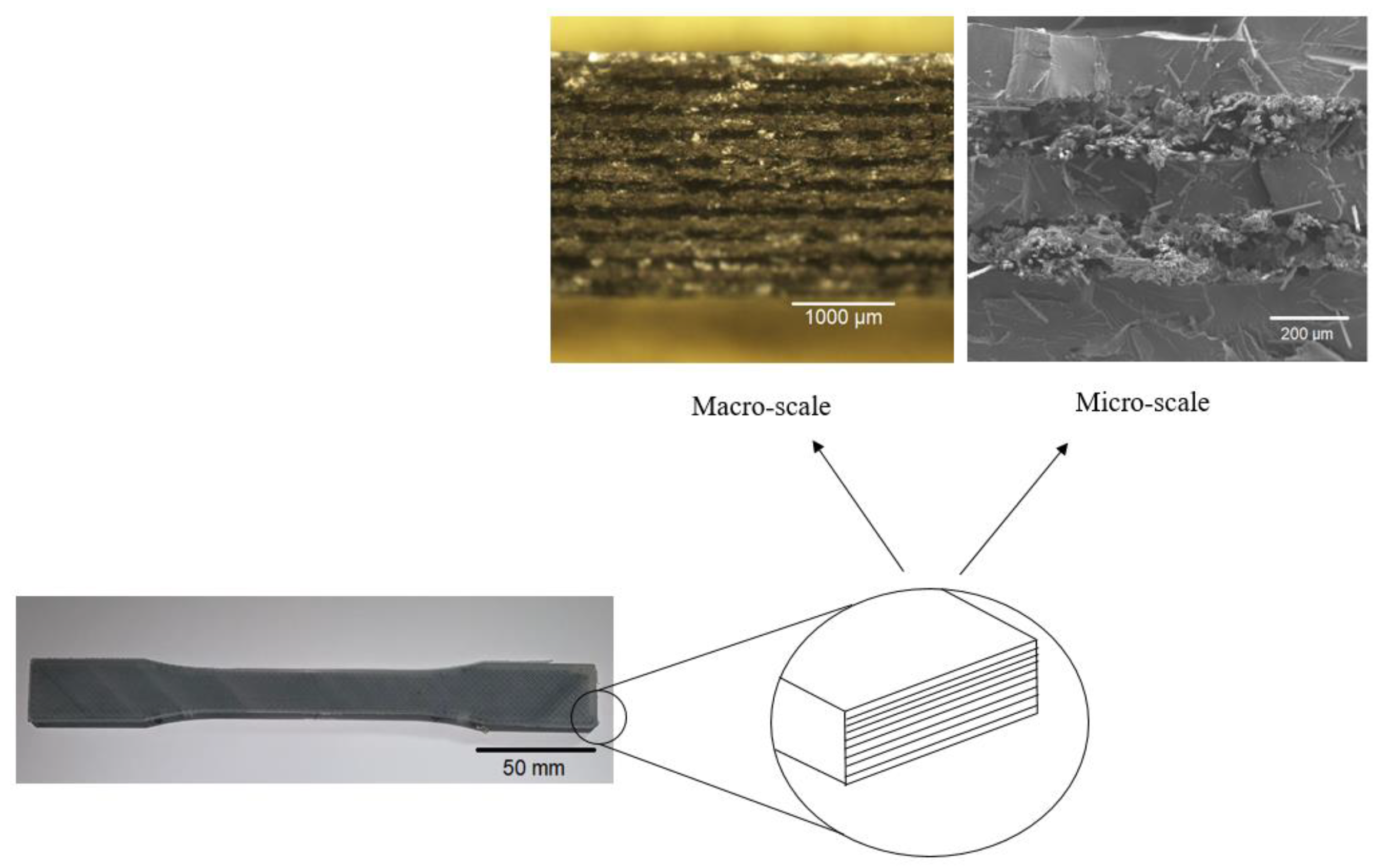
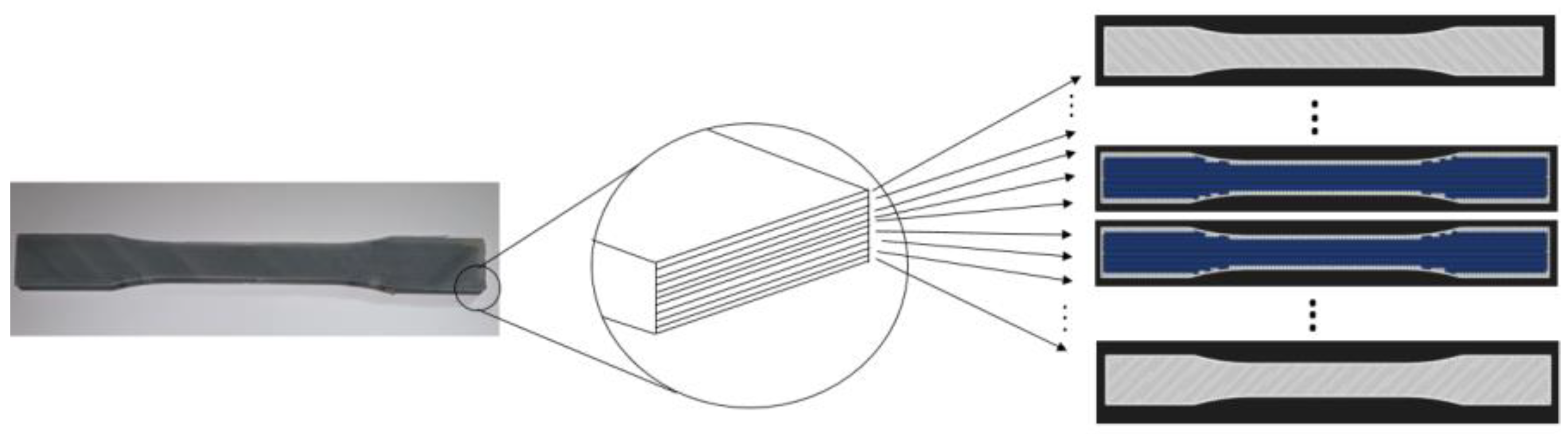
The materials used in the FFF process are thermoplastic polymers in a filament form. Different thermoplastic polymers can be used in the FFF process, including nylon, acrylonitrile butadiene styrene (ABS), polylactic acid (PLA), and polypropylene (PP). In the current research, continuous fiber is used as a reinforcing agent to improve the mechanical performance of polymer for engineering applications. In this method, a layered composite is produced using a dual-head printer with controlled layer numbers, fiber orientation, reinforcement type, etc. Figure 1 demonstrates the schematic representation of a CFRAM component and different layers on a macro and micro scale.
Cast iron, stainless steel, and aluminum are three conventional metals used for industrial applications. They have excellent performance, but their density is too high. Furthermore, their manufacturing process is expensive and time consuming. The compression molded reinforced polymer composites are used extensively for industrial applications due to the low weight, proper mechanical properties, easy process, and low price. During the process, high pressure in the range of 4–25 kg/cm2 is applied to the part, which eliminates almost all voids in the structure. The main drawback of this method is the need for molding, an operator, and heavy equipment like a press machine or an oven.
The CFRAM technology is exempt from molding and the complicated parts can be produced from computer models. Moreover, fiber amount, fiber type, orientation, and other properties can be customized easily according to the geometry of the part. The method also has some drawbacks, including lack of mechanical properties and production time. Due to the lack of applied pressure during the printing process, voids remain inside the structure, which these voids are considered as stress concentration areas.
The CFRAM method, due to the ease of use, high performance, precision, and low cost has attracted many attentions in various industries and research labs [10,11,12,13]. CFRAM offers a significant enhancement in mechanical properties compared to unreinforced and discontinuous fiber-reinforced parts [14]. In recent years, Markforged Company made a remarkable development in CFRAM technology by introducing desktop composite 3D Printers [15,16,17,18,19]. The printer uses a dual extrusion technique which polymer and reinforcing filament are deposited with high accuracy [20,21,22]. The produced parts have a high performance, high precision, and decent surface finish. The process has parameters influencing the product quality and material properties [23,24]. The number of layers, layer thickness, type of layers, fiber percentage, fiber orientation, and fiber reinforcement locations is controlled precisely using Eiger, the specific slicing software of the 3D printer. Table 1 demonstrated the variables studied in this paper and their values.
CFRAM is a promising alternative of conventional processes for the fabrication of continuous fiber reinforced composite parts, which has not been extensively investigated in literature [25,26]. In recent years, some researchers have studied the tensile performance of CFRAM components. Continuous carbon, glass, or Kevlar fiber reinforcements embedded in PLA, ABS, or nylon thermoplastic composites have been used. Goh et al. [27] studied the mechanical properties and fracture behavior of additively manufactured CF and FG-reinforced thermoplastics. Their results showed that the tensile strength of nylon-CF and nylon-FG equals 450 and 600 MPa, respectively. Kvalsvig et al. [28] studied the tensile properties of 3D-printed fiber-reinforced thermoplastic composites. They investigated the effect of printing parameters, including the infill pattern, the number of rings, and the number of fibers, to identify the best combination of variables for a specimen to yield the highest tensile strength. Dickson et al. [22] studied the performance of additively manufactured nylon composites reinforced with CF, FG, and Kevlar. The influence of fiber orientation, fiber type, and volume fraction on tension and flexure of prepared composites was investigated. Results showed that CF inclusion improves the tensile strength 6.3 times compared to an unreinforced nylon specimen. Dickson et al. [29] also studied the tensile properties of 3D-printed nylon reinforced with woven CF and the effect of fiber type and fiber orientation on the tensile performance. Their results demonstrated that CF has best effect on properties of nylon compared to other fibers. Blok et al. [30] studied the tensile, flexural, and shear strength of CF-reinforced nylon. Their results indicated that fiber reinforcement has a significant impact on mechanical performance of printed parts. It was shown that the mechanical properties are in the same order of magnitude of typical unidirectional epoxy matrix composites. Results showed that increasing the fiber length (in short fiber-reinforced composites) improves mechanical properties, approaching mechanical properties of continuous fiber composites, whilst design freedom is still as good as FFF process.
In this research, tensile properties of CFRAM components are studied. Two main factors of tensile strength and elastic modulus were examined extensively and the effect of process parameters including the effect of reinforcement with different fiber types, different fiber percentage, layer thickness, infill density, and infill pattern on tensile performance is investigated. Moreover, tensile strength of CFRAM components were compared with metals, molded polymer composites, and unreinforced 3D-printed polymers.
2. Materials and Methods
In this research, nylon polymer was used as the matrix and three different fibers of CF, FG, Kevlar were used as reinforcing agents. All filaments were purchased from Markforged (MF) Company in the form of spools. The fibers’ diameter for nylon was 1.75 mm, for CF was 0.35 mm, and for FG and Kevlar it was 0.3 mm. Filaments were stored in an airtight Pelican box to prevent humidity absorption and were used without extra drying. Table 2 demonstrates the printing parameters for this study.
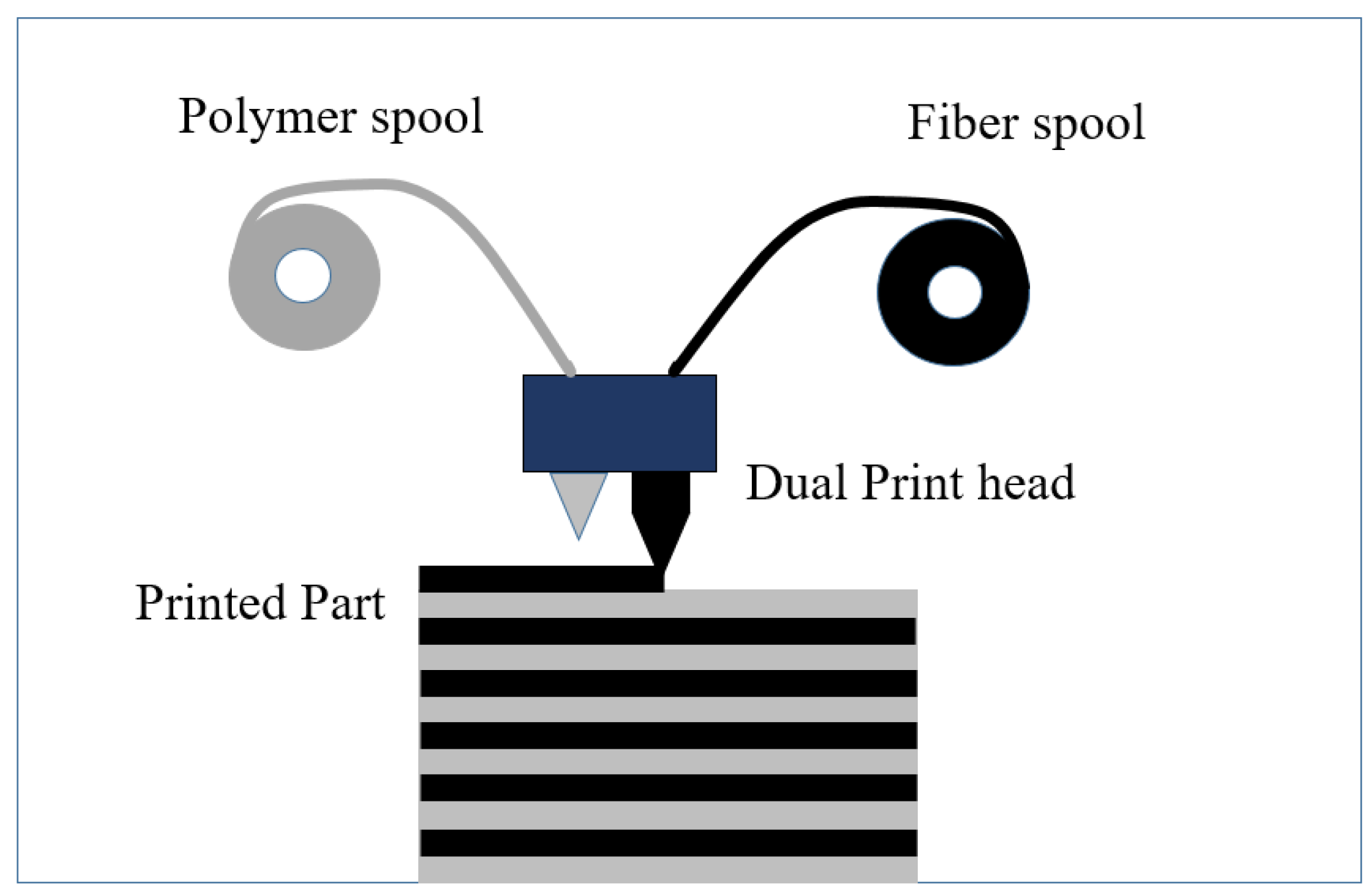
A MF desktop 3D printing machine was used to print the test specimens. The machine has two separate printing heads, one for matrix and one for reinforcing filaments. Figure 2 demonstrates a schematic view of the MF machine. The printing head temperature for the nylon matrix was set on 265–270 °C. At this temperature, the polymer matrix turns into the molten state and as soon as it leaves the nozzle, starts to solidification. The fiber materials do not melt at that temperature, but they are laid down horizontally layer by layer in the nylon matrix. Filaments are sliced layer by layer to complete the specimen on a non-heated printing bed. The printed layer thickness for nylon, FG and Kevlar filaments were 0.1 mm, and for CF was 0.125 mm. Figure 3 demonstrates a schematic view of matrix arrangement in CFRAM specimen.
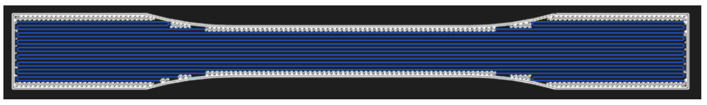
The tensile test was conducted in accordance with the American Standard Test Model (ASTM) D638, the standard test method for tensile properties of plastics [31,32]. Each test was repeated three times and the reported results are the mean values of reported results. The tensile specimens made from nylon and reinforced with CF, FG, and Kevlar were produced with a MF 3D printer, and the effect of printing parameters on tensile properties were investigated. The Instron 5582 was used as the tensile test machine. The machine is equipped with an extensometer to measure the displacement. Figure 4 demonstrates the fiber orientation of tensile specimens. The blue lines represent fiber reinforcement in the composite.
All the tensile specimens were printed with controlled printing parameters, including layer thickness, matrix type, fiber type, infill density, and infill pattern. To study the effect of each parameter, other parameters were kept constant. Different fibers of CF, FG, and Kevlar with different fiber volume percentages of 0%, 8%, 18%, 33%, and 60% were studied. Different infill densities of 10%, 56%, and 80%, and different infill patterns of rectilinear and triangular were investigated.
3. Results and Discussion
3.1. Tensile Analysis
The tensile test was conducted to measure the ultimate tensile strength (UTS) and elastic modulus (Em) of specimens. Furthermore, the effects of fiber type, matrix type, fiber volume fraction, layer thickness, matrix infill density, and matrix infill pattern on tensile strength and elastic modulus were studied. Moreover, a comparison was conducted between the tensile properties of CFRAM components, metals, and conventional polymer composites and popular AM polymer parts.
3.2. Effect of Fiber Volume Fraction on Tensile Properties
The effect of fiber volume fraction on tensile properties of nylon reinforced components was investigated. The infill density of 56%, thickness layer of 0.125, and infill pattern of rectilinear were used as default settings for the specimens. The tensile specimen in horizontal printing orientation is made of 40 layers, and the number of reinforcing fibers is determined according to the desired fiber volume fraction in the test specimen. Figure 5 demonstrates the schematic representation of layers in a CFRAM tensile specimen. Different specimens of nylon-CF, nylon-FG, and nylon-Kevlar were studied. Different volume fractions of 0%, 8%, 18%, 33%, and 60% were added to composite and tensile strength and elastic modulus were measured.
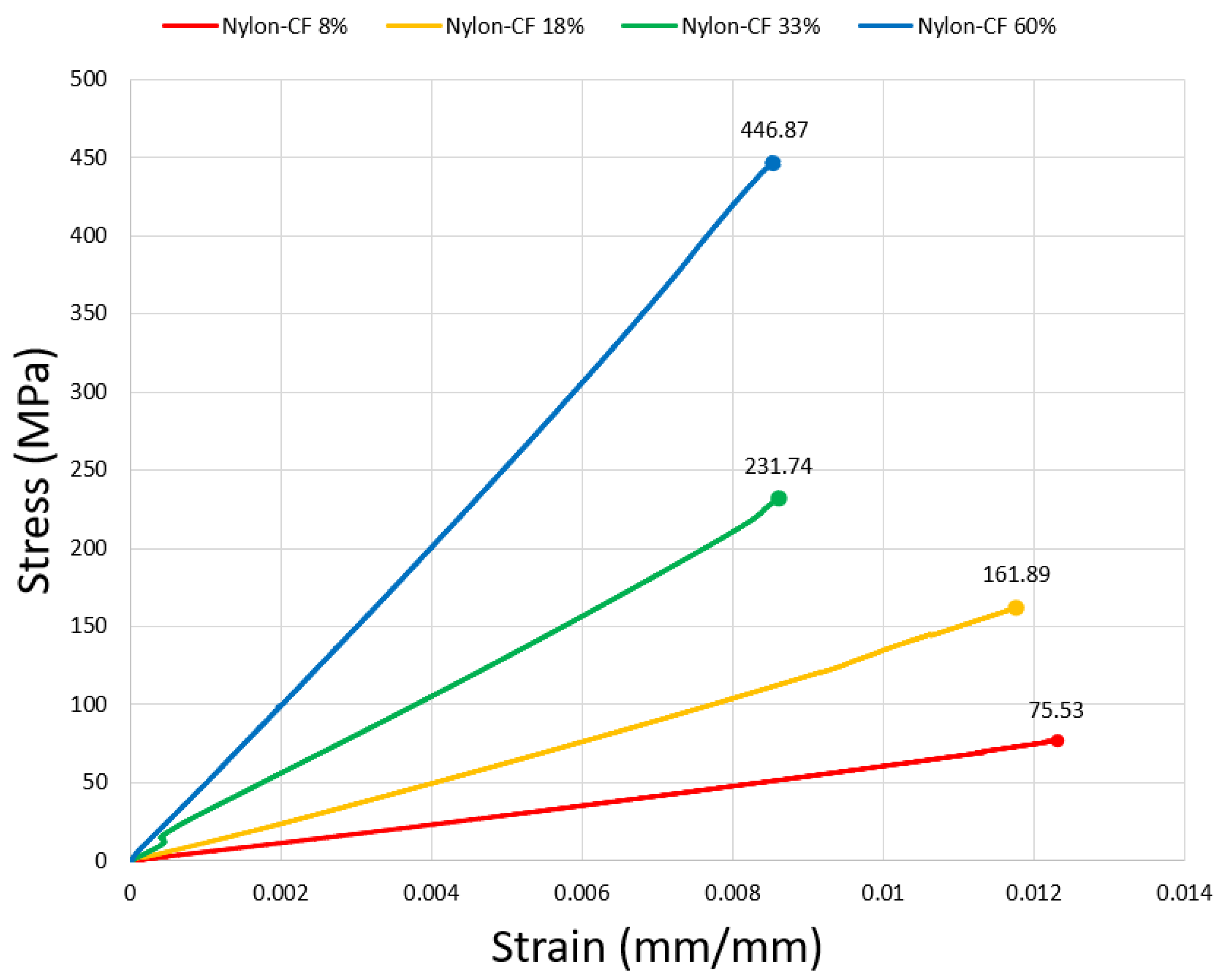
The stress–strain curve for nylon-CF specimens is shown in Figure 6. The highest value on the vertical axis shows the ultimate tensile strength, and the slope of the stress–strain graph represents the elastic modulus of composite. Results show that the fiber reinforcement boosts the tensile properties of 3D-printed nylon. As shown, fiber-reinforced specimens show linear graphs, demonstrating a brittle behavior of CFRAM components. Analyzing the graphs shows that (1) as the fiber content increases, the tensile strength and elastic modulus of composite enhance, (2) as the fiber content increases, the strain percentage of composite reduces, (3) CF improves the tensile properties of nylon more than FG and Kevlar.
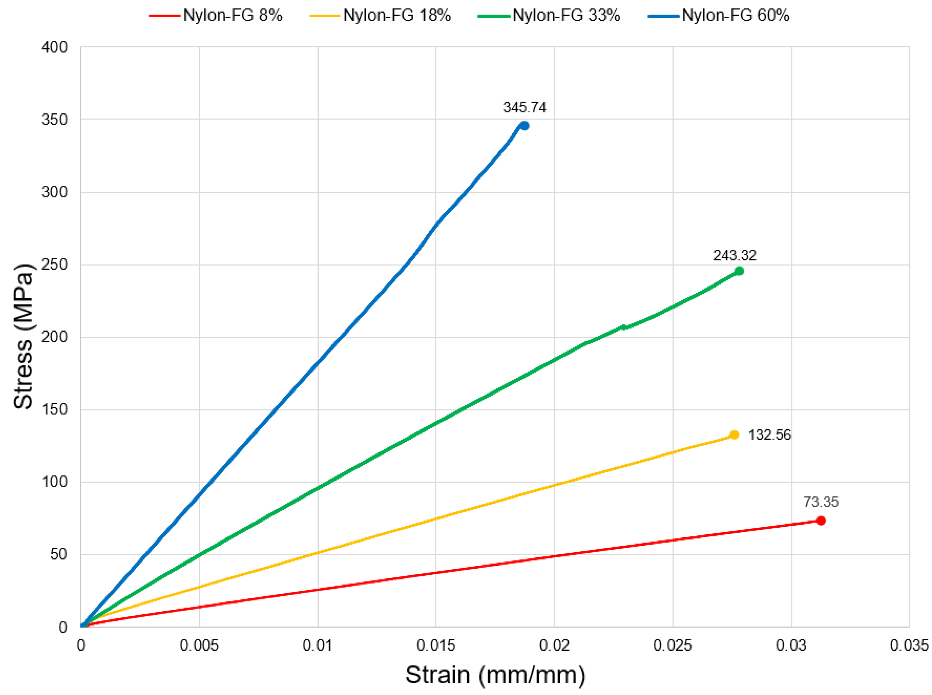
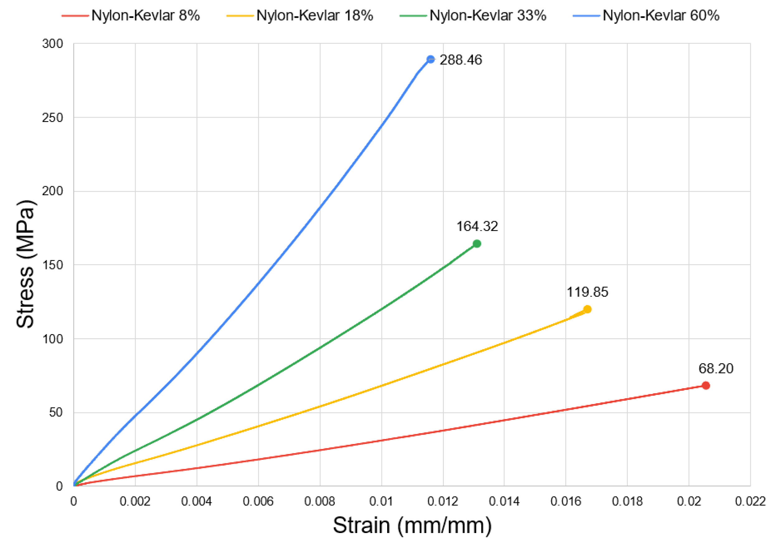
As can be seen in Figure 6, changing CF volume fraction from 0% to 60% enhances the ultimate strength of CFRAM specimens from 19.17 MPa to 446.87 MPa, which is an increase of 2231%. The obtained tensile strength of 446.87 MPa is much higher than the strength of nylon and a bit higher than the strength of Aluminum 6061 reported by [33]. Fiber has higher tensile strength and elastic modulus compared to matrix. As the fiber volume fraction increases, it controls the mechanical properties, and the main part of the load withstands by the fiber. As a result, tensile strength and elastic modulus improve. In the microstructural level, fiber inclusion restricts the movements of polymer chains, and consequently enhances the stiffness of matrix. This leads to a higher tensile strength and elastic modulus of the composite. Our observation during the tensile tests was that adding fiber makes the specimens brittle and reduces the strain amount compared with unreinforced nylon. Figure 7 and Figure 8 demonstrate the stress–strain graphs of CFRAM specimens of nylon-FG and nylon-Kevlar, consequently.
As shown in Figure 7 and Figure 9, changing FG content from 0% to 60% enhances the tensile strength from 19.17 MPa for un-reinforced nylon to 345.74 MPa, which is an increase of 1703%. Moreover, as shown in Figure 8 and Figure 9, changing Kevlar content from 0% to 60% enhances the tensile strength from 19.17 MPa to 288.46 MPa, which is an increase of 1404%.
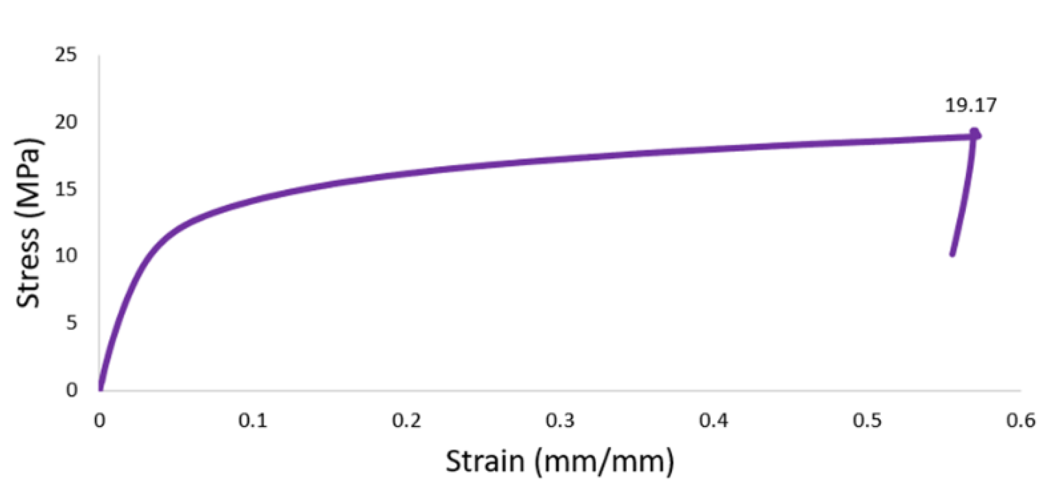
The tensile properties of 3D-printed unreinforced nylon were studied for comparison. The nylon specimen was printed with the same printing parameters as reinforced specimens. The stress–strain graph of neat nylon is shown in Figure 9. As can be seen, unreinforced nylon shows 19.17 MPa tensile strength which CF reinforcement can improve the tensile strength up to 446.87 MPa (Figure 6), which is an enhancement of 2200%. Furthermore, the nylon specimen shows a much higher strain amount compared to the reinforced specimens. Strain amount recorded for nylon was 0.57 mm/mm, while the maximum strain amount observed for CFRAM of nylon-CF with 60% volume fraction was 0.00854 mm/mm. This shows that the strain amount of nylon is 66.74 times higher than the strain amount of CFRAM with 60% CF volume fraction. As shown, unreinforced nylon demonstrates a plastic behavior with a small deformation at the beginning, following a high strain percentage. Our observation was that the specimen has much larger elongation at break compared to the reinforced specimens.
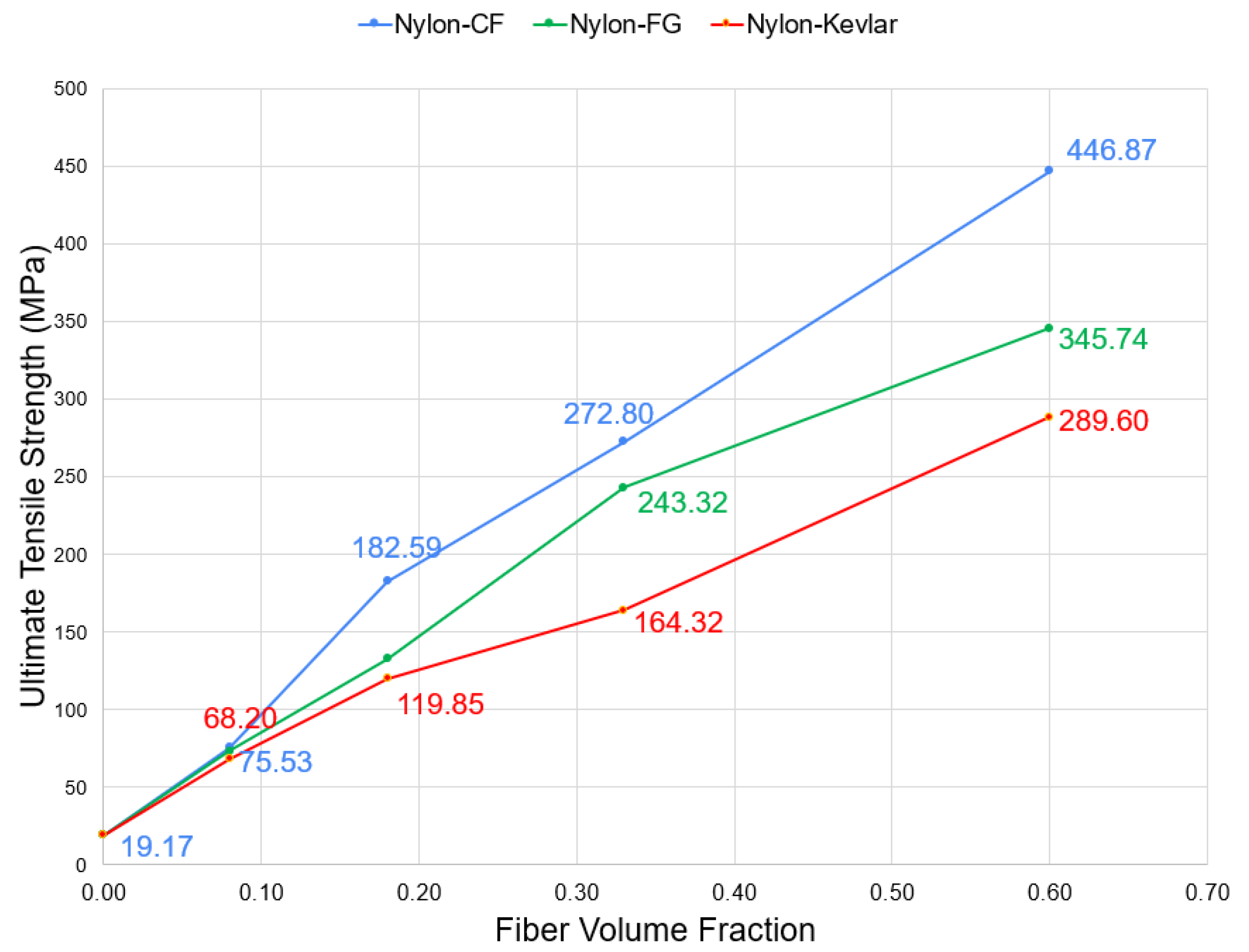
The tensile specimen of CFRAM nylon reinforced with fiber contains 40 layers. Each of the layers can be assigned to be matrix or fiber (except two top and two bottom layers which are nylon by default). Different layers of 4, 9, 18, and 36 were included into the part and consequently different Vf of 8%, 18%, 33%, and 60% were produced. Figure 10 and Figure 11 demonstrate the results for the effect of Vf on tensile strength of CFRAM components reinforced with CF, FG, and Kevlar. As shown, increasing Vf improves the tensile strength for all specimens. Our observation during the test showed that the nylon has ductile behavior and as the fiber content increase, the behavior of nylon becomes more brittle.
As shown in Figure 11, nylon-CF shows higher performance compared to other specimens. Ultimate tensile strength is the maximum tensile stress amount that an object can withstand before fracture. As can be seen, CF addition enhances the UTS of composite from 19.17 MPa to 446.87 MPa, which is an increase of 2231%. Increasing fiber content from 0% to 60%, improves the UTS of nylon-FG up to 1703%, and increasing fiber content from 0% to 60%, improves the UTS of nylon-Kevlar up to 1404%.
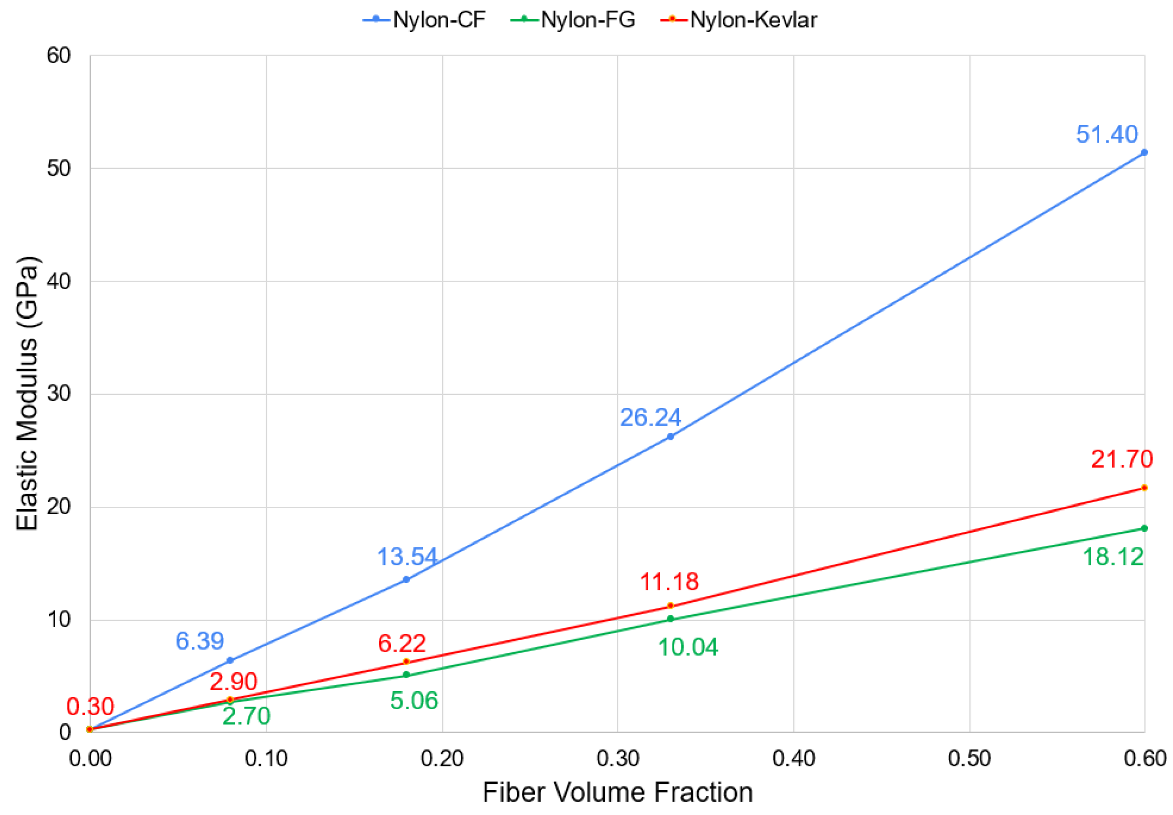
Figure 11 shows the effect of fiber volume content on elastic modulus of CFRAM components. As shown, the elastic modulus enhances linearly with fiber content. Unreinforced nylon shows an elastic modulus of 0.297 GPa, while CF inclusion enhances the Em of composite to 51.4 GPa, which is an enhancement of 17,206%. This enhancement indicates the main role that CF plays for improvement of tensile properties. Moreover, increasing fiber content from 0% to 60%, improves the Em of nylon-FG from 0.297 GPA to 21.70 GPa, which is an enhancement of up to 7206%, and increasing fiber content from 0% to 60% improves the Em of nylon-Kevlar from 0.29 GPa to 18.12 GPa, up to 6001%.
3.3. Comparison of Tensile Performance of CFRAM Components with Conventional Composites
In this section, a comprehensive evaluation is conducted to compare the mechanical properties of CFRAM components and conventional materials used for industrial applications. Three groups of materials that are conventional in engineering applications are studied here. The tensile properties of these materials are compared with each other. Materials are categorized in three groups: metals, compression molded fiber-reinforced composites, and CFRAM composites. Tensile properties of some conventional AM polymers are also provided for reference.
Although metals have strong mechanical properties, their main drawback is high density. In the last decades, polymer composites showed that they are good candidates for industrial applications like automotive industry to reduce weight, price, and production time without sacrificing mechanical properties. Conventional methods to produce reinforced polymers include the injection molding and compression molding. The extra molding steps restrict the utilization of this method for production of complicated parts. The CFRAM technology presented in this research study is exempt from molding and the need for heavy equipment and operator [34].
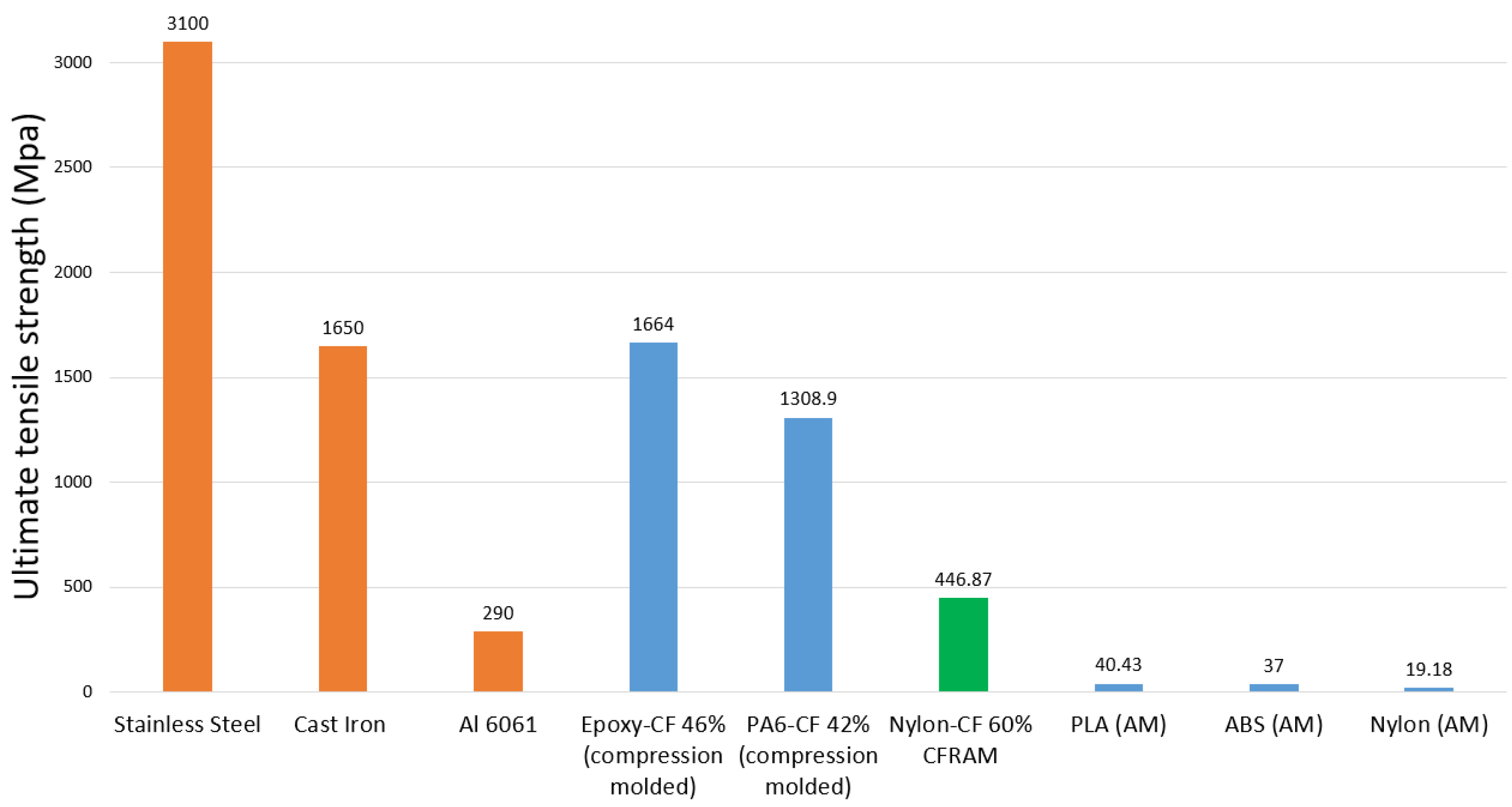
Figure 12 compares the ultimate tensile strength of different materials. As can be seen, the ultimate tensile strength of stainless steel, cast iron, compression molded epoxy composites, and compression molded nylon composites are 3100 [35], 1650 [35], 1664 [36], and 1308 MPa [36], respectively. Tensile strength of CFRAM nylon-CF with 60% volume fraction equals 446.87 MPa, which is higher than Aluminum 6061 with 290 MPa. As can be seen, additively manufactured PLA, ABS, and nylon have tensile strength much lower than metals and reinforced polymers.
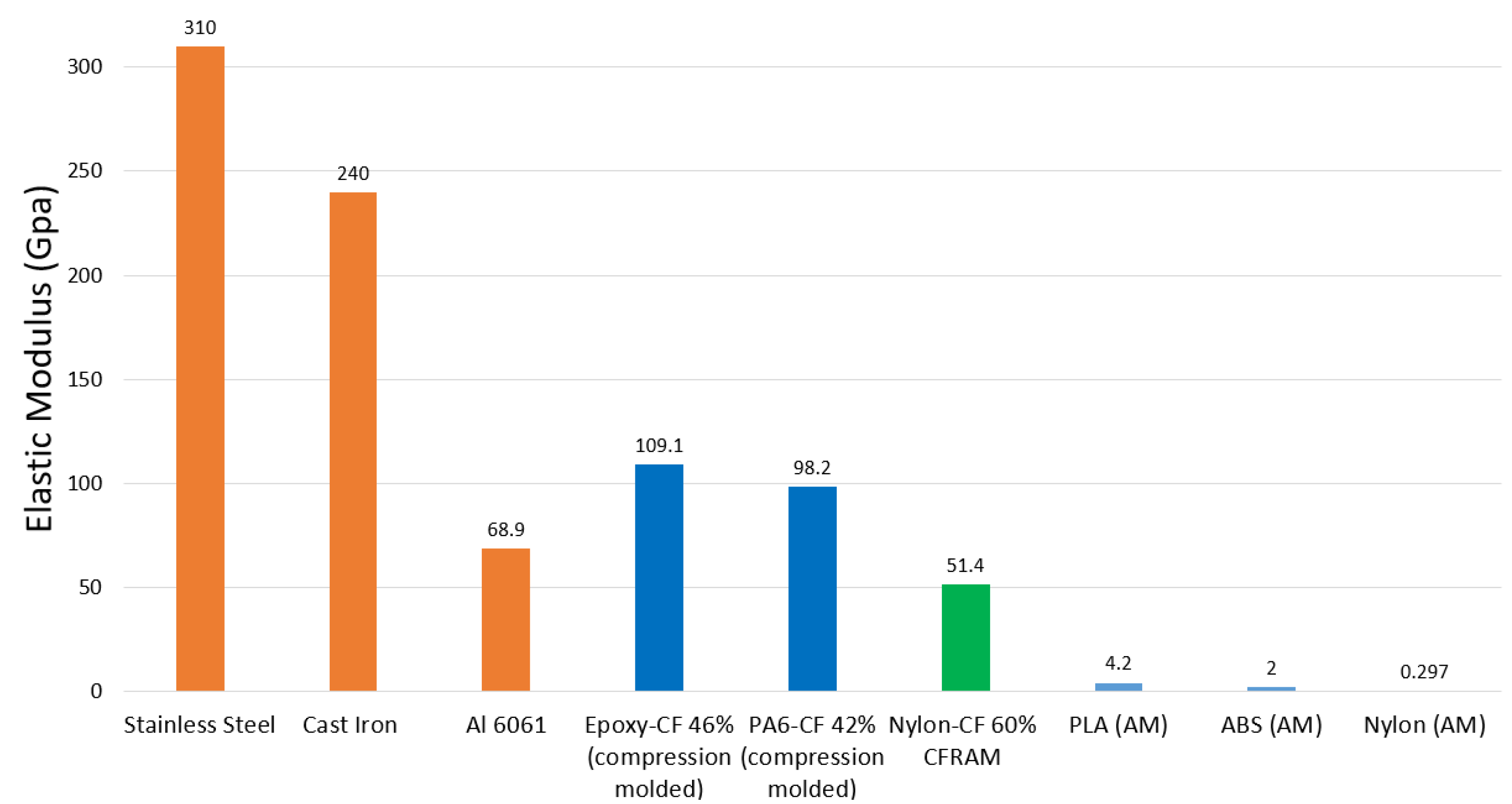
Figure 13 compares the elastic modulus of materials. As shown, the elastic modulus of stainless steel, cast iron, compression molded epoxy composites, and molded nylon-CF composite are 310, 240, 109, and 98 GPa, respectively. Furthermore, additively manufactured PLA, ABS, and nylon have tensile strength much lower than metals and reinforced polymers.
3.4. Fracture Study of CFRAM Components during the Tensile Test
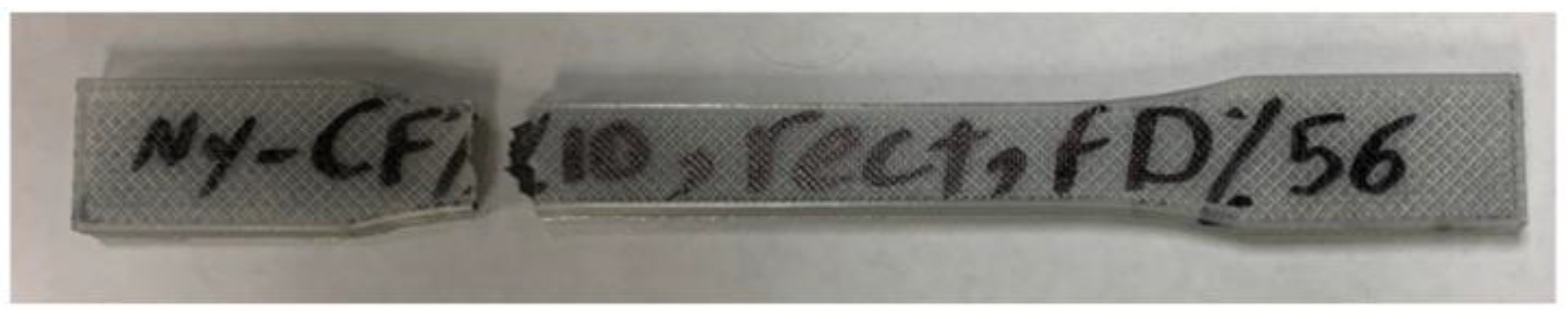
The fracture mechanism of tensile specimens after the tensile test was investigated to draw a conclusion on specimens’ breakage pattern. It was observed that the fracture point for all tensile specimens was at the shoulder of the specimen. The starting points are the areas of the specimen that lack fiber compared to other parts of the specimen. Therefore, they serve as the stress concentration areas to start a crack, propagation of crack and finally fracture of specimen. Furthermore, the fiber discontinuity at the corners cause the corners to become weaker compared to other areas, and failure happens at that point. The same observation is reported by Dickson et al. [22] who reported that the tensile specimens fail at the shoulder. The actual fractured specimen of nylon reinforced with 10% Vf CF is shown in Figure 14.
3.5. Microstructural Analysis
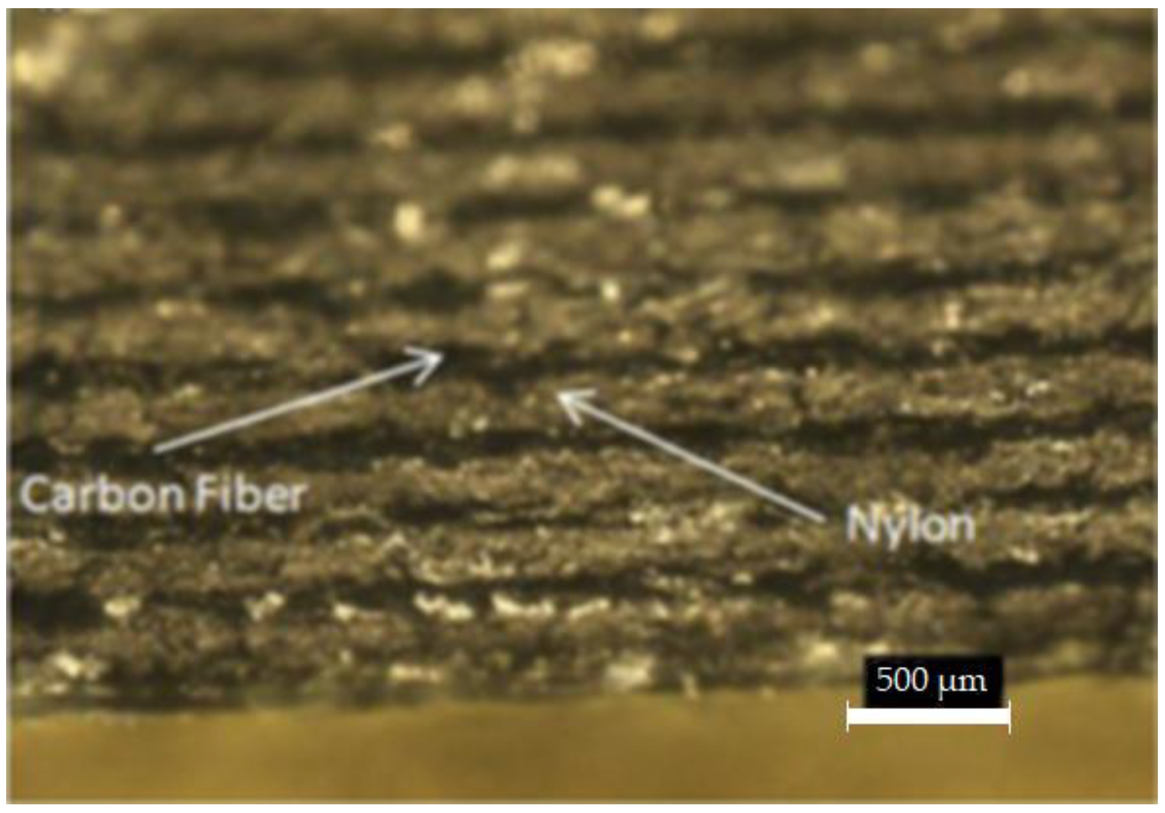
The microstructural analysis was conducted to study the fracture mechanism, internal morphology, interlayer adhesion, and printing quality of specimens. The test specimens were examined using SEM microscopy. The cross-sectional view of CFRAM component of nylon-CF is shown in Figure 15. Layers of CF and nylon are observed in figure.
The interlayer adhesion between the polymer and fiber layers plays a critical role in determining the mechanical properties of the composite materials. Increasing the interlayer adhesion improves the mechanical properties, including toughness, creep resistance, and strength [37,38,39]. Additionally, voids created during the printing process serve as sites for crack nucleation and reduce the material density, as well as the thermal, mechanical, and conductive properties [40,41]. The interlayer adhesion, intrinsic properties of materials, and voids in the structure are the main factors determining the durability and fracture mechanism of CFRAM components [42]. A firm adhesive interface which means an ideal impregnation of matrix and strong bonding between fibers and matrix is necessary for the efficient transfer of stress throughout the interface [43,44]. The stronger adhesion improves the mechanical properties including tensile performance [45]. Voids serve as nucleation sites for crack growth due to the reduction of interlayer adhesion.
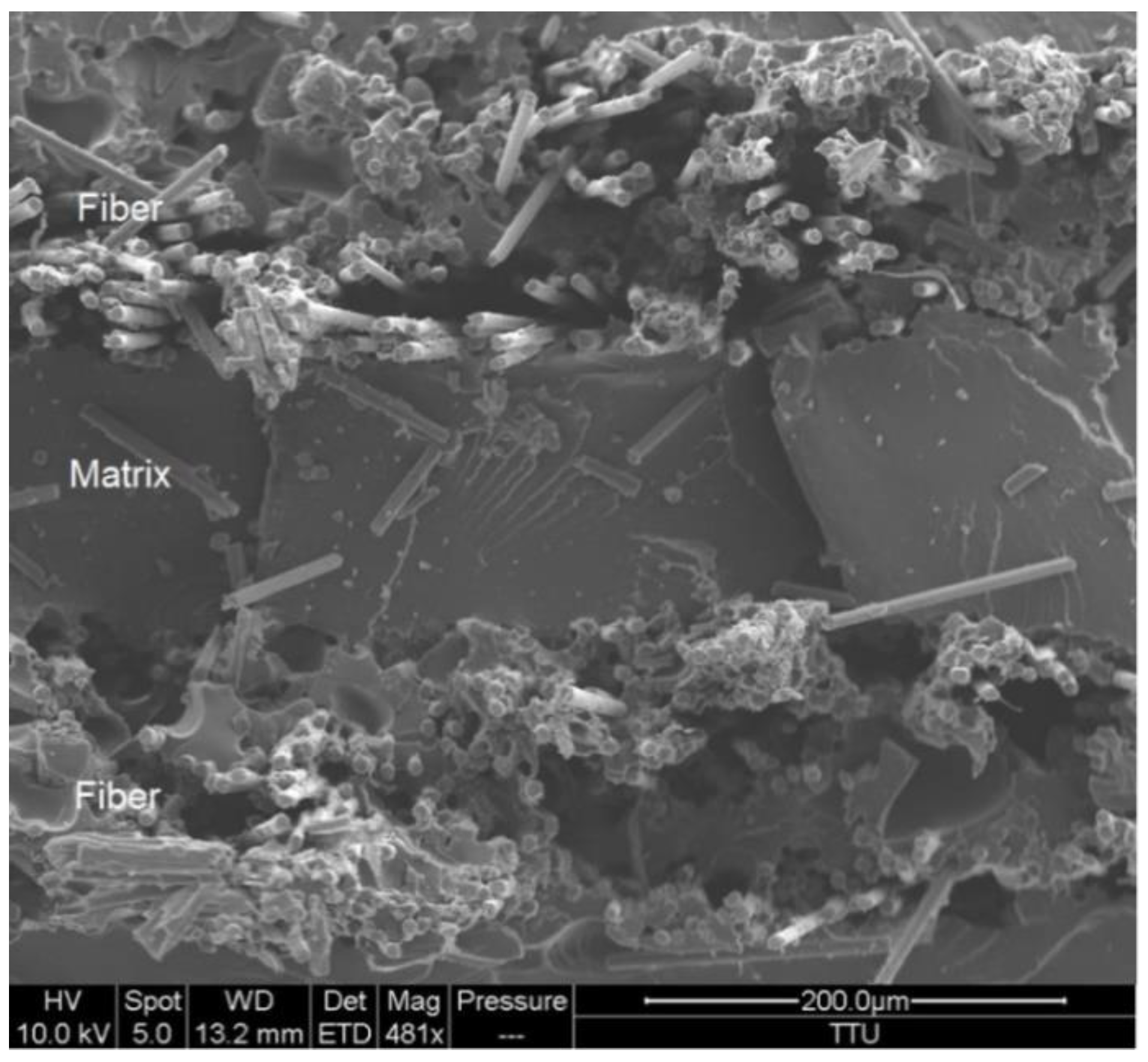
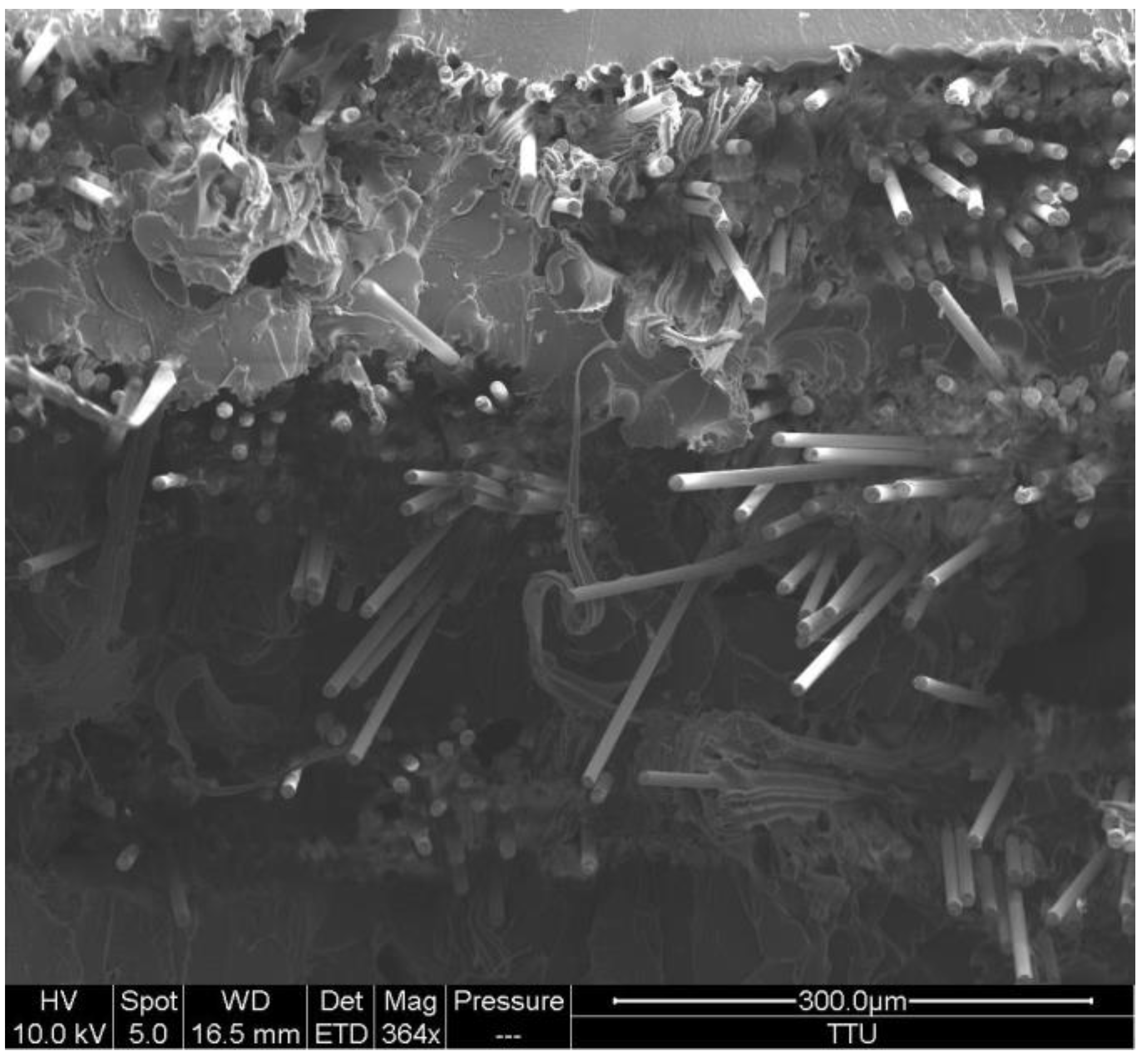
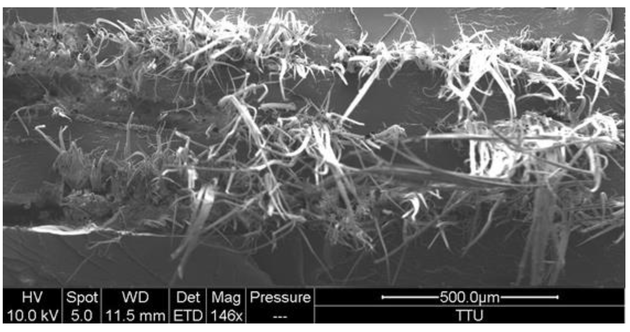
Figure 16, Figure 17 and Figure 18 demonstrate the SEM micrographs from the cross section of CFRAM nylon-CF, nylon-FG, and nylon-Kevlar specimens, respectively. In the SEM micrograph, it is confirmed that the morphology is layer by layer.
SEM micrographs confirm that the fiber breakage and fiber pull-out are the main fracture mechanisms of CFRAM components. The pulled out fibers and strands of broken fibers are observed in Figure 17 and Figure 18. The ruptured fibers in the fracture interface indicated that the load was effectively transferred from the matrix to fiber. The applied load causes the fiber breakage in the structure. The broken fibers are pulled out of the matrix and leads to the fracture of composite. SEM studies were also used to determine the extent of the void presence (porosity) within the composites. The voids were observed at the minimal level within the polymer matrix and the interface. The gaps seem to be generated by the pulled-out fibers existing on the fracture interface of the specimens [46].
3.6. Effect of Process Parameters
Layer thickness is one of the significant printing parameters affecting the mechanical properties and printing time of the specimens [47,48]. The effect of layer thickness on the tensile properties of nylon specimens was investigated. Specimens with three different layer thicknesses of 0.1 mm, 0.125 mm, and 0.2 mm were printed and tested. As can be seen in Figure 19, increasing layer thickness from 0.1 mm to 0.2 mm elevates the UTS of 3D-printed nylon from 15.94 MPa to 19.52 MPa, which shows an improvement of 22%.
As shown, the UTS and Em of nylon rises with increasing layer thickness. Increasing the layer thickness in the specimen with the same fiber fraction reduces the number of layers in same volume and consequently reduces the interface areas between the layers. The interface is the area for crack nucleation and crack growth, which leads to the fracture of the specimen. Higher thickness reduces the interface and this leads to a higher strength value. Thus, this improvement can be attributed to reducing the interface in the structure. Table 3 demonstrates the effect of layer thickness on tensile strength and elastic modulus of nylon.
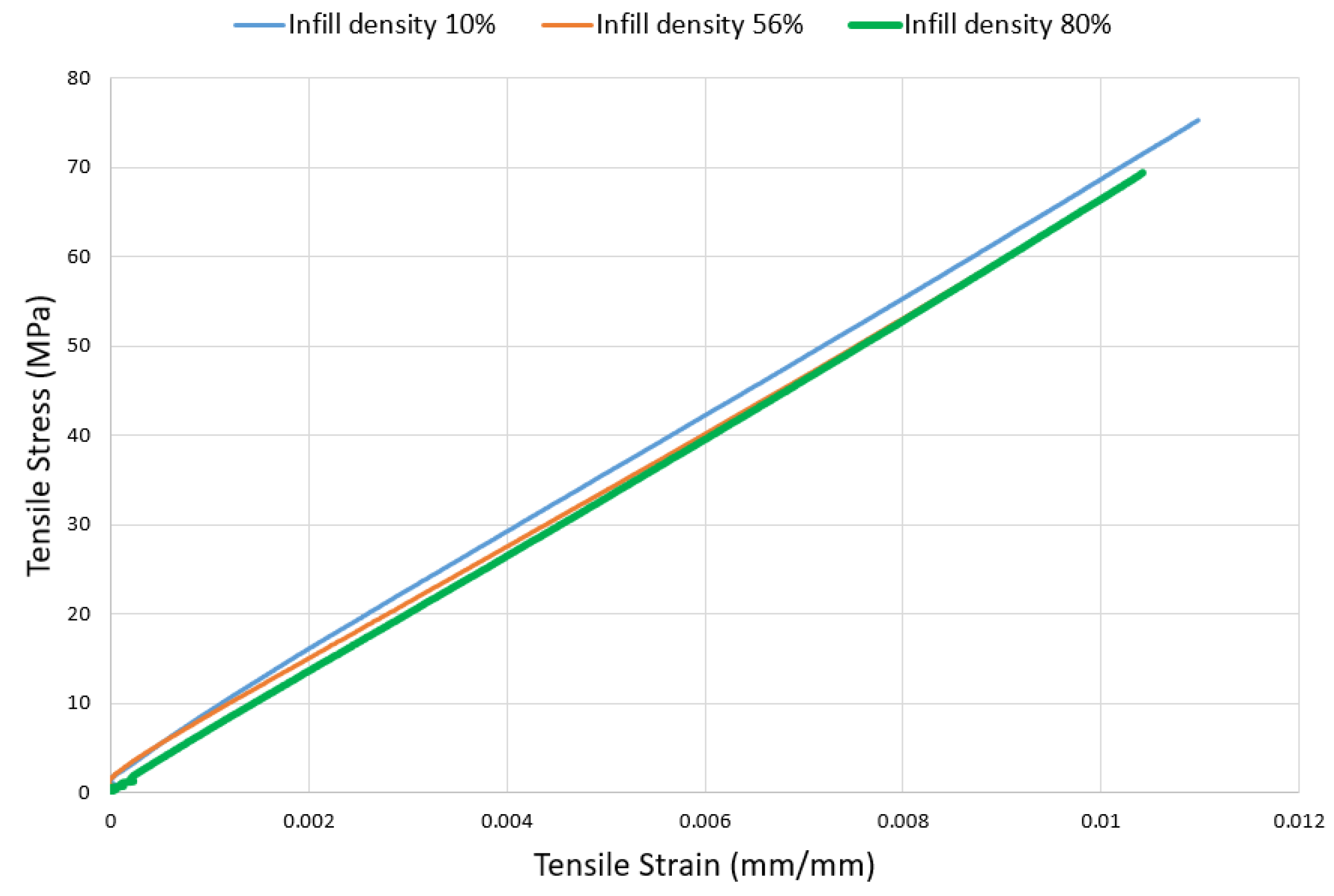
The infill density defines the plastic amount used inside the printed part and it is considered as one of the factors affecting mechanical properties, printing time, and price of the printed part [49]. Tensile specimens with three different infill densities of 10%, 56%, and 80% at room temperature were tested. For the nylon-CF specimens, the stress–strain graph is linear and changing infill density does not have much effect on tensile results. Figure 20 demonstrates the stress–strain graphs of nylon composites containing 10% volume fraction of CF. As shown, the tensile strength for specimens with 10%, 56%, and 80% infill density equals 75.13 MPa, 65.93 MPa, and 69.27 MPa, respectively, while the elastic modulus for all three specimens equals 6.6 GPa. As can be seen, graphs for all three different specimens are very close to each other, which demonstrate that the infill density does not change the tensile strength and the elastic modulus of CFRAM nylon-CF. This may be attributed to the fact that for fiber-reinforced specimens, fibers are the main bear-loading component of the composite. In fact, the load is applied to the fibers, not on the matrix. Thus, changing the infill density from 10% to 80% does not have a significant effect on the tensile performance of nylon-CF CFRAM specimens. Therefore, for the nylon-CF specimen, increasing infill density does not have a considerable effect on the tensile strength and elastic modulus. Table 4 tabulates the results for the effect of infill density of tensile strength and elastic modulus.
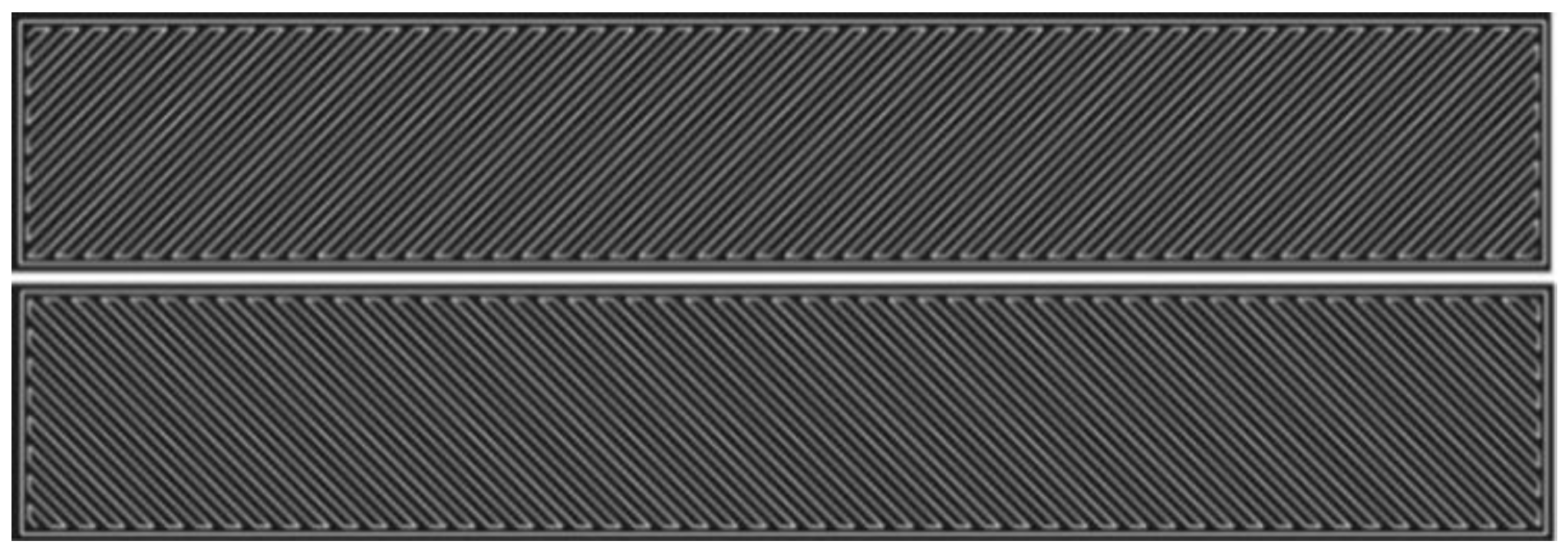
The effect of infill pattern on tensile properties of 3D-printed nylon was studied. Changing the infill patterns can affect the object’s final strength, rigidity, and flexibility without changing the part’s weight, materials used, or printing time. Two different infill patterns of rectilinear and triangular with the same infill density of 56% were tested. Figure 21 demonstrates the tensile specimens with rectilinear and triangular infill patterns and with the same infill densities of 56% and the same layer thickness of 0.125 mm.
According to the results obtained from tensile test, a triangular infill pattern shows an ultimate strength of 12.62 MPa, while a rectilinear infill pattern shows ultimate strength of 18.93 MPa with more strain amount. The reason for this observation is attributed to the orientation of the matrix layers in the structure. In a rectilinear infill pattern, more strands are oriented in the axial direction compared to the triangular infill pattern. Thus, the rectilinear pattern shows a higher strength and elastic modulus compared to a triangular pattern. The elastic modulus of nylon with a rectilinear pattern is 0.373 GPa, which is 19% higher than a triangular infill pattern with 0.313 GPa.
3.7. Cost Analysis
In this section, the effect of fiber volume fraction on the price of CFRAM components of nylon-CF, nylon-FG and nylon-Kevlar is discussed. The price estimation is based on the price of used materials and does not consider electricity and other expenses. Five different fiber volume fractions of 0%, 8%, 18%, 33%, and 60% were used. The results show that for all specimens, increasing fiber volume fraction increases the price of the specimen. Results show that the price of unreinforced nylon equals $2.17, which an inclusion of 8%, 18%, 33% and 60% volume fraction of CF improves the price of nylon up to $5.13, $8.61, $14.87 and $27.26, respectively. The enhancement of the price for nylon-FG and nylon-KV with 60% volume fraction equals 582% and 782%, respectively.
3.8. Printing Time
The effect of fiber volume fraction on printing time of CFRAM specimens of nylon-CF, nylon-FG, and nylon-KV was studied. The results show that for all specimens, increasing fiber volume fraction increases the printing time of specimen. The results show that printing time of the nylon specimen is 93 min and CF reinforcement with 8%, 18%, 33% and 60% volume fraction can increase the printing time to 117, 130, 154 and 199 min, respectively. The increase of fiber volume fraction to 60% enhances the printing time of nylon-FG, nylon-KV, up to 155% and 158%, respectively.
4. Conclusions
The focus of the study is to drive a benchmarking study on tensile properties of CFRAM parts for the industrial applications. The tensile performance of CFRAM parts of nylon-CF, nylon-FG and nylon-Kevlar, with fiber volume fractions of 0, 8%, 18%, 33% and 60% were studied and the effect of process parameters on tensile strength and elastic modulus were analyzed. The results showed that fiber reinforcement with 60% volume fraction can improve the tensile strength and elastic modulus of CFRAM components up to 2231% and 17,206%, respectively. The results showed that a CFRAM component has a tensile strength higher than Aluminum 6061. The tensile properties of CFRAM components are lower than stainless steel and conventional molded composites, but the weight of CFRAM components is much lighter than metals and the manufacturing process of CFRAM components is much easier than metals and conventional composites. The microstructural analysis was conducted to study the fracture mechanism, internal morphology, interlayer adhesion, and printing quality of the specimens. The SEM results showed that fiber breakage and fiber pull-out are the main fracture mechanisms of CFRAM components. The effect of fiber inclusion on cost and printing time of specimens were studied.
Author Contributions
Data curation, M.M.; Formal analysis, M.M.; Investigation, M.M.; Methodology, M.M.; Project administration, I.F.; Supervision, I.F.; Writing—original draft, M.M.; Writing—review & editing, M.M. and I.F. All authors have read and agreed to the published version of the manuscript.
Funding
This research was funded by Center for Manufacturing Research, Tennessee Tech University, Cookeville, TN 38501.
Institutional Review Board Statement
Not applicable.
Informed Consent Statement
Informed Informed consent was obtained from all subjects involved in the study.
Data Availability Statement
Available Upon Request.
Acknowledgments
The technical and financial support provided by the Center for Manufacturing Research at Tennessee Tech University is greatly appreciated.
Conflicts of Interest
The authors declare no conflict of interest.
References
- Wimpenny, D.I.; Pandey, P.M.; Kumar, L.J. (Eds.) Advances in 3D Printing & Additive Manufacturing Technologies; Springer: Singapore, 2017. [Google Scholar]
- Li, N.; Huang, S.; Zhang, G.; Qin, R.; Liu, W.; Xiong, H.; Shi, G.; Blackburn, J. Progress in additive manufacturing on new materials: A review. J. Mater. Sci. Technol. 2019, 35, 242–269. [Google Scholar] [CrossRef]
- Campbell, I.; Diegel, O.; Kowen, J.; Wohlers, T. Wohlers Report 2018: 3D Printing and Additive Manufacturing State of the Industry: Annual Worldwide Progress Report; Wohlers Associates: Fort Collins, CO, USA, 2018. [Google Scholar]
- Mortazavian, E.; Wang, Z.; Teng, H. Thermal-Mechanical Study of 3D Printing Technology for Rail Repair. In ASME 2018 International Mechanical Engineering Congress and Exposition. American Society of Mechanical Engineers Digital Collection; ASME International: New York, NY, USA, 2018. [Google Scholar]
- Attaran, M. The rise of 3-D printing: The advantages of additive manufacturing over traditional manufacturing. Bus. Horiz. 2017, 60, 677–688. [Google Scholar] [CrossRef]
- Mortazavian, E.; Wang, Z.; Teng, H. Thermal-Kinetic-Mechanical Modeling of Laser Powder Deposition Process for Rail Repair. In ASME 2019 International Mechanical Engineering Congress and Exposition. American Society of Mechanical Engineers Digital Collection; ASME International: New York, NY, USA, 2019. [Google Scholar]
- Caminero, M.; Chacón, J.M.; García-Moreno, I.; Rodríguez, G. Impact damage resistance of 3D printed continuous fibre reinforced thermoplastic composites using fused deposition modelling. Compos. Part B Eng. 2018, 148, 93–103. [Google Scholar] [CrossRef]
- Ngo, T.D.; Kashani, A.; Imbalzano, G.; Nguyen, K.T.Q.; Hui, D. Additive manufacturing (3D printing): A review of materials, methods, applications and challenges. Compos. Part. B Eng. 2018, 143, 172–196. [Google Scholar] [CrossRef]
- Calvo, M.A.; López-Gómez, I.; Chamberlain-Simon, N.; Leon-Salazar, J.L.; Guillén-Girón, T.; Corrales-Cordero, J.S.; Sánchez-Brenes, O. Evaluation of compressive and flexural properties of continuous fiber fabrication additive manufacturing technology. Addit. Manuf. 2018, 22, 157–164. [Google Scholar] [CrossRef]
- Gardan, J. Additive manufacturing technologies: State of the art and trends. Int. J. Prod. Res. 2016, 54, 3118–3132. [Google Scholar] [CrossRef]
- Kabir, S.M.F.; Mathur, K.; Seyam, A.-F.M. A critical review on 3D printed continuous fiber-reinforced composites: History, mechanism, materials and properties. Compos. Struct. 2020, 232, 111476. [Google Scholar] [CrossRef]
- Hao, W.; Liu, Y.; Zhou, H.; Chen, H.; Fang, D. Preparation and characterization of 3D printed continuous carbon fiber reinforced thermosetting composites. Polym. Test. 2018, 65, 29–34. [Google Scholar] [CrossRef]
- Dong, G.; Tang, Y.; Li, D.; Zhao, Y.F. Mechanical Properties of Continuous Kevlar Fiber Reinforced Composites Fabricated by Fused Deposition Modeling Process. Procedia Manuf. 2018, 26, 774–781. [Google Scholar] [CrossRef]
- Melenka, G.W.; Cheung, B.K.O.; Schofield, J.S.; Dawson, M.R.; Carey, J.P. Evaluation and prediction of the tensile properties of continuous fiber-reinforced 3D printed structures. Compos. Struct. 2016, 153, 866–875. [Google Scholar] [CrossRef]
- Mark, G.T.; Gozdz, A.S. Three Dimensional Printing. U.S. Patent No. 9,149,988, 6 October 2015. [Google Scholar]
- Van Der Klift, F.; Koga, Y.; Todoroki, A.; Ueda, M.; Hirano, Y.; Matsuzaki, R. 3D printing of continuous carbon fibre reinforced thermo-plastic (CFRTP) tensile test specimens. Open J. Compos. Mater. 2016, 6, 18–27. [Google Scholar] [CrossRef] [Green Version]
- Mark, G.T.; Woodruff, R.B.; Parangi, A.L.; Benhaim, D.S.; Sklaroff, B.T. Multiaxis Fiber Reinforcement for 3D Printing. U.S. Patent No. 9,815,268, 14 November 2017. [Google Scholar]
- Mark, G.T.; Gozdz, A.S. Three Dimensional Printing of Composite Reinforced Structures. U.S. Patent No. 9,186,848, 17 November 2015. [Google Scholar]
- Mark, G.T.; Gozdz, A.S. Three Dimensional Printing with Composite Filament Fabrication. U.S. Patent 9,156,205 B2, 13 October 2015. [Google Scholar]
- Fidan, I.; Imeri, A.; Gupta, A.; Hasanov, S.; Nasirov, A.; Elliott, A.; Alifui-Segbaya, F.; Nanami, N. The trends and challenges of fiber reinforced additive manufacturing. Int. J. Adv. Manuf. Technol. 2019, 102, 1801–1818. [Google Scholar] [CrossRef]
- Mohammadizadeh, M.; Fidan, I.; Allen, M.; Imeri, A. Creep behavior analysis of additively manufactured fiber-reinforced components. Int. J. Adv. Manuf. Technol. 2018, 99, 1225–1234. [Google Scholar] [CrossRef]
- Dickson, A.N.; Barry, J.N.; McDonnell, K.A.; Dowling, D. Fabrication of continuous carbon, glass and Kevlar fibre reinforced polymer composites using additive manufacturing. Addit. Manuf. 2017, 16, 146–152. [Google Scholar] [CrossRef]
- Justo, J.; Tavara, L.; García-Guzmán, L.; París, F. Characterization of 3D printed long fibre reinforced composites. Compos. Struct. 2018, 185, 537–548. [Google Scholar] [CrossRef]
- Dizon, J.R.C.; Espera, A.H.; Chen, Q.; Advincula, R.C. Mechanical characterization of 3D-printed polymers. Addit. Manuf. 2018, 20, 44–67. [Google Scholar] [CrossRef]
- Matsuzaki, R.; Ueda, M.; Namiki, M.; Jeong, T.-K.; Asahara, H.; Horiguchi, K.; Nakamura, T.; Todoroki, A.; Hirano, Y. Three-dimensional printing of continuous-fiber composites by in-nozzle impregnation. Sci. Rep. 2016, 6, 23058. [Google Scholar] [CrossRef]
- Caminero, M.A.; Chacon, J.M.; Garcia-Moreno, I.; Reverte, J.M. Interlaminar bonding performance of 3D Printed continuous fiber reinforced thermoplastic composites using fused deposition modelling. Polym. Test. 2018, 68, 415–423. [Google Scholar] [CrossRef]
- Goh, G.D.; Dikshit, V.; Nagalingam, A.; Agarwala, S.; Sing, S.L.; Wei, J.; Yeong, W. Characterization of mechanical properties and fracture mode of additively manufactured carbon fiber and glass fiber reinforced thermoplastics. Mater. Des. 2018, 137, 79–89. [Google Scholar] [CrossRef]
- Kvalsvig, A.; Yuan, X.; Potgieter, J.; Cao, P. Analysing the tensile properties of 3D printed fibre reinforced thermoplastic composite specimens. In Proceedings of the 2017 24th International Conference on Mechatronics and Machine Vision in Practice (M2VIP), Auckland, New Zealand, 21–23 November 2017; pp. 1–6. [Google Scholar]
- Dickson, A.N.; Ross, K.-A.; Dowling, D. Additive manufacturing of woven carbon fibre polymer composites. Compos. Struct. 2018, 206, 637–643. [Google Scholar] [CrossRef]
- Blok, L.; Longana, M.L.; Yu, H.; Woods, B. An investigation into 3D printing of fibre reinforced thermoplastic composites. Addit. Manuf. 2018, 22, 176–186. [Google Scholar] [CrossRef]
- Gooch, J.W. ASTM D638. In Encyclopedic Dictionary of Polymers; Springer Science and Business Media LLC.: Berlin/Heidelberg, Germany, 2011; p. 51. [Google Scholar]
- Available online: https://www.astm.org/Standards/D638 (accessed on 2 February 2020).
- Naranjo-Lozada, J.; Ahuett-Garza, H.; Castañón, P.O.; Verbeeten, W.M.; Sáiz-González, D. Tensile properties and failure behavior of chopped and continuous carbon fiber composites produced by additive manufacturing. Addit. Manuf. 2019, 26, 227–241. [Google Scholar] [CrossRef]
- Mercado-Colnenero, J.M.; Martin-Doñate, C.; Moramarco, V.; Attolico, M.A.; Renna, G.; Rodriguez-Santiago, M.; Casavola, C. Mechanical Characterization of the plastic materialGF-PA6manufactured using FDM technology for a compression uniaxial stress field via an experiemntal and numerical analysis. Polymers 2020, 12, 246. [Google Scholar] [CrossRef] [Green Version]
- Available online: https://markforged.com (accessed on 1 February 2020).
- Ma, Y.; Ueda, M.; Yokozeki, T.; Sugahara, T.; Yang, Y.; Hamada, H. A comparative study of the mechanical properties and failure behavior of carbon fiber/epoxy and carbon fiber/polyamide 6 unidirectional composites. Compos. Struct. 2017, 160, 89–99. [Google Scholar] [CrossRef]
- Parandoush, P. Additive Manufacturing of High-Strength Continuous Fiber Reinforced Polymer Composites. Ph.D. Thesis, Kansas State University, Manhattan, KS, USA, 2019. [Google Scholar]
- Wang, Y.; Liu, Z.; Gu, H.; Cui, C.; Hao, J. Improved mechanical properties of 3D-printed SiC/PLA composite parts by microwave heating. J. Mater. Res. 2019, 34, 3412–3419. [Google Scholar] [CrossRef]
- Ning, F.; Cong, W.; Hu, Y.; Wang, H. Additive manufacturing of carbon fiber-reinforced plastic composites using fused deposition modeling: Effects of process parameters on tensile properties. J. Compos. Mater. 2017, 51, 451–462. [Google Scholar] [CrossRef]
- Quill, T.J.; Smith, M.K.; Zhou, T.; Baioumy, M.G.S.; Berenguer, J.P.; Cola, B.A.; Kalaitzidou, K.; Bougher, T.L. Thermal and mechanical properties of 3D printed boron nitride—ABS composites. Appl. Compos. Mater. 2017, 25, 1205–1217. [Google Scholar] [CrossRef]
- Mohammadizadeh, M.; Fidan, I. Thermal analysis of 3D Printed continuous fiber reinforced thermoplastic polymers for automotive applications. In Proceedings of the Solid Freeform Fabrication 2019: Proceedings of the 30th Annual International, Austin, TX, USA, 12–14 August 2019. [Google Scholar]
- Mohammadizadeh, M.; Imeri, A.; Fidan, I.; Elkelany, M. 3D printed fiber reinforced polymer composites—Structural analysis. Compos. Part B Eng. 2019, 175, 107112. [Google Scholar] [CrossRef]
- Mohammadizadeh, M. Mechanical and Thermal Analyses of Automotive Components Manufactured with 3D Printed Continuous Fiber Reinforced Thermoplastic Polymers. Ph.D. Thesis, Tennessee Technological University, Cookeville, TN, USA, 2020. [Google Scholar]
- Chamis, C.C. Mechanics of load transfer at the interface. Compos. Mater. 2016, 6, 31–77. [Google Scholar]
- Braga, R.; Magalhaes, P. Analysis of the mechanical and thermal properties of jute and glass fiber as reinforcement epoxy hybrid composites. Mater. Sci. Eng. C 2015, 56, 269–273. [Google Scholar] [CrossRef]
- Mohammadizadeh, M.; Fidan, I. Experimental Evaluation of Additively Manufactured Continuous Fiber Reinforced Nylon Composites. In TMS 2020 149th Annual Meeting & Exhibition Supplemental Proceedings; Springer Science and Business Media LLC.: Berlin/Heidelberg, Germany, 2020; pp. 321–328. [Google Scholar]
- Shubham, P.; Sikidar, A.; Chand, T. The Influence of Layer Thickness on Mechanical Properties of the 3D Printed ABS Polymer by Fused Deposition Modeling. Key Eng. Mater. 2016, 706, 63–67. [Google Scholar] [CrossRef]
- Basavaraj, C.K.; Vishwas, M. Studies on Effect of Fused Deposition Modelling Process Parameters on Ultimate Tensile Strength and Dimensional Accuracy of Nylon. IOP Conf. Ser. Mater. Sci. Eng. 2016, 149, 012035. [Google Scholar] [CrossRef] [Green Version]
- Fernandez-Vicente, M.; Calle, W.; Ferrandiz, S.; Conejero, A. Effect of Infill Parameters on Tensile Mechanical Behavior in Desktop 3D Printing. 3D Print. Addit. Manuf. 2016, 3, 183–192. [Google Scholar] [CrossRef]
Figure 1.
Schematic representation of a CFRAM component and different layers in macro and micro scales.
Figure 1.
Schematic representation of a CFRAM component and different layers in macro and micro scales.

Figure 2.
Schematic representation of dual head MF 3D printer.

Figure 3.
Schematic view of rectilinear matrix arrangement in 3D-printed part.

Figure 4.
Schematic representative of fiber-reinforced tensile specimen.

Figure 5.
Schematic representation of layers in a CFRAM tensile specimen.

Figure 6.
Effect of CF volume fraction on tensile strength of CFRAM nylon-CF.

Figure 7.
Effect of FG volume fraction on tensile strength of CFRAM nylon-FG.

Figure 8.
Effect of Kevlar volume fraction on tensile strength of CFRAM nylon-Kevlar.

Figure 9.
Stress–strain of additively manufactured nylon.

Figure 10.
Effect of fiber volume fraction on ultimate tensile strength of CFRAM components.

Figure 11.
Effect of fiber volume fraction on elastic modulus of CFRAM components.

Figure 12.
Comparison of ultimate tensile strength of conventional materials used in manufacturing.

Figure 13.
Comparison of elastic modulus of conventional materials used in manufacturing.

Figure 14.
Fractured tensile specimen of CFRAM nylon-CF.

Figure 15.
Optical microscopy of nylon-CF specimen.500 µm.

Figure 16.
Fiber breakage and fiber pull out and voids of fractured specimen of nylon-CF.

Figure 17.
SEM image of CFRAM nylon-FG.

Figure 18.
SEM image of CFRAM nylon-Kevlar.

Figure 19.
Effect of layer thickness on tensile strength of 3D-printed nylon.

Figure 20.
Effect of infill density on tensile strength of CFRAM nylon-CF.

Figure 21.
Infill patterns of rectilinear (up) and triangular (down).


Table 1.
Variables and their values.
| Variables | Value |
|---|---|
| Fiber reinforcement type | Carbon fiber, Fiberglass, Kevlar |
| Fiber volume fraction | 0%, 8%, 18%, 33%, 60% |
| Layer thickness (mm) | 0.1, 0.125, 0.2 |
| Infill density | 10%, 56%, 80% |
| Infill pattern | Rectilinear, Triangular |
Table 2.
Process parameters.
| Parameter | Value |
|---|---|
| Nozzle temperature (°C) | 265–270 |
| Bed temperature (°C) | 35–40 |
| Fiber direction | Axial |
| Roof layers | 2 layers |
| Floor layers | 2 layers |
| Brim | Yes |
| Support | No support |
| Nylon filament diameter (mm) | 1.75 |
| CF filament diameter (mm) | 0.35 |
| Kevlar/FG filament diameter (mm) | 0.3 |
| Nylon, FG, Kevlar layer thickness (mm) | 0.1 |
| CF layer thickness | 0.125 |
Table 3.
Effect of layer thickness on ultimate tensile strength and elastic modulus of nylon.
| Material | Layer Thickness (mm) | Ultimate Tensile Strength (MPa) | Elastic Modulus (GPa) |
|---|---|---|---|
| Nylon | 0.1 | 15.81 | 0.285 |
| Nylon | 0.125 | 16.87 | 0.320 |
| Nylon | 0.2 | 19.54 | 0.413 |
Table 4.
Effect of infill density on tensile properties of nylon.
| Material | Infill Density | Ultimate Tensile Strength (MPa) | Elastic Modulus (GPa) |
|---|---|---|---|
| Nylon-CF 10% | 10% | 75.13 | 6.6 |
| Nylon-CF 10% | 56% | 65.93 | 6.6 |
| Nylon-CF 10% | 80% | 69.27 | 6.6 |
Publisher’s Note: MDPI stays neutral with regard to jurisdictional claims in published maps and institutional affiliations. |
© 2021 by the authors. Licensee MDPI, Basel, Switzerland. This article is an open access article distributed under the terms and conditions of the Creative Commons Attribution (CC BY) license (https://creativecommons.org/licenses/by/4.0/).
Share and Cite
MDPI and ACS Style
Mohammadizadeh, M.; Fidan, I. Tensile Performance of 3D-Printed Continuous Fiber-Reinforced Nylon Composites. J. Manuf. Mater. Process. 2021, 5, 68. https://0-doi-org.brum.beds.ac.uk/10.3390/jmmp5030068
AMA Style
Mohammadizadeh M, Fidan I. Tensile Performance of 3D-Printed Continuous Fiber-Reinforced Nylon Composites. Journal of Manufacturing and Materials Processing. 2021; 5(3):68. https://0-doi-org.brum.beds.ac.uk/10.3390/jmmp5030068
Chicago/Turabian StyleMohammadizadeh, Mahdi, and Ismail Fidan. 2021. "Tensile Performance of 3D-Printed Continuous Fiber-Reinforced Nylon Composites" Journal of Manufacturing and Materials Processing 5, no. 3: 68. https://0-doi-org.brum.beds.ac.uk/10.3390/jmmp5030068