Article

Establishment of a Rotary Print Head to Effect Residual Stresses and Interlayer Bonding in an FLM-Process

1
Department of Machine Elements, TU Dortmund University, Leonhard-Euler-Str. 5, D-44227 Dortmund, Germany
2
IT and Media Center (ITMC), TU Dortmund University, Otto-Hahn-Str. 12, D-44227 Dortmund, Germany
*
Author to whom correspondence should be addressed.
J. Manuf. Mater. Process. 2021, 5(3), 82; https://0-doi-org.brum.beds.ac.uk/10.3390/jmmp5030082
Submission received: 18 May 2021 / Revised: 15 July 2021 / Accepted: 20 July 2021 / Published: 27 July 2021

Abstract

:
In fused layer modeling (FLM) manufacturing technology, there is an increased demand for semi-crystalline materials due to their favorable mechanical properties, such as high strength and toughness. The reasons for their limited use are process-related residual stresses and reduced interlayer bonding, resulting in component distortion, warping and poor strength. Addressing these problems, this paper presents the development and implementation of a rotary print head that enables local laser pre-deposition heating and forced air cooling in the 2.5-dimensional FLM process. Samples of polypropylene are fabricated to investigate the effects of the modified process on residual stresses and interlayer bonding. The investigations show that local laser pre-deposition heating can positively influence the interlayer bonding. In combination with a reduction of the extrusion temperature and additional cooling, it is possible to considerably reduce the residual stresses. The results of this research show that pre-deposition heating and forced air cooling significantly improve the processability of semi-crystalline thermoplastics in the FLM process.

1. Introduction

Additive manufacturing technologies based on material extrusion (MEX) represent processes also known as fused-filament-fabrication (FFF), fused-deposition-modeling (FDM) or fused-layer-modeling (FLM). These techniques are characterized as flexible and cost-effective prototyping tools, but due to unpredictable anisotropic component strength, poor surface quality and dimensional inaccuracy are not established as manufacturing solutions compared to material jetting, binder jetting, powder bed fusion or VAT polymerization [1,2,3,4,5]. In this context, the considerable scope of extrudable thermoplastics basically enables the production of function-bearing components, but the process and material properties limit the use cases of relevant thermoplastics. The layer-by-layer structure of components typical for MEX processes causes a thermally inhomogeneous manufacturing process, which leads to a considerable anisometry due to reduced interlayer bonding, the main reason for inferior products compared to injection molded components [2].
Amorphous thermoplastic materials such as PLA, ABS or PET-G can be processed to comparatively good results. In contrast, the additive manufacturing of semi-crystalline and generally high temperature polymers is more challenging due to residual stresses and poor interlayer bonding, leading to dimensional inaccuracy and high anisotropy [6].
The focus of this work is on polypropylene (PP) as a representative of semi-crystalline thermoplastics with technically relevant material properties but also poor processability in the MEX process. The chemical and thermal stability as well as the high impact strength and deformability make PP a valuable material for chemical industry and medical technology applications [6], such as orthoses, whose production by means of additive manufacturing provides the practical motivation for this research work. Due to the 2.5-dimensional process nature, warping resulting from residual stresses is the crucial challenge when processing semi-crystalline thermoplastics in the MEX process. In-process warping results directly in extrusion defects and ultimately in the termination of the manufacturing process. Processability depends largely on the shrinkage properties of the material, component geometry, print bed adhesion and printing strategy [7].
One way to promote the processability of engineering thermoplastics in MEX processes is to develop optimized materials [2,8]. Spoerk et al. and other researchers used fillers, nucleating agents or fibers to improve the material properties of polypropylenes with respect to their processability in the MEX process. Even though the results show positive influence on the warping behavior of polypropylene, it must be noted that the mechanical properties are to some extent negatively influenced and interlayer bonding is not significantly improved or even deteriorated [9,10,11,12,13,14,15,16]. Beyond material science approaches, other research has investigated the processability of polypropylenes by adjusting process parameters and using special build platforms for increased component adhesion. Spoerk et al. and Carneiro et al. identified that high print bed temperatures positively affect adhesion on classical platforms and that PP and UHMW-PE are well suited materials as printing platforms for PP, even if welding is possible [17,18,19].
Furthermore, warping can be influenced by process parameters. The FLM process causes components to shrink non-uniformly, which leads to warping. For semi-crystalline thermoplastics like PP, shrinkage is related to its degree of crystallization [20]. Thereby, morphology of semicrystalline polymers is significantly influenced by the cooling rate [20,21]. A slow cooling rate promotes crystal growth and leads to large spherolites, while a high cooling rate, on the other hand, leads to small spherolites, lower crystallinity and a higher proportion of amorphous regions [20,22,23]. The high degree of crystallization of PP leads to high stiffness and strength, but also causes high shrinkage [20]. Hertle et al. formulated the hypothesis that high cooling rates can inhibit warping in MEX processes, too [24]. Experimental studies by Geng et al. show that warping of semicrystalline polyphenylene sulfide (PPS) can be fundamentally reduced by forced air cooling [25]. Moreover, the cooling rate of the strand in the FLM-process is affected by a huge number of parameters including the build chamber temperature, print bed temperature, layer dimensions, printing strategy, printing speed and die temperature. All parameters and their interactions influence the polymers morphology and, therefore, its warping behavior and mechanical properties [19,26,27].
However, the process-related anisotropy of components is significantly determined by the choice of these process parameters. The degree of welding of deposited strands is affected by the applied pressure, temperature and time [21]. A good weld is favored by a low layer height, a high build chamber or die temperature [2,21,22,28]. Compromises have to be made in the choice of process parameters, since the optimization of interlayer bonding cannot be reconciled with the minimization of shrinkage. For example, a high build chamber temperature favors interlayer bonding, but also results in a low cooling rate and, therefore, in high shrinkage.
In common MEX processes, the prior layer (hereinafter also referred to as substrate) must be melted by heat applied by the deposited strand in order to form a good weld. This applies to semi-crystalline thermoplastics, since significant diffusion processes take place above the melting temperature [20,21]. Nevertheless, the increase in die temperature is limited by the degradation of the polymer. This limit restricts the achievable interlayer diffusion of semi-crystalline thermoplastics.
In order to expand the fields of application, the component properties and the material variety of the MEX process, different modifications to influence the thermal process control were investigated. Petersmann et al. found that critical interlayer diffusion of PP is favored by higher thermal energy in the weld zone between the deposited strands [22]. Consequently, many scientific studies show that mechanical part strength in terms of interlayer bonding is favored by additional heat via thermal radiation or convection. The technical implementation ranges from area heating by means of infrared radiators [29,30] or hot air [31] to local pre-deposition heating via heat capacities [32,33] or laser radiation [34,35,36,37,38,39,40]. Area heating successfully increases the surface temperature before the material is deposited, but also causes an increase in the average component temperature. On the one hand, this reduces the in-process component stiffness, which leads to geometric deviations; on the other hand, it affects the material morphology. In contrast, local heating activates the component surface selectively. Ravi et al. as well as Deshpande et al. found that the interlayer bonding of ABS in the MEX-processes can be improved by local laser pre-deposition heating (LLPH). The interlayer bond strength is increased by 50%, while the fracture behaviour becomes more ductile [34,36].
Moreover, Han et al. demonstrate that built-part isotropy can be improved by LLPH for Ultem 1010 and poly-ether-ether-ketone (PEEK). With respect to the tensile strength, the degree of isotropy in the z-direction is improved to 82.9% for Ultem 1010 and 99.5% for PEEK. This corresponds to an increase of interlayer bond strength in build direction by 178% and 350.9% [39,41]. Luo et al. establish a laser-assisted MEX-process for PEEK and improve both the interlayer shear strength and the crystallinity. While the crystallinity is doubled to 35.0%, the shear strength is increased by 45% [35,37].
The previously discussed research represents the state-of-the-art in terms of interlayer bonding and component warpage. Process modifications such as additional cooling have a positive influence on warping, while local heat input promotes interlayer bonding.
These modifications pose new challenges to process engineering. The common FLM process is characterized by an extrusion die moving relative to a build platform in 2.5-dimensional manufacturing process. The aforementioned local pre- and post-deposition modifications can be applied to the component surface during extrusion. Because of the two-dimensional main manufacturing plane, kinematics for the movement of these modifications relative to the extruder are required. For large scale additive manufacturing, there is a rotational solution to press on the deposited strand via a roller to enhance the interlayer contact [42]. In common MEX processes, the available kinematics are limited to three linear axes. Therefore, previous investigations of the modified MEX process have only been mapped in one dimension and due to this limitation, the basic principle of the FLM method is no longer given. While known research focused on either the influence of additional heat or cooling as modifications, This work intends to investigate their interrelationships with respect to warpage and interlayer strength.
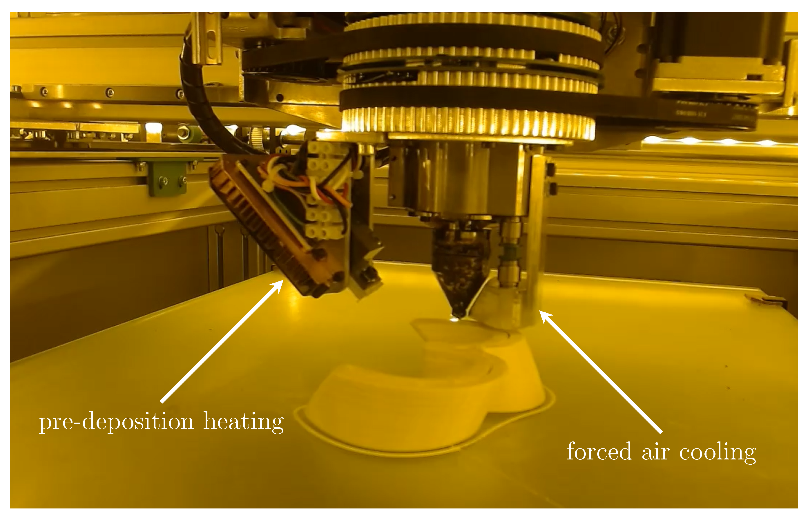
A print head as well as an extended machine control are presented, which enable process-oriented local laser pre-deposition heating (LLPH) and forced air cooling simultaneously. Two additional rotary axes on the printhead allow the two-dimensional application of pre- and post-deposition modifications in the FLM-process; compare Figure 1. Furthermore, its influence on the processing of semi-crystalline polypropylene is investigated.

2. Materials and Methods

To improve the process abilities by pre- and post-deposition treatments a rotary print-head was developed. In the following, the design and the application of the printhead are explained. This will be followed by a discussion of the component adhesion on the print bed and the experimental procedures.

2.1. Construction

The rotary print-head developed in this work has the ability to guide a LLPH-module on one rotary axis and a forced air cooler via compressed air on a second. Thus, this printhead enabled the integration of pre- and post-deposition process modifications; compare Figure 1.
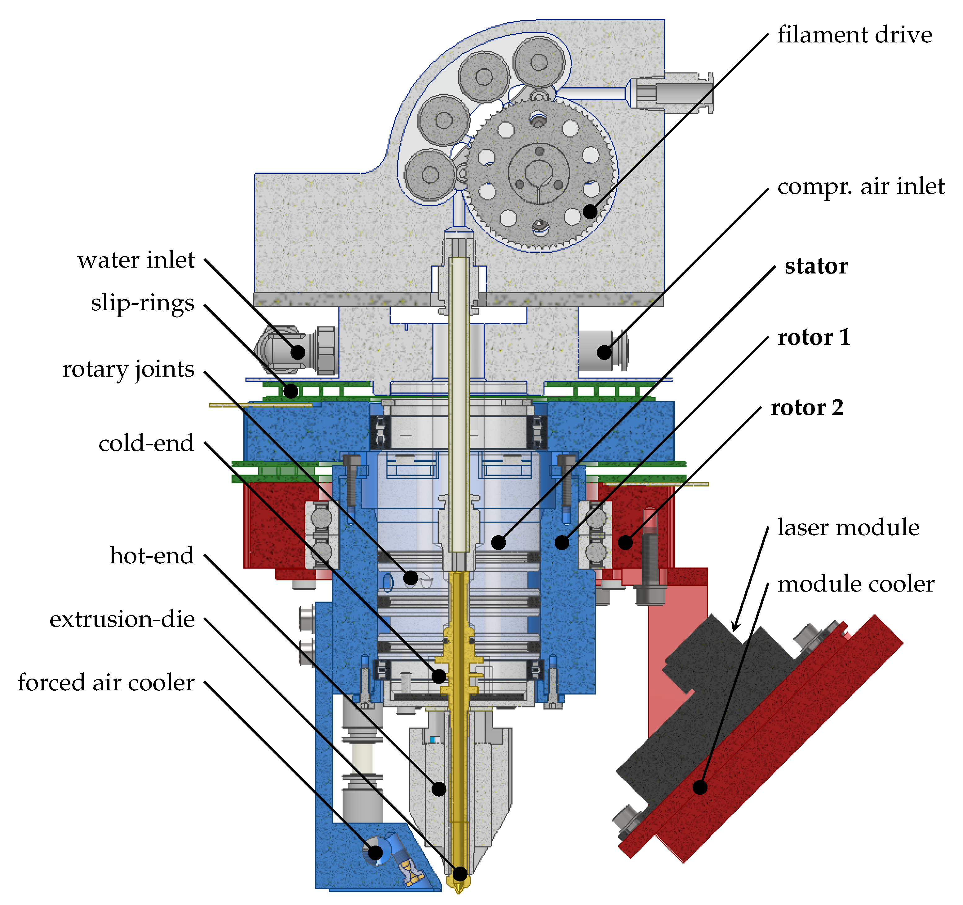
As shown in the cross-sectional view in Figure 2 the inner stator of the construction included the filament drive, the water cooled cold end, the hot end, as well as the connections for cooling water, compressed air, and electrical wiring. The first rotor guided the cooling module. In this approach, the cooler was realized as an open compressed air cooler, even if the design allowed a closed liquid cooling with in- and outlet through a rotary joint system. The forced air cooler operated with a pressure of 0.28 bar. Compressed air expanded via a nozzle with a bore diameter of 0.65 mm. As the first rotor was mounted on the stator, rotor 2 was mounted on rotor 1 with ball bearings and guided the laser module centered around the extruder. The laser module had a 6 W laser diode with a wavelength of 445 nm and an adjustable focusing lens. Based on the feed rate of the printhead the laser power was scaled, so that 100% of the nominal power was delivered at a speed of 60 mm s 1 . The module was cooled down by a Peltier element in conjunction with a convection cooler. To supply the laser module, two pancake slip-rings with eight contacts each connected the second rotor electrically with the stator. The rotors were driven by powerful Nema 24 stepper motors via a HTD-belt gear system, enabling high rotational accelerations, up to 15,000 ° s 2 . The necessity of high rotational accelerations was assumed in order to maintain the dynamic of the original process on the one hand and a homogeneous utilization of all drives as well as economical process speeds on the other hand.
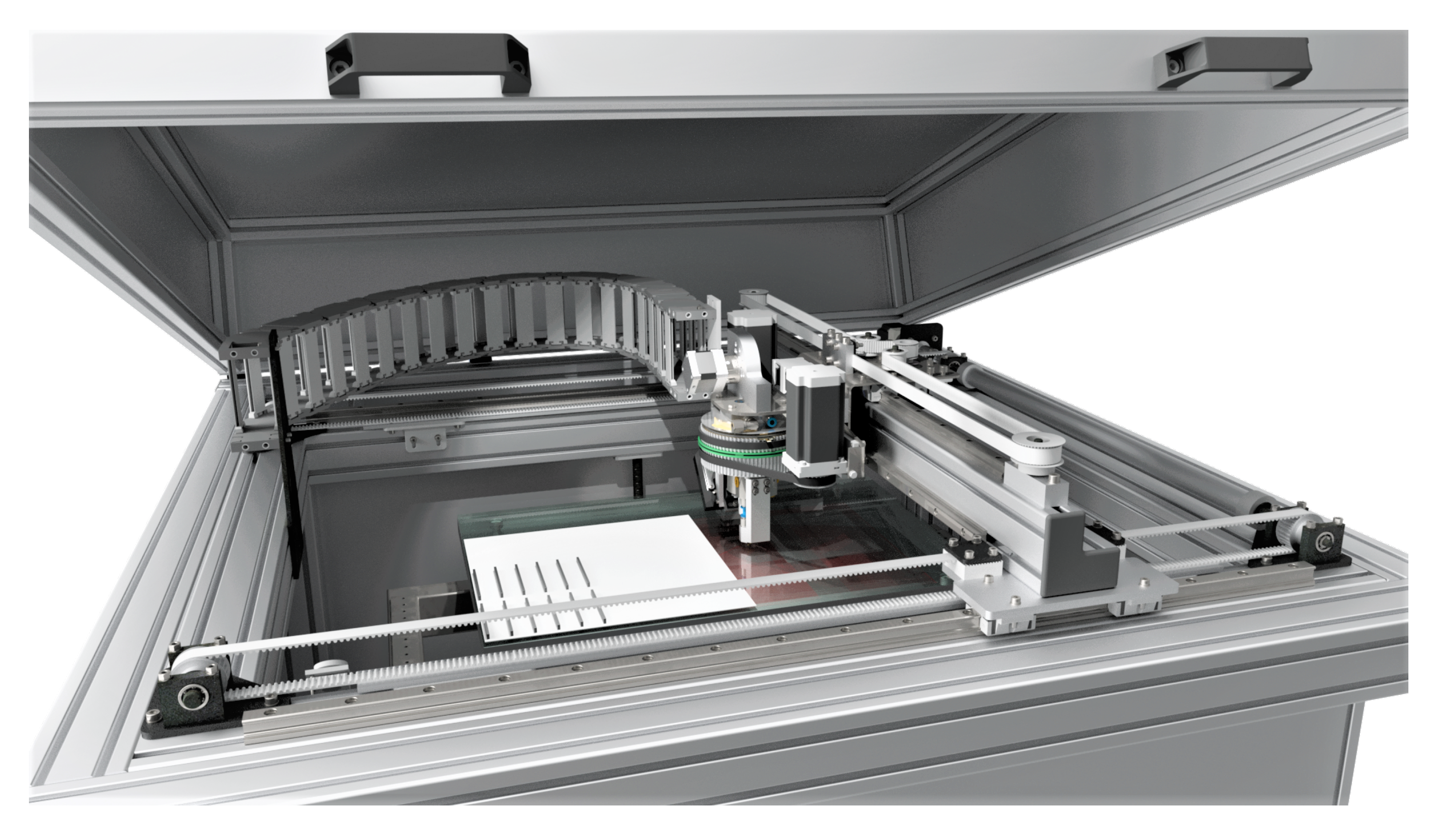
The modified process with its increased handling weights and laser radiation exposure necessitated the development and construction of an improved MEX test system, illustrated in Figure 3. A large build platform of 400 mm × 300 mm allowed samples to be positioned with generous spacing to favor comparable temperature distributions. The kinematics featured stable profile rail guides and Nema 24 motors with gearboxes to ensure precise positioning of the heavy printhead ( 13 k g ). The proposed design allowed additional measurement and process technology to be mounted on the axes. An anodized aluminum enclosure protected the operators from radiation. To enable process monitoring despite the enclosure, a camera was installed in the build chamber. Due to the high intensity of the reflected scattered radiation from the laser, an optical filter was added to make the process visible, see Figure 1.

2.2. G-Code Modification and Numerical Control

For the G-code generation of components to be manufactured the slicing software Cura was used. However, slicers such as Cura, applied adjustable optimization algorithms with respect to manufacturing time, optical part quality and strength, which could negatively affect the comparability of specimens. Therefore, the G-codes of specimens were generated by a python script that ensured comparable production conditions for all samples, illustrated in 
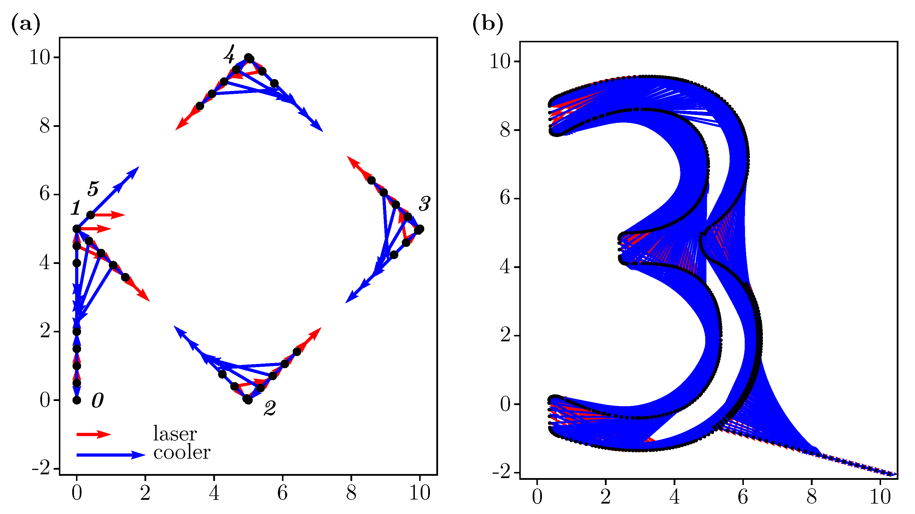
Figure 4. A second python script manipulated the G-code for the application of the rotary axes. It extended the existing axis commands with the additional rotational axes and added as many lines as needed in order to run the rotations with the specified resolution, as illustrated in Figure 5a,b. Figure 5a shows the systematic workflow of the script on the basis of an example geometry. Here, the G-code of five lines which embody a diamond shape, was extended to completely resolve the axis movement of the leading and trailing rotatory axes in the corner points. Depending on the given motion resolution as well as the relative distances of the laser and the cooling from the extruder, the G-code was altered by adding intermediate points shown as black dots. The red and blue arrows represent the angle and the distance of the laser and cooler relative to the extruder, oriented to the estimated contour. In all considered cases, the script ran stable. It was tested for a 20 h print with a final resolution of 0.1   m m . In this example, the G-code was extended from 5 MB up to 250 MB depending on the initial geometry and final resolution.
As numerical control the open source CNC controller LinuxCNC in combination with Mesa-Cards 5i25 and 7i76 was tested initially. The available motion-planning of Linux-CNC was limited to three axes, resulting in a stuttering process for 5-axis-motions. Therefore a commercial multiple axis CNC-control TwinCAT CNC by Beckhoff Automation GmbH & Co. KG (Verl, Germany) with an extended motion planning was acquired and adapted to this modified FLM-process.

2.3. Adhesion Strategy

As mentioned in Section 1, the influence of local laser pre-deposition heating and forced air cooling was investigated regarding its influence on warpage and interlayer bonding of PP. With respect to interlayer strength it is known that FLM-manufactured components exhibit anisotropic component properties and that this manifests itself with a reduction in strength mainly in the direction of construction (usually z-axis) [2,43]. Accordingly, tensile specimens were fabricated to determine the tensile strength in the z-direction.
Moreover, the usability of PP in MEX processes is limited by high residual stresses and the resulting component distortion. In order to be able to investigate the process- and material-related residual stresses on a macroscopic level, a printing strategy had to be developed which allowed the production of comparable specimen geometries. Due to the layer-by-layer deposition typical for MEX processes, this required the complete elimination of in-process warping. Accordingly, warping also had to be completely prevented for the maximum expected residual stresses by the adhesion of the material to the print bed [7]. Thereby, the poor print bed adhesion of PP is a well-studied problem. Widely used building platforms only allow weak adhesion in combination with PP. Even approaches such as varying bed and die temperature, as well as layer cross-section and printing speed do not provide sufficient adhesion [17,18]. In their publication, Spoerk et al. summarize a series of scientific papers dealing with different build platforms for PP. Promising results in optimizing the adhesion of PP are found mainly for films and sheets made of the same material. It must be taken into account that, depending on the process conditions, the filament tends to weld to the build platform, which on the one hand makes it more difficult to detach the finished component and on the other hand reduces the durability of the build platform. Spoerk et al. also investigate whether thermoplastics with similar chemical compositions to PP are suitable as build platform materials. They find that polyethylene (PE) as a building platform has similar adhesion properties to PP as common pairings of platforms and extrusion material [7,18].
As mentioned, warping had to be completely prevented in order to analyze residual stresses by measuring distortion. Therefore, an alternative printing strategy was developed. A raft of glycol-modified polyethylene terephthalate (PET-G) was printed onto a glass building platform in conjunction with an adhesion promoter. The good adhesion of the PET-G to the platform in combination with the large surface area resulted in a resilient bond. The raft was provided with an open surface structure. Afterwards, the PP component was printed with reduced spacing on top of the open raft structure, resulting in an interlocking mechanical connection between the rafts open surface and the bottom layer of the component. By setting the process parameters the properties of the joint were adjusted, resulting in a heavy duty joint preventing in-process warping.

2.4. Experimental Procedure for Distortion Measurement

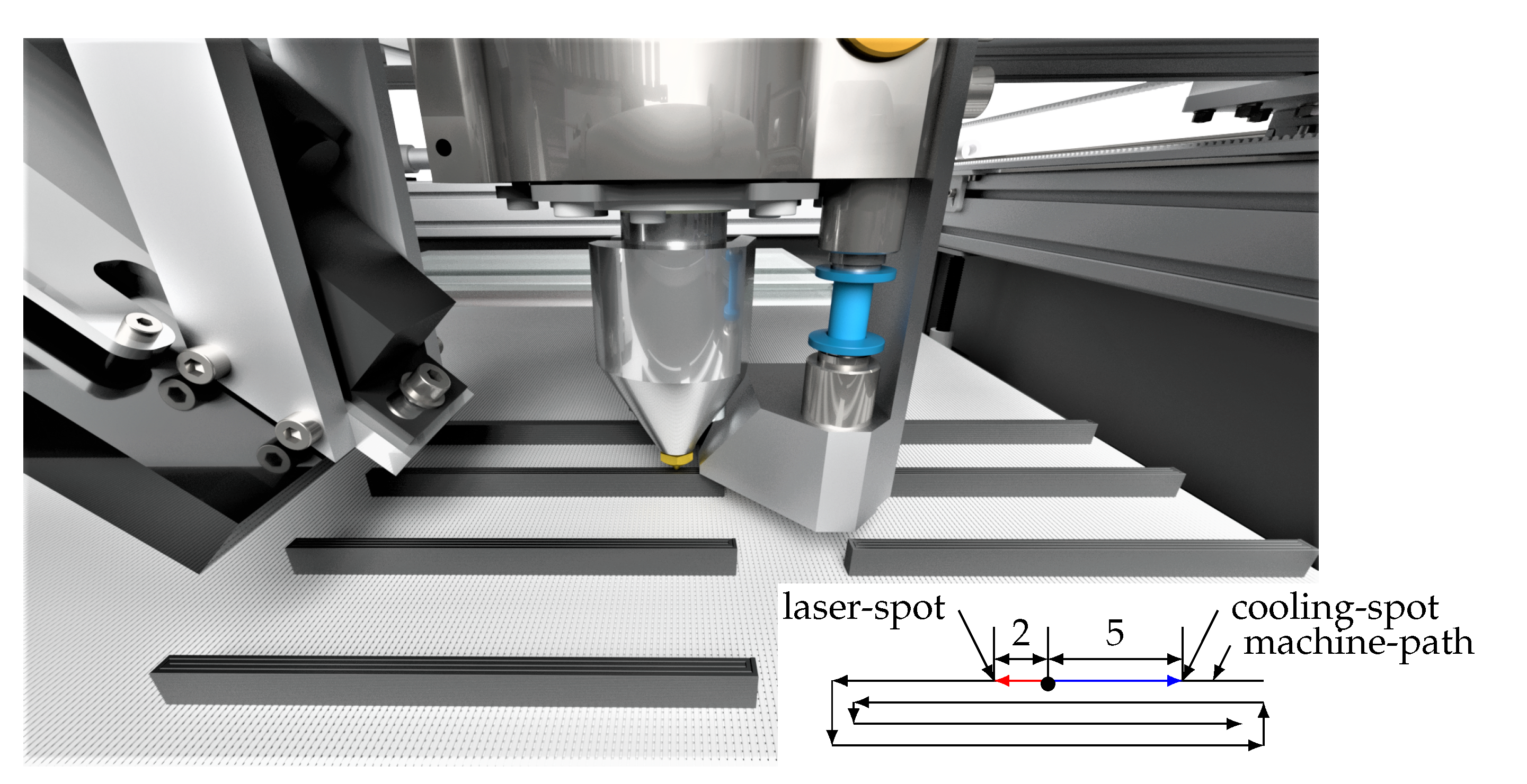
In order to investigate the influence of local laser preheating and forced cooling on the part distortion, a full factorial experimental design was used. Screening tests had shown that different feed rates, print bed temperatures as well as layer dimensions in combination with changing die temperatures had a negative influence on the sample quality with regard to their comparability. Unlike the die temperature, these parameters had shown little influence on warpage. Therefore, the test plan was limited to the parameters die temperature, laser power as well as cooling influence. The remaining parameters were set to constant values, compare Table 1 and Table 2, that were appropriate for the MEX process and allowed a wide parameter range. The distances between the extrusion die and the laser-spot, as well as the cooling nozzle were adjusted to 2 m m and 5 m m respectively; compare Figure 4. Bed temperature was set at 75 ° C , which ensured optimal adhesion of the raft. The environmental temperature between 25 ° C and 27 ° C was measured during the tests and was attributed to the closed build chamber. Before the Design of Experiments was developed, the process limits were determined. With a laser power of 2500 m W , macroscopic decomposition phenomena of the plastic could be detected. Therefore, the maximum laser power was limited to 2500 m W . The operating pressure of the forced air cooler was limited. For pressures above 0.28 bar the kinetic energy of the air stream influenced melt deposition resulting in macroscopic defects of the specimens. The die temperature was investigated in the range of 175 ° C and 250 ° C , since below 175 ° C increased viscosities led to insufficient extrusion, and above 250 ° C material degeneration began. For extrusion temperature, the levels 175 ° C , 187.5   ° C , 200 ° C , 225 ° C and 250 ° C were chosen. The intermediate step 187.5   ° C was additionally selected, since preliminary tests have shown promising results for low extrusion temperatures. For the applied laser power the steps 0 m W , 500 m W , 1000 m W , 1500 m W , 2000 m W were selected in order to map the influence of the laser power. With respect to the distortion samples, data also was collected for 2500 m W of laser power. These were only considered for the distortion study. Forced air cooling was only tested by activating or deactivating the cooler with an operating pressure of 0.28 bar. This categorical parameter was chosen to show whether cooling had a significant influence on the process. In future studies, the influence of local cooling must be evaluated as a function of its cooling rate in order to characterize its effect in more detail. For both distortion and tensile strength studies, specimens with the same die temperature were fabricated in one process to prevent component heating; compare Figure 4. The result of the Design of Experiment can be found in Table 3.
The deformation of printed specimens was investigated in order to quantitatively evaluate the residual stresses of components. Since the distortion of the specimens was prevented during the process, only distortion due to residual stresses of the final part, after detaching it from the print bed, was evaluated. The dimensions of the specimens also had to be approximated in preliminary tests. With increasing specimen length, the absolute distortion became larger. This favored the measurement of the specimens, but hindered their fabrication. Accordingly, the specimen dimensions were selected in such a way that in-process warping could be completely prevented and yet a macroscopically measurable distortion resulted. Specimens with the dimensions 80 mm × 3 mm × 6 mm were printed as two perimeters according to the custom script, compare with the machine path in 
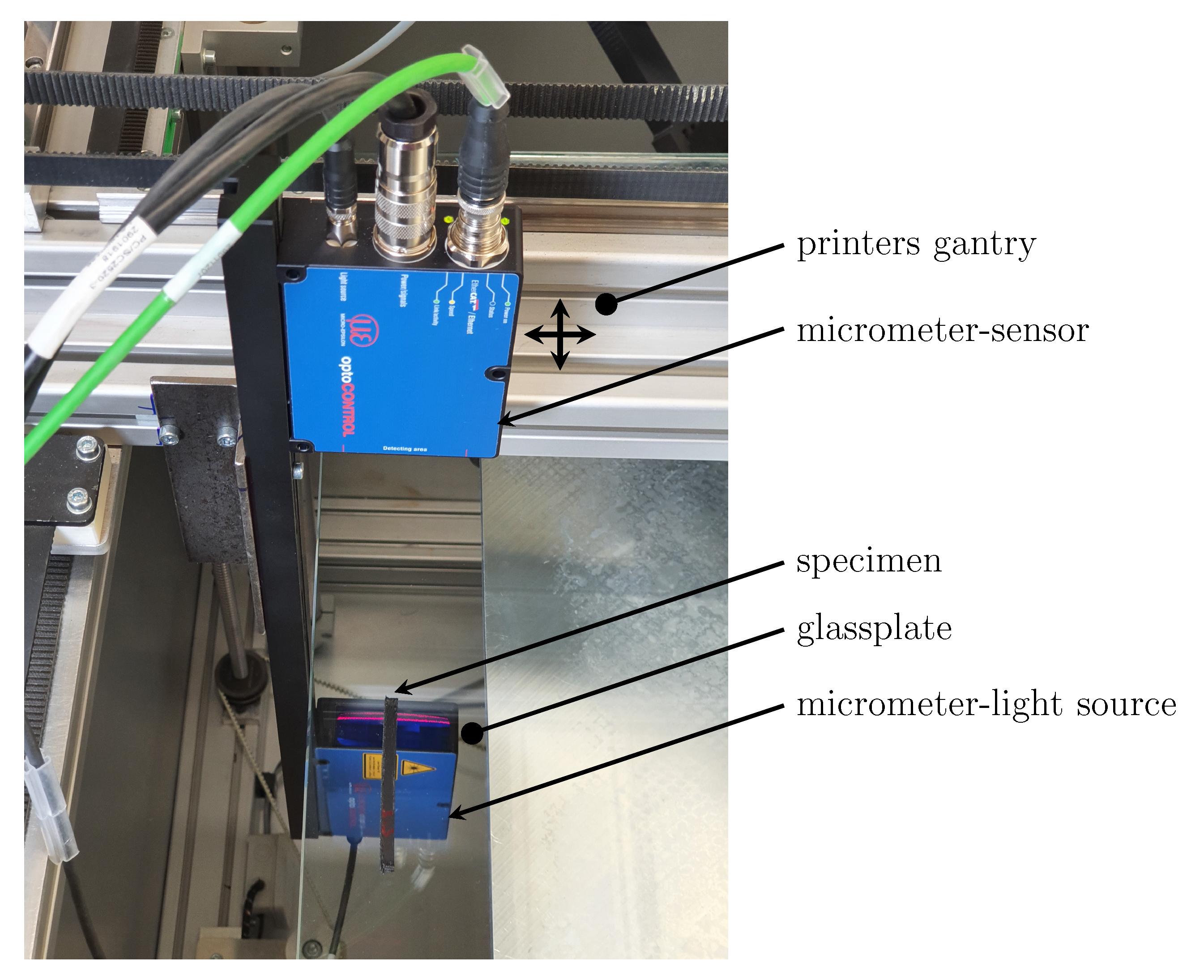
Figure 4. After production of the specimens, they were immediately removed from the print bed. Tactile measurement of the specimens was almost impossible due to their low mechanical stiffness. Therefore an optical measurement strategy was developed to measure the cross-section of the specimens through a glass plate. A digital optical precision micrometer (Micro-Epsilon, optoCONTROL-2520-46) was used, which, as can be seen in Figure 6, was mounted on the x-axis of the printer. During a constant traverse of the x-axis, the upper and lower specimen profile was recorded with an appropriate resolution of 100 measurements per m m .
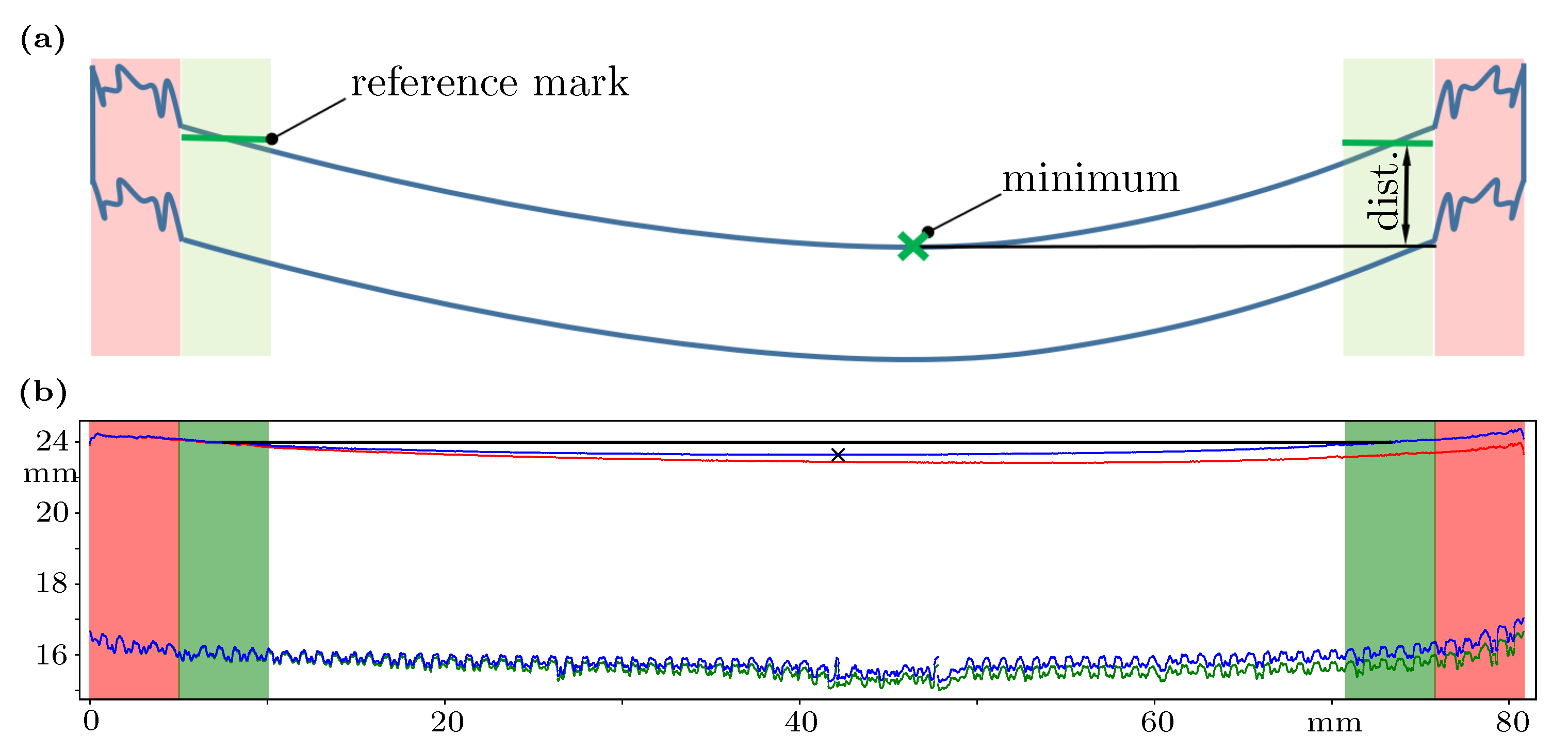
Figure 7a shows the method of digital preparation and evaluation of the measurement data. Since FLM components and specimens show different degrees of errors depending on the variation of process parameters, which occur preferably at corners and component ends, the evaluation of these areas can lead to high scattering of the measured data. For this reason, the boundary areas of the specimens, highlighted in red with a width of 5 m m , was excluded from the automated evaluation.
Different evaluation methods were investigated with respect to warpage. In this work, the warpage was evaluated using the difference between the value of the reference marks and the minimum of the upper contour, which allowed a quantitative evaluation of the component deformation and thus the residual stresses accumulated in the process.
Due to the individual specimen shapes, no mechanical alignment for measurement could be performed. Angular alignment errors of the specimen on the glass plate were therefore corrected algorithmically. In order to make the automatic evaluation more robust against measurement errors and local sample errors, averaged reference marks were determined at the sample ends. The measured values of the upper edge in the green highlighted areas, 5 to 10 mm from the specimen ends, were averaged for this purpose. Using these reference marks, the angular misalignment was corrected, resulting in the specimen geometry shown in blue.
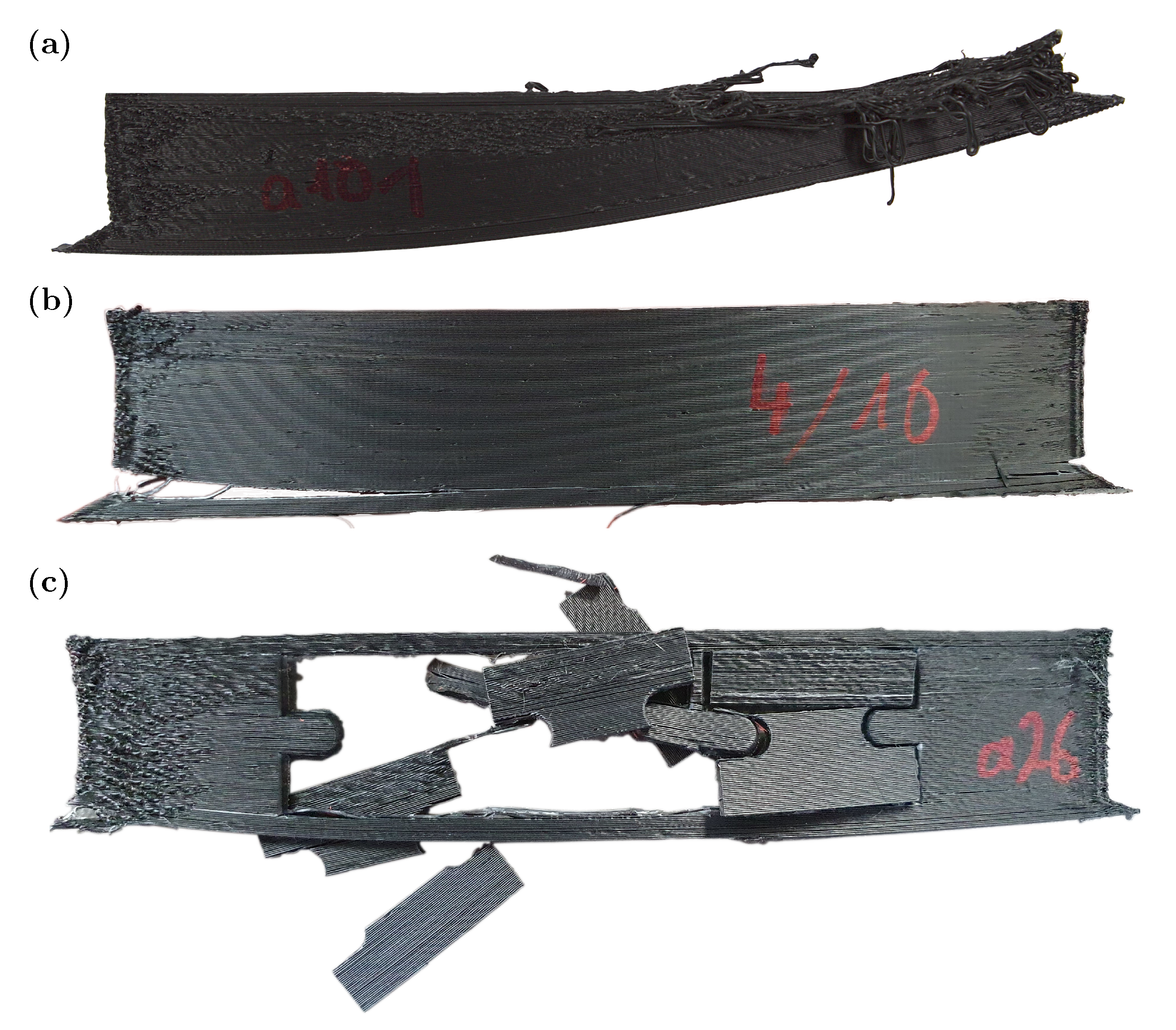
As an example, the detected geometry of a specimen is shown in Figure 7b. The red contour represents the measured upper edge, the green contour the lower edge of the specimen. The lower green edge has interfering contours due to the interaction with the raft and can therefore not be used for the evaluation of warpage. Because of the suppression of in-process warpage and the 2.5-dimensional manufacturing process, the component top edge is suitable for evaluating distortion. The difference between the measured reference mark and the minimum is chosen as measure of in-process warpage. As mentioned at the beginning of Section 2.3 the in-process warping had to be prevented to produce valid samples. If the specimen warped during the process, the specimens height at its ends decreased, which could be detected by the measurement, so that invalid sample preparations were excluded from the evaluation.

2.5. Experimental Procedure for Interlayer Bonding Measurement

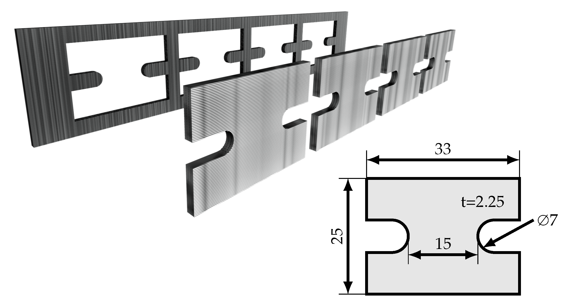
The fabrication of tensile specimens in the z-direction was problematic. Both the large component height and the small cross-section of the typical specimen geometries such as those according to I S O 527 2 caused large flaws during the transient manufacturing process. In order to increase the comparability of the specimens, large cross-section blanks were printed, from which specimens were cut out using a punching knife. Due to the lower height in the z-direction and the large width of the specimen blank ( 180 mm × 40 mm × 2.25   mm ), the process was stabilized and extrusion errors were effectively eliminated.
The specimen geometry was characterized by the dimensions 25 mm × 35 mm × 2.25   mm as well as a test cross-section of 15 m m × 2.25   m m which was provided by two notches in the punching knife; compare Figure 8. The short specimen length was chosen because it had significantly shortened the manufacturing time the specimens. Thus, no determination of the Young’s modulus could be made. Further, it was not easy to determine standard-compliant strength values, since the notch effect in the test area influenced the specimen strength. Consequently, the calculated stresses had to be evaluated as an approximation of the absolute strength, but could be compared relatively with each other in order to evaluate the interlayer strength quantitatively.
Due to the significantly larger dimensions of the tensile specimen blanks, higher demands were placed on component adhesion than with the specimens which were produced to investigate warpage. Figure 9a shows a sample with excessive warping due to inappropriately chosen interface parameters. For this reason, the specimen blanks were extended by a chamfer and a brim to increase the contact area and reduce the peak-stress in the interface; compare Figure 9. The specimens were tested using a GALDABINI Quasar 25 k N material testing machine additionally equipped with a HBM U10 force transducer with a capacity of 2.5   k N .

3. Results

The results, shown in Table 3, were statistically analyzed with the data analysis tool JMP by ©2021 SAS Institute Inc. (Cary, USA). Afterwards, the data was processed and visualized in Matlab2020 software by The MathWorks, Inc. (Natick, USA). In this chapter, the influence of component distortion and process-related residual stresses is investigated, followed by an analysis of the interlayer bonding. Finally, the results are combined and the effect of pre-deposition heating and Forced air cooling on the processing of PP is evaluated.

3.1. Residual Stresses

As shown by the influence residuals in Figure 10, extrusion temperature, applied laser power, and forced air cooling were identified as significant linear influences on warpage. No statistical significance could be determined for interactions and higher order influences. As already mentioned in Section 2.4 process-relevant parameters, such as the feed rate, the print bed temperature or the layer cross-section were not varied.
Figure 11 illustrates the measured values of Table 3 and as well as linear curve fits versus the influencing factors die temperature and laser power. To emphasize the effect of cooling, the results with activated forced air cooling are shown in blue and those without are shown in red. The lower plane represents the linear fit of the experimental results with activated forced air cooling (blue marks, R 2 = 0.85 ), while the upper plane depicts the results without forced air cooling (red marks, R 2 = 0.86 ). According to the statistical evaluation, neither the introduced laser power nor the temperature interacted with the forced air cooling. This relation is represented by an approximate parallelism of the fitted planes. The forced air cooling reduced the distortion by an average of Δ d i s t ¯ c o o l i n g =   0.084   m m . Depending on the extrusion temperature and the laser power, this corresponded to a reduction of 22.3–55.8%. Both Figure 10 and Figure 11 show that cooling had an inhibitory effect on warpage and thus appeared to reduce the residual stresses in the components.
Likewise, warpage was reduced for low extrusion temperatures and low laser powers. Minor warpage of 0.161   m m could be achieved even without forced air cooling. At high temperatures and laser powers, on the other hand, warpage was in the magnitude of 0.349   m m , compare Table 3. The varied die temperature had a higher impact on warpage than the laser power; compare Figure 10 and Figure 11.

3.2. Interlayer Bonding

The scope of the experiments was limited by the process parameters, the material properties and the test methods, as described in Section 2.4 and Section 2.5. In addition, the investigations on tensile stress revealed that high extrusion temperatures (>250 ° C ) led to high resulting residual stresses which overcame the interlayer bond and broke the sample blank as shown in Figure 9b. For particularly low extrusion temperatures (>175 ° C ) and low laser powers, the applied forces of the punching knife led to the destruction of the specimens due to poor interlayer bonding; compare Figure 9c.
The test plan was based on these process limits, but included the tests at 175 ° C extrusion temperature to reflect the effect of pre-deposition heating at low extrusion temperatures. Therefore, no tensile strengths could be determined for low extrusion temperatures without additional pre-deposition heating, compare Table 3. The low process energy did not support a stable fusion process of the layers, resulting in brittle specimen with highly fluctuating layer bonding. Therefore invalid tensile tests were excluded from the evaluation of the interlayer bonding if tensile strength fell below 5 M Pa or the coefficient of variance was above C V > 0.15 . Excluded tests are marked gray. The sample count refers to the number of valid tensile-tests, compare Table 3.
Statistical evaluation of the tensile tests showed that forced air cooling had no significant influence on interlayer bonding, because the p-value of 0.056 was above the significance level of 0.05 and the coefficient of determination ( R c o r r 2 = 0.0062 ) of the linear influence on strength was very low. This conclusion, which is in contradiction with previous research, is discussed in Section 4. Higher order influences of laser power and die temperature were identified to have a significant effect on interlayer bonding. Based on this evaluation, the polynomial model, shown in Figure 12, was fitted.
The extrusion temperature had a cubic influence on the interlayer bonding. As highlighted in Section 1, low extrusion temperatures led to poor interlayer diffusion and, therefore, low strengths in the z-direction. Without an additional heat input, the necessary energy for the fusion of the strands had to be provided by the heat capacity of the deposited melt strand. In contrast, extrusion temperatures above a certain treshold led to thermal damage of the material, so that its mechanical properties were degraded. With respect to the extrusion temperature, a maximum of the strength in the z-direction was obtained for 220 °C to 240 °C; compare Figure 12.
Pre-deposition heating in form of laser radiation raised the temperature of the cool substrate locally, thereby increasing the average temperature of the deposition process. This promoted interlayer diffusion without increasing the absolute melt temperature. Consequently, the average temperature of the deposition process was raised without reaching thermal degradation. For the laser power, cubic influences on the strength could be found. Maximum strength turned out for medium laser powers of about 900 mW to 1500 mW; compare Figure 12. Higher values of introduced radiation (>1500 mW) caused material degradation in the surface area of the substrate, which negatively influenced interlayer bonding. Forced air cooling as an effect is not plotted in Figure 12 and Figure 13 due to its lack of significance.
The fitted model achieves a corrected coefficient of determination of R 2 corr = 0.8151 . Measured by the transient MEX-process, its variety of influencing parameters and interferences as well as limited investigation possibilities, the model plausibly explained the influence of die temperature and laser power on interlayer bonding. The deviation of the model could be explained by the high scatter of the test results, which can be attributed to the previously mentioned factors.

3.3. Consolidated Influence of Process Modifications on Residual Stresses and Interlayer Bonding

After giving an overview of the effects of pre-deposition heating, as well as subsequent forced air cooling on the distortion (Figure 11) and strength in the z-direction (Figure 12), the results presented were combined to show the optimization goals with respect to both target variables; compare Figure 13 and Figure 14.
In consistency with the distortion diagram; compare Figure 11, active cooling is indicated by blue markings. Figure 13 shows the potential for optimization in terms of strength and distortion. In this contour plot, the minimal distortion is shown implicitly in form of the blue line. It is determined with the following computational procedure:
(1)
The datasets for both the distortion and tensile strength are interpolated on an identical meshgrid with a resolution of 0.5   ° C for die temperatures and 5 m W for laser powers
(2)
Let σ be the corresponding two dimensional array of tensile strengths for given die temperatures a and laser powers b, rounded to the first decimal digit. Define σ ˜ as the one dimensional array which lists all unique entries of σ in ascending order
(3)
Iterate over the length of σ ˜ with variable i:
(a)
Determine all tuples ( a j , b j ) , such that σ ( a j , b j ) = σ ˜ ( i )
(b)
Return the tuple ( a , b ) out of the set of ( a j , b j ) for which distortion is minimal
Thus, the blue line contains combinations of values for die temperature and laser power for which distortion is minimal at a given tensile strength. It has already been established that the component strength in the z-direction showed a maximum for moderate extrusion temperatures and laser powers. Since the distortion increased linearly with respect to these variables (compare Figure 11), a range of reasonable process parameters up to moderate extrusion temperatures and laser powers resulted, shown as a dashed rectangle (compare Figure 13). All points outside this range represented a poor compromise between achievable strength and distortion, especially since degradation of the material could be expected.
The black mark in Figure 13 and Figure 14 at 232.5   ° C without additional laser power and cooling, represents the point of maximum achievable strength for the FLM process without modifications. Without process modifications, the model-based distortion was 0.282   m m with a strength of 12.6   M Pa . Less warpage could only be achieved by reducing the extrusion temperature; compare Figure 11. This was accompanied by a considerable reduction in strength, shown by the black line in Figure 13. To illustrate this relationship, the data of the distortion (Figure 11) and the strength (Figure 12) were combined in Figure 14. With the presented process modifications of LLPH and subsequent forced air cooling, the limits of the process window could be shifted considerably. Beneficial parameters for the process modifications are highlighted in blue; compare Figure 13 and Figure 14. According to the test results (Figure 12 and Figure 13), the additional cooling did not affect tensile strength, but reduced warpage to a considerable extent. This effect of cooling can be seen by the nearly constant shift of the data points in Figure 14. With an additional laser power of 1170 mW and a die temperature of 222 °C the tensile strength could be increased by 13% to 14.2 MPa, highlighted by the blue point in Figure 13. Forced air cooling could reduce the warpage simultaneously by 30% to 0.198 mm. If the optimization goal of minimal warpage due to component residual stresses was pursued (marked with a blue diamond), comparable strengths (12.6 MPa) could be achieved at a lower die temperature of 189 °C and additional LLPH of 1240 mW; compare Figure 13. Due to the low extrusion temperature and the activated forced air cooling, a reduction of distortion by 55% to 0.126 mm was achieved. The missing thermal energy due to the low extrusion temperature was compensated by the introduced laser radiation and the component strength was not negatively affected.

4. Discussion

In this paper, a rotary print head is presented. This head allowed fully integrated pre- and post-deposition process modifications of the FLM-process. A laser radiation source and a forced air cooler, each guided on a rotational axis, supplied additional local heat input and output to the FLM deposition process. The results presented show that the process modifications had considerable influence on the processing of PP. For this purpose, samples with and without process modifications were compared.
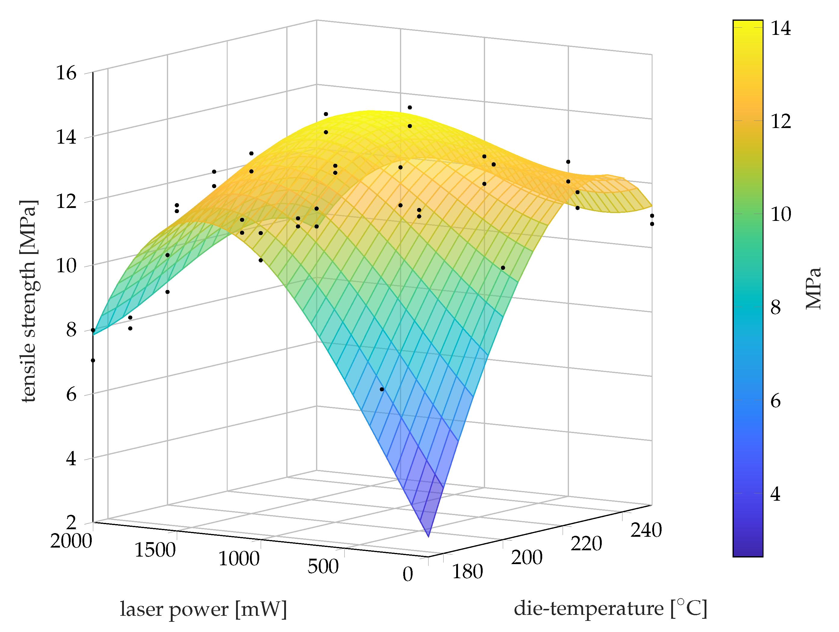
Through tensile tests on printed PP specimens, interlayer bonding was investigated. Comparable to the research of Despande et al. and Ravi et al. for ABS, and Han et al. for PEEK, it was shown that the strength in the build-up direction (z-axis) of PP was positively influenced by additional local laser preheating of the substrate [34,35,36,37,39,41]. Further research is needed to characterize the influence of LLPH on interlayer bonding. Analytical approaches emphasize that preheating of the substrate promotes interlayer bonding. For example, McIlroy et al. found that elevated temperatures accelerate diffusion in the FLM process [44]. This relationship plays an important role for semi-crystalline thermoplastics, since most of the diffusion takes place above the melting temperature and proceeds more rapidly [21]. For PP, Petersmann et al. found that an elevated die temperature and thus welding temperature results in a higher degree of interlayer diffusion [22]. Both the tensile strength studies presented and prior research underline that LLPH favors the interlayer bonding of PP. To further characterize the influence on interlayer bonding, morphological and further mechanical studies are necessary.
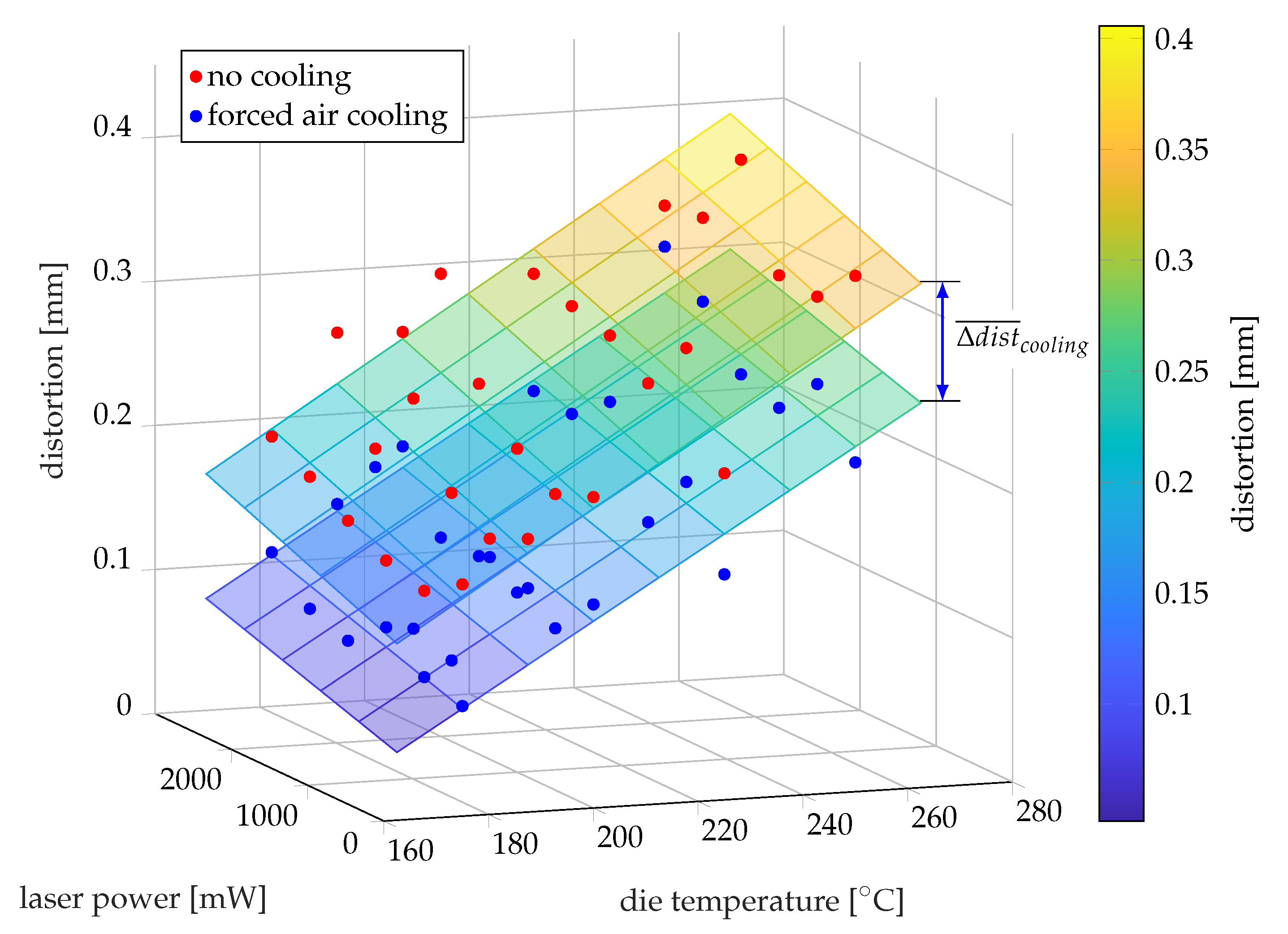
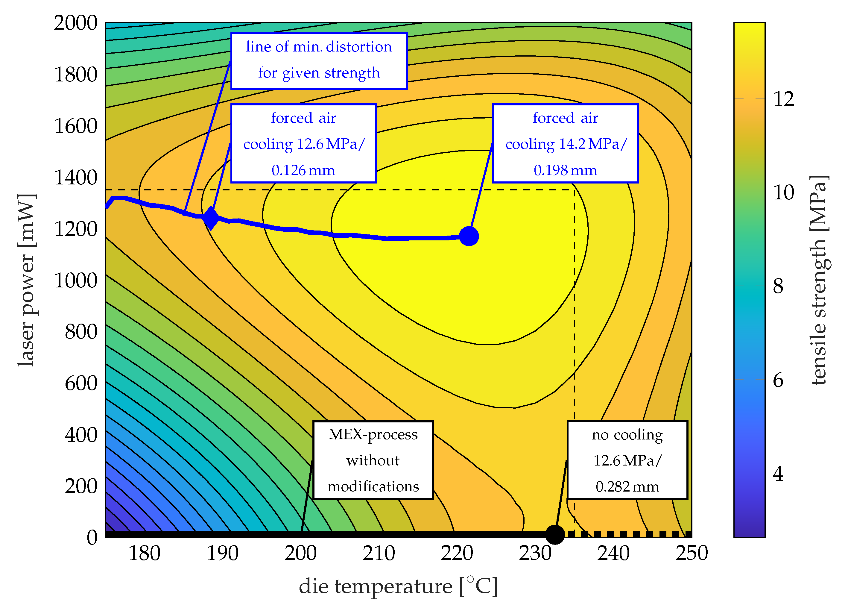
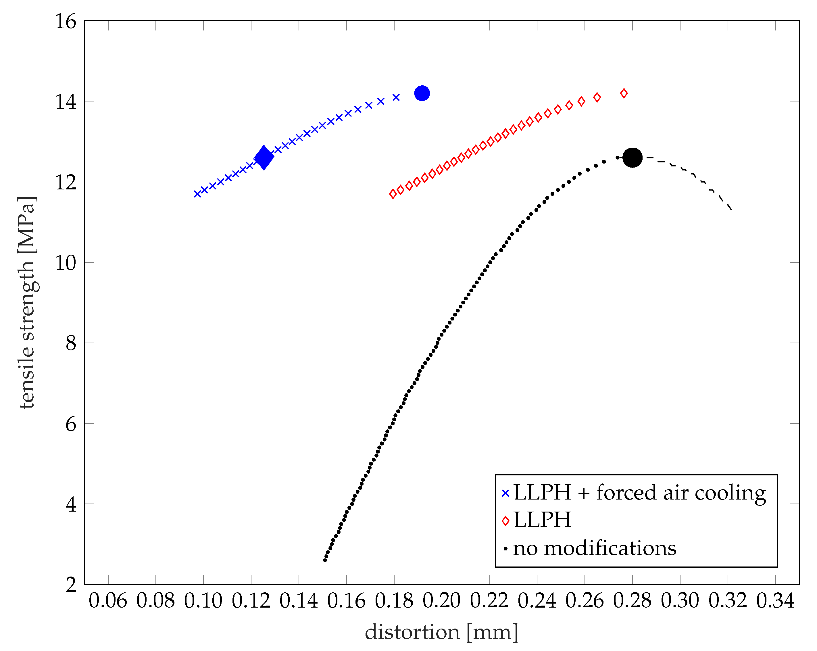
However, in this work, the LLPH-device could be fully integrated into the MEX process by a rotational print head. Additionally, a forced air cooler was combined with the LLPH-technology, which ensured a significant reduction in warping through a high local cooling rate without lowering the average component temperature. In parallel, the introduced laser power in conjunction with lower extrusion temperatures could achieve an additional reduction in warpage while maintaining the component strength. Compared with the state-of-the-art, it was shown that process parameters such as the die temperature could be adjusted in conjunction with process modifications in such a manner that component strength was increased and residual stresses were reduced [19,26,27]. In order to investigate the influences of the modifications on the process and the processing of semi-crystalline thermoplastics, a set of parameters typical of the process were selected and kept constant throughout the experimental plan. In this way, the effects of the modifications were adequately demonstrated.
Due to the high number of non-varied process parameters, no interactions of LLPH and forced air cooling with other parameters could be investigated, besides die temperature. The hypothesis derived in Section 1 that cooling rate reduces the development of residual stresses and the resulting warpage was proven in the investigations shown. Whether the morphology of PP is affected as suspected needs to be investigated.
In contrast to prior research, an influence of the cooling rate on interlayer strength was not found for PP [25,45]. Geng et al. and Lee et al. used thermography to monitor the component temperature during the process and found that the component temperature is significantly above the ambient temperature without additional cooling. It is assumed that the specimens were fabricated individually and, therefore, the component temperature was elevated due to short layer and cooling times. High temperature favors interlayer diffusion, but can have a negative effect on surface quality, which is why component coolers have become established in the FLM process. In this work, the samples for the investigation of interlayer bonding were fabricated in parallel. Due to the resulting high layer and cooling time, it can be assumed that the influence of local cooling on the average temperature of these samples and thus the interlayer bonding was low. To the best of the authors’ knowledge, no study has been published that addresses the influence of local cooling of the deposited strand on interlayer bonding. In general, interlayer diffusion depends on the temperature and time of the welding process. For semi-crystalline thermoplastics, significant diffusion occurs above the melt temperature [21,46,47]. For the present study, it is assumed that heat conduction and melting of the substrate dominates the rapid cooling of the interface and limits the diffusion time. This would explain why no significant effect of forced air cooling on interlayer bonding could be found in this study. Nevertheless, local cooling can be expected to influence interlayer bonding for other process parameters, component dimensions, and materials.
In future work, the scope of the experiments can be extended to include a variation of parameters identified as relevant by prior research. These include, for example, the print bed temperature [27], the layer cross-section [19,28] or the printing speed [28]. The variation of the cooling rate has not been investigated and needs to be addressed in future research.
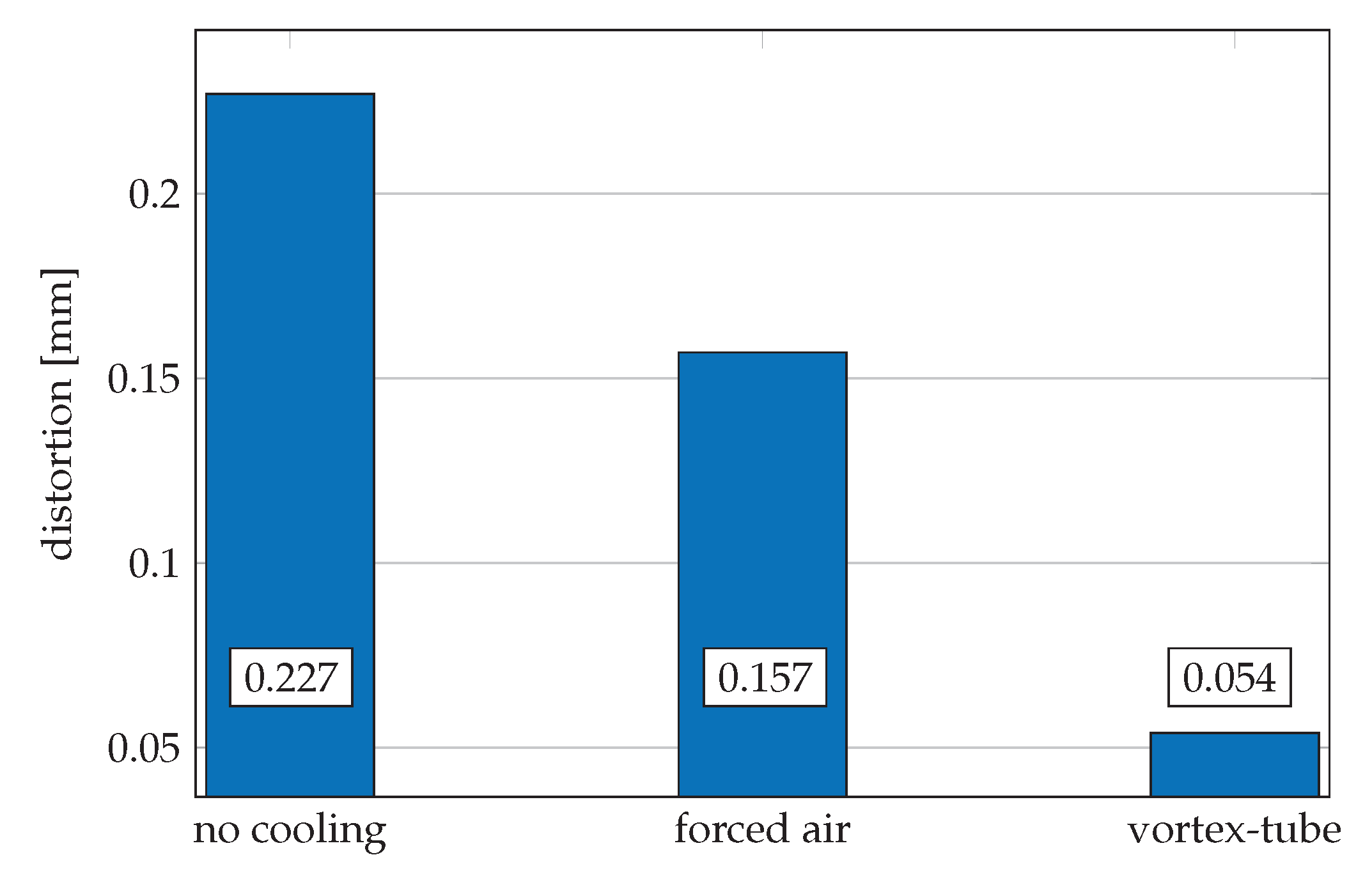
As an outlook, a preliminary test was carried out. The cooling air temperature was reduced by means of a vortex tube, with which the component distortion could be further inhibited compared to the forced air cooling with compressed air; compare Figure 15. It was possible to reduce the distortion of a sample by another 65% via a reduced cooling air temperature compared to compressed air. Even though the result of this test can only be evaluated qualitatively and without its impact on interlayer strength, the potential of further research is nevertheless presented.
The semi-crystalline thermoplastic PP has valuable mechanical properties, but can only be processed to a very limited extent, because of high residual stresses and poor strength in the z-direction. It was shown that both interlayer bonding and warping could be positively influenced by the process modifications, shown. In particular, the limiting property of warping [7] is treated and reduced in terms of process technology instead of material science. By improving the layer bonding, the typical anisotropy of MEX-manufactured components can be additionally reduced. In future work, the modified process and its transferability to other semi-crystalline thermoplastics such as polyamide (PA) or polyethylene (PE) must be investigated in more detail. The comprehensive reduction of process-related residual stresses considerably extends the processability of semi-crystalline thermoplastics in the MEX process. The range of applications for MEX processes can be sustainably extended by further semi-crystalline thermoplastics in the material spectrum.

Author Contributions

Conceptualization, P.B.; methodology, P.B. and B.K.; software, P.B. and D.S.; validation, P.B.; formal analysis, P.B.; investigation, P.B.; resources, B.K.; data curation, P.B. and D.S.; writing—original draft preparation, P.B.; writing—review and editing, D.S. and B.K.; visualization, P.B. and D.S.; supervision, B.K. All authors have read and agreed to the published version of the manuscript.

Funding

This research was funded by BMWI (Bundesministerium für Wirtschaft und Energie ZIM program) grant number 2F4101113WO7.

Data Availability Statement

Data is contained within the article.

Acknowledgments

We gratefully acknowledge Tim Krautwald for his assistance in solving the specimen adhesion problem to the build platform. We also thank 3win GmbH for supporting in mechanical development and manufacturing.

Conflicts of Interest

The authors declare no conflict of interest.

Abbreviations

The following abbreviations are used in this manuscript:
FLMfused layer modeling
MEXmaterial extrusion
FDMfused deposition modeling
FFFfused filament fabrication
PLApolylactic acid
ABSacrylonitrile butadien styrene
PET-Gpolyethylene terephthalate glycol-modified
PPpolyproyplene
PPSpolyphenylene sulfide
PEEKpoly ether ether ketone
PEpolyethylene
PApolyamide
LLPHlocal laser pre-deposition heating
CNCcomputer numerical control

References

  1. Cuan-Urquizo, E.; Barocio, E.; Tejada-Ortigoza, V.; Pipes, R.B.; Rodriguez, C.A.; Roman-Flores, A. Characterization of the Mechanical Properties of FFF Structures and Materials: A Review on the Experimental, Computational and Theoretical Approaches. Materials 2019, 12, 895. [Google Scholar] [CrossRef] [PubMed] [Green Version]
  2. Gao, X.; Qi, S.; Kuang, X.; Su, Y.; Li, J.; Wang, D. Fused filament fabrication of polymer materials: A review of interlayer bond. Addit. Manuf. 2021, 37, 101658. [Google Scholar] [CrossRef]
  3. Turner, B.N.; Gold, S.A. A review of melt extrusion additive manufacturing processes: II. Materials, dimensional accuracy, and surface roughness. Rapid Prototyp. J. 2015, 21, 250–261. [Google Scholar] [CrossRef]
  4. Turner, B.N.; Strong, R.; Gold, S.A. A review of melt extrusion additive manufacturing processes: I. Process design and modeling. Rapid Prototyp. J. 2014, 20, 192–204. [Google Scholar] [CrossRef]
  5. Wohlers, T.; Campbell, R.I.; Diegel, O.; Huff, R.; Kowen, J. Wohlers Report 2020: 3D Printing and Additive Manufacturing State of the Industry; Wohlers Associates: Fort Collins, CO, USA, 2020. [Google Scholar]
  6. Das, A.; Chatham, C.A.; Fallon, J.J.; Zawaski, C.E.; Gilmer, E.L.; Williams, C.B.; Bortner, M.J. Current understanding and challenges in high temperature additive manufacturing of engineering thermoplastic polymers. Addit. Manuf. 2020, 34, 101218. [Google Scholar] [CrossRef]
  7. Spoerk, M.; Holzer, C.; Gonzalez-Gutierrez, J. Material extrusion–based additive manufacturing of polypropylene: A review on how to improve dimensional inaccuracy and warpage. J. Appl. Polym. Sci. 2020, 137, 48545. [Google Scholar] [CrossRef]
  8. Penumakala, P.K.; Santo, J.; Thomas, A. A critical review on the fused deposition modeling of thermoplastic polymer composites. Compos. Part B Eng. 2020, 201, 108336. [Google Scholar] [CrossRef]
  9. Spoerk, M.; Arbeiter, F.; Raguž, I.; Weingrill, G.; Fischinger, T.; Traxler, G.; Schuschnigg, S.; Cardon, L.; Holzer, C. Polypropylene Filled With Glass Spheres in Extrusion-Based Additive Manufacturing: Effect of Filler Size and Printing Chamber Temperature. Macromol. Mater. Eng. 2018, 303, 1800179. [Google Scholar] [CrossRef]
  10. Spoerk, M.; Savandaiah, C.; Arbeiter, F.; Traxler, G.; Cardon, L.; Holzer, C.; Sapkota, J. Anisotropic properties of oriented short carbon fibre filled polypropylene parts fabricated by extrusion-based additive manufacturing. Compos. Part A Appl. Sci. Manuf. 2018, 113, 95–104. [Google Scholar] [CrossRef]
  11. Spoerk, M.; Savandaiah, C.; Arbeiter, F.; Sapkota, J.; Holzer, C. Optimization of mechanical properties of glass–spheres–filled polypropylene composites for extrusion–based additive manufacturing. Polym. Compos. 2019, 40, 638–651. [Google Scholar] [CrossRef]
  12. Spoerk, M.; Sapkota, J.; Weingrill, G.; Fischinger, T.; Arbeiter, F.; Holzer, C. Shrinkage and Warpage Optimization of Expanded-Perlite-Filled Polypropylene Composites in Extrusion-Based Additive Manufacturing. Macromol. Mater. Eng. 2017, 302, 1700143. [Google Scholar] [CrossRef]
  13. Jin, M.; Neuber, C.; Schmidt, H.W. Tailoring polypropylene for extrusion-based additive manufacturing. Addit. Manuf. 2020, 33, 101101. [Google Scholar] [CrossRef]
  14. Das, A.; Marnot, A.E.C.; Fallon, J.J.; Martin, S.M.; Joseph, E.G.; Bortner, M.J. Material Extrusion-Based Additive Manufacturing with Blends of Polypropylene and Hydrocarbon Resins. ACS Appl. Polym. Mater. 2020, 2, 911–921. [Google Scholar] [CrossRef]
  15. Stoof, D.; Pickering, K.L. 3D Printing of Natural Fibre Reinforced Recycled Polypropylene. Process. Fabr. Adv. Mater. 2017, 2017, 668–691. [Google Scholar]
  16. Fitzharris, E.R.; Watanabe, N.; Rosen, D.W.; Shofner, M.L. Effects of material properties on warpage in fused deposition modeling parts. Int. J. Adv. Manuf. Technol. 2018, 95, 2059–2070. [Google Scholar] [CrossRef]
  17. Spoerk, M.; Gonzalez-Gutierrez, J.; Sapkota, J.; Schuschnigg, S.; Holzer, C. Effect of the printing bed temperature on the adhesion of parts produced by fused filament fabrication. Plast. Rubber Compos. 2018, 47, 17–24. [Google Scholar] [CrossRef]
  18. Spoerk, M.; Gonzalez-Gutierrez, J.; Lichal, C.; Cajner, H.; Berger, G.R.; Schuschnigg, S.; Cardon, L.; Holzer, C. Optimisation of the Adhesion of Polypropylene-Based Materials during Extrusion-Based Additive Manufacturing. Polymers 2018, 10, 490. [Google Scholar] [CrossRef] [Green Version]
  19. Carneiro, O.S.; Silva, A.F.; Gomes, R. Fused deposition modeling with polypropylene. Mater. Des. 2015, 83, 768–776. [Google Scholar] [CrossRef]
  20. Maier, C.; Calafut, T. Polypropylene: The Definitive Users Guide and Databook; Plastics Design Library: Norwich, NY, USA, 1998; Volume 1998. [Google Scholar]
  21. Grewell, D.A.; Bonten, C. (Eds.) Plastics and Composites Welding Handbook; Hanser: Munich, Germany, 2003. [Google Scholar]
  22. Petersmann, S.; Spoerk-Erdely, P.; Feuchter, M.; Wieme, T.; Arbeiter, F.; Spoerk, M. Process-induced morphological features in material extrusion-based additive manufacturing of polypropylene. Addit. Manuf. 2020, 35, 101384. [Google Scholar] [CrossRef]
  23. Wang, L.; Gramlich, W.; Gardner, D.; Han, Y.; Tajvidi, M. Spray-Dried Cellulose Nanofibril-Reinforced Polypropylene Composites for Extrusion-Based Additive Manufacturing: Nonisothermal Crystallization Kinetics and Thermal Expansion. J. Compos. Sci. 2018, 2, 7. [Google Scholar] [CrossRef] [Green Version]
  24. Hertle, S.; Drexler, M.; Drummer, D. Additive Manufacturing of Poly(propylene) by Means of Melt Extrusion. Macromol. Mater. Eng. 2016, 301, 1482–1493. [Google Scholar] [CrossRef]
  25. Geng, P.; Zhao, J.; Wu, W.; Wang, Y.; Wang, B.; Wang, S.; Li, G. Effect of Thermal Processing and Heat Treatment Condition on 3D Printing PPS Properties. Polymers 2018, 10, 875. [Google Scholar] [CrossRef] [Green Version]
  26. Watanabe, N.; Shofner, M.L.; Treat, N.; Rosen, D.W. A Model for Residual Stress and Part Warpage Prediction in Material Extrusion with Application to Polypropylene. In Proceedings of the 2016 Annual International Solid Freeform Fabrication Symposium, Austin, TX, USA, 10–12 August 2015. [Google Scholar]
  27. Wang, T.M.; Xi, J.T.; Jin, Y. A model research for prototype warp deformation in the FDM process. Int. J. Adv. Manuf. Technol. 2007, 33, 1087–1096. [Google Scholar] [CrossRef]
  28. Coogan, T.J.; Kazmer, D.O. Prediction of interlayer strength in material extrusion additive manufacturing. Addit. Manuf. 2020, 35, 101368. [Google Scholar] [CrossRef]
  29. Kishore, V.; Ajinjeru, C.; Nycz, A.; Post, B.; Lindahl, J.; Kunc, V.; Duty, C. Infrared preheating to improve interlayer strength of big area additive manufacturing (BAAM) components. Addit. Manuf. 2017, 14, 7–12. [Google Scholar] [CrossRef]
  30. Striemann, P.; Hülsbusch, D.; Niedermeier, M.; Walther, F. Optimization and Quality Evaluation of the Interlayer Bonding Performance of Additively Manufactured Polymer Structures. Polymers 2020, 12, 1166. [Google Scholar] [CrossRef] [PubMed]
  31. Butzke, J. Verfahrenstechnische Weiterentwicklung des Fused Layer Manufacturing zur Reduzierung der Anisotropie im Bauteil; Technische Universität Berlin: Berlin, Germany, 2018. [Google Scholar]
  32. Yu, N.; Sun, X.; Wang, Z.; Zhang, D.; Li, J. Effects of auxiliary heat on warpage and mechanical properties in carbon fiber/ABS composite manufactured by fused deposition modeling. Mater. Des. 2020, 195, 108978. [Google Scholar] [CrossRef]
  33. Ravoori, D.; Prajapati, H.; Talluru, V.; Adnan, A.; Jain, A. Nozzle-integrated pre-deposition and post-deposition heating of previously deposited layers in polymer extrusion based additive manufacturing. Addit. Manuf. 2019, 28, 719–726. [Google Scholar] [CrossRef]
  34. Ravi, A.K.; Deshpande, A.; Hsu, K.H. An in-process laser localized pre-deposition heating approach to inter-layer bond strengthening in extrusion based polymer additive manufacturing. J. Manuf. Process. 2016, 24, 179–185. [Google Scholar] [CrossRef]
  35. Luo, M.; Tian, X.; Zhu, W.; Li, D. Controllable interlayer shear strength and crystallinity of PEEK components by laser-assisted material extrusion. J. Mater. Res. 2018, 33, 1632–1641. [Google Scholar] [CrossRef]
  36. Deshpande, A.; Ravi, A.; Kusel, S.; Churchwell, R.; Hsu, K. Interlayer thermal history modification for interface strength in fused filament fabricated parts. Prog. Addit. Manuf. 2018, 4, 63–70. [Google Scholar] [CrossRef]
  37. Luo, M.; Tian, X.; Shang, J.; Zhu, W.; Li, D.; Qin, Y. Impregnation and interlayer bonding behaviours of 3D-printed continuous carbon-fiber-reinforced poly-ether-ether-ketone composites. Compos. Part A Appl. Sci. Manuf. 2019, 121, 130–138. [Google Scholar] [CrossRef]
  38. Du, J.; Wei, Z.; Wang, X.; Wang, J.; Chen, Z. An improved fused deposition modeling process for forming large-size thin-walled parts. J. Mater. Process. Technol. 2016, 234, 332–341. [Google Scholar] [CrossRef]
  39. Han, P.; Tofangchi, A.; Zhang, S.; Desphande, A.; Hsu, K. Effect of in-process laser interface heating on strength isotropy of extrusion-based additively manufactured PEEK. Procedia Manuf. 2020, 48, 737–742. [Google Scholar] [CrossRef]
  40. Sabyrov, N.; Abilgaziyev, A.; Ali, M.H. Enhancing interlayer bonding strength of FDM 3D printing technology by diode laser-assisted system. Int. J. Adv. Manuf. Technol. 2020, 108, 603–611. [Google Scholar] [CrossRef]
  41. Han, P.; Tofangchi, A.; Deshpande, A.; Zhang, S.; Hsu, K. An approach to improve interface healing in FFF-3D printed Ultem 1010 using laser pre-deposition heating. Procedia Manuf. 2019, 34, 672–677. [Google Scholar] [CrossRef]
  42. Susnjara, K.J.; Smiddy, B.S.; Fuquay, J.; Vaal, S.G. Print Head for Additive Manufacturing: United States. U.S. Patent US02020/0215749 A1, 4 January 2020. [Google Scholar]
  43. Goh, G.D.; Yap, Y.L.; Tan, H.K.J.; Sing, S.L.; Goh, G.L.; Yeong, W.Y. Process–Structure–Properties in Polymer Additive Manufacturing via Material Extrusion: A Review. Crit. Rev. Solid State Mater. Sci. 2020, 45, 113–133. [Google Scholar] [CrossRef]
  44. McIlroy, C.; Olmsted, P.D. Deformation of an amorphous polymer during the fused-filament-fabrication method for additive manufacturing. J. Rheol. 2017, 61, 379–397. [Google Scholar] [CrossRef] [Green Version]
  45. Lee, C.Y.; Liu, C.Y. The influence of forced-air cooling on a 3D printed PLA part manufactured by fused filament fabrication. Addit. Manuf. 2019, 25, 196–203. [Google Scholar] [CrossRef]
  46. Wool, R.P.; Yuan, B.L.; McGarel, O.J. Welding of polymer interfaces. Polym. Eng. Sci. 1989, 29, 1340–1367. [Google Scholar] [CrossRef]
  47. Ezekoye, O.A.; Lowman, C.D.; Fahey, M.T.; Hulme-Lowe, A.G. Polymer weld strength predictions using a thermal and polymer chain diffusion analysis. Polym. Eng. Sci. 1998, 38, 976–991. [Google Scholar] [CrossRef]
Figure 1. Picture of the process from the machines webcam. The optical filter prevents overexposure due to reflected radiation of the laser, enabling process monitoring. The focus of the laser can be identified as bright spot.
Jmmp 05 00082 g001
Figure 2. Cross-sectional view of the rotary print head. The inner rotor together with the cooling apparatus is emphasized in blue. The outer rotor including the local laser pre-deposition heating module is shown in red.
Jmmp 05 00082 g002
Figure 3. Developed MEX-System with open cover. Distortion test samples in black are arranged on the printed white raft structure.
Jmmp 05 00082 g003
Figure 4. Schematic illustration of the specimens arrangement and printing process. The top view of a single specimens machine path is shown in the bottom right corner. As before, red and blue arrows show the direction and distance of the heating and cooling devices relative to the extrusion die; compare Figure 5.
Jmmp 05 00082 g004
Figure 5. Visualization of modified G-code. (a) Schematic code example for a diamond geometry. Red and blue arrows define orientation and distance of the laser and the cooling device. Calculated intermediate points are shown as black dots. (b) Code example of a more complex geometry. Its fabrication with parameters of Table 2 is shown in Figure 1.
Jmmp 05 00082 g005
Figure 6. Experimental set-up for the distortion measurement.
Jmmp 05 00082 g006
Figure 7. Automated optical sample evaluation. (a) Evaluation method of measurement data; (b) Visualized measurement data and evaluation of a specimen geometry. The upper blue contour represents the corrected upper edge. The black marker signals its minimum. The black line indicates the specimens distortion with respect to the black mark.
Jmmp 05 00082 g007
Figure 8. Blank, cut tensile specimens and their geometry.
Jmmp 05 00082 g008
Figure 9. Examples of failed specimen fabrications and illustration of the consequences of extremely high in-process residual stresses in conventional processing of polypropylene. (a) Specimen with warping due to lack of print bed adhesion; (b) Cracked specimen as a result of in-process residual stresses; (c) Cracked specimen as a result of poor interlayer bonding.
Jmmp 05 00082 g009
Figure 10. Statistical analysis of die temperature, laser power and cooling strategy as main effects on specimen distortion. The cooling strategies chosen are active and inactive forced air cooling with 0.28 bar air pressure.
Jmmp 05 00082 g010
Figure 11. Linear curve fittings of the distortion measurements. The reduction in distortion due to active forced air cooling can be seen from the blue marks compared to the red marks without forced air cooling. The approximately constant shift in distortion ( Δ d i s t ¯ c o o l i n g =   0.084   m m ) of the two corresponding fitted planes illustrates the positive effect of forced air cooling.
Jmmp 05 00082 g011
Figure 12. Fitted model of tensile strength for die temperature and laser power as influencing parameters. The corrected goodness of fit is R 2 corr = 0.8151 . The black marks correspond to the data of Table 3.
Jmmp 05 00082 g012
Figure 13. Contour plot of modeled strength and distortion data. The blue point represents the optimal strength for the MEX-process without modifications. Parameters of the modified process that provide the corresponding lowest residual stress for a required strength are represented by the blue line. The achievable strength for a permissible distortion can also be determined along the line.
Jmmp 05 00082 g013
Figure 14. Modeled data of minimum distortion for given strength. The graph shows that the processing of PP is significantly improved by the process modifications.
Jmmp 05 00082 g014
Figure 15. Effect of vortex-Tube on specimen distortion. With an additional vortex-tube, which lowers the air temperature of the forced air cooler, another reduction of specimen distortion is possible.
Jmmp 05 00082 g015
Table 1. Fixed process parameters for all specimens.
ParameterData
layer height0.3 mm
extrusion width0.75 mm
bed temperature75 °C
environmental temperature25–27 °C
print speed25 mm s 1
Table 2. Parameters for the modified MEX-process.
ParameterData
laser wavelength445 nm
max. laser power6000 mW
laser reference velocity60 mm s 1
compr. air pressure0.28 bar
cooler nozzle diameter0.65 mm
compr. air temperature20 °C
distance: die to laser-spot2 mm
distance: die to cooler nozzle5 mm
Table 3. Combined test results: The gray specimens were not considered in the strength analysis.
Die Temp. [°C]Laser Power [mW]Forced Air CoolingDistortion [mm]Tensile Strength (z) [MPa]Coefficient of VariationSample Count [Pieces]
175000.161N/AN/A0
175010.076N/AN/A0
17550000.1442.0690.8522
17550010.0841.1430.0952
175100000.15311.5290.0303
175100010.10610.6830.0253
175150000.16811.9410.0333
175150010.08412.1260.0203
175200000.1867.9770.0693
175200010.0947.0320.0403
187.5000.1900.9140.0001
187.5010.1550.8410.0001
187.550000.1775.0930.6103
187.550010.1646.6720.1423
187.5100000.19711.4680.0173
187.5100010.08011.7200.0263
187.5150000.25012.4520.0273
187.5150010.09012.9000.0503
187.5200000.2038.0950.1093
187.5200010.1907.7580.1353
200000.2168.3060.2183
200010.14110.4510.1423
20050000.20511.7790.0603
20050010.11211.9780.0273
200100000.22413.0840.0623
200100010.12512.8650.0023
200150000.25713.1990.0863
200150010.13812.6410.0333
200200000.3218.6230.0823
200200010.1389.7680.0783
225000.22711.7740.0473
225010.15712.2620.1273
22550000.30112.8580.0613
22550010.20812.8520.0153
225100000.26414.3580.0473
225100010.16813.7810.0663
225150000.28513.8840.0713
225150010.23913.3200.0603
225200000.2939.9240.0373
225200010.21810.3280.0713
250000.35810.9930.0133
250010.22910.7370.0663
25050000.33112.4010.0443
25050010.27011.7890.0152
250100000.33412.2970.0162
250100010.24211.4450.0243
250150000.40111.6890.0652
250150010.25210.5090.0962
250200000.34910.1370.0262
250200010.2909.5820.0642
Publisher’s Note: MDPI stays neutral with regard to jurisdictional claims in published maps and institutional affiliations.

