1. Introduction
Many industries are facing new regulations concerning greenhouse gas emissions and are urged to find efficient solutions to reduce CO2 emissions. Lighter structures are one of the solutions for the transportation industry, provided that equivalent safety levels are maintained. These mass reduction policies often impel the use of lighter metallic materials or with increasingly high performances. However, in most cases, the mechanical properties of these materials and the associated thickness reductions lead to forming issues that are hard to solve using current industrial processes. Forming limits are often too low, higher springback appears, making it difficult to meet dimensional tolerances, and these new parts require increased press tonnages. High strain rates forming processes make it possible to overcome some of these limitations at low costs by inducing interesting material behaviors. The most interesting ones are an increase in elongation at break and the ability to reduce springback significantly, in particular for parts made of Aluminum and high strength steel. Regarding springback, when the impact velocity between the sheet and die or the pressure applied is controlled, the compressive stresses generated through the thickness can eliminate most of the elastic tensile stresses happening during forming and, therefore, produce a part that is geometrically much closer to the shape of the die than with conventional cold forming processes. Furthermore, in the automotive industry, this trend to reduce mass must be satisfied by keeping the same expectations on outer panel designs for marketing reasons. High impact velocity processes bring an additional competitive advantage, allowing to get complex shapes and very fine details like the ones obtained when stamping a coin. All these abilities are of interest for many other industries such as consumer electronics, luxury packaging, watches, etc.
One of the key contributing factors to the recent success of these decades-old processes is the ability to rely on new improvements in multiphysics simulation tools. These allow for a much better understanding of underlying physical phenomena, the design of long lifetime tools, and a significant increase in the predictability and control of the complex high-speed forming parameters, thereby extending their fields of industrial application. Flow stress tends to increase with strain rate for materials with positive strain rate sensitivity. For a given part velocity, the smaller the details are to form, the higher are the strain rates, which tends to increase the difference in behavior with quasi-static properties. Therefore, dedicated material characterizations, including constitutive laws and forming limits dependent on the strain rate, are often required to get predictive simulations. With these inputs, simulations can evaluate how the thickness of the sheet is distributed along with the formed shape and identify possible risks of tearing.
This paper focuses on the Electro-Hydraulic Forming (EHF) and Electromagnetic Forming processes (EMF), although other high strain rate forming processes exist, using explosives, vaporizing foil actuators, or laser shocks. For more information about EMF, a complete review has been proposed by Psyk et al. [
1]. In this paper, we first discuss the increase in formability at high strain rates. Then, even though most of the industrial parts cannot be disclosed for confidentiality reasons, several parts formed by Bmax are presented for low and high-volume production. For each of them, details are given, such as the industry involved, part geometry, material, and advantages compared to conventional processes. A particular focus is made on simulation results in order to better visualize the type of deformations specific to high-speed forming. Finally, a point is made regarding some of the main limitations of these processes from an industrial point of view.
2. Formability at High Strain Rate
Formability improvement at room temperature in pulsed forming is a phenomenon that has been observed by multiple researchers. This benefit is discussed, for example, in reviews by Daehn et al. [
2], Jenab et al. [
3], and Demir et al. [
4].
Nonetheless, when a sheet is deformed in free-forming into an open cavity without a die, some researchers observed almost no improvement like Golovashchenko [
5] for an Al 6111-T4 and an Al 5754. This can be explained as in an unarrested expansion, if the part is aimed at remaining unfailed, it must come back to zero velocity so ending by a quasi-static forming. Nevertheless, Renaud [
6] observed improvements in open cavities, higher in plane strain than in uniaxial or biaxial tensions, and getting improvements in plane strain of 8% for mild steel, 50% for an Al 5052, and 70% for an Al 3004.
In free displacement of the sheet, if the speed stays high, it is generally accepted that an increase in formability can already happen due to inertial necking resistance and strain rate hardening beyond a threshold strain rate and material-dependent (typically in the order of 10
3 s
−1 to 10
4 s
−1), both working against strain localization. It can be explained by a change in deformation mechanism compared to quasi-static strain rates, for example, twinning formation, dislocation drag, reduced dislocations motion, and void growth. However, although this formability improvement before impact is a feature of many materials like Aluminum, it is not a general feature for all of them. For example, Kim [
7] followed high-speed free-forming deformations in time by using a fast camera and found no improvement in forming limit diagrams (FLDs) for CQ and DP590 steels.
Nevertheless, high strain rates in forming applications generally induced an impact of the sheet on a die, inducing several other phenomena that need to be considered to fully understand the cases of extraordinary increase in formability.
One of these phenomena is the ironing effect when the impact velocity, above several tens of meters per second, creates high compression stresses through the thickness of the part. As explained, for example, by Jenab [
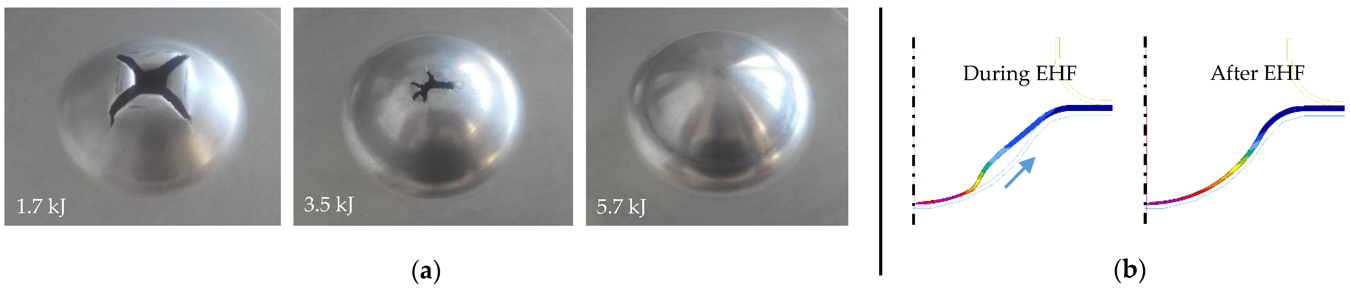
3], the compressive stresses are also transmitted downstream of the impact, i.e., in the not yet impacted zone. This compressive stress state could decrease or suppress void nucleation and growth, and therefore, prevent or at least delay the formation of damages in the following phases of deformation. Additionally, at high impact speed, a flow of material is generated downstream of the impacted zone, tending to thicken the part in the not impacted portion. This can compensate for thinning coming from bulging of the part and also prevent or postpone tearing that could happen due to excessive stretching. This ironing effect is shown in
Figure 1, where a 50 mm diameter hemisphere made from an Al 5182-O is formed by EHF at different energy levels.
Figure 1a demonstrates the increase in formability when the forming velocity is high enough, and
Figure 1b illustrates how the ironing takes place against the die, with an arrow giving the direction of the evolution of the impact.
Similar to the observations from Allwood [
8], who showed an increase in formability from 7% to 300%, Demir et al. [
4] suggest that another possible reason for the increase in formability comes from the out of plane shear stress due to the type of loading in EMF where Lorentz forces act perpendicular to the sheet. It could be the same in the EHF process.
Another possible positive effect on formability can be due to the simultaneous stretching and bending while forming. Emmens [
9] has shown an increased elongation before rupture from 25% up to 430% in a quasi-static tensile test combined with bending. Additionally, this could be similar to what has been described by Duroux [
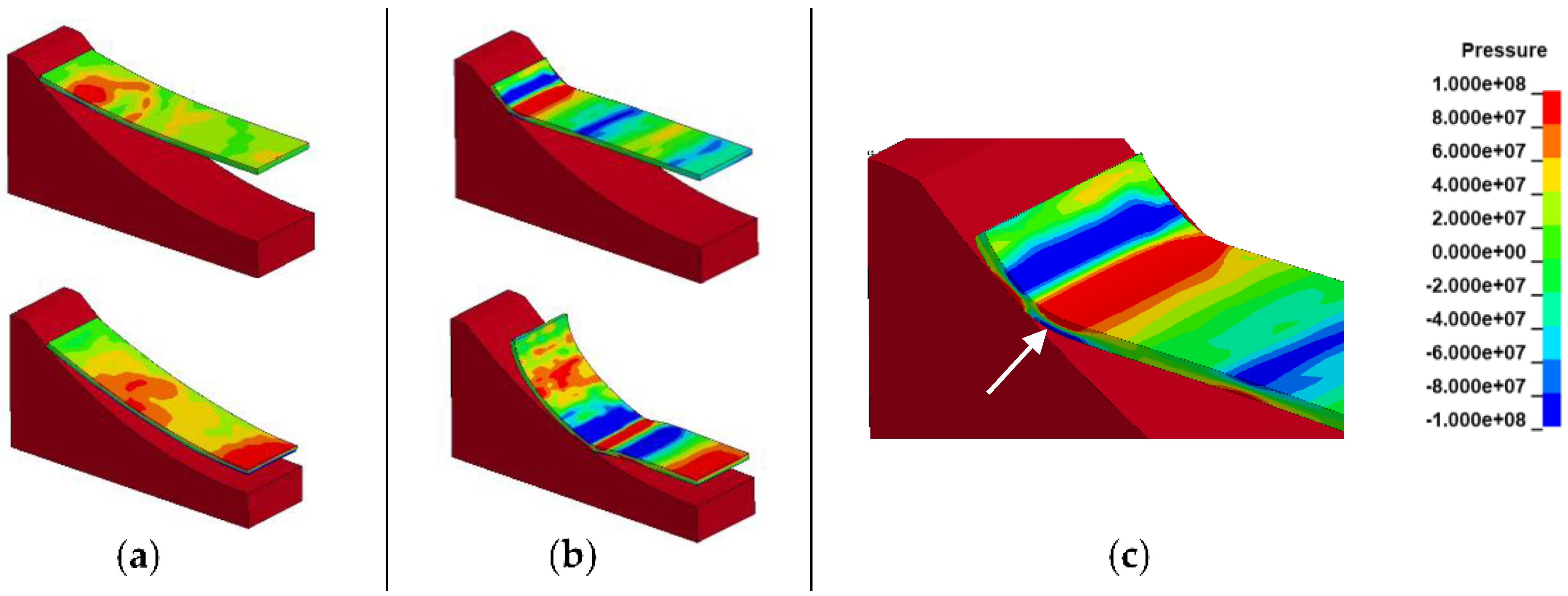
10] in conventional stamping at the entry radius of a blank drawn inside a die. These two processes generate compressive stresses in a portion of the thickness due to bending that can delay damage formation even if this compression does not occur through the whole thickness of the sheet. Similarly, in high-speed forming, if both part velocity and distance between two contact points of the part with the die are important enough, the motion of accelerated parts tends to be flat before impact. This is illustrated in simulation plots of
Figure 2 inspired from Yamada [
11] for an Aluminum strip launched with an initial vertical speed. With an initial velocity of 18 m/s (a), the shape downstream of the impact with the die is curved, while it is almost flat at 120 m/s (b). Colors represent the pressure (Pa) in the material. The detail in
Figure 2c shows with a white arrow the compression (red zone) in part of the thickness downstream of the impact point due to bending. This forming particularity should therefore contribute sometimes to the observed increase in formability due to high speed.
Based on all the above-mentioned considerations, the forming process should be designed in such a way that large strains occur to take advantage of these positive effects on formability. For example, forming local features in relatively small areas induces large strains and very high strains rates (>104 s−1). This makes it possible to perform sharp radii without tearing in particular for Aluminum, to form and engrave metallic parts with very fine details, to use stronger materials with too low formability in quasi-static forming in order to reduce the thickness of the sheet, sometimes to eliminate heat treatments by enabling to form parts directly from sheets already in their final tempered state, and more.
Regarding FLDs at high strain rates coming from experimental results published in the literature, they should be used with caution. Indeed, forming limit curves are valid for a linear deformation path, and when the full thickness is in tension, this is not always the case when forming complex shapes at high strain rates, like sometimes also with particular slow forming processes. Moreover, when an important ironing effect takes place, the thickness of a sheet reduces, and the final measured extension at the surface can sometimes no longer be due to tensile stresses alone but also through thickness compression that deforms the part in-plane due to conservation of volume. Nevertheless, analyzing deformations from simulations in FLDs before impact remains of interest to evaluate the risks of tearing.
3. Deep Drawing and High Strain Rates
Generally speaking, forming a deep cavity requires sheet metal drawing from the flange to limit deformation. High strain rates forming are generally too fast to give enough time to the material to flow extensively under the blank holder. Therefore, deep cavity parts can be formed either by multiple pulses or by preforming operations on a press, as discussed in multiple publications reviewed by Psyk et al. for EMF [
1].
The multi-pulse approach is expected to be more applicable when the cost of the tool is a more significant factor than the cycle time. The hybrid forming approach, combining possibly in the same operation quasi-static forming and pulse restriking or forming, provides a substantially shorter cycle time but requires more sophisticated tooling.
Regarding EHF, the hybrid processes can be performed by combining it either with hydroforming [
12,
13,
14,
15] or with stamping [
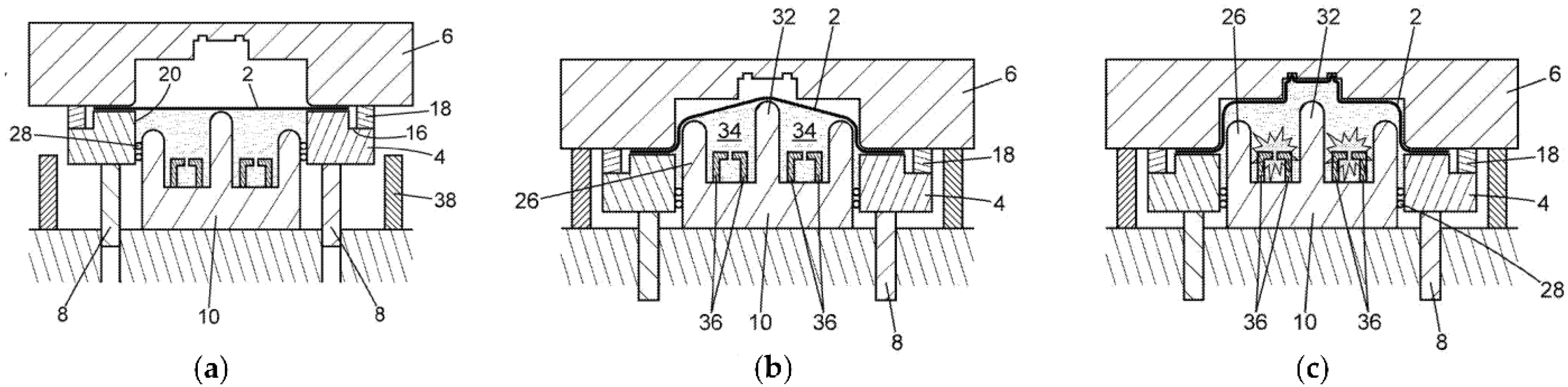
16]. To demonstrate the latter, a part was designed to be formed by a cylindrical punch in which an Electro-Hydraulic chamber is integrated to form the central shape. The principle is shown in
Figure 3.
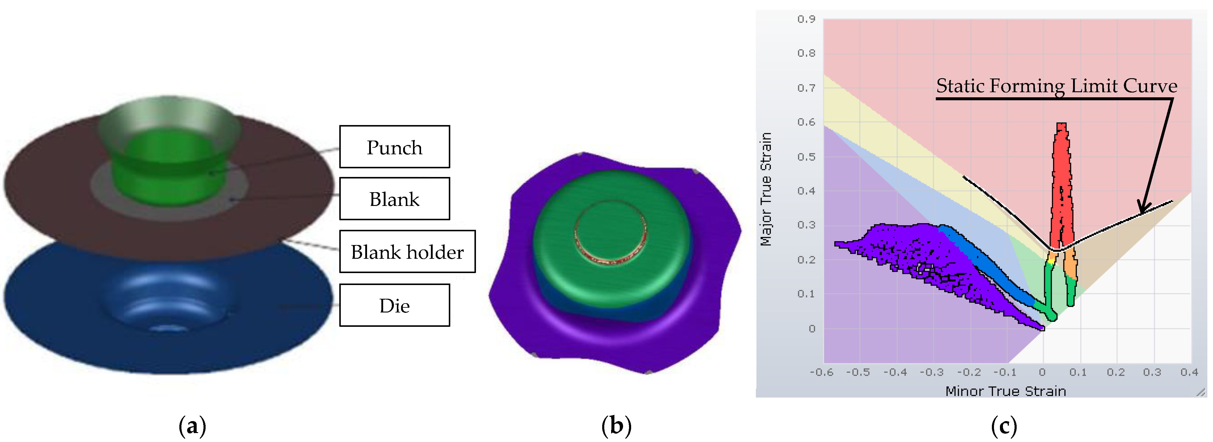
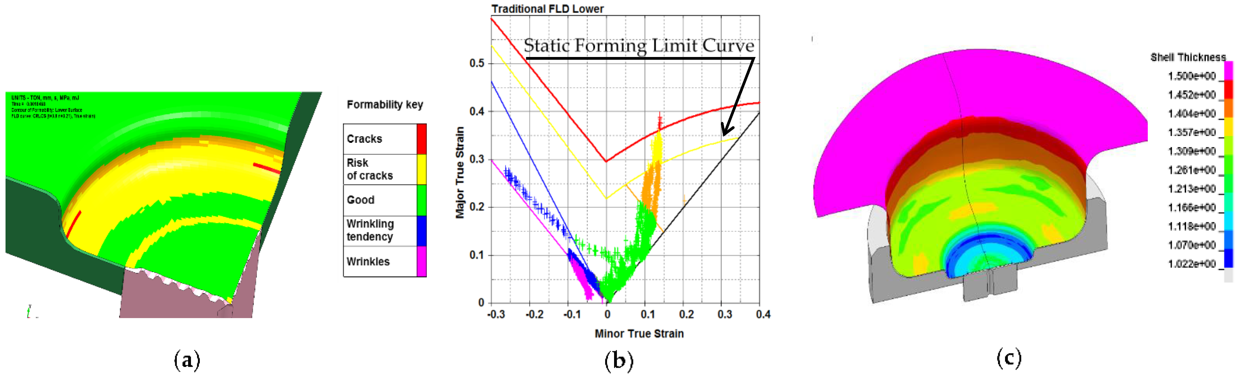
The demonstration part was made from a blank in Al 6061-T4, 1.5 mm thick. The cylindrical cavity was 200 mm in diameter and 80 mm deep. As shown on Autoform
® simulation results presented in
Figure 4, it is designed so that it cannot be formed using conventional stamping in one step. Indeed, deformations generated by the smaller central punch reported on a forming limit diagram (
Figure 4c) show red spots way above the Forming Limit Curve in plane strain.
To simulate the hybrid process combining quasi-static stamping and EHF, the LS-Dyna
® finite element software has been used. To accurately predict the forming, the evolution of the electrical power as a function of time has been taken into account with a model dependent on the parameters of the high voltage generator, as presented by Deroy [
17]. This electrical current in the arc generates pressure waves inside an Eulerian mesh, representing the volume of water, while the metallic sheet to be formed is represented by a Lagrangian mesh. At each time step, the two meshes are coupled so that the pressure generated in the water is transferred as a force to the sheet being formed. The dynamic constitutive behavior of the material depending on strain rate, as presented by Jeanson [
18,
19], is also required to correctly predict the proper strain and stresses distribution in materials. The simulation results of the combined process are shown in
Figure 5.
As seen in
Figure 5b, contrary to stamping, deformations of the central portion with EHF have positive minor deformations and so are not in plane strain. Nevertheless, some areas are still above the static forming limit curve in yellow (
Figure 5c).
The EHF generator used to produce the parts has the ability to store energy up to 25 kJ and is connected to one set of electrodes located inside the punch. It has been specially developed for mass production with a lifetime of insulators relevant for industrial applications. Typical designs of EHF electrodes are reported, for example, by Golovashchenko [
13] or by Felts [
20] without membrane and by Brejcha [
21] with membrane.
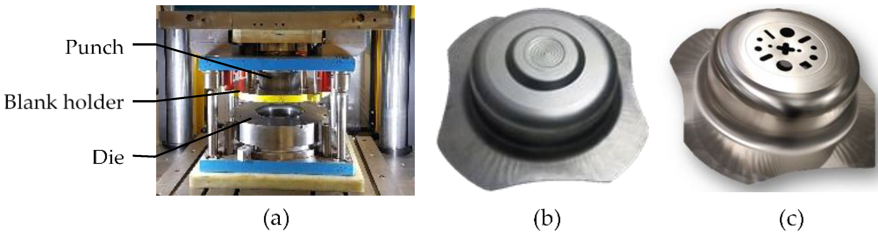
Here, the hybrid tooling is integrated into a 400-ton press, as shown in
Figure 6a. The bottom of the punch is closed by a membrane in its center to avoid contact of the formed part with water and, more importantly, to avoid time loss in water filling, allowing high production rates. For the drawing phase, a blank holder is used with the proper retaining force to avoid any wrinkle of the part when flowing inside the die.
Despite deformations above the static forming limit curve (
Figure 5b),
Figure 6b demonstrates a part formed without tearing thanks to high strain rates and the ironing effect. In addition, fine details have been formed in the center. Different shapes can be proposed by changing the central insert in the die, making it possible to perform forming as well as cutting operations (see
Figure 6c). Since no punch is used in the central area with EHF, it is easy to customize parts without time-consuming dies adjustment phases.
This application is an example presenting the interest to couple conventional deep drawing and EHF with a membrane in the same step, possibly at high production rates, in order to get shapes not feasible with mechanical stamping.
4. Hood Panel Postforming by EMF
For lightweighting purposes, integrating an EMF coil in a conventional press line gives the possibility to restrike character lines of an outer panel in order to get the radii on Aluminum as small as the ones obtained on steel panels, without tearing or visual defects.
Here is the case of the postforming of sharp edges in a Lamborghini Aluminum hood performed for design purposes as presented by Held [
22]. The requirements for the application were the forming of character lines with an edged V design 500 mm long on a hood panel made of a 1.2 mm thick Al 6016-T4, with a size of 1 m × 2 m. The idea was to produce a unique lightweight concept with sharp edges to participate in the impression of a highly dynamic car. The difficulty for a conventional stamping process was to get small radii due to the limited formability of the Aluminum at low strain rates.
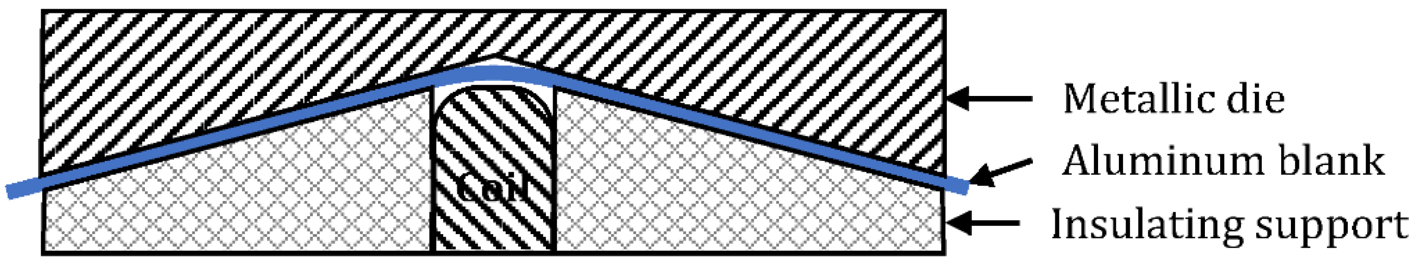
The main objectives of the project were to show the ability of the EMF process to achieve this specification without creating any surface defects, which is crucial for outer panels, to integrate the tool into a conventional production line, and to show the environmental sustainability of the process due to very low energy consumption. A cut-view of representative tooling is given in
Figure 7.
For this implementation, the process took place in a specific operation OP35 (see
Figure 8), between the trimming and the first flanging step of a press line initially comprising four operations.
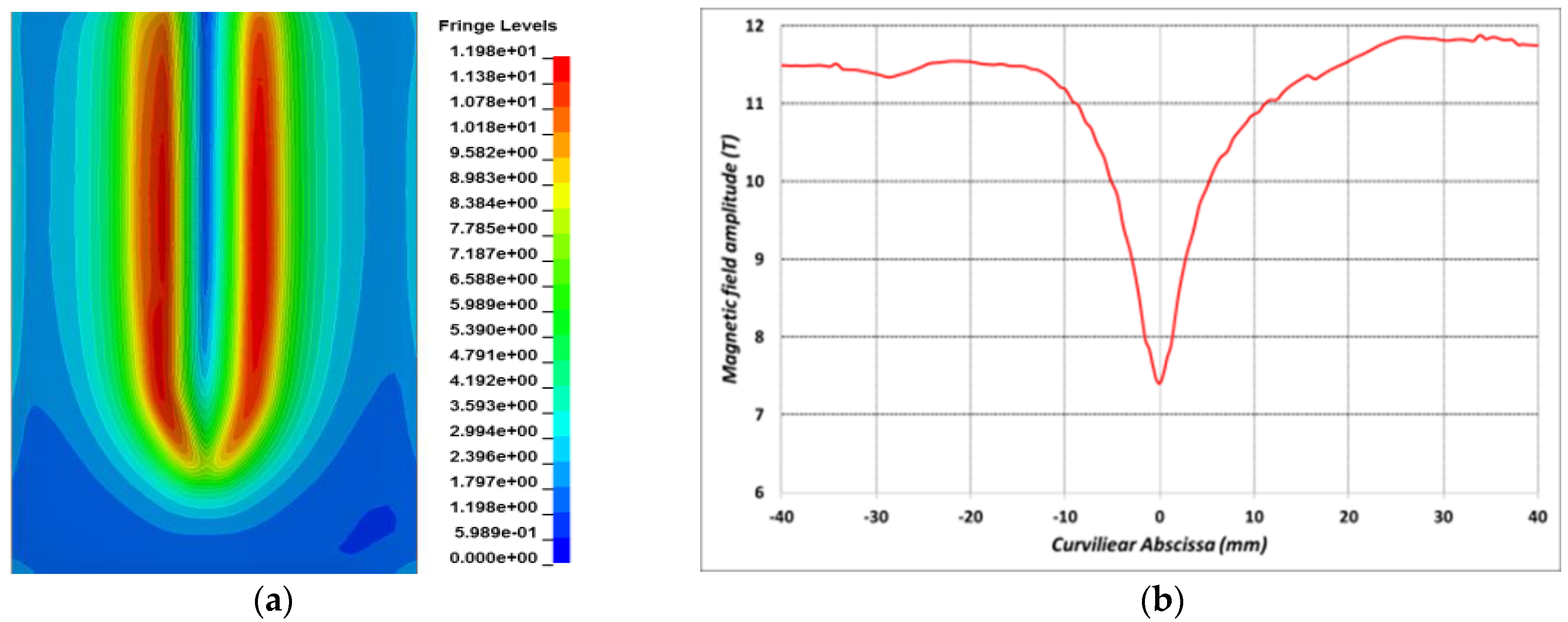
The design of the EMF tool was performed using the strongly coupled LS-Dyna simulation code, taking into account Lorentz forces, dynamic behavior at high strain rates, and heating, which remained reasonable despite the high current involved (hundreds of kA). To generate appropriate Lorentz forces in order to get a uniform final radius along the character line while respecting acceptable stresses in the whole one-turn coil, 2D and 3D simulations were performed with specific attention to the slot region of the coil where the current enters and leaves the coil. To get the forming there, the magnetic field was kept above a certain value (see
Figure 9). The required energy to get the final part was 15 kJ delivered in one discharge.
The process robustness and reproducibility are mainly ensured by the precision of the charging voltage, the part positioning, a peak current high enough to form whatever the material batches, and the coil insulation material. An important phase to avoid any surface defects on the part is the spotting operations to adjust the surfaces of the non-conductive support around the coil. Such operation in conventional stamping is much more time-consuming, as both metallic die and punch surfaces need to be adjusted with extreme precision by manual grinding, honing, and polishing.
Figure 10b,c shows the ability of the tool to create very sharp features. In these pictures, a sharper than needed radius was produced, with a final measured radius of 0.1 mm, starting from 4 mm.
At the end of the process, the material flow seems closer to forging than forming and shows how high strain rates make it possible to form sharp corners with high local deformation without rupture. However, radii of about 1 mm are more generally used by car manufacturers for optimum painting and pedestrian safety issues.
This on-site, small series production made it possible to qualify the technology in terms of integration in a press line and safety. Since then, in other projects involving Renault [
23], such EMF tools were integrated directly in the last flanging step and used for larger series production. A cooling system was integrated into the tool to ensure that the production rate of the press line could be maintained, and a specific automated connection system was developed to respect the tooling changing time requirement of press lines. Typical times to change all the tools, such as those in
Figure 8, in order to start a new series production, are between 4 and 20 min depending on the car factory. The EMF process and produced parts were fully qualified, including production rate, coil lifetime, surface quality, painting quality, as well as parts microstructure and mechanical strength.
5. Embossing by EHF for Luxury Packaging
To show the ability of EHF to create embossing, the example of the “J’Adore L’Or” perfume bottle cap is taken. This design received the Packaging of Perfume Cosmetics and Design award at the PCD Paris 2018 event.
To manufacture perfume caps in metal for premium products rather than metalized plastics, leading brands generally use Zamak casting. An alternative to this zinc-based alloy is the use of Aluminum processed by EHF.
The blanks are made of Aluminum alloy 5657 with a thickness of 0.8 mm. As for the EHF application shown previously, the process was modeled by a fluid-structure interaction and a time-dependent energy deposition to generate the correct pressure waves resulting from the discharge, and therefore, to properly predict the forming. This is illustrated in the example in
Figure 11, where a parallel between simulation and experiment during the forming sequence of the cap is presented. Pressure contour plots are shown at four different timesteps, revealing the dynamic forming of the blank that impacts the die with peak velocities above 100 m/s.
In static, the uniaxial strain to failure of the Al5657 was 17%. Extrapolating this data and building the theoretical forming limit curve in biaxial expansion by the Storen-Rice formula, one finds 20% in major strain and 20% in minor strain. In the case of the cap, the deformation in the top corner reaches 40% in major strain and 20% in minor strain without rupture. Ironing and bending while forming phenomena that explain part of this increase in formability can be seen at the impact location with the die in the simulation plot of
Figure 11 at time t = 50 µs (red circle). Regarding the details, they are properly formed once the shape of the bottom corner is complete and thanks to a reflected wave with increased pressure moving up, coming from the bottom of the part (see simulation plot at t = 119 µs).
Other relevant features of the “J’adore L’Or” perfume caps are the sharp angles and very fine details achieved shown in
Figure 12b,c. The different manufacturing steps are also shown in
Figure 12a. The cap is made by assembling two parts, with one remaining on the glass bottle. The blanks are formed with a conventional progressive stamping process by the G. Pivaudran company, as well as the final cutting, anodization, and assembly. The whole EHF step was developed and is performed by Bmax.
For the first time using the EHF process, mass production has been performed with a fully automated production line. Parts production of this new design had been performed over seven months for the launch of the product and continued for the following years.
Figure 13 shows a single soundproof integrated EHF machine located around a pooled conveying system able to produce such a part. Its production capability in three shifts is 1 million parts per year, using only one electrode system.
Several EHF machines like the one in
Figure 13 can be placed around this conveying system in order to increase the production rate or to produce different parts as the conveyor is equipped with a handling robot capable of optically detecting the type of parts that are being fed.
Thus, the increase in formability of this Al 5657 due to high strain rates gave the possibility to use Aluminum instead of Zamak casting, offering finer engravings, a larger color palette thanks to anodization, a durable product, and a substantially greener process. This is another example of how ultra-high-speed forming can push the current design limitations.
6. Radio-Frequency Half-Cavities Formed by EHF
EHF has been explored for the production of several Superconducting Radio Frequency half cavities for CERN of 400 MHz, 800 MHz, and 1300 MHz. The main results have been described by Atieh [
24] and Cantergiani [
25,
26]. The 400 MHz frequency cavities made of electronic oxygen-free electronic (OFE) copper are used for the large hadron collider (LHC) and will also be used a priori for the future circular collider (FCC) that was initially foreseen at 700–800 MHz using high purity bulk niobium. Traditionally, such cavities are fabricated by the electron-beam welding of half-cells obtained through sheet metal forming techniques such as deep-drawing, spinning [
24], or hydroforming [
27]. These traditional shaping methods show several drawbacks. The first two of them leave 100–200 µm of the inner surface damaged layer due to friction with the tools, and this layer needs to be removed by buffered chemical polishing to improve RF performances. For deep drawing producing complex shapes with high accuracy, it is difficult, and for large half-cells, such as the 400 MHz ones, it would require high-tonnage hydraulic presses. Furthermore, springback causes significant deviations from the die geometry, in particular in the central area—the iris—[
28] despite die compensation. Thus, for large components, a combination of spinning and machining to get the proper geometry was initially preferred. However, this also presents some disadvantages as it requires several spinning steps, including intermediate annealing, to avoid necking [
29]. Full cavities without weld at the equator can also be obtained through hydroforming from a tube [
27]. The springback is also an issue for this process, and the precision of the internal RF surface is highly dependent on the thickness variation due to the stretching and tolerance of the starting tube. Thus, geometrical tolerances remain large here also. Moreover, if Niobium is used, tube procurement is an issue financially and from a supply point of view.
These drawbacks associated with traditional techniques can be overcome or limited by EHF, making it possible to get tight geometrical tolerances due to the reduced springback and to avoid intermediate annealing due to the increase in formability.
For such large parts, multiple shots are required to get the final geometry. OFE copper and Niobium constitutive laws have been shown to be very sensitive to strain rates for a few 10
3 s
−1 [
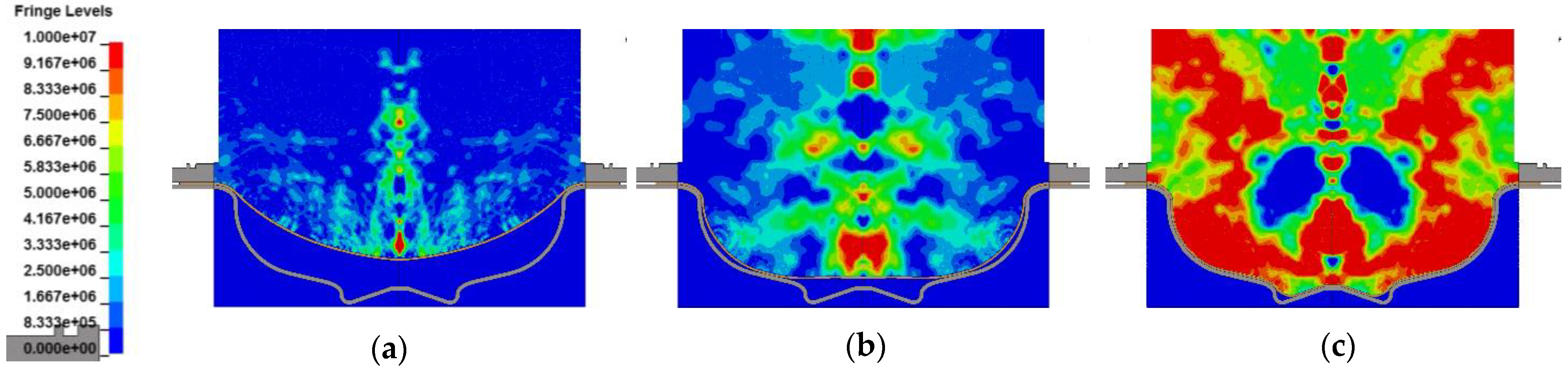
26]. Thus, proper material models are mandatory as input in simulations to optimize the EHF process parameters, such as the energy level, the number of electrode systems, and the number of successive discharges. At the end of the simulation for a shot, the deformed sheet with its residual stress-strain distribution is used as a starting blank to simulate the next forming shot. An example of 3 simulated forming shots for a 700 MHz half-cell is shown in
Figure 14, where the evolution of deformation can be seen. As the initial diameter of the blank is the same as the external diameter of the blank holder, one can see that shot after shot, the material is drawn inside the die.
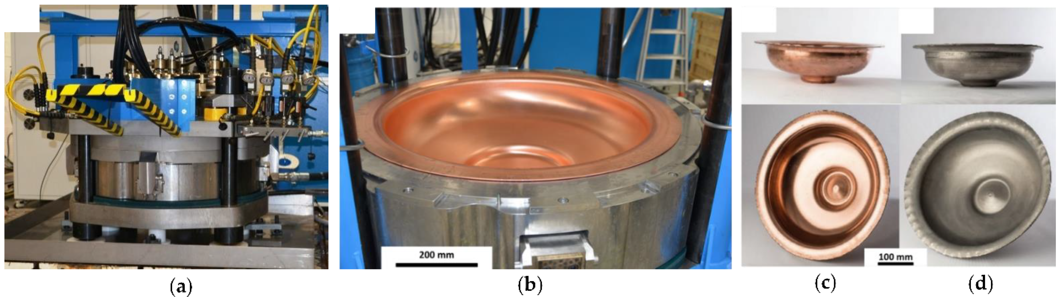
Figure 15a shows the EHF set-up used to produce the 400 MHz half cells of
Figure 15b, and examples of 700 MHz half-cells are given made of OFE copper in
Figure 15c and niobium in
Figure 15d.
The shape accuracy of 400 MHz half-cells formed by EHF was compared at CERN with the shape accuracy of 400 MHz half cells obtained by spinning, including an intermediate annealing step and complete machining of the inner surface [
30]. The latter were obtained starting from a blank of 4 mm in order to have enough material for the final machining step to achieve the required inner shape.
EHF was performed on copper sheets of 3 mm thickness without any intermediate annealing or machining. The results obtained by geometry control are shown in
Table 1, and the roughness values are shown in
Table 2.
From the values, one notices that EHF gives results in agreement with the precision required and is more precise than spinning and machining. Moreover, as shown in
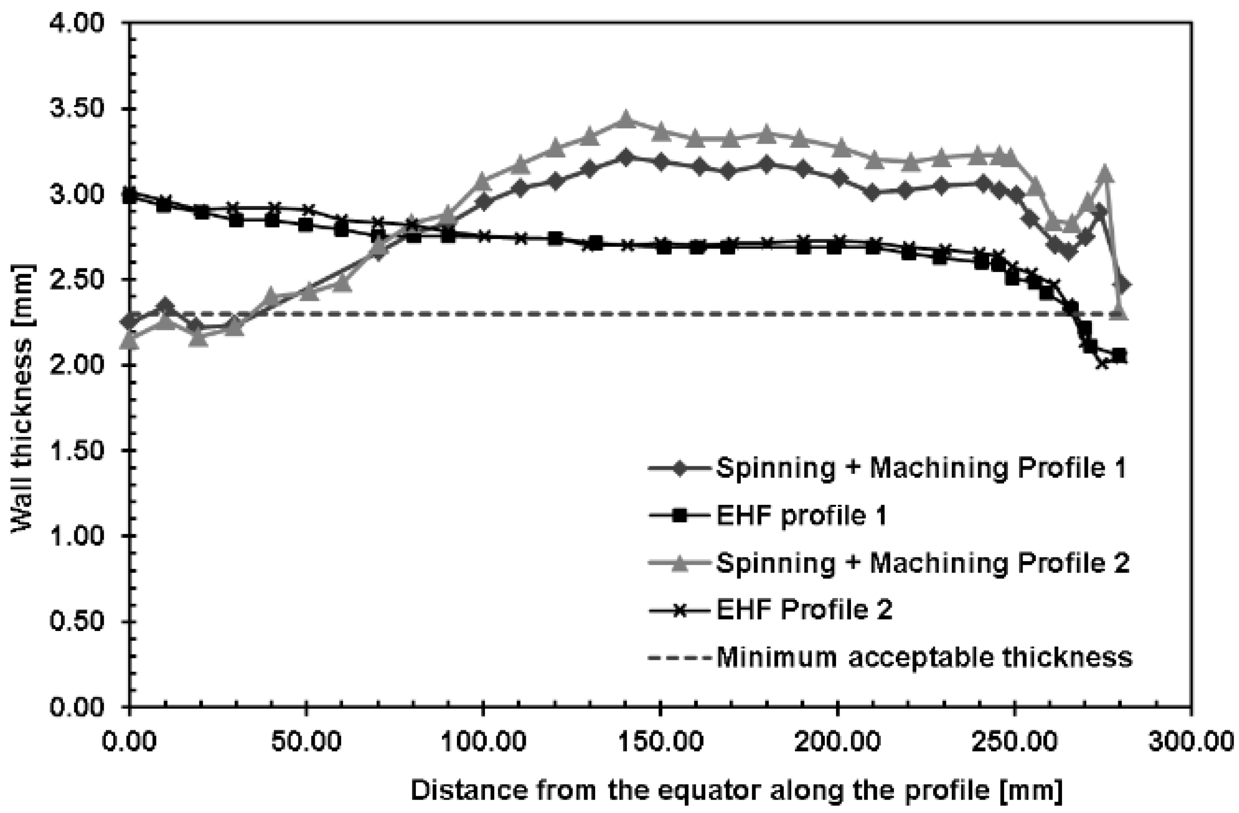
Table 2, the value of roughness before and after EHF is preserved both for copper and niobium half-cells. The thicknesses of the formed 400 MHz half-cell were extracted for both EHF and spinning and are shown in
Figure 16.
As shown in
Figure 16, the thickness distribution found for EHF is homogeneous on the whole half-cavity profile with values between 3 mm and 2.3 mm as required by CERN. Only the thickness at the iris was slightly lower than 2.3 mm, but this was accepted by CERN after structural verification of the loads encountered by the SRF cavity during the operation. The thickness distribution obtained from spinning and successive machining shows a higher variability. Moreover, at the equator, the thickness is slightly below 2.3 mm, and in most of the profiles, the thickness is higher than 3 mm, which can result in difficulties when the half-cell needs shape deformation to obtain proper RF response (tuning of the cavity [
30]).
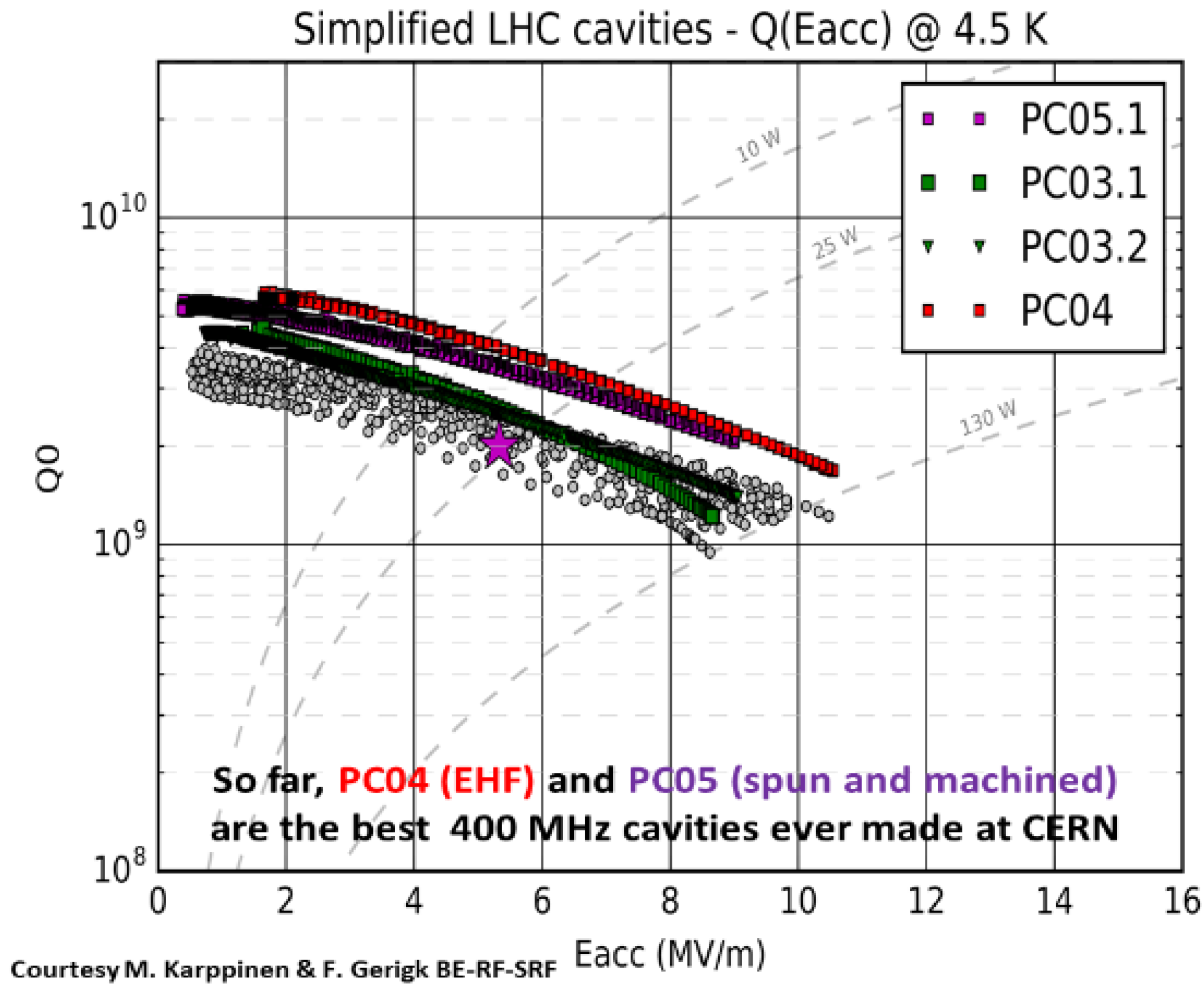
Finally, EHF is the process chosen by CERN to supply spare parts for the LHC. In addition to the manufacturing benefits, the RF results obtained on a 400 MHz full cavity formed by EHF were best, as shown in
Figure 17 disclosed by CERN [
31]. This graph showing the quality factor (Q
0) versus the accelerating electric field (E
acc) is typically used to measure RF performance, relating the conductance of the inner surface of a given cavity geometry to the maximal electric field before quench where the cavity loses its superconducting quality (here, above 10 MV/m for the EHF cavity).
Therefore, from an industrial point of view, EHF is very attractive to reduce fabrication time, decrease the cost of half-cells of RF cavities and improve their performance due to higher precision and better inner surface quality.
7. Oil Deflector for Helicopters
A study was led concerning the forming of an oil deflector using the EHF process, and D. Allehaux presented the results [
32]. This work is the result of a close collaboration between the industrial end-user (Airbus Helicopters) and the technology supplier (Bmax). The objective was to verify the ability of the EHF process to form the part starting from a plate having the final expected temper state. The motivation was to perform global manufacturing lead time optimization and cost reduction compared to the applied conventional manufacturing method, but also to check the EHF process robustness and to use a greener technology.
The blank is made of Al 6061 blank, 1 mm thick, and the part has a final diameter of approximately 400 mm.
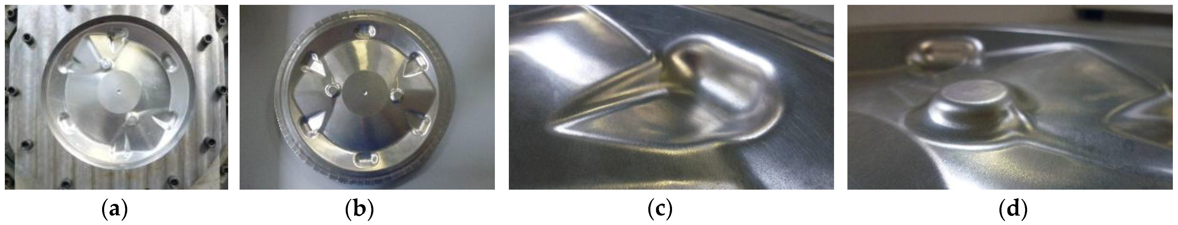
The traditional method to manufacture this part is to start with a blank in a T0 state so annealed. It employs two dies (one male and one female), three stamping steps on a rubber press that includes a final restriking operation on the female die, two intermediate aging thermal treatments, a full thermal treatment made of solution heat treatment, quench, and natural aging and a final manual rework after the restriking operation. The EHF die and the part with details are shown in
Figure 18. The die has been machined directly from the theoretical geometry of the part. Details show how EHF makes it possible to form undercuts and complex shapes without time-consuming die adjustment.
The part formed by EHF was initially a flat blank in the T4 state, so hardened by heat treatment, which is the final expected temper for the part in the operation. The geometry was fully formed in three shots, using a three electrodes system due to the size of the part.
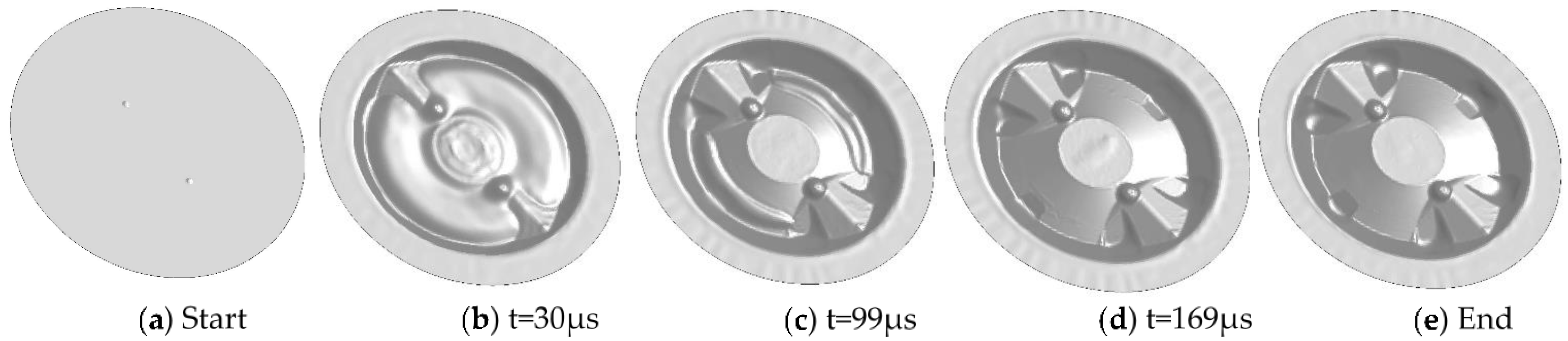
Simulations were performed to define the process parameters of the three different shots.
Figure 19a–e presents one of the simulations of the first shot showing the progressive forming process and how dynamic it is. Instead of the bulging that would occur in conventional hydroforming, the part is pushed onto the die by radial ironings from the center to the periphery and from the periphery to the center. Both then make some extra material appear in the (c) picture, flattened later without wrinkles in the (d) picture, and helping to form the grooves without tearing. The two additional shots not shown here finalize the forming of the grooves.
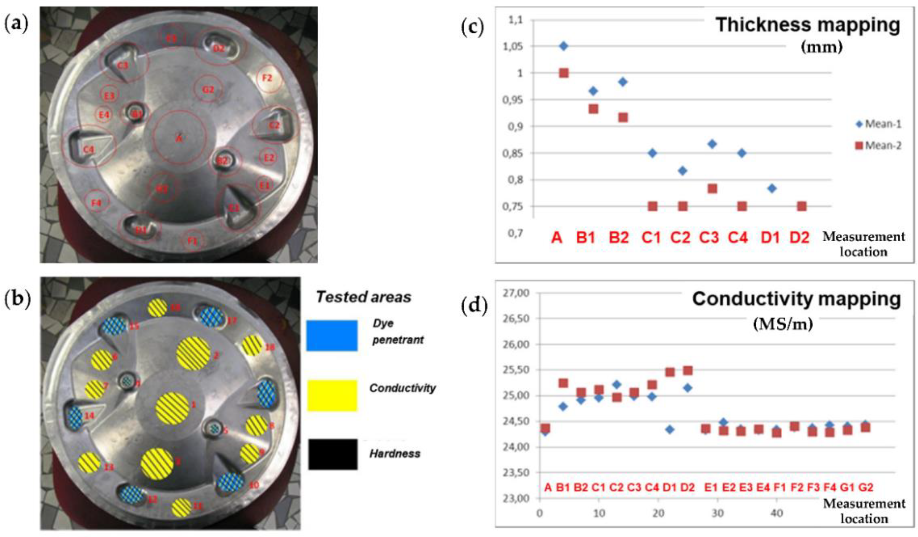
Several analyses have been performed on the part after EH forming by Airbus Helicopters, such as geometrical measurement including thickness, crack detection using dye penetrant analysis, local conductivity, and hardness. No tearing occurs, although a maximum of 35% thinning was observed in the grooves located on the periphery (see C and D points in
Figure 20c). With the conventional slow forming method, only 15% maximum thinning was possible before tearing at these locations. As expected, local hardenings have been observed in the highly deformed areas (zones B, C, and D in
Figure 20a), and the conductivity measured was close to the T6 temper in the D areas (see D1 and D2 points in
Figure 20a), so harder than T4.
The process has been shown to be reproducible from one plate to another. Getting the part without tearing was possible only by controlling the drawing of the part below the blank holder to avoid excessive deformation and the location and the energy level of the discharges. The drawing of the material under the blank holder was obtained by successive EHF discharges without combining them with hydrostatic pressure or stamping. As for the forming examples presented before, high strain rates combined with ironing and bending have been observed in simulations and explain the gain in formability that was noticed.
With these results, cost reduction by Airbus on the product was estimated to be up to 60%, including recurring and non-recurring costs.
8. Some Limitations When Forming by High Strain Rates
Psyk et al. [
1] gave a global overview of limitations concerning the EMF process. Even if some issues of this technology have been solved since then, it is interesting to refer to this article for a deeper view.
Among the main limitations of EMF and EHF, even if higher strain rates can bring potentially better formability, the impact speed often has to be limited to avoid too high stresses on the die and surface defects on the formed part due to bounce-back or jetting effects. For the latter, similar to impact welding processes, jetting can appear at high velocity between the part and the die due to hydrodynamic phenomena when the angle between the two parts is favorable (typically between 5° and 15°), tending to remove micrometers of materials from the surfaces of both the part and the die.
A limitation also comes from the thickness of the parts to be formed. Indeed, energy requirements increase directly with the thickness, which tends to increase the cost of the generators and decrease the lifetime of the tools (coils in EMF processes, electrodes, and insulators in EHF processes) as higher pressures are required to deform thicker parts.
For high strain rate forming processes, the lifetime of these tools is generally lower than the one of metallic punches in traditional stamping processes. This is often related to areas where significant dynamic forces and/or temperatures are applied. Therefore, the mechanical strength and lifetimes of high voltage insulators, as well as conductors driving high energy densities, are a point of attention for high volume pulsed forming applications. Their lifetime depends on the design, energy, peak pressure, current density, or electric fields involved. Therefore, to optimize the design of these components and to choose the proper materials, strongly coupled simulations are of interest. Currently, high-volume industrial solutions are running using either long-life or cheap and easy-to-replace materials in critical areas. Their lifetime can be in a range from several thousand to more than a hundred thousand pulses.
9. Conclusions
Firstly, a synthesis was proposed giving an overview to explain why high strain rates can increase the formability of metals, as this ability is one of the important competitive advantages compared to quasi-static processes. The phenomenon of bending downstream the impact on the die has been proposed as one of the possible reasons for this increase in formability.
Several recent industrial applications of EMF and EHF processes were then described for high and low volume production. A particular focus was made on simulation results in order to deal with the formability of these parts and to better visualize the type of deformations specific to high-speed forming. An application in deep forming has been presented, combining stamping and EHF to take the advantages of both processes. An example of postforming by MPF showed how to create sharp radii in the automotive industry, possibly for high-volume applications. A high-volume embossing application using EHF in luxury packaging demonstrated how highly dynamic forming can make it possible to form complex shapes rather than cast them. Two other examples for the aeronautic and particle accelerator industries disclosed how the improvement in forming limits can reduce manufacturing costs, in particular by avoiding annealing and/or machining steps.
Nonetheless, to help have a more global picture from an engineering point of view, some limitations of the EMF and EHF processes have been pointed out.
As a whole, the presented applications brought specific insight into the possibilities to use these high strain rates processes for different purposes, including lightweight designs, manufacturing cost reductions, new shapes, improved perceived quality, and higher precision.


