
Influence of the Production Process on the Binding Mechanism of Clinched Aluminum Steel Mixed Compounds

Institute of Manufacturing Science and Engineering, Technische Universität Dresden, Helmholtzstraße 10, 01069 Dresden, Germany
*
Author to whom correspondence should be addressed.
J. Manuf. Mater. Process. 2021, 5(4), 105; https://0-doi-org.brum.beds.ac.uk/10.3390/jmmp5040105
Submission received: 16 July 2021
/
Revised: 10 September 2021
/
Accepted: 27 September 2021
/
Published: 30 September 2021
(This article belongs to the Special Issue Metal Forming and Joining)
Abstract
:The multi-material design and the adaptability of a modern process chain require joining connections with specifically adjustable mechanical, thermal, chemical, or electrical properties. Previous considerations primarily focused on the mechanical properties. The multitude of possible combinations of requirements, materials, and component- and joining-geometry makes an empirical determination of these joining properties for the clinching process impossible. Based on the established and empirical procedure, there is currently no model that takes into account all questions of joinability—i.e., the materials (suitability for joining), design (security of joining), and production (joining possibility)—that allows a calculation of the properties that can be achieved. It is therefore necessary to describe the physical properties of the joint as a function of the three binding mechanisms—form closure, force closure, and material closure—in relation to the application. This approach illustrates the relationships along the causal chain “joint requirement-binding mechanism-joining parameters” and improves the adaptability of the mechanical joining technology. Geometrical properties of clinch connections of the combination of aluminum and steel are compared in a metallographic cross-section. The mechanical stress state of the rotationally symmetrical clinch points is qualified with a torsion test and by measuring the electrical resistance in the base material, in the clinch joint, and during the production cycle (after clinching, before precipitation hardening and after precipitation hardening).
1. Introduction
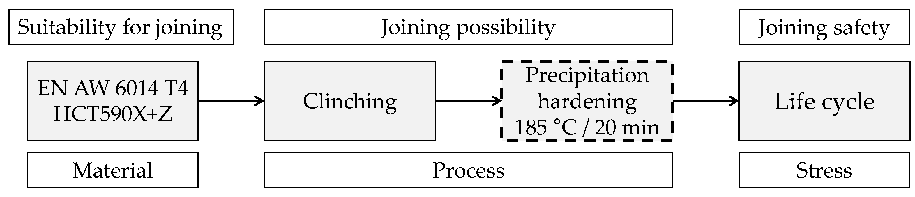
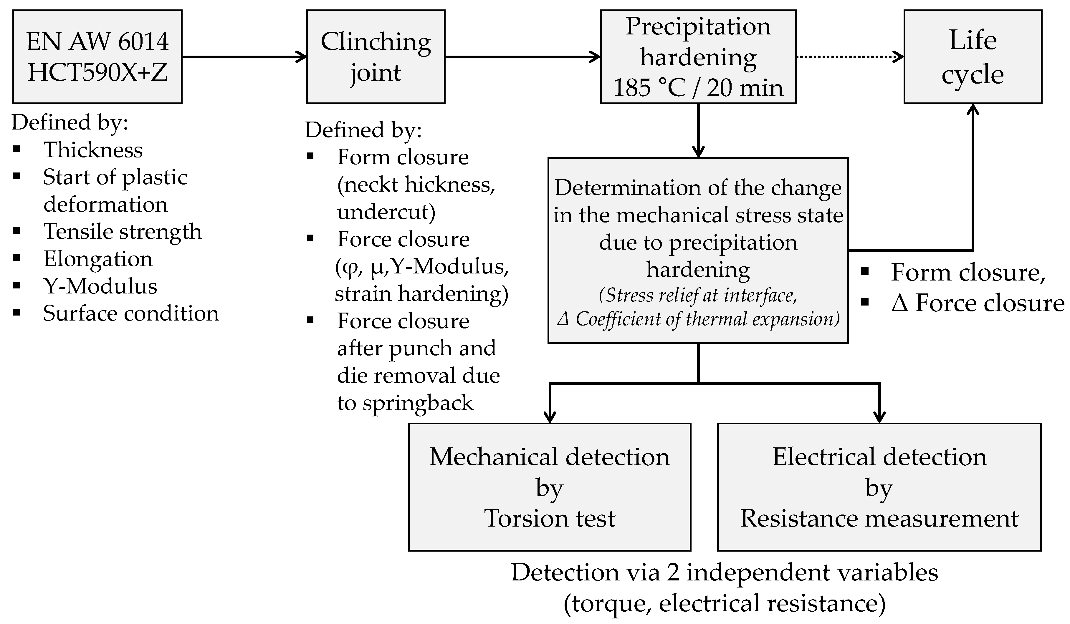
The technical task of joining materials leads against the background of steadily increasing functional integration in production to expanded or new requirements for joining technology. Joining connections of the most diverse materials are becoming increasingly important. In order to enable a function- and cost-related mixed design on a larger scale, further developments in joining technology and a material overview for these mixed constructions are necessary. This means increased planning effort in design and logistics, but offers the possibility of using the materials more according to needs. Furthermore, with today’s safety requirements and standards, continuous monitoring and documentation of the entire manufacturing process must be ensured. Forming technologies are an established joining process for overlapping sheet metal [1] and profile parts and have a wide range of applications [2]. For example, clinching can be used to join semi-finished products of equal or different thicknesses as a joint of identical materials [3] or with different tool geometries [4]. Eshtayeh describes in [5] the clinching process of dissimilar joining partners in general. Especially the joining of aluminum and mild steel [6], the advanced high-strength steel DP780 and Al5052 alloy [7], or the Al5052 alloy with steel grades up to 1000 MPa tensile strength in [8] also with adaption of the die tools [9] and hot dip coated surfaces [10] are state of the art. Furthermore, copper materials or mixed compounds of aluminum and copper for electrical applications can also be clinched [11]. For the clinching process, it is necessary to meet the requirements for clinching. Components meet these requirements when, by local forming of a material, a form- and force-closure can be produced in the first instance and a material-closure in the second. The properties of the joint, as well as the connected structures, must satisfy the requirements specified for them. As in [12], the clinching ability results from the influencing variables material, design and process as shown in Figure 1.
An advantage of clinching is that the joined components can be further processed immediately after the joining process due to the binding mechanisms of a clinched joint. Clinched joints function on the principles of form and force-closure comments Groche in [2]. In addition, material closure may also be present—as described in [13]—or it can be introduced in a targeted manner [14].
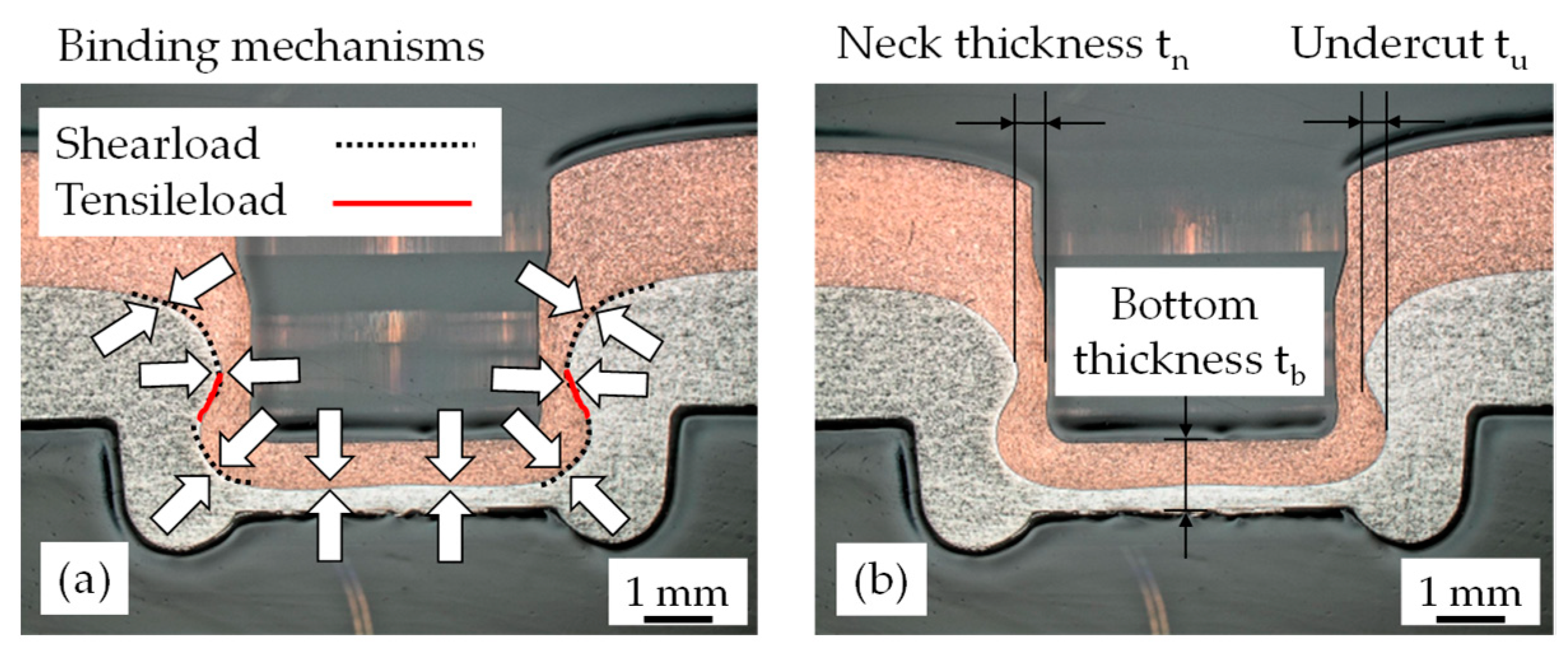
The amount of form-closure generated within the clinch point depends on the direction of loading. If the clinch point is subjected to a shear tensile load or a head tensile load, the form-closure components correspond to the areas shown in Figure 2a. The force-closure component and a possible material-closure component are independent of the loading direction. The force-closure component acts along the boundary line between the formed parts, which is marked with arrows (Figure 2a). The design of clinched joints is primarily based on the geometric characteristics of neck thickness tb and undercut tu (Figure 2b) as well as the main load case in the later life cycle. According to the state of the art, the force-closure component has not yet been taken into account for the design. Salamati summarized in [15] that, at clinched joints, the form-closure component is utilized but the force closure component is only partially utilized. Therefore, if it is possible to quantify these components, an improvement of the joint properties can be achieved depending on the type of loading. When joining different materials, the mechanical stress states [16], and thus the proportions of the binding mechanisms, form-closure and force-closure differ considerably according to the joining part arrangement due to the inhomogeneous shape changes introduced by the clinching process.
When using age-hardenable aluminum alloys, precipitation hardening of the aluminum material takes place after the joining process and before the subsequent life cycle (Figure 1). The necessaryprocess heat introduced during this step increases the strength of the aluminum alloy. Due to the large local deformations of the joining parts during the clinching process [11], the recrystallization temperature is reduced [17]. This results in a reduction of force in the joint, which causes a change in the surface pressure between the parts to be joined and thus influences the existing binding mechanism of the force-closure component.
The goal of this paper is a description of these existing form- and force-closure components during the production process. With regard to the joinability, the factors influencing the formation of the form- and force-closure components can be defined. By knowing these influencing factors, it is possible to produce a functional and function-related clinch connection.
2. Materials and Methods
2.1. Materials
Based on the joining task of producing a steel-aluminum mixed joint in both joining directions using age-hardenable aluminum alloy and a dual-phase steel by clinching, the effect of the manufacturing process on the individual proportions of the binding mechanisms is to be determined. In the investigations carried out, the aluminum material EN AW 6014 in the T4 heat treatment condition (solution annealing) with a component thickness of t = 2.0 mm and the dual-phase steel HCT590X+Z (hot-dip galvanized) with a component thickness of t = 1.5 mm and a zinc coating of thickness tZn = 7.82 µm (SD = 1.20) were used. The aluminum was delivered by Novelis Global Automotive and the steel was delivered by Salzgitter Flachstahl GmbH. After delivery, the aluminum materials were stored in a climate chamber at −22 °C until further processing in order to maintain the T4 condition. Table 1 shows the chemical formulation of the materials.
2.2. Design of Joints
The clinch points were initially designed according to [20] with a single-stage round joint with closed die and without cutting elements by using a nominal diameter of the die of 8 mm. To join the materials a displacement-controlled clinching process was used. The tool geometries of the punch and die, the blank holder or stripping force and the punch penetration depth define the form closure of the clinch connection. The joining partners, the friction between the joining partners, the local degree of forming, and the springback effect of the joining part materials define the force-closure component within the clinched joint.
Two different surface conditions of the components were investigated. In the “Cleaned” (O1) condition, it provides a defined surface condition by cleaning with isopropanol. Contaminants on the surface—such as oils, greases, dusts, and inhomogeneities—are thus removed. The treatment did not affect the oxide layer on the aluminum components in terms of their structure and roughness, as characterized in [21]. These surface condition correspondents with the definition of Kogut in [22]. The “delivery condition” (O2) represents a non-defined surface condition, which exists due to the manufacturing process, the semi-finished product transport and the handling during specimen production at the joining process. At this condition can exist a contaminated surface, described in [23], between the joining partner, which influences the friction and the electrical contact behavior.
These two surface states characterize a change in the tribological system and can initially affect the geometric formation of the undercut and neck thickness quality criteria. Table 2 shows micrographic cross-sections of the resulting clinch joint as well as the influence of the two conditions on the quality criteria. In addition to geometric changes, a change in friction also leads to a change in the mechanical stress state between the joining partners, which cannot be detected in terms of dimensions, and thus to a changed force-closure component.
2.3. Mechanical Test
After clinching, the joined components are subjected to a heat treatment. This precipitation hardening takes place according to the manufacturer’s specifications [18] for 20 min at 185 °C. Table 3 shows the changing mechanical material properties.
The introduced process heat for this precipitation hardening and the different thermal expansion coefficients of the joining partners initially influence the proportion of the binding mechanism force-closure within the clinch point due to a change in the mechanical stress state. The change of the mechanical stress state depends on the component arrangement and the surface conditions. The form closure, on the other hand, is not affected.
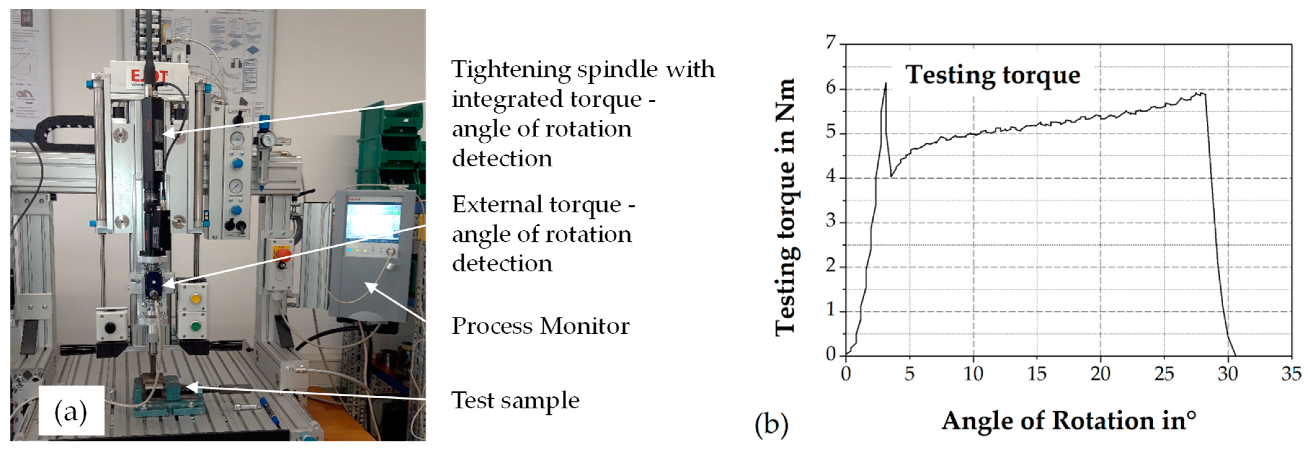
This changed force-closure component can be mechanically verified for rotationally symmetrical clinch points by means of a torsion test. The test rig consists of a tightening spindle with integrated torque-angle detection (Figure 3a). The test result is the testing torque, which is measured during the torsion of the two joining partners against each other. A large testing torque indicates a large force-closure component.
Figure 3b shows the plotted characteristic test curve. The first local maximum after the monotonic increase of the graph represents the testing torque. When this peak is reached, the two joining partners start to twist against each other. The subsequent increase in torque is due to the leveling of the roughness peaks and the associated change in the coefficient of friction between the components in the interface as a result of further rotation.
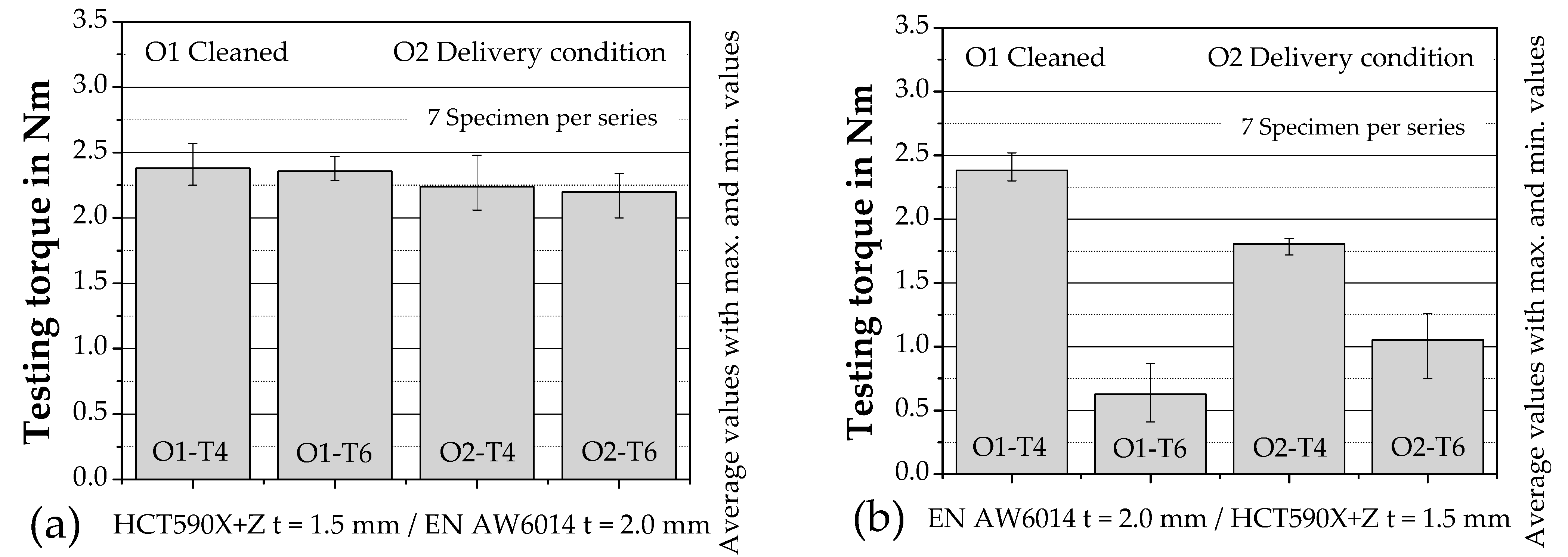
The diagram (Figure 4a) shows the testing torques for the component arrangement of the aluminum as the die-side joining partner. Here it can be seen that initially the surface condition exerts nearly no influence on the torsional torque. On average, the samples cleaned with isopropanol exhibit a 6.3% higher torsional torque in the T4 condition and an 8% higher torsional torque in the T6 condition, but the average values are covered by the scatter bands. These minor increased values for the cleaned surface condition, compared to the as-delivered condition, exists due to the increased friction between the joining partners during the relative movement at the clinching process. The increased friction leads to an increased force-closure component in the joined joint. If, in addition to the surface condition, the values achieved for the breakaway torque after precipitation hardening are also compared (Figure 4a), no significant difference in the mean values can be detected here, and the maximum and minimum values are in almost the same ranges. This is due to the component arrangement, the different springback behavior, and the introduced shape change. In this combination, the more thermally sensitive aluminum material is located on the die side—i.e., the different coefficients of thermal expansion of the component materials initially reduce the surface pressure between the components during heat treatment. After completion of the heat treatment and elimination of the thermal load, the surface pressure increases further due to the different thermal expansion of the joining partners. The second influencing factor is the springback behavior. Resulting from the greater springback of the aluminum material, a larger force-closure component is achieved irrespective of the surface condition. The third influencing factor is based on the lower deformation of the die-side component and thus on a low thermal sensitivity regarding recrystallization because of precipitation hardening.
If the aluminum material is arranged on the punch side, significant differences can be detected in the torsional test regarding to both the influence of the surface condition and the precipitation hardening process (Figure 4b). With respect to the surface condition, cleaning with isopropanol in the heat treatment condition T4 results in an increase of the torsional torque by 17.5%. This increase can be attributed to the increased friction coefficient caused by the cleaning. A comparison of the same surface, but different heat treatment conditions, show a significant reduction in torsional torque. For the series with cleaned surface, this torque loss amounts to 71%. The torsional torques of the as-delivered series differ by 39%. This indicates a reduction in the force-closure component associated with the lower torsional torque. When the more thermally sensitive aluminum material is arranged on the punch side, the maximum deformation occurring in the neck area leads to a reduced the recrystallization temperature [15]. During precipitation hardening, the expansion of aluminum is restrained by the die side steel due to the lower thermal expansion coefficient of steel. Both effects lead to a further change in the mechanical stress state by reducing the surface pressure at the clinch point. The influence of the different springback behavior of the component materials is independent of the heat treatment performed. Due to the greater springback of the aluminum cup compared with the steel on the die side, there is a reduced surface pressure between the joining partners.
2.4. Electrical Test
The values measured in the torsion test are to be verified using a second independent physical quantity. A clinch point represents not only a mechanical but also a stationary electrical contact system [14]. The connection resistance RV can describe an electrical contact system [24]. This connection resistance depends on the constriction resistance Re, the impurity resistance Rf and the intrinsic resistance of the contact partners Rb Equation (1).
RV = Re + Rf + Rb
In this relationship, the constriction resistance Re represents the contact pressure-dependent variable. In a clinch connection, this contact pressure represented by the force-closure component. A change in the force-closure component causes a change in the connection resistance. According to Böhme [24], the larger the contact force, the larger the contact area of the contact partners and, consequently, the smaller the constriction resistance. Temperature, time, and the conductor materials influence the contact pressure [25].
The measurement of the electrical connection resistance therefore offers the possibility to prove a changed force-closure due to a thermal load [11]. In [11], the suitability of clinch points for contacting electrical conductors was investigated and their properties characterized. For the electrical contact behavior of clinch points, the force-closure component between the joining partners after joining and, in the case of the aluminum materials used here, after precipitation hardening is primarily decisive, since this ensures the integrity of the micro contacts [26]. Based on these studies, measurement of the electrical resistance of a clinched joint can reveal the altered force-closure component due to precipitation hardening [11].
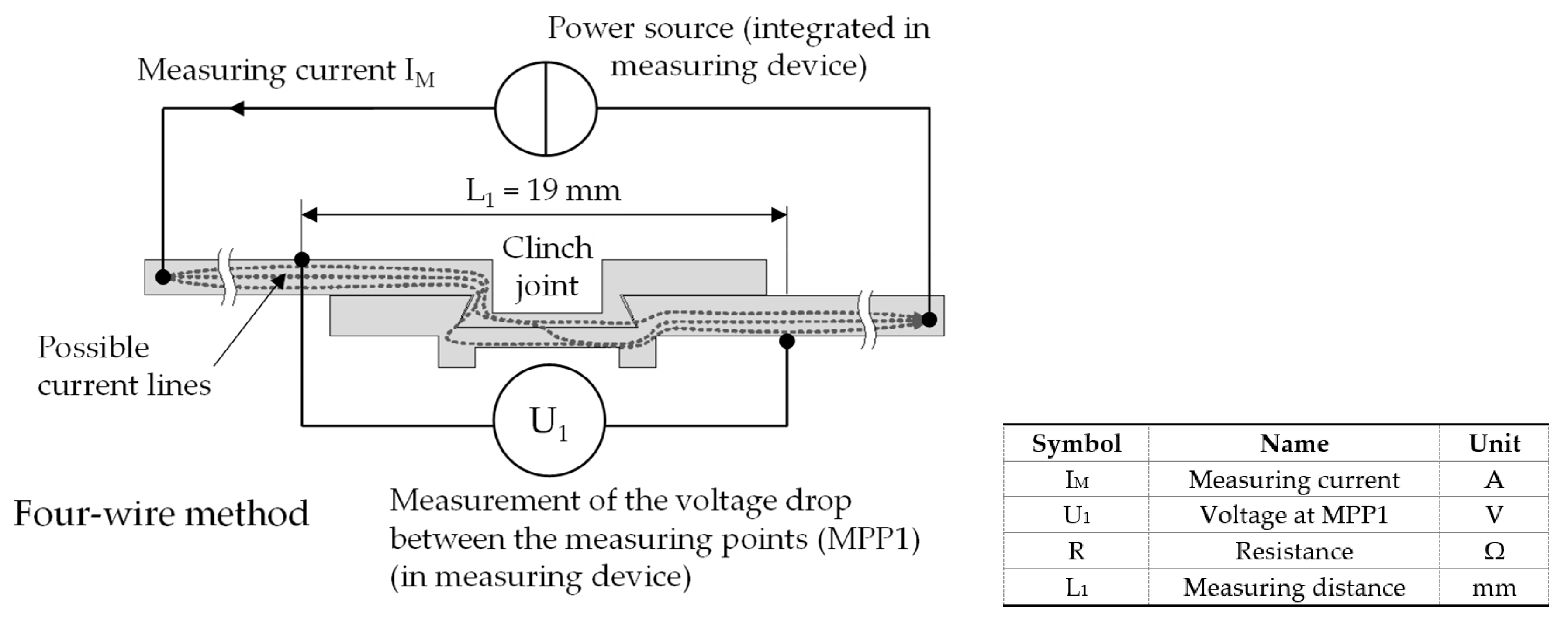
The connection resistance is determined using the four-wire measurement method shown in Figure 5 [27]. A defined current IM flows through the clinched components via two cables. The voltage drop U1 across the clinch point is measured over a defined distance. The resistance is calculated using Ohm’s law. Due to the measuring principle, the influence of the measuring cable resistance on the resistance measurement is greatly reduced. Only a very small, negligible current flows in the test leads. The voltage drop across the low-impedance test leads is negligible (compared to the voltage drop in the high-impedance voltmeter) [11]. According to [28], the measurement of electrical conductivity can be used as a check for the heat treatment condition. Jiang [29] uses the measurement of the electrical resistance with the four-wire-method at clinched joints as a quality inspection method.
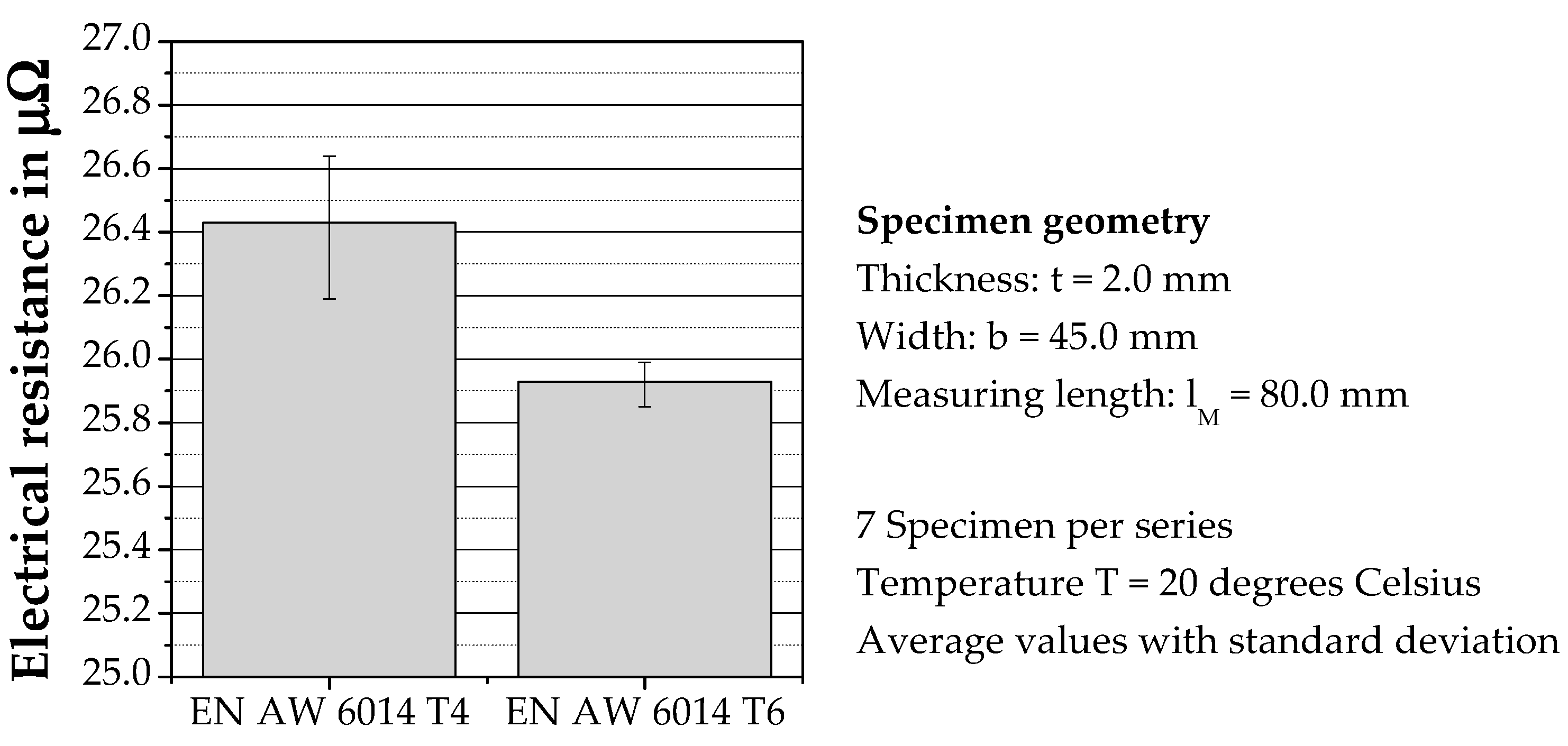
A comparison of the electrical resistances of the homogeneously flowed-through test material in the material states T4 and T6 with the same conductor cross sections and gauge lengths is shown in Figure 6. While the material resistance RM in the T4 state is 26.43 µΩ, the electrical resistance decreases to 25.93 µΩ in the T6 state due to precipitation hardening. Thus, there is a 7.9% reduction in electrical resistance compared to the T4 condition. The measurements in [11] for the material EN AW 6016 show a similar percentage decrease in resistance.
This means that the electrical conductivity of the base material is improved by heat treatment, as also explained in [30], using the aluminum layup EN AW 2024 and [31] for 6xxx aluminum conductors. Zhang et al. [32] state in their investigations that heat-treated conductors have a higher electrical conductivity compared to the non-heat-treated conductors made of Al-Mg-Si alloys. This improved conductivity should also affect the electrical resistance values of the clinch points.
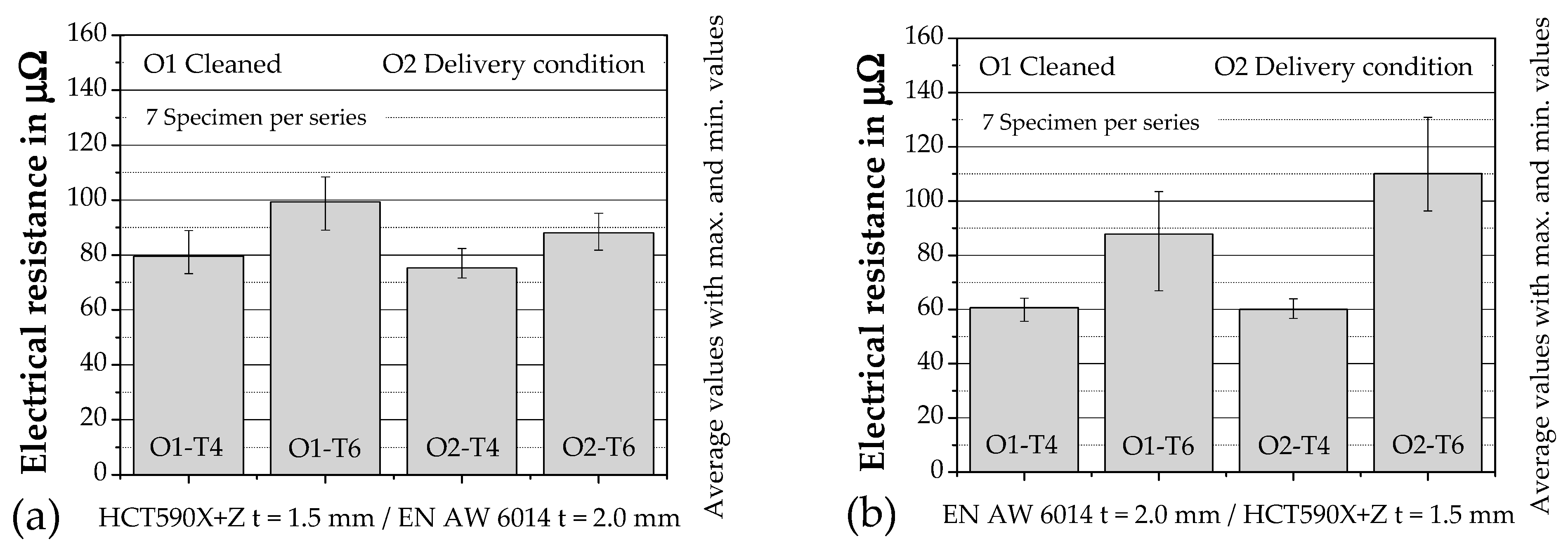
When comparing the electrical resistances, a higher electrical resistance is measured for all clinched samples after precipitation hardening than in the initial condition T4. In Figure 7a, when the aluminum is arranged as the die-side joining partner, a small influence is initially measurable when comparing the surface states. When comparing the heat treatment condition and in the cleaned condition (O1), an increase in the electrical resistances from R = 79.5 µΩ in condition T4 to R = 99.2 µΩ in condition T6 can be seen. Similarly, for the series joined in the as-delivered condition (O2), the electrical resistance increases after precipitation hardening from R = 75.3 µΩ in the T4 condition to R = 88.1 µΩ in the T6 condition. The increase in electrical resistances is due to the decrease in surface pressure between the joining partners is caused by the thermal load during precipitation hardening. In [33], Zhai describes the contact stiffness and electrical contact resistance on rough surfaces as a function of surface pressure. A change in the mechanical stress state at the interface of the joining partners as a result of the precipitation hardening process leads to a reduction in the actual contact area and thus to an increase in the electrical resistance of the clinched joint.
When reversing the joining direction with the aluminum material in the punch-side arrangement, the surface condition exerts only a minor influence on the contact behavior (Figure 7b). The influence of precipitation hardening, on the other hand, dominates the electrical contact behavior more clearly than in the series with the aluminum material arranged on the die side. The electrical resistance increases by 27.1 µΩ after precipitation hardening for the series with cleaned surface (O1), which corresponds to an increase of 44.9%. This is similarly true for the specimens with the surface condition (O2) “as-delivered”, with resistances increasing after precipitation hardening from 60.0 µΩ to 110.1 µΩ, corresponding to an increase of 83.5%. The scatter bands also increase after precipitation hardening of the aluminum material. Evaluating the electrical resistances further shows that the process of precipitation hardening affects the force-closure component of the binding mechanism. The mechanical stress reduction increases the electrical resistance, which corresponds to a reduction in the fraction of the force-closure component. The change in the inherent resistance of the aluminum material is negligible for the measured increases in the bond resistances.
3. Discussion
These comparison series show the influence of the different mechanical stress states of the clinch point. In the case of mixed joints, precipitation hardening leads, depending on the joining direction, to a variation the binding mechanism force-closure. A resulting material-closure can be excluded based on the resistances measured.
The deformed state of a material is unstable [17]. The strain hardening generated by the clinching process, which is inhomogeneously distributed in the clinching point, affects the residual stress state of the joint. This residual stress state is superimposed with load stresses and influences together with the mechanical properties the thermal and therefore the electrical properties as a function of the degree of deformation, the joining part material and the temperature. Gibmeier [16] shows that residual compressive stresses are present in both base materials when using closed dies in the range up to a distance of approx. 4–6 mm from the clinch joint. The applied process heat of 185 °C over a period of 20 min during precipitation hardening influences this residual stress state and, consequently, the force-closure component in the joint. The stresses during precipitation hardening at the clinch point caused by the difference in the coefficients of thermal expansion of the individual joining partners superimpose these residual stresses.
For the work carried out, it is first necessary to integrate the process chain passing through during component manufacture (Figure 1) into the investigations, since the process heat during the precipitation hardening process influences the bonding mechanisms present.
With the results of these test series and by taking into account the process chain (Figure 1) the influencing factors and dependencies shown in Figure 8 can indicate the changed force-closure component proportions within the clinched joints.
The process heat introduced during precipitation hardening influences the proportion of the binding mechanism force-closure within the clinch point. The form-closure component, on the other hand, is not influenced. The form-closure and force-closure binding mechanisms in clinched joints can be analyzed by taking a holistic view of the production process (joinability). The test methods of torsion testing and measurement of the electrical connection resistance are able to quantify the change in the force closure component. The two test methods are mutually independent as they depend on different physical principles and therefore quantify the force-closure component based on a torsional moment and electrical resistance. A higher torsional moment means a larger force-closure component, as does a lower electrical resistance.
Depending on the requirements of the joint—e.g., for mechanical tasks via the torsion test or electrical tasks via the resistance measurement—the joint can be designed via the description of the binding mechanisms. These results can be used for simulation of the individual clinching point or for a holistic view of the process chain.
4. Conclusions
A clinch joint can be described by the binding mechanism form- and force-closure. The same geometrical parameters for clinching tools, but different surface conditions lead to significant differences in the mechanical stress state and, as a result, in the force-closure component. The precipitation hardening process influences the mechanical stress state within the clinch joint (Δ force-closure component). The test methods torsion test and measurement of the electrical connection resistance can quantify a change in the force-closure component.
An altered force-closure component causes altered mechanical and electrical clinch point behavior. These investigations present the possibility of specifically influencing the force-closure component depending on the subsequent applications.
Based on these results, a higher mechanical and electrical load capacity of the clinching point can be achieved.
From the mechanical view, the testing method torsion test can describe these changes of the stress state within the clinch joint. As a result, the higher the torsional moment, the higher the force-closure component. The binding mechanism force-closure can be taken into account in a future clinch point design or an FEA simulation of the process chain.
When using clinch joints for contacting electrical conductors, the binding mechanism force-closure represents a dominant design variable for the current carrying capacity of the joint. A reduction of surface pressure between the joining partners at the clinch joint leads to an increasing electrical connection resistance caused by the reduced force-closure component. This increased joint resistance leads to a temperature increase in the clinch joint, which can lead to a joint failure from an electrical point of view.
By measuring the electrical resistance before and after precipitation hardening, this change in the force-closure component can be detected and taken into account by the electrical design of the joint with regard to long-term stable behavior.
Author Contributions
Conceptualization, U.F. and J.K.; Methodology, J.K.; Validation, U.F.; Investigation, J.K.; Data curation, J.K.; Writing—original draft preparation, J.K.; Writing—review and editing, U.F.; Supervision, U.F.; Project administration, U.F.; Funding acquisition, U.F. All authors have read and agreed to the published version of the manuscript.
Funding
This research was funded by the Deutsche Forschungsgemeinschaft (DFG, German Research Foundation)-TRR 285-Project-ID 418701707, subproject A04.
Data Availability Statement
All data generated in this study were included in this article.
Conflicts of Interest
The authors declare no conflict of interest.
References
- He, X. Clinching for sheet materials. Sci. Technol. Adv. Mater. 2017, 18, 381–405. [Google Scholar] [CrossRef] [PubMed] [Green Version]
- Groche, P.; Wohletz, S.; Brenneis, M.; Pabst, C.; Resch, F. Joining by forming—A review on joint mechanisms, applications and future trends. J. Mater. Process. Tech. 2014, 214, 1972–1994. [Google Scholar] [CrossRef]
- Lee, C.-J.; Kim, J.Y.; Lee, S.K.; Ko, D.C.; Kim, B.M. Design of mechanical clinching tools for joining of aluminium alloy sheets. Mater. Des. 2010, 31, 1854–1861. [Google Scholar] [CrossRef]
- Ewenz, L.; Kalich, J.; Zimmermann, M.; Füssel, U. Effect of different tool geometries on the mechanical properties of Al-Al clinch joints. Key Eng. Mater. 2021, 883, 65–72. [Google Scholar] [CrossRef]
- Eshtayeh, M.M.; Hrairi, M.; Mohiuddin, A.K.M. Clinching process for joining dissimilar materials: State of the art. Int. J. Adv. Manuf. Technol. 2016, 82, 179–195. [Google Scholar] [CrossRef]
- Abe, Y.; Kato, T.; Mori, K. Joining of aluminium alloy and mild steel sheets using mechanical clinching. In Materials Science Forum; Trans Tech Publications, Ltd: Stafa-Zurich, Switzerland, 2007; Volume 561-565, pp. 1043–1046. [Google Scholar] [CrossRef]
- Lee, C.-J.; Kim, J.Y.; Lee, S.K.; Ko, D.C.; Kim, B.M. Parametric study on mechanical clinching process for joining aluminum alloy and high-strength steel sheets. J. Mech. Sci. Technol. 2010, 24, 123–126. [Google Scholar] [CrossRef]
- Abe, Y.; Matsuda, A.; Kato, T.; Mori, K.I. Plastic joining of aluminium alloy and high strength steel sheets by mechanical clinching. Steel. Res. Int. 2008, 79, 649–656. [Google Scholar]
- Abe, Y.; Mori, K.; Kato, T. Joining of high strength steel and aluminium alloy sheets by mechanical clinching with dies for control of metal flow. J. Mater. Process. Technol. 2012, 212, 884–889. [Google Scholar] [CrossRef]
- Abe, Y.; Kishimoto, M.; Kato, T. Joining of hot-dip coated steel sheets by mechanical clinching. Int. J. Mater. 2009, 2, 291. [Google Scholar] [CrossRef]
- Füssel, U.; Kalich, J.; Großmann, S.; Schlegel, S.; Ramonat, A. Optimierung Umformtechnischer Fügeverfahren zur Kontaktierung Elektrischer Leiter. EFB Forschungsbericht Nr. 506; European Research Association for Sheet Metal Working: Hannover, Germany, 2019; ISBN 978-3867765596. [Google Scholar]
- Schweißbarkeit—Metallische Werkstoffe—Allgemeine Grundlagen; DIN-Fachbericht ISO/TR 581: 2007-04 (Deutsche Fassung); Beuth Verlag GmbH: Berlin, Germany, 2007.
- Riedel, F. Eigenschaftsverbesserung von Durchsetzfügeverbindungen durch die Kombination mit Stoffschluss; Shaker Verlag GmbH: Düren, Germany, 1997. [Google Scholar]
- Füssel, U.; Kalich, J.; Großmann, K.; Schlegel, S.; Schmid, J. Elektrisches Eigenschaftsprofil umformtechnischer Fügeverbindungen; EFB-Forschungsbericht Nr. 389; European Research Association for Sheet Metal Working: Hannover, Germany, 2014; ISBN 978-3-86776-432-2. [Google Scholar]
- Salamati, M.; Soltanpour, M.; Fazli, A.; Zajkani, A. Processing and tooling considerations in joining by forming technologies; part A—Mechanical joining. Int. J. Adv. Manuf. Technol. 2019, 101, 261–315. [Google Scholar] [CrossRef]
- Gibmeier, J.; Lin, R.; Odén, M.; Scholtes, B. Residual stress distribution around clinched joints. Mater. Sci. Forum 2002, 404–407, 617–622. [Google Scholar] [CrossRef]
- Gottstein, G. Physikalische Grundlagen der Materialkunde; Springer: Berlin/Heidelberg, Germany, 2007; ISBN 978-3-540-71104-9. [Google Scholar]
- Datasheet Automotive. Novelis Advanz™ 6F—e170; Novelis Global Automotive; Novelis AG: Kuesnacht, Switzerland, 2019.
- Product Information. CR330Y590T-DP (HCT590X + Z, HCT600XD, HC340XD); Salzgitter Flachstahl GmbH: Salzgitter, Germany, 2020.
- DVS-Merkblätter und Richtlinien Mechanisches Fügen; DVS-Fachbücher Band 153; DVS Media GmbH: Düsseldorf, Germany, 2009; ISBN 978-3-87155-230-4.
- Zähr, J. Einfluss des Oberflächenzustandes auf das Thermische Fügen von Aluminium; TUDpress Verlag der Wissenschaften Dresden: Dresden, Germany, 2011; ISBN 978-3-942710-28-2. [Google Scholar]
- Kogut, L.; Komvopoulos, K. Electrical contact resistance theory for conductive rough surfaces. J. Appl. Phys. 2003, 94, 3153–3162. [Google Scholar] [CrossRef]
- Kogut, L. Electrical performance of contaminated rough surfaces in contact. J. Appl. Phys. 2005, 97, 103723. [Google Scholar] [CrossRef]
- Böhme, H. Mittelspannungstechnik—Schaltanlagen Berechnen und Entwerfen, 2nd ed.; Huss Medien GmbH: Berlin, Germany, 2005; ISBN 978-3-341-01495-0. [Google Scholar]
- Schlegel, S.; Großmann, S.; Löbl, H.; Hoidis, M.; Kaltenborn, U.; Magier, T. Joint resistance of bolted copper-copper busbar joints depending on joint force at temperatures beyond 105 °C. In Proceedings of the 56th IEEE Holm Conference on Electrical Contacts, Charleston, SC, USA, 4–7 October 2010. [Google Scholar]
- Schlegel, S.; Großmann, S.; Kalich, J.; Füssel, U. Kontakt—und Langzeitverhalten umformtechnischer stromführender Verbindungen für den Einsatz in der E-Mobilität. In Proceedings of the Kontaktverhalten und Schalten-25, Fachtagung Albert-Keil-Kontaktseminar, Karlsruhe, Germany, 9–11 November 2019. [Google Scholar]
- Rieder, W. Elektrische Kontakte: Eine Einführung in ihre Physik und Technik; VDE-Verlag: Berlin, Germany, 2000; ISBN 9783800725427. [Google Scholar]
- Ostermann, F. Anwendungstechnologie Aluminium; Springer: Berlin/Heidelberg, Germany, 2007; ISBN 978-3-540-71196-4. [Google Scholar]
- Jiang, T.; Liu, Z.X.; Wang, P.C. Quality inspection of clinched joints of steel and aluminum. Int. J. Adv. Manuf. Technol. 2015, 76, 1393–1402. [Google Scholar] [CrossRef]
- Oliveira, P.J.; Melo, M.L.N.; Silva, R.S.M.; Caixeta, D.O. Relationship between Electrical Conductivity and the Stage of the Heat Treatments of Aging and Overaging of the Aluminum Alloy AA2024. In Materials Science Forum; Trans Tech Publications, Ltd: Stafa-Zurich, Switzerland, 2018; Volume 930, pp. 400–404. [Google Scholar] [CrossRef]
- Nikzad, K.S.; Javidani, M.; Maltais, A.; Chen, X. Investigation on electrical conductivity and hardness of 6xxx aluminum conductor alloys with different Si levels. In Proceedings of the 17th International Conference on Aluminium Alloys 2020 (ICAA17), Grenoble, France, 26–29 October 2020. [Google Scholar] [CrossRef]
- Zhang, J.; Ma, M.; Shen, F.; Yi, D.; Wang, B. Influence of deformation and annealing on electrical conductivity, mechanical properties and texture of Al-Mg-Si alloy cables. Mater. Sci. Eng. A 2018, 710, 27–37. [Google Scholar] [CrossRef]
- Zhai, C.; Hanaor, D.; Proust, G.; Brassart, L.; Gan, Y. Interfacial electro-mechanical behaviour at rough surfaces. In Extreme Mechanics Letters; Elsevier: Amsterdam, The Netherlands, 2016; Volume 9, pp. 422–429. [Google Scholar]
Figure 1.
Production process clinching of Al-Steel components.

Figure 2.
Local binding mechanisms (a) and geometric features (b) at clinch points.

Figure 3.
Torsion test setup (a) and characteristic testing curve (b).

Figure 4.
Torsion test by variation of joining direction and surface condition.

Figure 5.
Test setup electrical test.

Figure 6.
Material resistance of the test material before and after precipitation hardening.

Figure 7.
Electrical resistance by variation of joining direction and surface condition.

Figure 8.
Factors influencing the clinch connection along the process chain.


Table 1.
Chemical composition of the joining materials EN AW 6014 [18] and HCT 590X+Z [19] in weight %.
| EN AW 6014 | Si | Fe | Cu | Mn | Mg | Cr | Zn | Ti | V | Other Each | Other Total |
| 0.3–0.6 | max. 0.35 | max. 0.25 | 0.05–0.2 | 0.4–0.8 | max. 0.20 | max. 0.10 | max. 0.10 | max. 0.10 | max. 0.05 | max. 0.15 | |
| HCT 590X+Z | C | Si | Mn | P | S | Al Total | Cr + Mo | Nb + Ti | |||
| 0.15 | 0.75 | 2.50 | 0.04 | 0.01 | 0.015–1.500 | 1.400 | 0.150 | ||||
Table 2.
Design and dimensioning of the clinch joints investigated (seven specimens per series).
| Sheet Thickness in mm | Surface Condition | Micrograph | Tools A—Punch B—Die | Neck Thickness tn in mm | Undercut tu in mm | Bottom Thickness tb in mm |
|---|---|---|---|---|---|---|
|
Series 1 t1 = 2.0 t2 = 1.5 | Cleaned |  | A56100/BD8016 | 0.42 ± 0.03 | 0.23 ± 0.01 | 0.87 ± 0.01 |
|
Series 2 t1 = 2.0 t2 = 1.5 | Delivery Condition |  | A56100/BD8016 | 0.44 ± 0.03 | 0.24 ± 0.02 | 0.79 ± 0.01 |
|
Series 3 t1 = 1.5 t2 = 2.0 | Cleaned |  | ABY461850100/BB8008 | 0.39 ± 0.01 | 0.14 ± 0.02 | 1.00 ± 0.01 |
|
Series 4 t1 = 1.5 t2 = 2.0 | Delivery Condition |  | ABY461850100/BB8008 | 0.36 ± 0.02 | 0.14 ± 0.02 | 0.99 ± 0.01 |
Table 3.
Mechanical properties of EN AW 6014 [18].
Table 3.
Mechanical properties of EN AW 6014 [18].
| Rp0.2 in MPa | Rm in MPa | AG in % | A80 in % | Rp0.2/Rm | n5 | r10 | |
|---|---|---|---|---|---|---|---|
| T4 | ≤130 | ≥175 | ≥20 | ≥23 | ≤0.55 | ≥0.26 | ≥0.6 |
| T6 | ≥200 | ≥260 | ≥14 |
Publisher’s Note: MDPI stays neutral with regard to jurisdictional claims in published maps and institutional affiliations. |
© 2021 by the authors. Licensee MDPI, Basel, Switzerland. This article is an open access article distributed under the terms and conditions of the Creative Commons Attribution (CC BY) license (https://creativecommons.org/licenses/by/4.0/).
Share and Cite
MDPI and ACS Style
Kalich, J.; Füssel, U. Influence of the Production Process on the Binding Mechanism of Clinched Aluminum Steel Mixed Compounds. J. Manuf. Mater. Process. 2021, 5, 105. https://0-doi-org.brum.beds.ac.uk/10.3390/jmmp5040105
AMA Style
Kalich J, Füssel U. Influence of the Production Process on the Binding Mechanism of Clinched Aluminum Steel Mixed Compounds. Journal of Manufacturing and Materials Processing. 2021; 5(4):105. https://0-doi-org.brum.beds.ac.uk/10.3390/jmmp5040105
Chicago/Turabian StyleKalich, Jan, and Uwe Füssel. 2021. "Influence of the Production Process on the Binding Mechanism of Clinched Aluminum Steel Mixed Compounds" Journal of Manufacturing and Materials Processing 5, no. 4: 105. https://0-doi-org.brum.beds.ac.uk/10.3390/jmmp5040105