
FE-Simulation Based Design of Wear-Optimized Cutting Edge Roundings


1
Institute of Production Engineering and Machine Tools, Leibniz University Hannover, An der Universität 2, 30823 Garbsen, Germany
2
LMT Tools GmbH & Co. KG, Grabauer Str. 24, 21493 Schwarzenbek, Germany
*
Author to whom correspondence should be addressed.
J. Manuf. Mater. Process. 2021, 5(4), 126; https://0-doi-org.brum.beds.ac.uk/10.3390/jmmp5040126
Submission received: 1 November 2021
/
Revised: 18 November 2021
/
Accepted: 22 November 2021
/
Published: 25 November 2021
(This article belongs to the Topic Modern Technologies and Manufacturing Systems)
Abstract
:The performance of cutting tools can be significantly enhanced by matching the cutting edge rounding to the process and material properties. However, the conventional cutting edge rounding design is characterized by a significant number of experimental machining studies, which involve considerable cost, time, and resources. In this study, a novel approach to cutting edge rounding design using FEM-based chip formation simulations is presented. Based on a parameterized simulation model, tool temperatures, stresses and relative velocities can be calculated as a function of tool microgeometry. It can be shown that the external tool loads can be simulated with high agreement. With the help of these loads and the use of wear models, the resulting tool wear and the optimum cutting edge rounding can be determined. The final experimental investigations show a qualitatively high agreement to the simulation, which will enable a reduced effort design of the cutting edge in the future.
1. Introduction
Cutting edge preparation is state of the art in the manufacture of cutting tools. Knowledge of the influence of microgeometry on the application behavior of cutting tools plays a key role in a complete understanding of the process [1]. Cutting edge microgeometry is commonly described as an ideal arc with a radius of rβ. However, further investigations of rounded cutting edges depicted a symmetrical or asymmetrical shape. Denkena et al. developed the form-factor method (see Figure 1), which describes not only symmetrical but also asymmetrical cutting edge roundings with the parameters Sα, Sγ, ∆r, K and φ [2].
The interactions between the tool properties, the cutting parameters and the effects on the machining process are all influenced and thus determined by the cutting edge microgeometry [1]. In previous studies, it was shown that the mechanical load of the cutting wedge is influenced by the size of the cutting edge rounding. Wyen and Wegener [3] investigated the influence of symmetrical cutting edge geometries on process forces during TiAlV4 machining using orthogonal turning tests. FEM simulations by Özel and Altan [4] and Ulutan et al. [5] showed the importance of a properly parameterized simulation model as well as the interaction between different cutting edge shapes and the changing thermomechanical tool loads. On the basis of Albrecht’s force model [6], the ploughing forces acting on the cutting edges and the coefficient of friction on the cutting surface were determined. A linear increase of both values could be recorded with the cutting edge rounding. Denkena et al. [7] present similar results for the machining of AISI1045. In addition, it could be shown that the process forces are primarily determined by the cutting edge segment on the flank face Sα, whereas the cutting edge segment on the rake face Sγ can be neglected with regard to the process forces. Investigations by Karpat and Özel also showed that the feed forces are influenced significantly more than the cutting forces [8].
The resulting process forces are directly related to the plastomechanical material flow in front of the cutting edge [1]. Shaw [9] reports that the use of rounded cutting edges is associated with the formation of a pronounced stagnation zone in the area of the cutting edge rounding. The material is increasingly pressed under the flank surface and undergoes considerable deformation.
Furthermore, the cutting edge rounding also determines the resulting wear and the stability of the cutting edge and consequently the tool life during turning [7], drilling [10] and milling [11]. In general, a stabilization of the cutting wedge can be observed when increasing the cutting edge rounding. This can be attributed to the induction of more favorable stress conditions in the cutting wedge, which counteract crack initiation and thus considerably reduce the probability of cutting edge breakouts [12]. Furthermore, the position of the maximum stress is influenced by the size of the rounding and the ratio of Sα and Sγ. For asymmetrically rounded cutting edges with K > 1, the position of the maximum stresses shifts in the direction of the tool tip [8]. The size and asymmetry of the cutting edges also influences the wear characteristics on the rake face and flank face. During machining of AISI 1045, Bassett [13] showed that an increase of the cutting edge section Sγ leads to an earlier initiation of the crater wear with constant Sα. The specific shape of the cutting edge rounding, which in this case is predominantly inclined towards the rake face, leads to a higher thermal load and thus promotes crater wear. The tilting of the cutting edge to the flank face, on the other hand, results in an increase in flank wear.
In addition to experimental investigations, simulative approaches are increasingly being pursued to generate a deeper understanding of the interrelationships involved in machining with rounded cutting edges. Of particular interest in this context are chip formation simulations based on the finite element method (FEM). Based on such simulations, results can be generated that can only be achieved with considerable effort using experimental methods. The use of an FEM-based chip formation simulation enables the analysis of chip formation in the cutting edge area and the resulting tool load with high spatial and temporal resolution. In accordance with experimental results, Denkena et al. [14] showed that the stagnation zone increasingly expands with the enlargement of the cutting edge rounding. Bassett [13] carried out further simulative investigations on the material flow in front of the cutting edge. It could be shown that the stagnation zone is much more pronounced when using cutting edges with K = 2 than with K = 0.5. Heckmann [15] investigated the influence of the cutting edge microgeometry on the resulting local tool wear along the cutting edge profile of uncoated cemented carbide tools using FE-based chip formation simulations. The wear rate was calculated by coupling the Usui et al. wear rate model [16] with the chip formation simulation. In order to take into account the progressive wear-related geometry change and the associated change in tool load in the simulation, the approach proposed by Yen et al. [17] was applied. Tiffe et al. [18] utilized the Usui wear rate, which was calculated based on a two-dimensional simulation approach for the machining of nickel-based alloys, as an optimization criterion for the design of cutting edge geometry.
Despite the efforts made to date in researching the cause–effect relationships when using rounded cutting edges, a holistic approach to their design is not yet available. Therefore, this paper presents an experimental–analytical approach for the prediction of discontinuous failure due to cutting edge fracture as well as a simulative approach for the prediction of continuous wear. First, the normal stresses based on material properties were determined. This provides the basis for the comparison of the simulation regarding the mechanical loads for different materials. Secondly, the simulation was adapted with regard to the normal stresses, the friction coefficient and the material model. Then, the simulation was used to predict the wear behavior, by linking the tool load with wear rate models, and was validated in experimental studies.
2. Materials and Methods
2.1. Experimental Setup
2.1.1. Planing
The experimental machining studies were carried out on a planing test rig with integrated linear direct drive (see Figure 2), which enables cutting speeds of up to 180 m/min. The process forces were measured using a Kistler type 9257B multicomponent dynamometer and Kistler type 5015 charge amplifiers. The chip formation was analysed by means of a high speed camera Photron Fastcam SA5 and a mounted zoom lens by Navitar. When recording moving bodies perpendicular to the optical axis of the camera system, the exposure time required to avoid motion blur depends on the relative speed between the camera and the sample and thus the applied cutting speed. To avoid motion blur, very low exposure times are required. This places high demands on the light intensity to be provided.
A Xenon cold light by Karl Storz type Techno light 270 was used in order to ensure a sufficient brightness. For the measurement of the contact length, a frame rate of 16,000 fps, with a field of view of 512 × 512 pixels, was set. Further investigations of the material flow in the shear zone were carried out using a framerate of 40,000 fps and a reduced field of view of 320 × 256 pixels. In both cases, the setting was optimized to the requirements of the parameters to be determined with respect to temporal and spatial resolutions. All planing investigations were repeated twice.
2.1.2. Turning
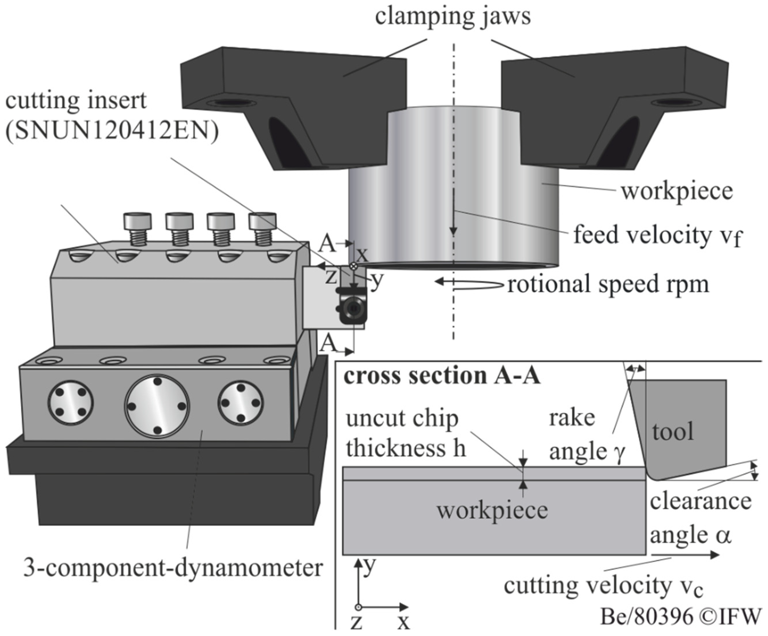
In order to parameterize the wear rate model and to validate the wear simulations, experimental orthogonal coolant-free turning tests were carried out. For this purpose a CNC vertical turning machine of type DMG-GILDEMEISTER CTV 400 was used. The test setup was adopted from [19] and is shown in Figure 3. For the cutting tests cemented carbide tools (WC-6Co, ultrafine grain) of the geometry SNUN120412EN were applied. To analyze the influence of the cutting edge rounding, 10 different cutting edge microgeometries were adjusted by means of brushes. For this purpose, three symmetrical cutting edge geometries were used to parameterize the wear rate model. The asymmetrical geometries were utilized to validate the wear rate model (see Table 1).
AISI4140 steel in hot-annealed condition was used as workpiece material. The mechanical properties are shown in Table 2. Constant process parameters (vc = 150 m/min, h = 0.1 mm, b = 3 mm) were used during all investigations. A rake angle of α = −6° and a clearance angle of γ = 6° were applied. A 3-component dynamometer type Kistler 9129AA measured process forces. All turning investigations were repeated twice. For the detection of the width of flank wear land VBmax a digital microscope Keyence VHX-5000 was used and the mean value of the investigations was determined. Furthermore, a more detailed analysis of the underlying wear mechanisms was carried out by means of Scanning Electron Microscopy (SEM).
2.2. Simulation Setup
The 2-dimensional orthogonal chip-forming simulations are performed on the basis of the finite element method (FEM) using the commercial software Deform-2D version 11.2 from Scientific Forming Technologies Corporation (SFTC). The numerical calculation is carried out thermomechanically and is coupled based on the Lagrange formulation with an implicit time integration. The simulation depicts the cutting process in the wedge measurement plane of the orthogonal cut assuming plain strain conditions. Due to the large ratio of chip width b to chip thickness h in the experiment (b/h = 30), a lateral flow of the material is neglected. Due to the chosen Lagrangian approach, the nodes of the FE mesh are firmly connected to the physical structure of the material, which allows a change in the outer workpiece geometry and thus the formation of a chip. The mesh distortions occurring as a result of the plastic material deformations are continuously compensated by automatic remeshing. This is initiated both with a critical degree of distortion of the workpiece elements, as well as with a defined overlap of tool and workpiece elements. However, the interpolation of the state variables between old and newly formed mesh is associated with a reduction in the calculation accuracy or a smoothing of the state variables. Therefore, to minimize the necessary remeshing cycles, increased mesh densities with a reduced element size are selected in the primary and secondary shear zones.
In order to determine the local temperature load in the tool-chip contact zone, the heat transfer within the body is defined by conduction as well as at the boundaries to the environment by convection (convection coefficient λ = 20 W/m²K) and thermal radiation. In addition, the heat transfer in the contact zone between tool and chip is calculated as a function of the contact area A, the heat transfer coefficient h and the temperature difference ΔT of the adjacent surfaces. For simplification, a constant value of 100 W/m²K was set for the heat transfer coefficient.
The workpiece was defined as an elasto-plastic body whose flow behavior is described as a function of strain, strain rate and temperature by the phenomenological material model according to Johnson and Cook [20] with the parameters according to [21]. The flow stress curves as well as the mechanical (Table 2) and thermal material data (Table 3) of the investigated material were taken from the material database of Software Deform. The cutting tool had been defined as ideally rigid.
As a mechanical contact model, a hybrid friction model was applied. In order to investigate the influence of different material properties, the friction parameters (Friction coefficient µ und shear friction factor m) were kept constant. The shear friction factor was set to m = 1 and the coefficient of friction to µ = 0.7 [21].
Chip formation simulations typically produce different types of nonlinearities. These include material-related and geometric nonlinearities as well as nonlinearities in the boundary conditions. Material-related nonlinearity results, for example, are from the nonlinear relationship between stress and strain, and occur in particular during the transition from elastic and plastic material deformations. Further nonlinearities result from the change in the geometric condition of the participating bodies during the calculation, as well as due to contact loss occurring. As an algorithm for solving the nonlinear equation systems, therefore, the Newton–Raphson method is utilized. With this simulation, the experimental data were matched and the material models and friction parameters were adjusted to achieve sufficient simulation quality. Afterwards, a wear rate model can be parameterized with the help of the thermomechanical tool loads and the local tool wear. The linking between the chip formation simulation, from which the tool load is determined, and the wear rate model, which determines the resulting material removal, can be used to predict tool wear. By discretizing the wear progression over time, even longer tool life times can be simulated and the wear behavior predicted. With this simulation approach, the cutting length lc up to a maximum flank wear width of VBmax = 150 µm was simulated for the different cutting edge roundings and compared with the experimental investigations.
3. Results
3.1. Experimental Results
In order to simulate the tool wear according to Usui et al. [22], it is necessary to determine the thermomechanical tool load in the form of sliding velocity, temperature and the normal stresses at the cutting wedge. The normal stress is especially challenging for a comparison with the simulation due to the fact that the experimentally determined normal stresses are based on methods which do not represent the cutting process sufficiently accurately, for example by using split tools or stress–optical materials. As a result, the friction between material and tool has been influenced in particular. Bergmann therefore developed a method to determine the stresses at the cutting wedge based on the measured incremental process forces and contact lengths [23]. In order to consider all the materials, the normal stresses are shown for a cutting edge rounding of Sα = Sγ = 30 μm. Especially, the application of larger cutting edge roundings leads to the formation of the built up edges in planing of Al7075T6. Therefore, the calculation of the stresses is incorrect.
For the wear simulation, the influence of the cutting edge rounding on the normal stresses has to be determined. Hereof, Bergmann reveals that the normal stresses at the cutting edge rounding as well as on the rake face are slightly influenced in comparison to the tangential stresses [23]. However, it is well known that different wear rates result by machining various materials. Thus, knowledge the influence of the material properties on the normal stresses is necessary for the wear simulation for different materials. With this knowledge, the simulation can be compared with the resulting loads on the cutting wedge and can thus be used for the wear simulation for different materials.
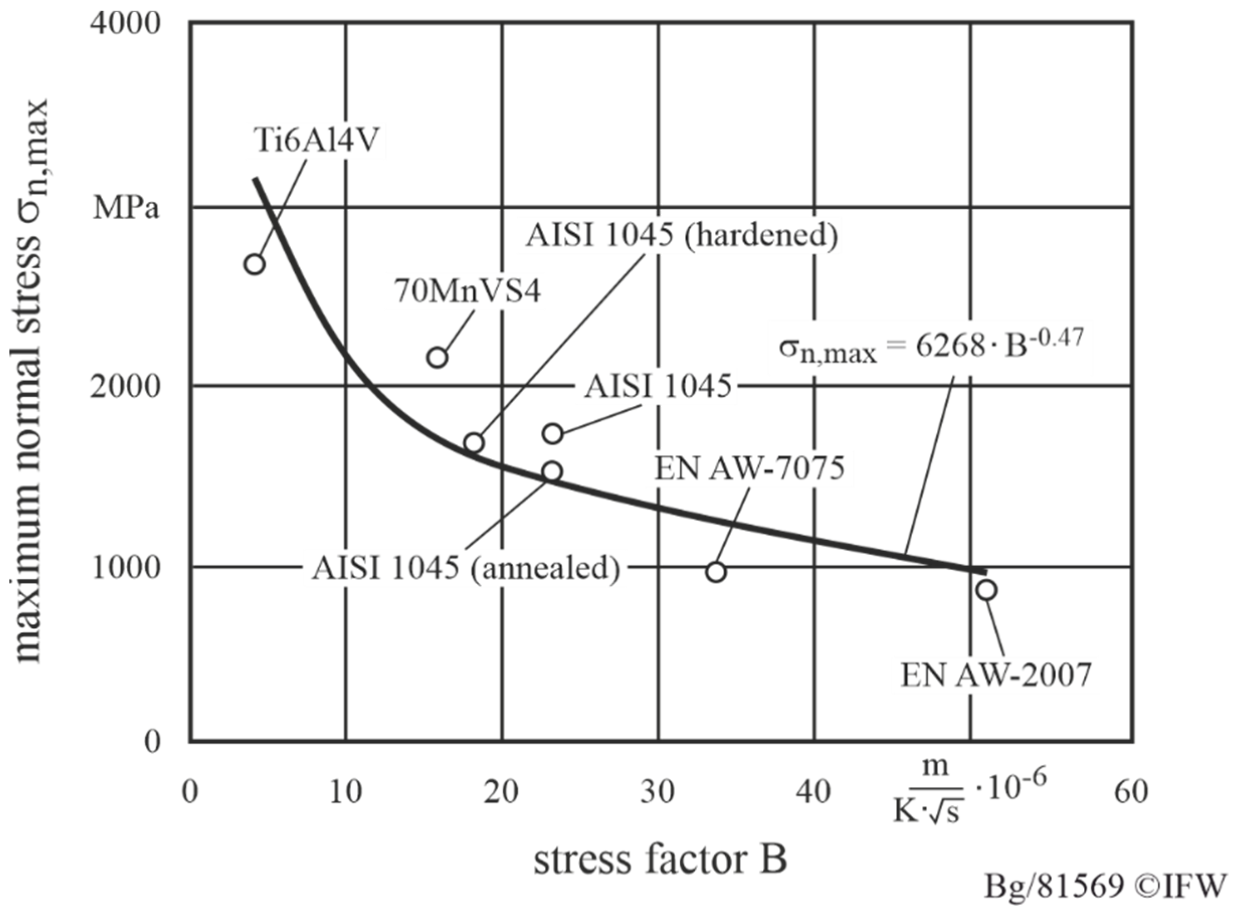
It is well known that the stresses on the rake face are influenced by the process forces as well as the contact length cl [24]. Therefore, in addition to the strength of the material, the change of the contact length cl on the rake face has to be considered. Thus, for the normal stress on the rake face, a relationship between the resulting maximum normal stresses at the rake face and a so-called “stress factor B” could be determined (Figure 4). The stress factor B is the quotient of the heat penetration coefficient b and the tensile strength Rm. The heat penetration coefficient b can be used to describe the heat flux density [25]. For materials with low heat penetration coefficients b, the tendency for thermal softening is reduced [24]. An increase in the tensile strength of the material tends to lead to an increased mechanical load on the cutting wedge. As presented in Figure 4, it can be seen that with decreasing stress factor B, the normal stresses on the rake face increases. This can be explained by the fact that with a decreasing heat penetration coefficient and an increasing tensile strength the chip formation is characterized by shear chip formation, as it is the case in machining Ti6Al4V.
This leads to a significant reduction of the contact length at the rake face. The result is an exponential increase of the normal stresses due to process forces, which appear on a significantly reduced surface. This effect occurs mainly in the case of hardened materials. Figure 4 illustrates this effect in the case of the heat-treated material AISI 1045. As a result, the normal stress increases as the material strength increases. The lowest normal stresses exhibit the aluminum alloys. Here, beside the lowest material strengths, in machining aluminum, the largest contact lengths occur [26]. Consequently, the normal stresses for the aluminum alloys decrease significantly in comparison with the ferrous metals. Altogether, it can be stated that by means of the stress factor B, the normal stresses for ferrous and non-ferrous metals at the rake face can be modelled and thus these findings can be used for the validation of the simulation. This knowledge is particularly necessary to prove the validity of the wear simulation for different materials.
3.2. Simulation Results
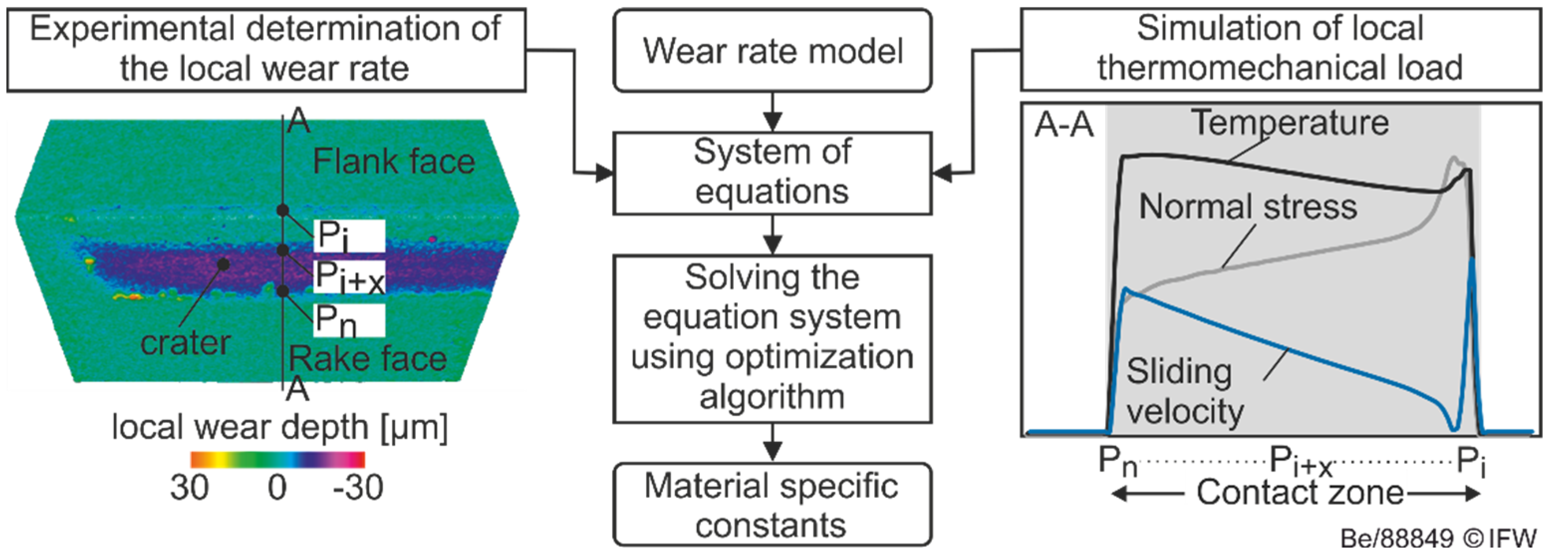
With the knowledge of the normal stresses, the validation of the simulation can be done more precisely in comparison by a validation based on process forces. This can be explained by the fact that the stresses, in comparison to the process forces, represents more exactly the load on the wedge. For a systematic design of cutting edge roundings, however, the temporal wear-related change of the microgeometry is of particular interest. A suitable way of predicting the continuous loss of material along the contact zone is the coupling of chip formation simulations and wear rate models [22]. The latter describe the functional relationship between the loss of material per unit of time and the local thermo-mechanical loads (see Figure 5). The overall objective of the following simulative investigations is therefore the verification of the application suitability of FE-based chip formation simulations for the prediction of continuous tool wear of different rounded cutting edges.
Based on the wear rate models investigated in the current state of knowledge, primarily the normal stresses, temperatures and relative velocities acting in the contact zone are analyzed in the following. The characteristic load collective in the contact zone is illustrated as an example in Figure 6 for an idealized unworn tool with a symmetrical cutting edge rounding of Sα = Sγ = 50 μm.
In accordance with the findings from the literature, the normal stress has a distinct maximum in the area of the cutting edge rounding. In this case, a linear decrease in the normal stress can be observed in the area of the rake and the flank face. The distribution of the simulated normal stress corresponds qualitatively to those proposed by Usui et al. [16] and those measured by Zorev and Uteschew [27] using rounded cutting edges.
The normal stress distribution in the region of the cutting edge is primarily affected by the presence of a so-called stagnation zone, which is characterized by low material flow rates. At the material separation point on the cutting edge rounding, the relative sliding speed is equal to zero. Starting from the separation point in the direction of the free surface, the relative velocity increases rapidly. This results in high velocity gradients. In the area of the global maximum on the flank face, the relative sliding velocity assumes values which approximately correspond to the applied cutting speed. On the rake face, the relative sliding velocity continuously increases up to the separation point of the chip on the rake face. However, due to the deflection of the material in the primary shear zone and the friction processes in the tool-chip interface, overall lower relative sliding velocities result than on the flank face.
The temperature profile shown is the result of the thermal energy converted during the machining in the primary shear zone, which is transmitted to the tool by conduction due to the temperature gradient between tool and chip, or the workpiece. Furthermore, the tool is subject to additional thermal loads as a result of friction processes in the contact zone. In this case, the converted thermal energy per unit time due to friction can be calculated from the product of the friction force and the relative speed. Following this connection, local temperature maxima result, in particular in the areas of high relative sliding speed, on the rake face and flank face. In contrast, the lowest temperatures are in the area of the cutting edge rounding. These fundamental relationships were recorded in different degrees of severity for all of the materials investigated.
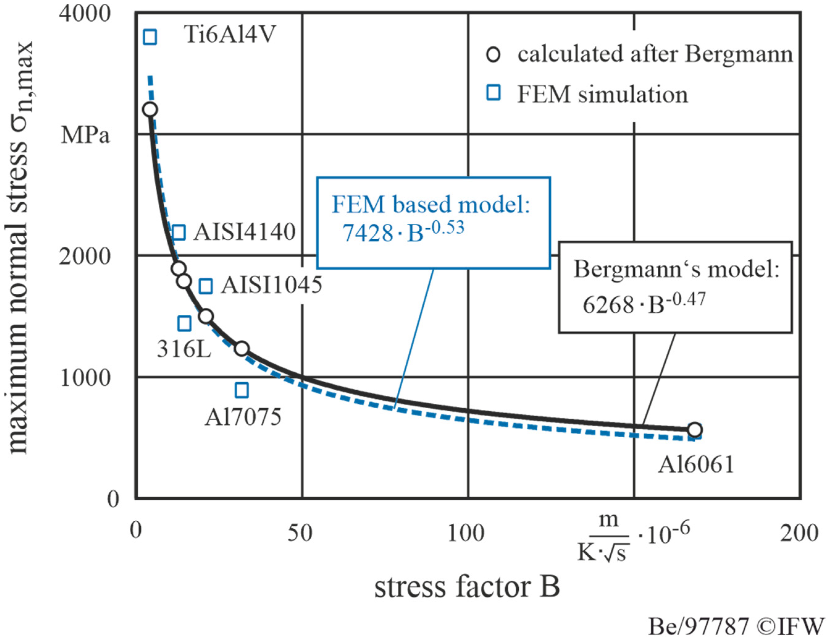
In order to validate the simulated maximum normal stresses, a comparison of simulated values with the experimental data calculated by Bergmann is shown in Figure 7.
Here, the maximum normal stress is described by means of a power function depending on the stress factor B. The stress factor B results from the quotient of the heat penetration coefficient b and the tensile strength Rm.
Based on the results, a mean deviation of 17 % can be observed with regard to the magnitude of the maximum normal stress. The material-specific deviations can be traced back to uncertainties regarding the choice of the material model of the workpiece. However, over the entirety of the examined materials, a high degree of consistency of the derived power functions can be determined. Based on the results it can be stated that the influence of the material properties on the maximum normal stresses in the contact zone is approximated with sufficient accuracy.
The influence of different material properties on the stress distribution in the contact zone between tool and chip is shown in Figure 8.
It can be seen that the normal stress curves differ significantly with respect to their distribution and magnitude along the rake face. This can be explained by differences regarding the contact length. It can be stated that the contact length during machining of TiAl6V4 is significantly lower compared to Al7075T6 and AISI1045. This is primarily caused by the segmented chip formation in the simulation, which was induced by implementing the Cockroft and Latham fracture criteria [28] into the simulation model. Significant differences were also observed with regard to the normal stress in the area of the cutting edge rounding. In the case of the TiAl6V4 alloy, the induced force components were concentrated in the area of the cutting edge. This results in significantly increased normal stresses when the normal forces were applied to the contact surface.
Due to the cyclic shearing of the chip segments, the normal stress distribution during the machining of the TiAl6V4 alloy had a temporally periodic character. Figure 9 shows the stress distributions during the different phases of segmented chip formation. The beginning of the compression phase was characterized by a continuous increase in the contact length with a simultaneous decrease in the normal stress. As the compression progresses, shear stress was induced along the primary shear zone caused by local material failure. During the shearing off of the chip segment, the contact length decreased significantly, which resulted in increased normal stresses in the area of the cutting edge rounding. Due to the complexity of the segmented chip formation with respect to the thermomechanical load and the resulting tool wear, such processes were not considered further in the subsequent simulative analyses of the wear behavior.
In addition to the material properties, the characteristics of the normal stresses were influenced by the shape of the cutting edge rounding, illustrated in Figure 10 for machining of AISI4140. Here it was evident that the increase in the cutting edge rounding did not significantly influence the amount of maximum normal stress. By increasing Sα/Sγ from 30 to 100 µm, the maximum normal stress was decreased by only 16%. However, the increase in the cutting edge rounding lead to a significant widening of the range of maximum normal stresses in the area of the cutting edge rounding.
In addition to the size of the cutting edge rounding, the load on the cutting wedge is essentially determined by the tilting of the rounding to the rake face or flank face. Figure 11 therefore compares different asymmetrical cutting edges with regard to their effect on the output values required for the wear calculation according to Usui.
In the case of a cutting edge rounding with K = 0.5, the maximum temperature shifts in the direction of the flank face. This can be attributed to the significantly increased relative sliding speeds as well as the higher contact length in the area of the flank face. In addition, the range of maximum normal stresses is much more pronounced on the flank face. Due to the higher normal stress components in the feed direction, it can be expected that the cutting wedge will be subjected to less bending stress than with K = 2. Consequently, a reduction in the tendency of the cutting edge to break out can be assumed. Regarding the distribution of the relative sliding velocity along the contact zone, it becomes clear that the stagnation zone for K = 2 is clearly extended further in the direction of the rake face. This results in significantly lower temperatures in the area of the cutting edge rounding and the adjacent rake face. Only minor differences can be observed with regard to the relative sliding velocity on the rake face at the point of the chip detachment.
To visualize the local thermomechanical load spectrum as a function of the cutting edge microgeometry, so-called load maps were developed (see Figure 12).
These provide information about the load at any point along the contact zone and serve as input variables for the calculation of the local wear rate according to Usui’s wear equation. The load maps were calculated based on 10 support points using the Delauney triangulation algorithm. Three points each form a triangle in which a linear interpolation of the respective output quantity takes place. For the calculation of the flank wear the local loads in the area of the flank face are used, which are exemplarily shown in Figure 12 for an unworn tool.
Since the normal stress at the flank face is homogenously distributed and approximately identical for the investigated cutting edge geometries, the relative sliding velocity and the temperatures are focused in Figure 12. The results indicate that the calculated temperatures have a high correlation with the relative sliding velocities. This can be attributed to the already described effect of the increasing frictional heat development at high relative sliding velocities. Furthermore, it becomes clear that the temperatures increase significantly with the increase of Sα/Sγ, especially for cutting edges with K < 1. The further validation of the simulated sliding velocity as well as the tool temperature in comparison to experimental results considering the adapted simulation model is presented in detail in the works of Breidenstein et al. [29] and Denkena et al. [30] For an accurate prediction of the resulting wear, a parameterization of the wear rate model has to be carried out for every workpiece/tool combination. Since these investigations are an absolute comparison of the wear behavior of different cutting edge microgeometries with the same workpiece/tool combination, this can be neglected. Therefore the constants were adopted from the work of Binder et al. [31,32,33]
4. Wear Simulation of Rounded Cutting Edges
The basis for the simulative reproduction of the continuous wear progress with progressive geometry change is the coupling between chip formation simulations and wear rate models. Due to the implementation of the parameterized wear model in the FE-based chip formation simulation, the wear-related material removal of the tool can be determined both spatially and temporally. The previous obstacle of low time efficiency of simulation can be eliminated by an approach based of the work of Yen et al. [34] The approach is shown in Figure 13.
In this approach, the tool life is discretized into a finite number of time steps. Then, a chip formation simulation is performed for the first time step and the thermomechanical load is determined with the help of the adapted material and friction models. These are the input variables of the parameterized wear model with which the tool wear can be determined for this time step. Using a node description of the FE mesh in cartesian coordinates, the material removal can be converted into a node displacement. The assumption of a constant stress in the quasi-stationary state is assumed for the respective time step. The new tool geometry, including the tool wear, is then used for the next chip formation simulation after a time step Δt. This simulation cycle can be repeated until a certain wear criterion occurs.
To validate the approach, the tool life of the different cutting edge roundings from Table 1 was simulated with the previously parameterized chip formation simulation and wear models up to a maximum flank wear width of VBmax = 150 µm. Figure 14 shows tool life maps of the different cutting edge microgeometries, in which the maximum tool life is color-coded. Experimental results required one week of testing, compared to two days of simulation data generation.
The tool life has been simulated once and determined once in experimental turning tests. During the tests, cutting edge roundings smaller than 40 µm showed cutting edge chipping, which limited the tool life. However, these geometries could also be identified as a minimum in the simulations. The maximum tool life could be identified both simulatively and experimentally at K < 1. In the simulation the optimized rounding is Sα = 100 µm and Sγ = 50 µm, while in the experiment the highest tool life occurred at Sα = 70 µm and Sγ = 50 µm. The difference between simulated and experimental tool life is 12.3 %. Thus, with the aid of a precise parameterization of the chip formation simulation and wear models as well as the discretization approach, the tool wear behavior can be simulated with sufficient accuracy. Based on these findings, a wide range of different microgeometries can be simulated whose experimental investigations would be very time- and cost-intensive. Based on the validation, the benefits of the simulation for the prediction of the tool wear or the tool design can be illustrated once again, whereby an exact adaptation of the modelling is necessary beforehand. The modelling of the stress distribution at the cutting wedge makes this possible.
5. Conclusions
On the basis of the investigations, the following conclusions can be drawn.
- With regard to the maximum normal stresses, Bergmann’s findings regarding the relationship between the workpiece properties and the normal stresses were confirmed.
- The latter is an essential input variable for common wear rate models for the simulative calculation of tool wear.
- Friction is the main influencing factor on temperature, relative sliding speed and contact length, which significantly influences the wear calculation.
- The use of adapted friction and material models in combination with the discretization of the operating time allows a precise prediction of tool wear.
- A combined approach of a parameterized chip formation simulation and tool wear model allows the calculation of tool wear depending on the used cutting edge rounding.
- As a result, the wear-optimized cutting edge rounding can be determined and evaluated during experimental investigations.
The systematic use of simulative approaches offers the potential to successively substitute experimental machining investigations, which are usually associated with a high consumption of time, costs and resources. However, there is still a need for research into the industrial application of chip formation simulations in machining. These concerns, for example, mechanisms such as friction and wear in dependence as well as the influence of cooling lubricants. A major obstacle for the objective-oriented use of chip formation simulations is still the lack of availability of generally valid friction models and data sets for their parameterization. Further investigation should also consider the influence of the tool-coating properties on the friction behavior. In order to further increase the acceptance of simulations on a sustained basis, a continuous improvement of accuracy and reliability is necessary, while at the same time ensuring an appropriate calculation time.
Author Contributions
Conceptualization, B.B. and B.D.; methodology, B.B. and S.B.; software, S.B.; validation, B.B., S.B. and T.P.; investigation, B.B. and S.B.; data curation, B.B. and S.B.; writing—original draft preparation, S.B. and T.P.; writing—review and editing, all authors; visualization, S.B. and T.P.; supervision, B.B. and B.D.; project administration, S.B.; funding acquisition, B.D. All authors have read and agreed to the published version of the manuscript.
Funding
This research was funded by the Deutsche Forschungsgemeinschaft (DFG), reference number DE447/71–2. The authors would also like to thank the “Sieglinde Vollmer Stiftung” for the financial support of this research work.
Data Availability Statement
The data presented in this study are available on request from the corresponding author.
Conflicts of Interest
The authors declare no conflict of interest. The funders had no role in the design of the study; in the collection, analyses, or interpretation of data; in the writing of the manuscript, or in the decision to publish the results.
References
- Denkena, B.; Biermann, D. Cutting Edge Geometries. CIRP Ann. Manuf. Technol. 2014, 63, 631–653. [Google Scholar] [CrossRef]
- Denkena, B.; Reichstein, M.; Brodehl, J.; de Leon Garcia, L. Surface Preparation, Coating and Wear Performance of Geometrical Defined Cutting Edges. Manuf. Eng. 2005, 5, 43–51. [Google Scholar]
- Wyen, C.-F.; Wegener, K. Influence of cutting edge radius on cutting forces in machining titanium. CIRP Ann. 2010, 59, 93–96. [Google Scholar] [CrossRef]
- Özel, T.; Altan, T. Determination of workpiece flow stress and friction at the chip tool contact for high-speed cutting. Int. J. Mach. Tools Manuf. 2000, 47, 133–152. [Google Scholar] [CrossRef]
- Ulutan, D.; Lazoglu, I.; Dinc, C. Three-dimensional temperature predictions in machining processes using finite difference method. J. Mater. Process. Technol. 2009, 209, 1111–1121. [Google Scholar] [CrossRef]
- Albrecht, P. New Developments in the Theory of the Metal-Cutting Process. The Ploughing Process in Metal Cutting. Trans. ASME 1960, 82, 348–357. [Google Scholar]
- Denkena, B.; Lucas, A.; Bassett, E. Effects of the cutting edge microgeometry on tool wear and its thermo-mechanical load. CIRP Ann. 2011, 60, 73–76. [Google Scholar] [CrossRef]
- Karpat, Y.; Özel, T. Mechanics of high speed cutting with curvilinear edge tools. Int. J. Mach. Tools Manuf. 2008, 48, 195–208. [Google Scholar] [CrossRef]
- Shaw, M.C. Metal Cutting Principles, 2nd ed.; Oxford University Press: New York, NY, USA, 2005. [Google Scholar]
- Biermann, D.; Terwey, I. Cutting edge preparation to improve drilling tools for HPC processes. CIRP J. Manuf. Sci. Technol. 2008, 1, 76–80. [Google Scholar] [CrossRef]
- Aurich, J.C.; Zimmermann, M.; Leitz, L. The preparation of cutting edges using a marking laser. Prod. Eng. 2011, 5, 17–24. [Google Scholar] [CrossRef]
- Shatla, M.; Kerk, C.; Altan, T. Process modeling in machining. Part II: Validation and applications of the determined flow stress data. Int. J. Mach. Tools Manuf. 2001, 41, 1659–1680. [Google Scholar] [CrossRef]
- Bassett, E. Belastungsspezifische Auslegung und Herstellung von Schneidkanten für Drehwerkzeuge. Ph.D. Thesis, Leibniz Universität Hannover, Hanovra, Germany, 2014. [Google Scholar]
- Denkena, B.; Köhler, J.; Mesfin, M. Influence of the cutting edge rounding on the chip formation process. Prod. Eng. 2012, 6, 329–338. [Google Scholar] [CrossRef]
- Heckmann, L. Systematische Analyse der Schneidkantenarchitektur Mithilfe der Finite-Elemente-Methode. Ph.D. Thesis, Universität Kassel, Kassel, Germany, 2010. [Google Scholar]
- Usui, E.; Shirakashi, T.; Kitagawa, T. Analytical prediction of cutting tool wear. Wear 1984, 100, 129–151. [Google Scholar] [CrossRef]
- Yen, Y.-C.; Söhner, J.; Lilly, B.; Altan, T. Estimation of toolwear in orthogonal cutting using the finite element analysis. Int. J. Mach. Sci. Technol. 2004, 146, 82–91. [Google Scholar]
- Tiffe, M.; Aßmuth, R.; Saelzer, J.; Biermann, D. Investigation on cutting edge preparation and FEM assisted optimization of the cutting edge micro shape for machining of nickel-base alloy. Prod. Eng. 2019, 13, 459–467. [Google Scholar] [CrossRef]
- Beblein, S.; Breidenstein, B.; Denkena, B. On the thermal insulation effect of PVD-AlCrN-coated cutting tools in continuous turning of AISI 4140. In Proceedings of the 13th International Conference “THE-A-Coatings” in Manufacturing Engineering 2017, Thessaloniki, Greece, 5–6 October 2017; pp. 53–61. [Google Scholar]
- Johnson, G.R.; Cook, W.H. A constitutive model and data for metals subjected to large strain, high strain rates and high temperatures. In Proceedings of the 7th International Symposium on Ballistics, Hague, The Netherlands, 19–21 April 1983; pp. 541–547. [Google Scholar]
- Beblein, S.; Breidenstein, B.; Denkena, B.; Pusch, C.; Hoche, M.; Oechsner, M. Thermomechanical coating load in dependence of fundamental coating properties. Procedia CIRP 2017, 58, 25–30. [Google Scholar] [CrossRef] [Green Version]
- Usui, E.; Hirota, A.; Masuko, M. Analytical Prediction of Three Dimensional Cutting Process–Part 3: Cutting Temperature and Crater Wear of Carbide Tool. Trans. ASME 1978, 100, 222–228. [Google Scholar] [CrossRef]
- Bergmann, B.; Grove, T. Basic principles for the design of cutting edge roundings. CIRP Ann. Manuf. Technol. 2018, 67, 73–78. [Google Scholar] [CrossRef]
- Amor, R.B. Thermomechanische Wirkmechanismen und Spanbildung bei der Hochgeschwindigkeitszerspanung. Ph.D. Thesis, Universität Hannover, Hannover, Germany, 2003. [Google Scholar]
- Baehr, H.D.; Stephan, K. Wärmeleitung und–Diffusion. In Wärme-Und Stoffübertragung; Springer: Berlin, Germany, 2013; Volume 8, pp. 121–311. [Google Scholar]
- Bergmann, B. Grundlagen zur Auslegung der Schneidkantenverrundung. Ph.D. Thesis, Leibniz Universität Hannover, Hannover, Germany, 2017. [Google Scholar]
- Zorev, N.N.; Uteschew, M.H. Untersuchung der Kontaktspannungen auf den Arbeitsflächen des Werkzeugs mit einer Schneidenabrundung. Ann. CIRP 1971, 20, 31–32. [Google Scholar]
- Cockroft, M.G.; Latham, D.J. Ductility and the workability of metals. J. Inst. Met. 1968, 96, 33–39. [Google Scholar]
- Breidenstein, B.; Denkena, B.; Heckemeyer, A.; Beblein, S. Correlation between coating properties and thermal load of CrAlN-coated cutting tools. Defect Diffus. Forum 2020, 404, 53–60. [Google Scholar] [CrossRef]
- Denkena, B.; Krödel, A.; Beblein, S. A novel approach to determine the velocity dependency of the friction behavior during machining by means of digital particle image velocimetry (DPIV). Int. J. Manuf. Sci. Technol. 2021, 32, 81–90. [Google Scholar] [CrossRef]
- Binder, M.; Klocke, F.; Lung, D. Tool wear simulation of complex shaped coated cutting tools. Wear 2015, 330–331, 600–607. [Google Scholar] [CrossRef]
- Binder, M.; Klocke, F.; Doebbeler, B. An advanced numerical approach on tool wear simulation for tool and process design in metal cutting. Simul. Model. Pract. Theory 2017, 70, 65–82. [Google Scholar] [CrossRef]
- Binder, M. Mechanismenbasierte Verschleißsimulation zur Integrierten Werkzeug-und Prozessauslegung. Ph.D. Thesis, RWTH Aachen, Aachen, Germany, 2017. [Google Scholar]
- Yen, Y.-C.; Söhner, J.; Weule, H.; Schmidt, J.; Altan, T. Estimation of tool wear of carbide tool in orthogonal cutting using the FEM simulation. Int. J. Mach. Sci. Technol. 2002, 6, 467–486. [Google Scholar] [CrossRef]
Figure 1.
Characterization of the cutting edge microgeometry [2].
Figure 1.
Characterization of the cutting edge microgeometry [2].

Figure 2.
Experimental setup for planing investigations.

Figure 3.
Experimental setup for turning investigations.

Figure 4.
Material-based modelling of the load stresses on the rake face.

Figure 5.
Parameterization of the wear rate model.

Figure 6.
Simulated tool load during machining of AISI4140.

Figure 7.
Validation of the simulated maximum normal stresses as a function of the workpiece properties.
Figure 7.
Validation of the simulated maximum normal stresses as a function of the workpiece properties.

Figure 8.
Simulated material specific normal stress distribution.

Figure 9.
Phases of segmented chip formation and corresponding normal stress distribution during machining of TiAl6V4.
Figure 9.
Phases of segmented chip formation and corresponding normal stress distribution during machining of TiAl6V4.

Figure 10.
Simulated normal stress distribution depending on the cutting edge rounding during machining of AISI4140.
Figure 10.
Simulated normal stress distribution depending on the cutting edge rounding during machining of AISI4140.

Figure 11.
Effect of asymmetric rounded cutting edges on the thermomechanical and kinematic load during machining of AISI4140.
Figure 11.
Effect of asymmetric rounded cutting edges on the thermomechanical and kinematic load during machining of AISI4140.

Figure 12.
Thermal and kinematic load maps as a function of cutting edge segments Sα and Sγ during machining of AISI4140.
Figure 12.
Thermal and kinematic load maps as a function of cutting edge segments Sα and Sγ during machining of AISI4140.

Figure 13.
Procedure for simulating the tool life time.

Figure 14.
Comparison between simulated and experimental tool life time.


Table 1.
Cutting edge microgeometries.
| Cutting Edge Segment | K = 1 | K > 1 | K < 1 | |||||||
|---|---|---|---|---|---|---|---|---|---|---|
| Sα | 10 | 30 | 50 | 100 | 30 | 50 | 70 | 50 | 70 | 100 |
| Sγ | 10 | 30 | 50 | 100 | 50 | 70 | 100 | 30 | 50 | 70 |
Table 2.
Mechanical material properties used in the simulation.
| Workpiece | Tensile Strength (MPa) | Young’s Modulus (GPa) | Poisson’s Ratio | Thermal Expansion (10−6 °C) | ||||||
|---|---|---|---|---|---|---|---|---|---|---|
| 20 °C | 500 °C | 1000 °C | 20 °C | 500 °C | 1000 °C | constant | 20 °C | 500 °C | 1000 °C | |
| Al7075T6 | 540 | 540 | 540 | 68.9 | 68.9 | 68.9 | 0.3 | 22 | 22 | 22 |
| TiAl6V4 | 940 | 855 | 723 | 117 | 90 | 63 | 0.31 | - | - | - |
| AISI4140 | 655 | 594 | 540 | 212 | 175 | 125 | 0.3 | 11.9 | 14.5 | 14.9 |
| Al6061 | 260 | 260 | 260 | 68.9 | 68.9 | 68.9 | 0.3 | - | - | - |
| 316L | 640 | 595 | 550 | 305 | 261 | 227 | 0.3 | 6.6 | 6.8 | 7.4 |
| AISI1045 | 565 | 504 | 445 | 212 | 175 | 125 | 0.3 | 11.9 | 14.5 | 15.1 |
Table 3.
Thermal material properties used in the simulation.
| Workpiece | Thermal Conductivity (W/m·K) | Emissivity | Vol. Heat Capacity (10−6 °C) | ||||
|---|---|---|---|---|---|---|---|
| 20 °C | 500 °C | 1000 °C | constant | 20 °C | 500 °C | 1000 °C | |
| Al7075T6 | 180 | 180 | 180 | 0.7 | 2.4 | 2.4 | 2.4 |
| TiAl6V4 | 7.0 | 13.5 | 17.9 | 0.7 | 2.4 | 2.9 | 4.2 |
| AISI4140 | 41.7 | 36.7 | 34.1 | 0.7 | 3.6 | 5.3 | 6.1 |
| Al6061 | 180 | 180 | 180 | 0.25 | 2.4 | 2.4 | 2.4 |
| 316L | 14 | 21 | 26 | 0.7 | 3.6 | 4.3 | 5.4 |
| AISI1045 | 51.5 | 38.1 | 26.8 | 0.75 | 3.6 | 5.3 | 4.3 |
Publisher’s Note: MDPI stays neutral with regard to jurisdictional claims in published maps and institutional affiliations. |
© 2021 by the authors. Licensee MDPI, Basel, Switzerland. This article is an open access article distributed under the terms and conditions of the Creative Commons Attribution (CC BY) license (https://creativecommons.org/licenses/by/4.0/).
Share and Cite
MDPI and ACS Style
Bergmann, B.; Denkena, B.; Beblein, S.; Picker, T. FE-Simulation Based Design of Wear-Optimized Cutting Edge Roundings. J. Manuf. Mater. Process. 2021, 5, 126. https://0-doi-org.brum.beds.ac.uk/10.3390/jmmp5040126
AMA Style
Bergmann B, Denkena B, Beblein S, Picker T. FE-Simulation Based Design of Wear-Optimized Cutting Edge Roundings. Journal of Manufacturing and Materials Processing. 2021; 5(4):126. https://0-doi-org.brum.beds.ac.uk/10.3390/jmmp5040126
Chicago/Turabian StyleBergmann, Benjamin, Berend Denkena, Sascha Beblein, and Tobias Picker. 2021. "FE-Simulation Based Design of Wear-Optimized Cutting Edge Roundings" Journal of Manufacturing and Materials Processing 5, no. 4: 126. https://0-doi-org.brum.beds.ac.uk/10.3390/jmmp5040126