1. Introduction
The importance of additive manufacturing continues to increase steadily. According to forecasts, the global market volume of 3D printing processes will continue to increase until 2030 in many industries such as the aerospace industry, the automotive sector, and medical technology [
1].
This development can be attributed to the numerous advantages offered by generative manufacturing. Compared to subtractive processes, for example, materials are used in a much more resource-efficient way, it is possible to produce small quantities at comparatively low costs, and there is the option of many possible degrees of freedom [
2,
3]. This positive development can also be seen in relation to the generative production of metals.
The market volume for metal additive manufacturing is still forecast to grow at an annual rate of approximately 26% through 2027 [
4]. In metal-based additive manufacturing, a distinction is made between powder-based and wire-based processes [
5] (p. 108).
In wire-based processes, also known as wire arc additive manufacturing (WAAM), the additive material is melted and bonded to the underlying layers using energy input [
6] (144f). Here, a particular focus is placed on GMAW, TIG, and plasma welding, although often the GMAW process is resorted to due to high deposition rates and less coordinated effort required for centric feeding of the wire [
7] (p. 205).
The deposition rate for the GMAW process in additive manufacturing can be between 1 and approximately 10 kg/h, depending on the material used and the selected process settings, which can be particularly useful for the production of large components in a short period of time [
8,
9].
However, the use of the TIG welding process also offers advantages over GMAW welding in this context because it is a process with fewer emissions, a low tendency to spatter, and is also less expensive to purchase [
10] (pp. 48–49).
Furthermore, the decoupling of the arc and wire feed is seen to offer the potential for research into the influence on material properties.
A disadvantage of the TIG welding process is the low deposition rate of between 0.8 and 1.5 kg/h [
11] (p. 467), [
12] (p. 4). This can lead to a significant increase in the deposition rate as well as an increased welding speed in the range of 50% by using the tungsten inert gas hot wire process [
13] (p. 72). The use of this system would also enable the production of larger components, which may also require a high deposition rate to be manufactured economically.
The new and further development of various system concepts for additive manufacturing represents a decisive aspect for the further growth process. This is particularly true since current production systems are sometimes not profitable for small- and medium-sized companies or are associated with investment costs that are too high.
The aim of this paper is to present the effects of some exemplary investigations on the development of a new, more cost-effective tungsten inert gas welding system for faster additive manufacturing of unalloyed steels and refractory metals. The focus of the system concept, which is described below, is on the production of small, thin-walled components made of steel and the titanium alloy Ti6Al4V. Titanium-based alloys are processed particularly due to their material properties, such as high strength, toughness, good corrosion resistance, and high temperature resistance, while maintaining their mechanical properties [
14]. For this reason, components made from titanium alloys can be used in areas such as medical technology and aerospace [
15].
The TIG welding process is already seen as a reliable, flexible, and economical process, for example, in comparison to laser welding, particularly with regard to joining and manufacturing components made of titanium alloys [
16]. For this purpose, the various influences during the welding process will be investigated, and corresponding recommendations for the further development of the welding system concept will be formulated. This should achieve a deposition rate of at least 3 kg/h and be used for the manufacture of filigree components.
The focus on the optimization process of the welding system is primarily a cost-effective production and compact dimensions. A verification of individual components from the original design of the system is also described below.
2. Concept of the Welding System
In addition to the aspects explained above—such as the lowest possible costs for the finished system, the production of filigree components made of steel and refractory metals, in particular the titanium alloy Ti6Al4V—further requirements are placed on the welding system.
On the one hand, the directional dependence due to the external wire feed must be considered. On the other hand, high repeatability and a high deposition rate are required.
To achieve an increase in the deposition rate [
17], the TIG hot wire process is used. This ohmic wire preheating occurs when the wire strikes the substrate or component. The principle of the TIG hot wire process is shown in
Figure 1.
This allows the following effects to be achieved: less energy input required by the arc and a higher deposition rate at the same welding current [
18]. Consequently, higher welding speeds are also possible since more filler material can be melted in the same period than with the cold wire process. Another positive aspect is that lower intermediate layer temperatures occur with otherwise identical parameters, compared with the cold wire process. For these reasons, the combination of these advantages for additive manufacturing is of particular interest for the following system concept.
The welding system has a sealed process chamber (see the red highlighted area in
Figure 2). The investigations presented below relate exclusively to the optimization of the original concept in this welding chamber.
The welding torch with the external wire feed is fed from the top of the chamber. This arrangement should be helpful in that only the components required for additive manufacturing are located inside the welding chamber. The usable installation space of the welding chamber is 300 × 300 × 300 mm and is intended for the use of welding consumables with small wire diameters of 0.8–1.0 mm. An expansion of the installation space capacity is not desired in this case, as the explicit area of application and objective for this production system is the manufacture of smaller, thin-walled components. To be able to process the materials mentioned, particularly titanium alloys with a high tendency to oxidize, the process chamber is flooded with inert gas and a slight overpressure is generated. This is intended to prevent the ingress of the ambient atmosphere. The continuous measurement of the oxygen content in the chamber is intended to support the generative production of near-net-shape, high-quality components through a controllable welding process.
3. Investigation of the Effects of Various Factors on the Welding Process and the Welding Chamber
To be able to continuously develop the plant concept explained above, many factors must be considered individually or in combination, evaluated, and then integrated into the concept.
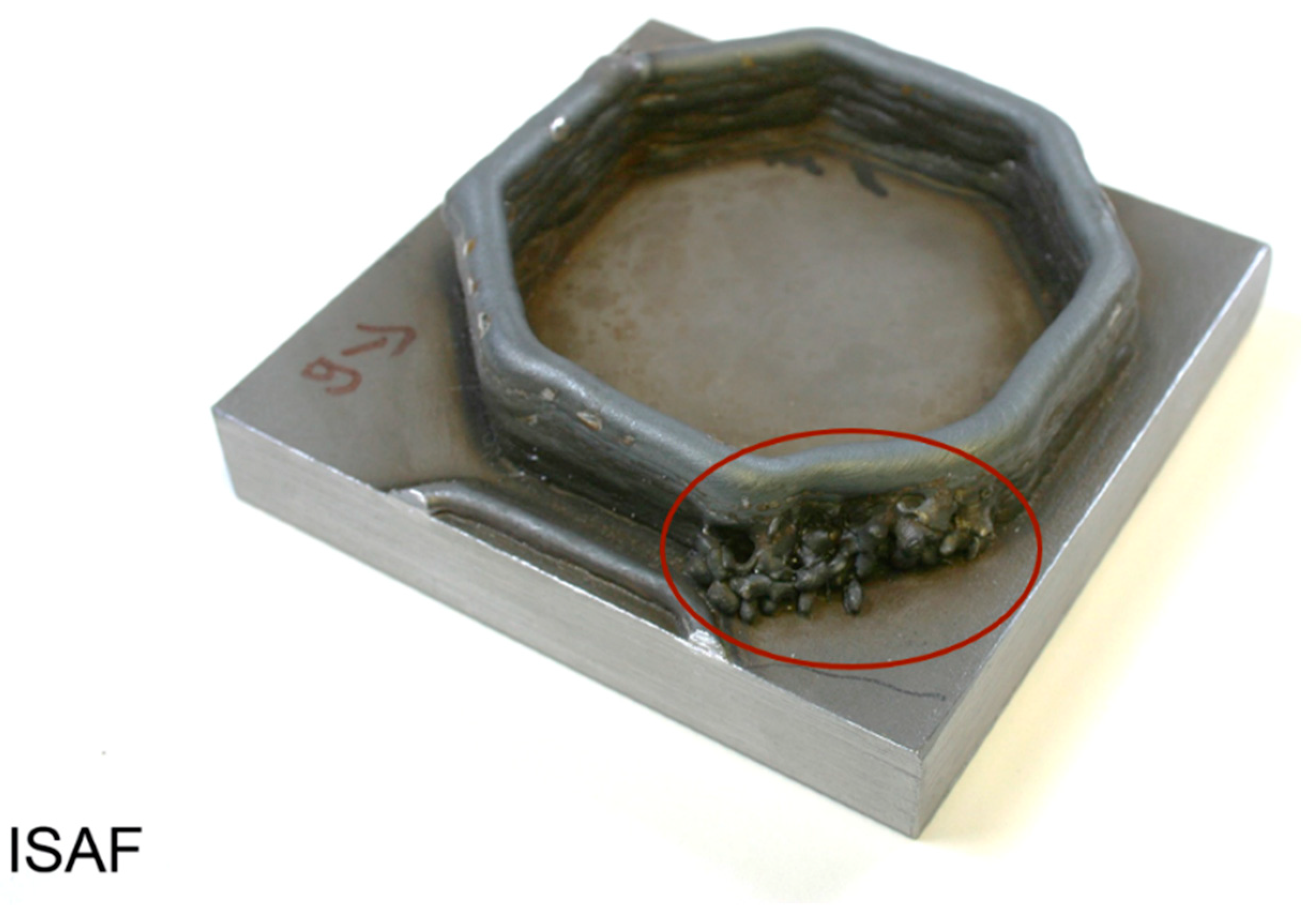
One aspect concerns the handling of the external wire feed. In addition to setting the appropriate feed angle, the directional dependency during welding must be considered. Since the arc and filler material act independently of each other, unlike in GMAW welding, for example, it is possible to obtain undesirable effects. One of these possible effects can be material leaks on or next to the welded part, as shown in
Figure 3. Another undesirable effect would be the irregular melting of the additional material.
Material leaks occur because the completely or partially melted filler material is conveyed past the arc. The reason for this is that the wire is not fed centrically into the arc. Droplet formation is delayed due to the lower energy input, and consequently, the material exits at a different point. This can be the result of changes in the welding direction or incorrect handling. The effect is particularly undesirable because, on the one hand, there is no uniform buildup rate and thus, varying component heights can be produced, and additional reworking can be necessary. It is possible to prevent this by determining the critical angles and then adapting the corresponding buildup strategy. Alternatively, a reduction in undesirable material losses can be achieved by limiting the possible angles. For this purpose, a rotatable holding unit for different substrate plates was integrated into the system concept.
Another aspect concerns the handling of fluids and sensors in the running process. The important fluids and sensors are fed through the rotating unit and the oxygen sensor, respectively, which measures a residual oxygen content of 30–50 ppm when using the alloy Ti6Al4V, through the upper end of the chamber [
19]. This should ensure that no negative influence on the corresponding components can occur due to direct contact with the weld metal. Consequently, it is thus not necessary to provide an additional safety limitation of the working chamber.
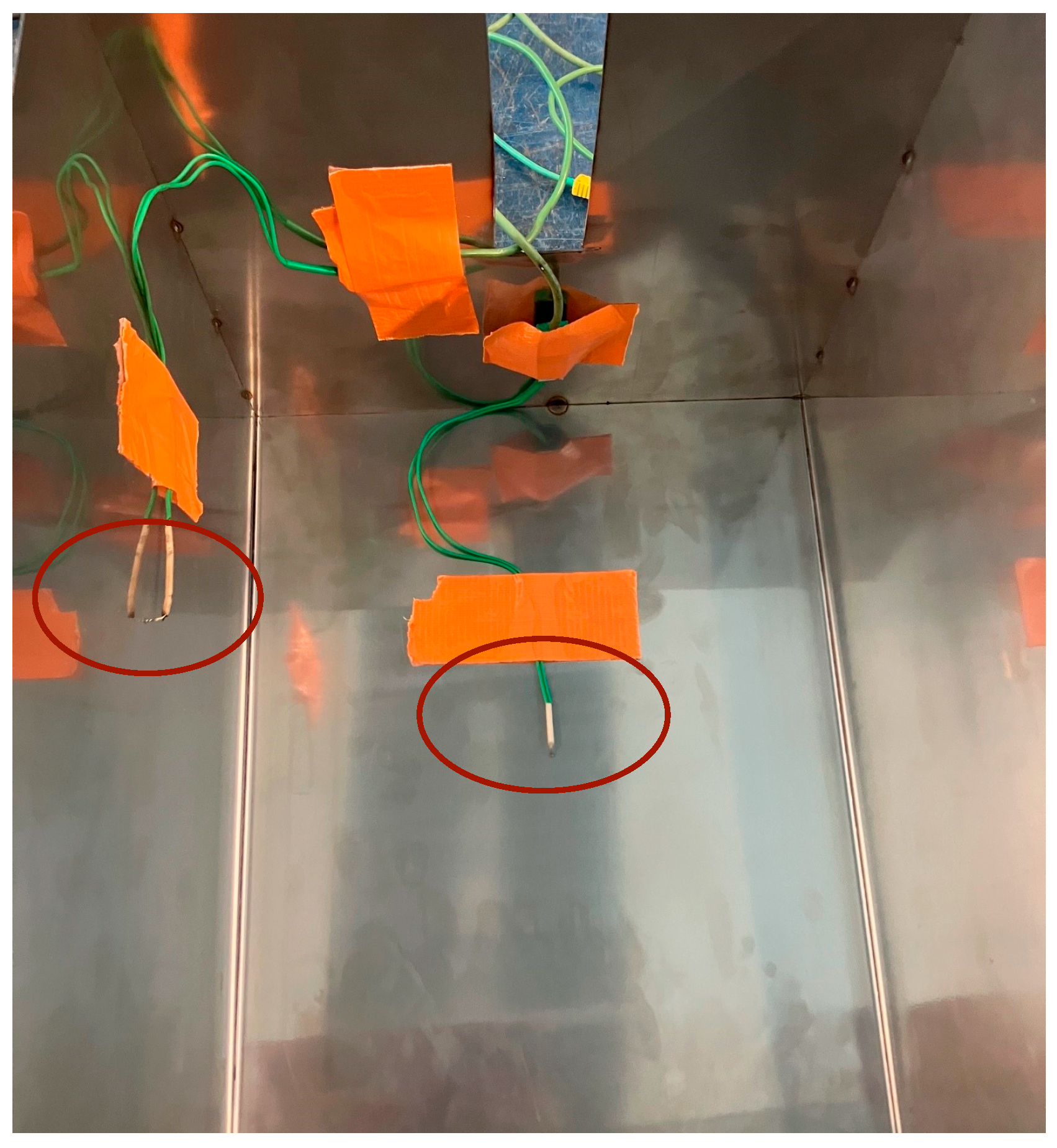
To consider the effects of the closed chamber on the temperature development of various components, further experiments were conducted. Among other aspects, these tests are intended to determine the suitability of the pre-selected components and test them for this explicit application. Various factors were to be considered, using a closed welding box with dimensions of 300 × 400 × 300 mm and a gas-cooled welding torch: the identification and evaluation of possible influencing factors, the temperature development over time, and the possible influence of further temperatures. In addition, the influence of a cooling system attached to the underside of the substrate plate and probable influences on the welding torch were considered. For this purpose, various sensors were attached to the welding box.
Figure 4 shows the sensors for measuring the temperature on the side and lid of the box.
Figure 5 shows the sensors for measuring the temperature on the substrate plate and the torch housing. In addition, the flow rate of the cooling water, as well as the temperature of the supply and return flow and the current intensity, were determined.
When determining the variables for the measurements, the fixed parameters were the duty cycle DC of 60% at 200 A, a fixed flow rate cooling water of 10 L/min, and only the supply of inert gas by welding torch. The variated parameters concern the welding current, the burning time of the arc, and the use of the cooling system. Also, a criterion for the termination of a measurement was set. When the maximum temperature of 75 °C of the welding torch casing was reached, the measurement was stopped to prevent damage to the material of the welding torch casing due to excessively high temperatures.
The first series of measurements was performed with permanent use of the cooling system. The measurement results are shown in
Table 1.
In this connection, the maximum temperature of 75 °C of the welding torch housing was reached at V2 and V3, as can be seen from the shortened test duration. As expected, the maximum temperature of the substrate plate increased with increasing welding current, as did the temperatures at the torch housing. The lower temperature rise of the torch housing at V3 is due to the shorter burning time of the arc.
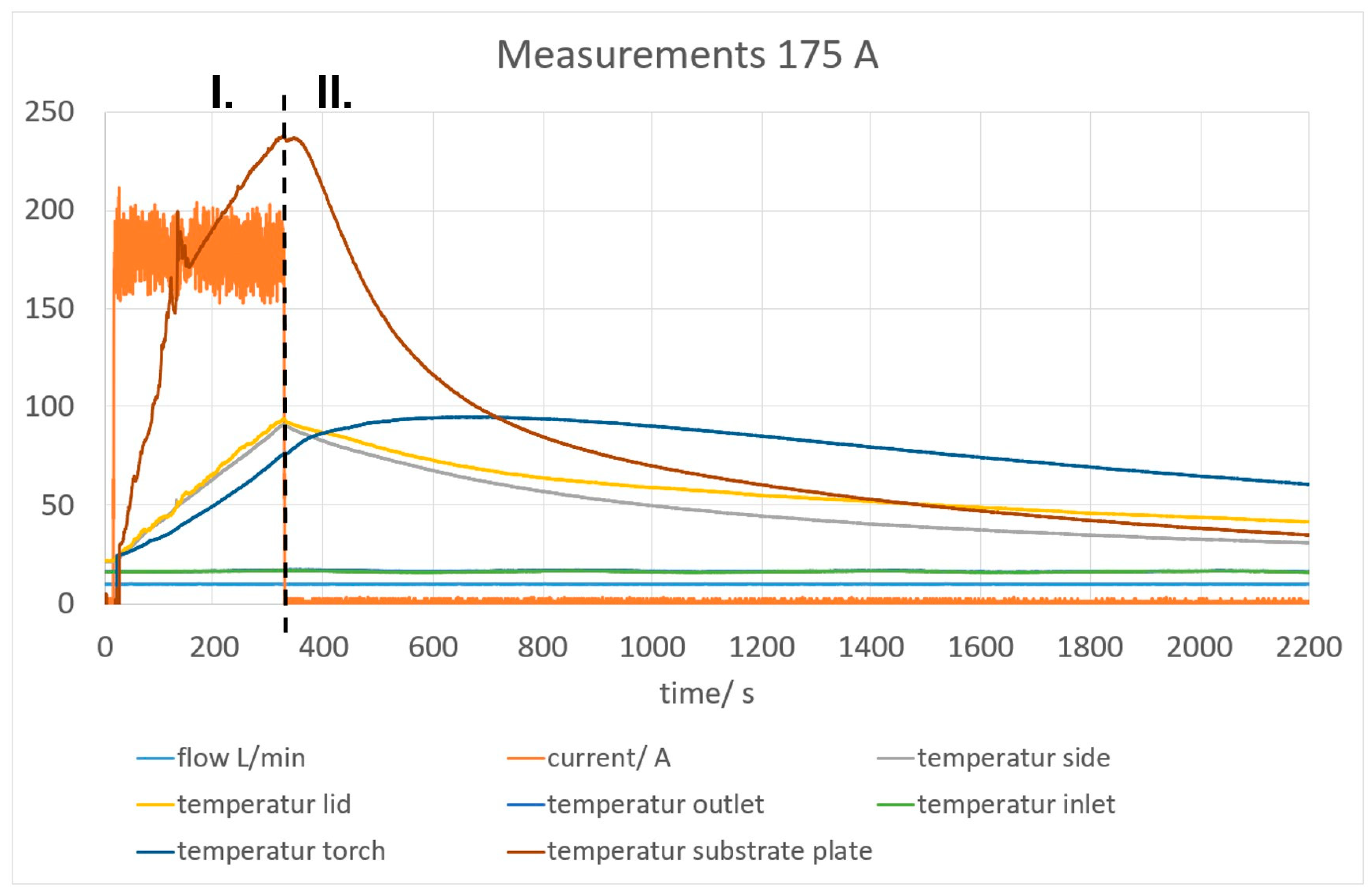
To be able to view the development of the temperature over the test period, the measured data are shown graphically in
Figure 6.
The diagram is divided into two sections: range I represents the period during which the arc is burning, and range II represents the period during which the components should cool down.
In range I, a continuous heating of all components can be seen, but above all, a rapid temperature increase of the substrate plate to just under 240 °C. This can be explained by the energy introduced by the arc. Although this temperature is not critical, since in the subsequent manufacturing process, the heat energy must be dissipated from both the substrate plate and the resulting component, the use of a cooling system is essential to reduce possible waiting times and thus prolong process times.
After switching off the arc, continuous cooling of the substrate plate, as well as the side walls and lid of the box, occurred in range II. Beyond this, however, further heating of the welding torch housing to almost 100 °C can be observed. This can be explained by the heating of the tungsten electrode inside the welding torch and subsequent heat dissipation after the arc is switched off. Consequently, the gas-cooled welding torch must be replaced by a welding torch with more efficient cooling, in this case, water cooling. This is intended to reduce the damage due to overheating on the one hand and, on the other hand, to extend the process time due to additional cooling pauses.
The second series of measurements is carried out without using the cooling system. The corresponding measurement results are listed in
Table 2.
During V5, the maximum temperature of the welding torch housing of 75 °C was also reached; consequently, the test was terminated after 4:45 min. In order to be able to better classify the temperature curves over the test time, reference is again made to the graphically prepared data from
Figure 7.
Like in
Figure 6, the ranges are divided into range I with energy input by the arc and range II the cooling process. As in the previous series of tests using water cooling, continuous heating of all components can be observed in range I. The cooling process in range II shows a significantly slower temperature drop of the components. The cooling process in
Section 2 shows a significantly slower temperature drop of the components. The heating of the burner housing due to the heat dissipation of the tungsten electrode still takes place.
In summary, a temperature increase in the welding torch can cause damage and negatively affect the process. Therefore, it is obvious to switch to the use of a water-cooled torch and increase the cooling water run-on time to further reduce the temperature in the system. It has also been shown that water cooling of the substrate plate is necessary. This contributes to removing the excess energy from the system. This allows a reduction in wait times in the process, allowing longer process times to be achieved and protecting the other components of the welding system from overheating. However, the extent to which a possible cooling effect occurs due to the permanent exchange of the shielding gas in the chamber was not investigated in the tests carried out and must be considered in later examinations.
4. Achievable Material Properties
In the following, possible achievable material properties are presented based on two exemplary components made of the materials G3Si1 and Ti6Al4V. For this purpose, a corresponding component was generatively manufactured according to the parameters listed in
Table 3. It is important to emphasize that Argon 4.6 was used as an inert gas in the additive manufacturing of both components. The aim here, particularly regarding the titanium alloy, was to check whether it is also possible to manufacture with Argon 4.8 instead of the commonly used argon.
According to the current state of the art, an alternating welding direction is useful for a uniform layer buildup without possible height differences, even for simple geometries [
20].
The buildup strategy used for both components with a length of 130 mm in
Figure 8 deviates from this. The reason for this is to avoid possible undesirable effects, for example, due to changes in direction when changing the starting point, and to create consistent conditions for each welding test.
Although the alternative buildup strategy was used, no unusual variations in the component height were observed.
The generatively manufactured components described below were welded considering a maximum intermediate layer temperature of 350 °C for steel and a maximum of 250 °C for Ti6Al4V.
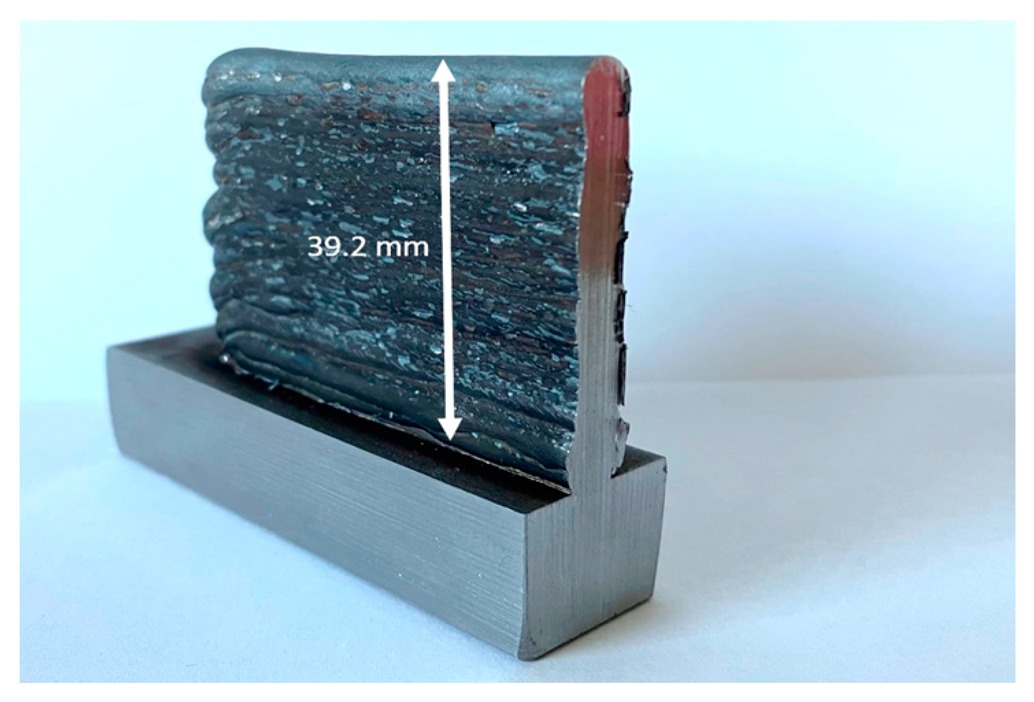
Figure 9 shows an example of the component made of G3Si1. This requires a total of 35 layers of G3Si1 wire with a diameter of 1.0 mm to achieve the component height of 39.2 mm. In
Figure 10, the component made of a titanium alloy Ti6Al4V is shown, which is also described below. To produce a component height of 22.2 mm, 15 layers are required, using a wire with a diameter of 1.0 mm.
Explicit attention was taken to ensure that the samples used did not leak material and that there were no visual abnormalities. For the Ti6Al4V component in particular, care was taken to ensure that there were no unacceptable tarnish colors, indicating oxidation.
To be able to draw conclusions from the process parameters on the effect of the corresponding component properties, the relevant investigations are described below. In addition to various micrographs, the influence of the manufacturing process on the hardness of the component was also investigated.
4.1. Metallographic Examinations G3Si1
As part of the metallographic examinations, different micrographs of the G3Si1 component manufactured using the TIG hot wire process were produced. These are shown in
Figure 11. For the last welded layers, which are in the edge region at the top of the specimen, the exact division of the layers cannot be clearly identified. The layers in the rest of the specimen show a uniform layer structure.
The microstructure in the component under consideration is uniform, and no inclusions or pores are discernible. The microstructure in the uppermost layers shows a coarser grained, partially ferritic microstructure, which can be seen in
Figure 11a,b. A finer grained, predominantly ferritic microstructure extends from the middle and lower portions of the specimen, which can be seen in detail in
Figure 11c,d. The formation of the finer-grained microstructure can be explained by the manufacturing process. This finer-grained texture of the microstructure can be explained by the smaller melt pool used in the TIG welding tests [
21]. The continuous and layer-by-layer application of the material and the associated multiple heat treatment of the already manufactured layers leads to grain refinement in the component [
22] (p. 93).
4.2. Hardness G3Si1
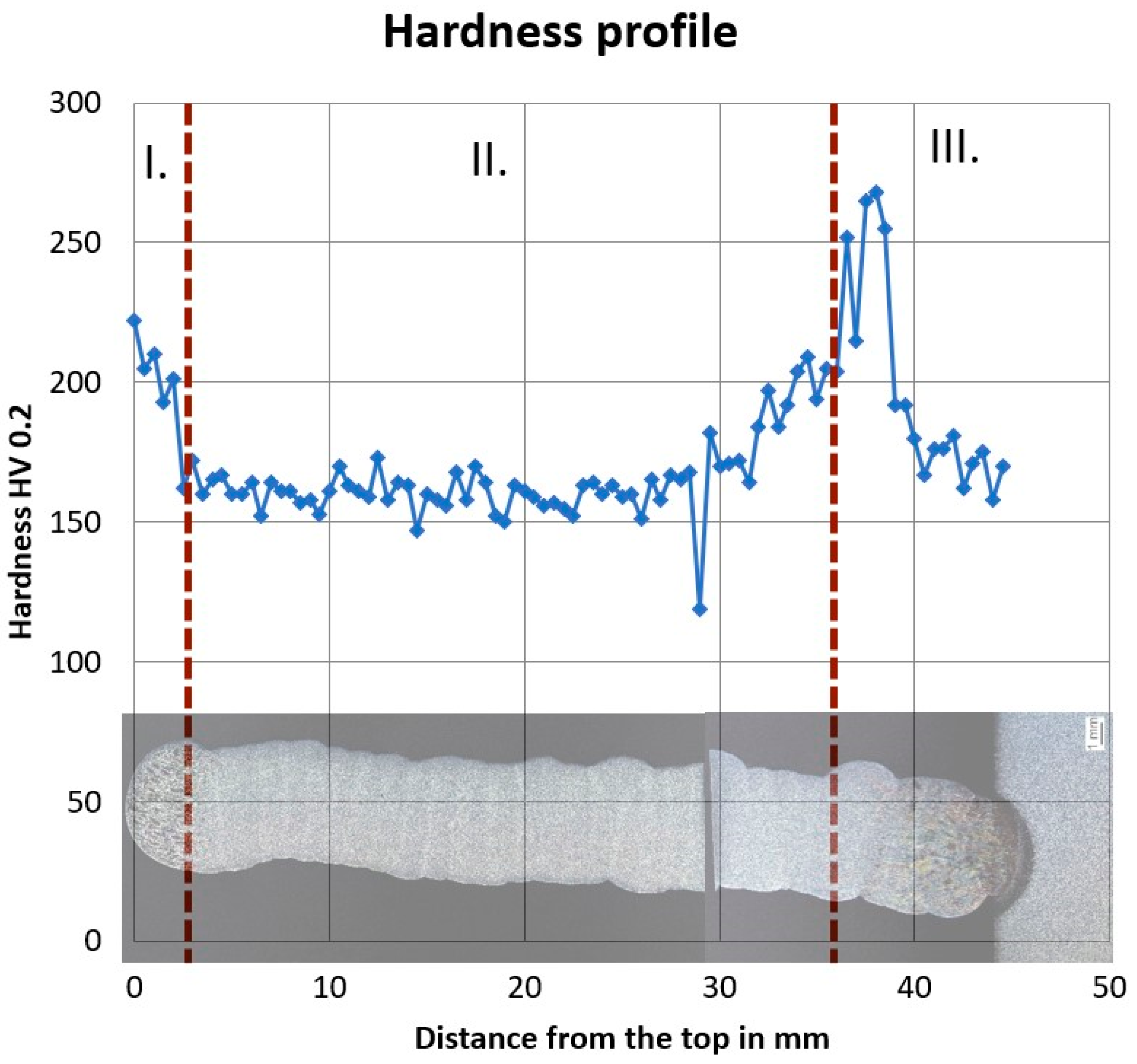
Furthermore, hardness measurements will be used to further describe the properties of the welded G3Si1 component. The values shown in
Figure 12 were determined using the Vickers method. They show the hardness progression from the upper component edge to the transition into the base material. The hardness varies mainly in the range 150–200 HV 0.2, increasing only in two sections up to 222 HV 0.2 or 268 HV 0.2.
In
Section 1, a higher hardness of up to 222 HV 0.2 can be seen. This can be explained by the coarser-grained microstructure in the upper-edge region of the component. The finer-grained microstructure in
Section 2 has an average hardness of about 165 HV 0.2. The peak in
Section 3 between 36 and 38 mm from the upper edge of the specimen represents the transition to the base material within the heat-affected zone. The results of the hardness measurement can be classified in the middle range [
23].
4.3. Metallographic Examinations Ti6Al4V
Micrographs were also produced for the manufactured component made of the titanium alloy as part of the metallographic investigations, as shown in
Figure 13. During the welding process, particular care was taken to ensure that the arc was only ignited when the residual oxygen content was below 50 ppm.
Analogous to the previously considered micrographs, the division of the weld layers in the upper-edge area cannot be determined exactly. In comparison, the titanium sample shows a higher proximity to the final contour and a clearly more recognizable layer distribution. This is due to the lower welding speed, as the filler material can be melted in a more targeted manner and thus applied layer by layer. A uniform layer structure in the rest of the sample is again clearly recognizable.
Figure 13b also illustrates that this Ti6Al4V component also has a uniform, fine-grained microstructure. In addition, no pores or other inclusions are recognizable.
4.4. Hardness Ti6Al4V
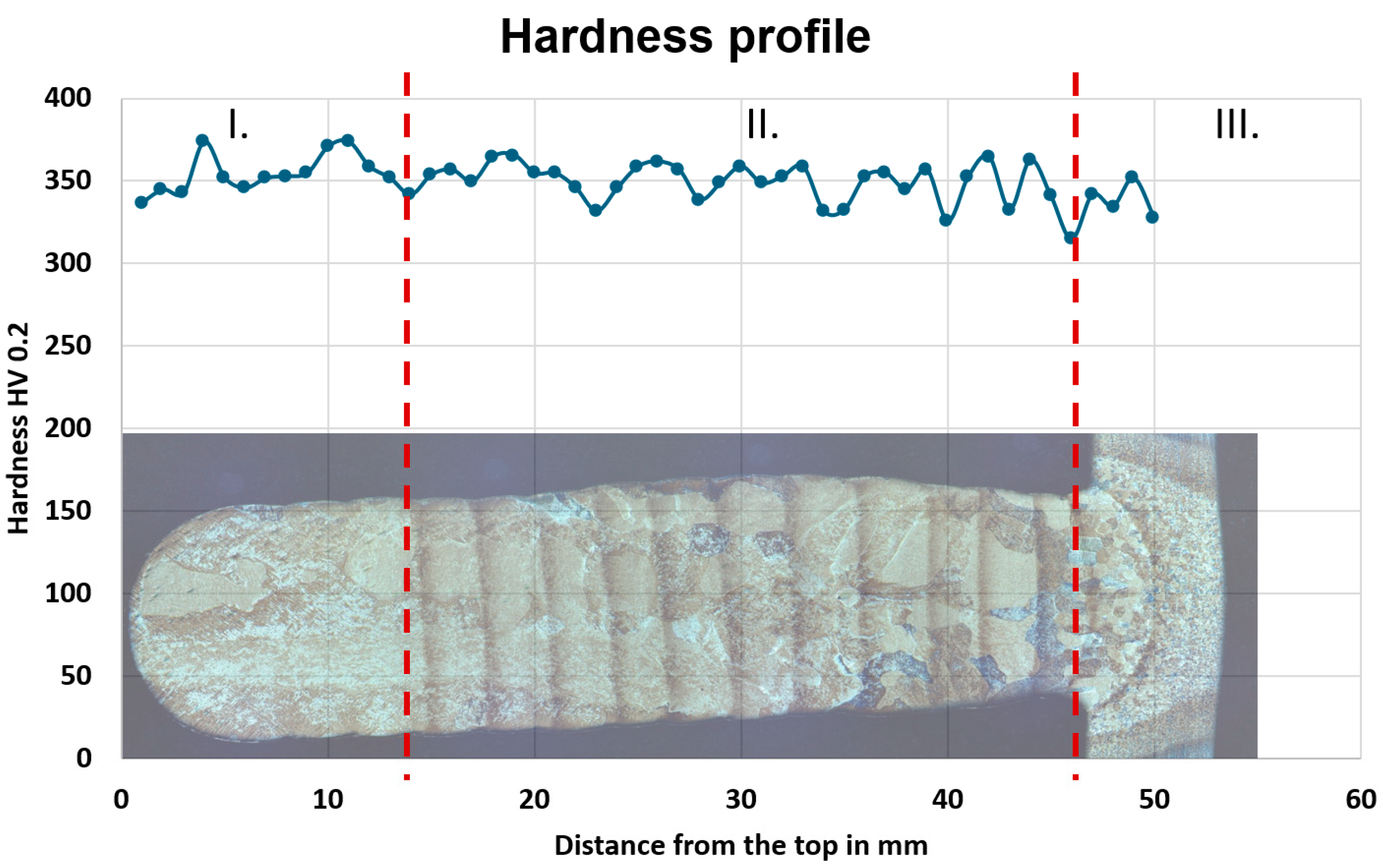
A hardness measurement was also conducted for the component made of Ti6Al4V using the Vickers method. The results are presented in
Figure 14.
The hardness curve from the upper edge of the component to the transition to the base material is again shown here. The hardness fluctuates mainly in the range of 325–365 HV 0.2. Fluctuations to a maximum of 375 HV 0.2 and a minimum of 310 HV 0.2 can also be recognized.
On average, the hardness of the exemplary component fluctuates at around 350 HV 0.2. In
Section 1, two small increases in hardness up to 375 HV 0.2 can be seen. As the fluctuations are significantly lower compared to the G3Si1 component, it can be assumed that a comparatively more uniform microstructure has been created here.
The microstructure in
Section 2 again exhibits an average hardness of around 350 HV 0.2. The slight downward trend in hardness in
Section 3 represents the transition to the base material within the heat-affected zone.
The results of the hardness measurement indicate that undesired oxidation processes of the titanium to titanium-oxide did not take place, as otherwise significantly higher hardness values above 400 HV 0.2 would have been determined.
The hardness profile of the investigated WAAM component is consequently consistent with the results from the metallographic investigations.


