Article

Creation of an Aluminum Alloy Template with a Surface Structure by Micro-Milling for Subsequent Replication of the Microstructure to Achieve Hydrophobicity

Department of Machining and Assembly, Faculty of Mechanical Engineering, Technical University of Liberec, 460 01 Liberec, Czech Republic
*
Author to whom correspondence should be addressed.
J. Manuf. Mater. Process. 2024, 8(1), 26; https://0-doi-org.brum.beds.ac.uk/10.3390/jmmp8010026
Submission received: 11 December 2023 / Revised: 22 January 2024 / Accepted: 24 January 2024 / Published: 1 February 2024

Abstract

:
This research paper focuses on the fabrication of a microstructure based on a natural structure pattern of hydrophobic properties using micro-milling technology, followed by an investigation of the dimensional accuracy, roughness, and replication of the fabricated microstructure. Design, modeling (CAD system), fabrication, and replication are the steps of this process. Knowledge of biomimetics was used to select the microstructure. The main research aim of the experiments is to verify and extend the applicability of conventional CNC manufacturing technologies to obtain a functional surface structure. The micro-milling was carried out on a conventional DMG MORI CNC machine, a CMX 600 V three-axis horizontal milling center, using an external high-frequency electric spindle clamped to the machine. The machined material was aluminum alloy EN AW 7075. The tool was a 0.1 mm diameter double-edged ball mill made of sintered carbide and coated with TiSiN. The cutting conditions were determined according to the tool manufacturer’s recommendations. To compare the achieved accuracies, the same microstructure was fabricated using PLA technology. For subsequent replication of the sample, the negative of the selected microstructure was created and machined. Subsequently, a positive microstructure was created using the silicone impression material by the replication process. This paper and the experiments performed extend the technical knowledge in the field of manufacturing surface functional structures and confirm the possibility of manufacturing the designed structures using chip and laser machining technology, with achieved discontinuities in the range of 3 to 50 μm. They also highlight the issues of replication of such structures with respect to critical manufacturing locations (geometrical parameters of the structures affecting the functional properties of the structure, venting, replica defects, etc.).

1. Introduction

The surfaces of plant and animal objects have been intensively studied in the last decades, as they provide several interesting insights and ideas that can eventually be translated into engineering practice. There are a large number of specific structures on the plant surface that provide plants with protection against water wetting and protection against excessive solar radiation or, on the contrary, improved water uptake and increased absorption of solar radiation [1,2,3,4].
Similarly, the surface of animal objects has specific structures that protect them and make it easier for them to exist in given climatic conditions. A characteristic feature of all-natural structures is their chemical composition and size. On the surface of plants, there are wax-based structures, which are often also silica-based. The surfaces of animal objects are largely equipped with protein-based structures—hairs, scrubs, scales, and others [1,2,3,5].
The common features are hierarchical structuring, the interconnection of organic and inorganic phases, and the possibility of self-repair and re-modeling. The functional structures that nature creates are usually very small, at micrometer to submicrometer levels. Replicating such structural formations with their specific properties is relatively difficult [6,7,8].
Among the earliest techniques/technologies that were able to replicate surface structures were surface replication techniques using two-stage imprinting. The natural surface serves as a pattern on which a layer of silicone is applied. After the silicone is removed from the natural surface, a mold called the first or negative replica is created and used to prepare a second, called the positive replica, which is a copy of the natural surface. This technique gives very good results at the level of copying micrometer and nanometer surface structures. The replication process can achieve very good results over a relatively small area, usually a few square centimeters. The advantage of this technique is the possibility of achieving the formation of very fine structures. Another very challenging but precise technique to obtain fine-structured surfaces is the FIB method [9,10].
Given the current interest in the use of surfaces of this type with characteristic properties, such as non-wetting or low reflectivity, it is essential that the technology to create these structures is available and can form larger areas. Such techniques currently include laser machining and chip micromachining, specifically micro-milling [11,12].
The demand for miniaturized products and devices continues to grow, and the production of miniature products and microproducts, ranging in size from a few tens of nanometers to a few millimeters, is increasingly in demand. Due to the increased demand for this technology, there are more and more cases where individual manufacturing companies are using the available equipment for the possibility of applying micro-milling using conventional CNC machines instead of special single-purpose machines. Micro-milling is one of the most reliable micromanufacturing solutions, achieving high machined surface integrity and dimensional or geometric accuracy. Using multi-axis control, complex contours can be machined with excellent continuity of different pattern structures. Technological stability and relatively simple process control principles allow the use of micro-milling in the fields of medicine (production of chips for insulin pumps, various parts of implants, and dentistry), electrical engineering, and watchmaking [13,14,15,16,17,18,19,20,21,22,23,24,25].
This article extends the knowledge of micromachining technology and the creation of functional natural microstructures using micro-milling. It then examines the dimensional and shape accuracies achieved compared with 3D fabrication data and a popular technology for fabricating surface structures—pulsed laser ablation (PLA) [26].

2. Materials and Methods

The machined material of the 30 × 20 × 10 mm specimen was aluminum alloy EN AW 7075, and this alloy was chosen because of its excellent machinability, short chip formation, good availability, frequent occurrence in machining experiments, and recommendations in scientific publications [14,15]. EN AW 7075 alloy is hardenable, characterized by high strength Rm = 360 up to 540 MPa, hardness of 104 to 160 HBW, and very good polishability [14,15].
The machining tool was chosen to get as close as possible to the replicated natural morphology in terms of shape and dimension. According to the availability and the manufacturer’s recommendations, a double-edged ball cutter with a diameter of 0.1 mm, a cutting edge radius of 0.05 mm, and a functional cutting length of 0.2 mm was selected. A preview of the basic parameters of the ball milling cutter is shown in Figure 1 and Table 1, and a detail of the tool is shown in Figure 2.
Milling was carried out on a 3-axis DMG MORI CMX 600 milling center (DMG Mori Seiki, Nagoja, Japan) with a high-speed electro spindle (Semaco, S/N 25849, Jesenik, Czech Republic) with a maximum rotation speed of 80,000 RPM using the SINUMERIK 840 D with a control system from Siemens. The instruments were clamped using an ER8 collete. The EN AW 7075 sample was fixed to the clamping device.
The electric spindle used, as seen in Figure 3, was tube-shaped and air-cooled; the tool was cooled by 16 nozzles that were arranged around the circumference of the spindle. The total weight of the additional spindle without the clamped tool was 1.6 kg. The wiring diagram of the add-on system is shown in Figure 4.
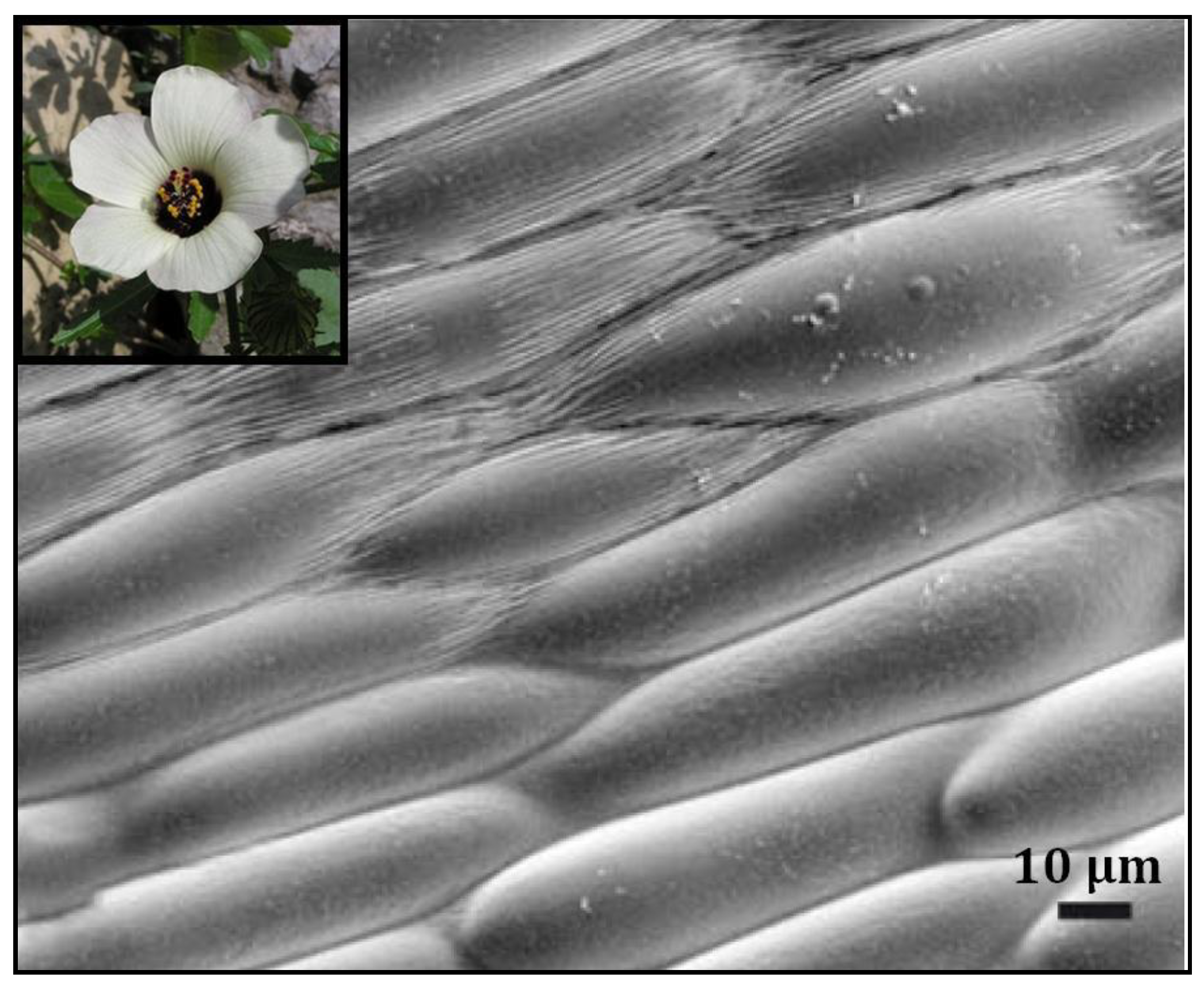
The choice of microstructure was based on information and knowledge from the science of biomimetics, which is dedicated to the study of natural objects and the subsequent imitation of their properties. A suitable microstructure for the planned experiment was inspired by the surface structure of the Hibiscus Trionum. The flower of the Hibiscus Trionum is distinguished by a surface structure that offers a surface easily cleaned by mere rain—the hydrophobic properties of the surface act as a diffraction grating. The particular shape and spacing of this cause constructive interference for different wavelengths of light in different directions, leading to angular color variation, also known as iridescence [27,28]. A detailed view of the natural structure can be seen in Figure 5.
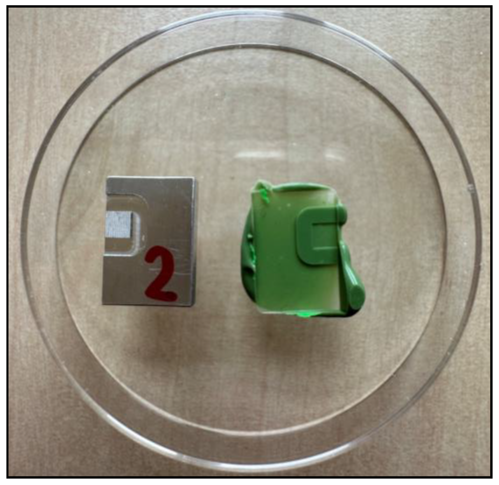
The CAD model of the microstructure of the sample was created in Autodesk Inventor Professional and then in Autodesk Fusion 360. Using the CAM software in Autodesk Fusion 360 (version 2.0.17954 x86_64), an NC program was created and transferred to the machine tool control system. Using the CAD model and the chosen parallel machining strategy, tool paths, traverse distances, safety distances, tool passes, and cutting conditions were precisely defined. For the subsequent replication of the specimens, the negative of the selected relief was first created and machined to produce a positive microstructure using the replication process [5,9,10]. The dimensions of the relief were adjusted to suit the needs of the micro-milling technology, depending on the geometry of the selected cutting tool.
The simplified theoretical profile of the microstructure of the surface of the Hibiscus Trionum flower is formed by rows of arcuate formations that have been simplified for production—creating continuous lines. The negative of the theoretical profile is represented by a field made up of elongated lamellae of triangular cross-section with a sharp apical edge. The depth of the theoretical profile was chosen to be h = 0.15 mm, the spacing of the individual elements is p = 0.2 mm, and the radius of roundness of the profile base is r = 0.075 mm; see Figure 6. The size of the machined sample was set to 3 × 3 mm due to manufacturing times and the subsequent replication process, and a detail of the 3D structure is shown in Figure 7.
The set of cutting conditions used is the number of revolutions of the electric spindle of the machine n, feed per tooth fz, feed speed vf, depth of cut ap, and width of cut ae, which are shown in Table 2. The design of the cutting conditions was based on the tool manufacturer’s recommendations.
The sample was machined using a parallel strategy. During programming, one machined element (a triangular section slat) was programmed, and then the whole structure was fabricated using the linear array tool. The calculated machine time for the fabrication of the 1 × 1 mm array was set to 25 min. The total machine time for producing a 3 × 3 mm array was 240 min. A total of 1 cutting tool was used. Details of the machining process and finished surface structure are shown in Figure 8.
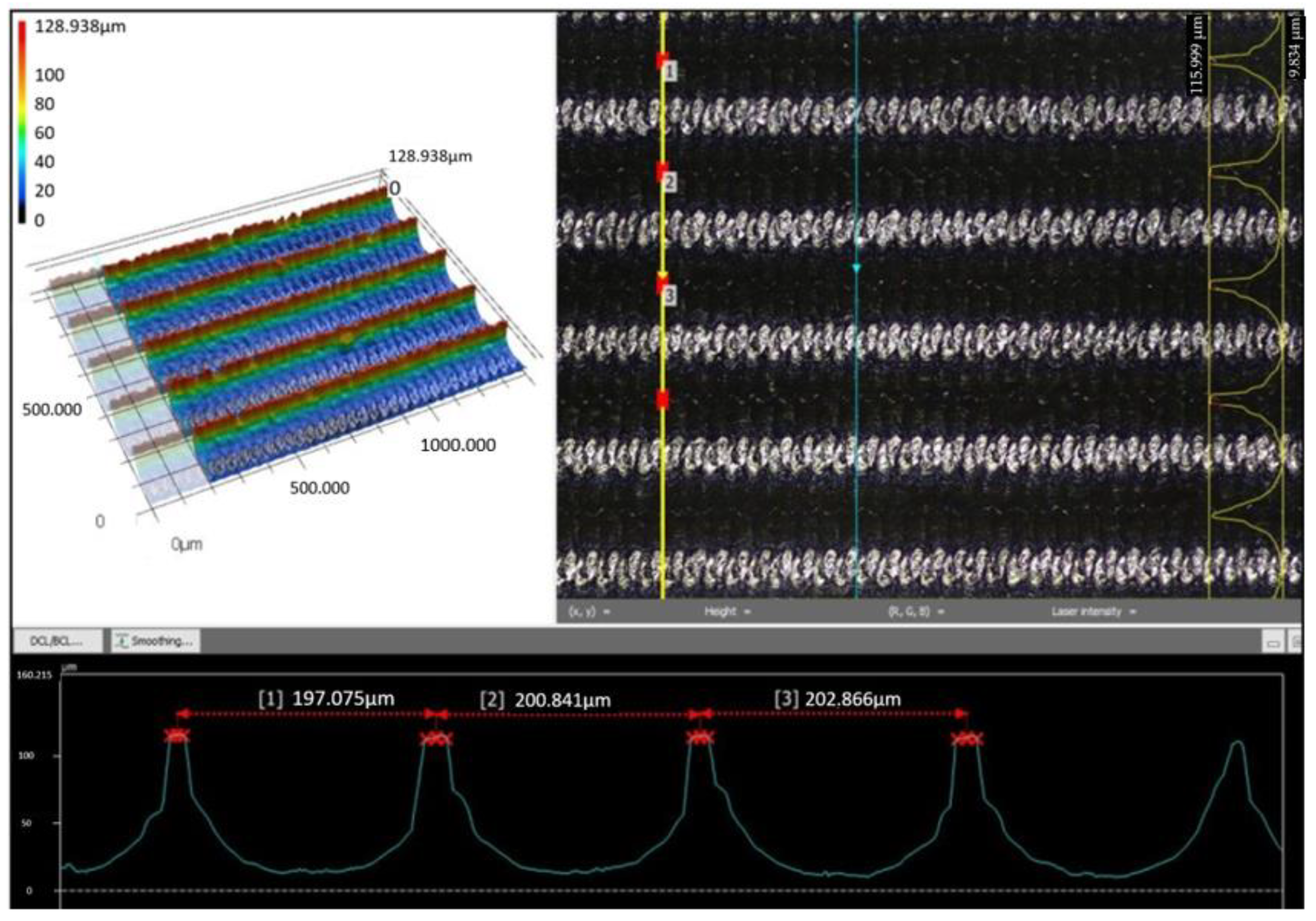
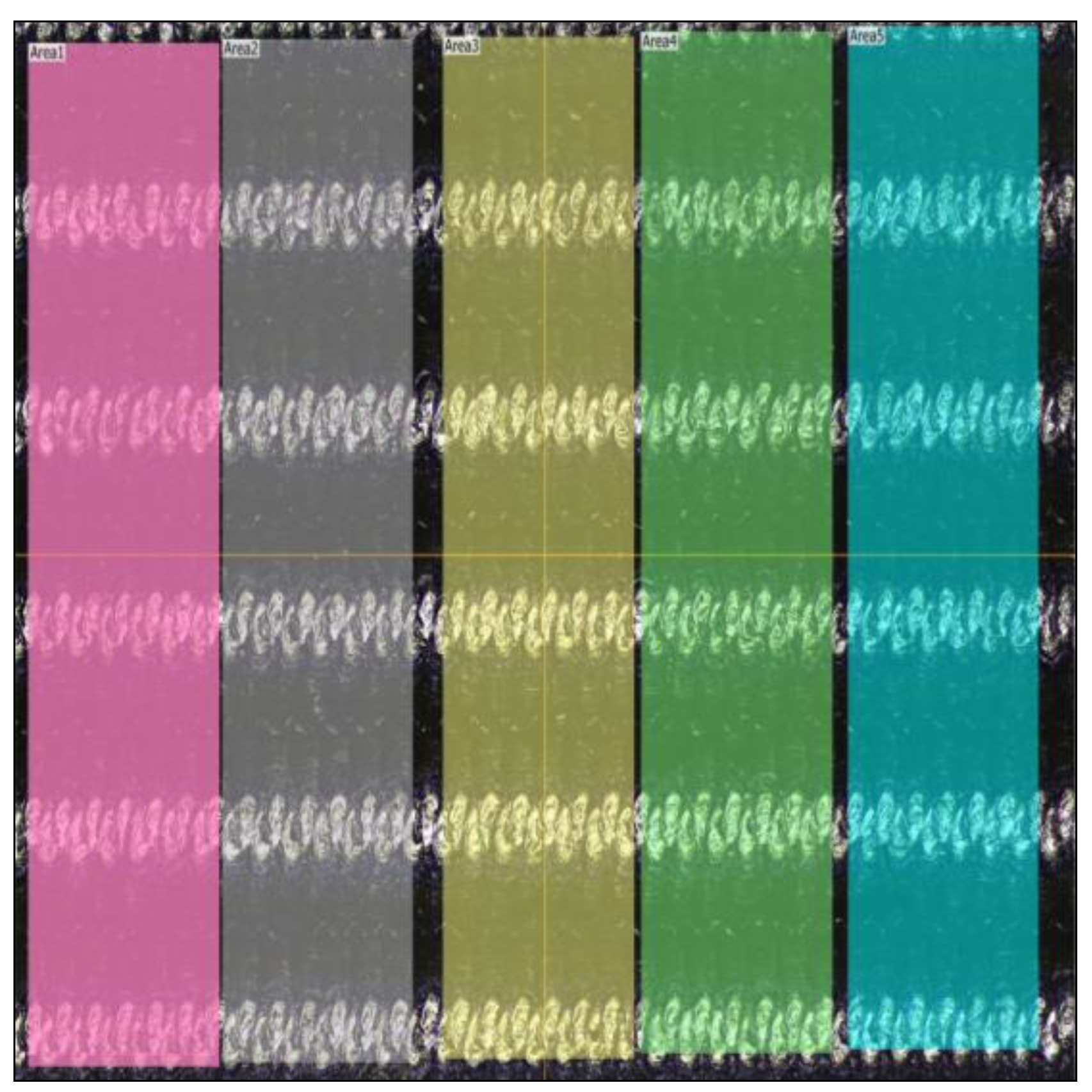
To investigate the quality achieved in the formation of the microstructure, the dimensional accuracy achieved, and the surface roughness of the microstructure formed, a non-contact measuring device, VK-X1000, from KEYENCE (Osaka, Japan), was used. This confocal microscope is equipped with a stage with driven axes and is capable of evaluating planar and profile parameters. The measured data were analyzed using the MultiFileAnalyzer software (VK-H1XMD, version 2.1.217), which was supplied by the manufacturer. A TESCAN MIRA 3 electron microscope would be used to investigate the size of burrs within the microstructure formation and also to monitor the microgeometry formed in the specimen produced by micro-milling.

3. Results

3.1. Dimensional Accuracy in Micro-Milling

To investigate the dimensional accuracy and surface roughness of the microstructure, the surface structure was scanned and measured using a confocal microscope. In Figure 9, a preview of the 3 × 3 mm grid produced and a scan of a portion of the investigated surface structure from the marked area—a yellow box—can be observed.
In terms of dimensional accuracy, two parameters were measured for the structure—the spacing of the individual elements pp and depth of machined relief hp. The spacing of the individual elements was measured in five sections, and a total of three measurements were made in each section. The number of measured areas is based on the surface structure detail under investigation; see Figure 9. The arithmetic mean of the measured values was then determined with a final value of 199.9 ± 2.4 µm. The measured values are shown in Table 3, and for a preview of the pp profile pitch measurement methodology, see Figure 10.
Profile depth measurements were taken at five selected sections, and three sites were selected in each section. The resulting calculated value of the arithmetic mean of the measured values is 100.5 ± 4.1 µm. The measured values are shown in Table 4, and a preview of the hp profile depth measurement methodology is shown in Figure 11.
It is known that the surface roughness affects the wetting properties (hydrophobicity and hydrophilicity) [10,29]; therefore, for further research, the surface roughness of Sa was measured. The measurements were carried out in five equally sized areas of 250 × 1000 µm. The resulting value of the surface roughness of Sa based on the measured values, as seen in Table 5, is 22.9 ± 1.6 µm. No λ correction factors were applied during the measurements. The measured values will serve as a starting point for the roughness achieved in other areas of research on the formation of surface structures based on biomimetic knowledge. A preview of the measured areas is shown in Figure 12.

3.2. Burr Formation in Micro-Milling

Figure 13 shows the quality of the surface structure of the selected profile produced by micro-milling technology under the selected cutting conditions and cutting tool. In Figure 13, on the left, the remaining machined chips can be observed, which remained in the structure and were carefully mechanically removed under the microscope for subsequent replication. The cavity/profile of the structure shows a minimal amount of uncut material in the form of burrs with visible tool movement paths along the length of the structure; see Figure 13 right. The profile of the structure is not completely smooth, and protrusions up to 2 µm in size can be observed between the tool paths, related to the issue of minimum depth of penetration and material being compressed under the cutting edge of the tool instead of cutting the material. However, for this experiment, this is not a negative effect. On the contrary, grooves, valleys, and burrs can, in some cases, have a positive effect on the resulting surface structure due to the increase in the specific surface area of the polymer surface and consequently increase the hydrophobicity of the structure [5,9,10]. On the upper edge of the profile, burrs can be observed instead of a rounded edge with the size of the rounding according to the radius of the cutting edge. The orientation of the resulting burrs respects the tool path according to the chosen parallel machining strategy. The occurrence of these burrs is closely related to the rigidity and possible clearance of the machine axis and thus the failure to comply with the cutting conditions at the points where the minimum amount of material occurs (profile tip). The influence of variable cutting conditions, geometry, and tool wear conditions on the microstructure formed was not investigated. A TESCAN MIRA 3 electron microscope was used to investigate the size of burrs during microstructure production and to monitor the microgeometry produced.

3.3. Created Relief Compared with the CAD Model

Measurements of the micro-dimensions of the fabricated microstructure compared with the CAD model were carried out according to the conditions described in the above chapters. The size of the investigated area was 1050 × 1400 µm. The parameters investigated for the comparison of the fabricated structure and the 3D manufacturing data were the spacing of the individual elements pp and depth of machined relief hp. Parameter measurements were carried out in several areas, and the measured parameter values pp and hp and the mean value with a statistical confidence interval of the measurement were calculated. Table 6 summarizes the achieved accuracies for the machined sample compared with the production CAD model. A significant difference can be observed for the profile depth parameter, where a 33% difference in the achieved dimensions is evident. The possible cause is the low strength of the profile in the upper sharp part. With regular tool passes, there was a gradual material removal and transformation of the machined geometry into burr form. The profile pitch parameter shows a minimum deviation from production data of 0.1%.
An important aspect in the replication of biomimetic surface structures is to look at the overall integrity of the surface formed by micro-milling, which acts as a “casting mould”. The resulting dimensional accuracy (pp, hp) and surface quality (Sa, size and occurrence of burrs, etc.) significantly influence the further development of the fabrication of the final replica of a given structure [5,9,10], especially when semi-crystalline polymer materials are used.

3.4. Created Relief by Micro-Milling Compared to the PLA Method

As part of the comparative measurement, a microstructured surface sample was fabricated using a USP laser device using PLA technology. The USP laser is an ultrashort pulsed laser characterized by the emission of ultrashort pulses of light, in the order of femtoseconds to picoseconds. They are used for micromachining because of the minimal thermal effect on the material being machined, unlike the continuous laser. For laser micromachining, the technological conditions were set according to Table 7 [26].
To check the dimensional accuracy achieved, the same measurement methodology as in Section 3.1 was used with the same monitored parameters. A preview of the surface scan is shown in Figure 14, and a comparison of the achieved accuracies with the production data is shown in Table 8.

3.5. Replication

For the machined sample with the fabricated microstructure, the replication of the surface structure was performed according to [9]. The replication obtained a structure that should be analogous to the simplified structure of the Ibis Trionum. The resulting machined surface was completely replicated three times; see Figure 15 for a preview of the machined sample and its replica.
Two parameters were measured on the selected replicas—the spacing of individual profile elements pp and depth of the replicated profile hp. The number of measurements was the same as for the machined sample. The measured and calculated values are shown in Table 9 and Table 10. The overall comparison with the production CAD data is shown in Table 11.
Figure 16 shows SEM images showing that the replica perfectly reproduces the machined surface of the specimen, including visible tool paths and protrusions up to 2 µm in size.

4. Discussion

This paper was focused on the formation of natural surface microstructures with hydrophobic properties using micro-milling technology. To produce the desired microstructure, it was necessary to first design the microstructure, model it, fabricate it using micro-milling technology, and then replicate the structure. The choice of the microstructure was based on the knowledge of the scientific field of biomimetics, which is dedicated to the study of natural objects and the subsequent replication of their properties. A suitable microstructure for the planned experiment was inspired by the surface structure of the three-part hibiscus flower, which is notable for its hydrophobic structure, among other things. The machined material was aluminum alloy EN AW 7075. The tool was a double-edged ball mill with a diameter of 0.1 mm made of sintered carbide and coated with TiSiN. The cutting conditions were determined according to the tool manufacturer’s recommendations. For the subsequent replication of the specimen, a negative of the selected microstructure was created and machined, from which a positive microstructure was created by the replication process using a silicone impression compound to transfer the maximum amount of detail occurring on the surface of the machined structure.
The following findings can be summarized from the obtained results:
  • It was possible to produce the microstructure with a selected set of parameters (material to be machined, cutting tool, cutting conditions, dimensions of the structure).
  • The structures inspired by the natural microstructure were created by micro-milling at a scale of 200 µm and achieved a dimensional accuracy of almost 70% for the profile depth parameter and almost 100% for the profile pitch parameter compared to the CAD master.
  • The replicated microstructure matched the production data 51% for the profile depth and nearly 100% for the observed profile pitch parameter.
  • The microstructure created by micro-milling compared to the microstructure created by the PLA method showed different accuracies for the observed parameters. A significant difference can be observed for the parameter pp.
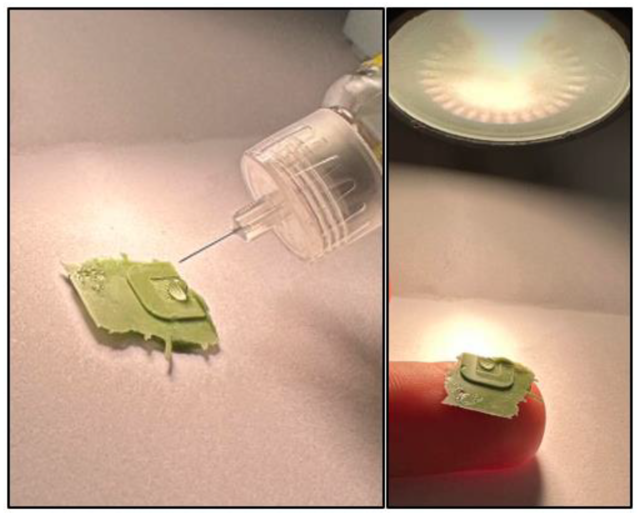
  • It was further shown that the transferred relief dimensions did not change after multiple replications, and the replicated sample showed signs of hydrophobicity; see Figure 17.
The quality of the transferred micro-dimensions between the CAD model, the microstructure created by micro-milling, the microstructure created by laser technology, and the resulting replication is summarized in Table 12.

5. Conclusions

The present paper contributes to expanding the knowledge of the technological process of micro-milling and the fabrication of nature-inspired microstructures. This paper focused on the creation of a surface microstructure based on a template with hydrophobic properties, fabricated by micro-milling. For subsequent replication of the specimen, a negative of the chosen microstructure was created and machined, from which a positive microstructure was created through the replication process.
To produce the desired microstructure, it was necessary to first design the microstructure, model it, fabricate it with micro-milling technology, and then replicate the structure. This whole process is the subject of the paper. The research also included a comparison of the microstructure created by micro-milling with the same microstructure created by the PLA method.
From the extensive set of measurements and results obtained by micro-milling, the following can be formulated:
  • It is verified that the proposed natural microstructure can be produced by micro-milling. The resulting dimensional and shape accuracy of the structure is significantly related to the designed profile geometry or the mechanical strength of the profile (formation of burrs, elastic, and plastic deformations).
  • The microstructure created by micro-milling achieved a dimensional accuracy of almost 100% for the observed profile pitch parameter compared to the CAD master. The profile depth parameter of the structure will be significantly affected by the designed profile geometry. The difference between the production data and the fabricated structure concerning the observed profile depth parameter was 33% (approximately 50 μm).
  • The manufacturability of the designed structure was further verified using PLA technology. During the metrological control, a maximum deviation from the fabrication data of 2% (approximately 3 μm) was measured and found. The fabrication progress of the designed structure was significantly influenced by the choice of appropriate process conditions with suitable production times, geometric and dimensional accuracy, and surface quality. In the case of the fabrication of surface structures on planar surfaces, PLA technology appears to be a more accurate and faster technology. Significant limiting elements for the use of this technology are the application on general surfaces and the cost.
  • The microstructures produced can be replicated using a replication process. The replica using silicone impression material then faithfully matches the surface of the machined microstructure, even when the process is repeated several times. The quality of the achieved results is significantly influenced by the nature of the produced structure (geometric proportions, mechanical load-bearing capacity of the profile), the flow of the impression mass into the structure (venting of the structure, elimination of air pockets, open channels), and the choice of suitable impression material (formation of hierarchical structures, amount of transferred details).
  • Further research aims to modify the geometric parameters of the above structure using micro-milling in an attempt to obtain deviations from the production data in the order of percentages and to produce with subsequent replication other natural structures with functional properties (hydrophobicity, hydrophilicity, and others).

Author Contributions

Conceptualization, A.K. and Š.D.; methodology, A.K., Š.D. and M.V.; validation, Š.D.; formal analysis, Š.D.; investigation, A.K. and M.V.; resources, A.K. and M.V.; data curation, M.V.; writing—original draft preparation, A.K.; writing—review and editing, A.K.; visualization, A.K.; supervision, Š.D.; project administration, A.K. All authors have read and agreed to the published version of the manuscript.

Funding

Research was funded by institutional funding of science and research at the Technical University of Liberec and by the Student Grant Competition of the Technical University of Liberec under project No. SGS-2023-5387 “Research in the field of micromachining—micro milling”.

Data Availability Statement

The authors confirm that the data supporting the findings of this study are available within the article.

Conflicts of Interest

The authors declare no conflicts of interest. The funders had no role in the design of the study; in the collection, analyses, or interpretation of data; in the writing of the manuscript; or in the decision to publish the results.

References

  1. Huang, Z.; Cai, C.; Kuai, L.; Li, T.; Huttula, M.; Cao, W. Leaf-Structure Patterning for Antireflective and Self-Cleaning Surfaces on Si-Based Solar Cells.Solar. Energy 2018, 159, 733–741. [Google Scholar]
  2. Bhushan, B.; Jung, Y.C.; Koch, K. Micro-, Nano- and Hierarchical Structures for Superhydrophobicity, Self-Cleaning and Low Adhesion. Philos. Trans. R. Soc. A 2009, 367, 1631–1672. [Google Scholar] [CrossRef]
  3. Huang, Z.; Yang, S.; Zhang, H.; Zhang, M.; Cao, W. Replication of Leaf Surface Structures for Light Harvesting. Sci. Rep. 2015, 5, 14281. [Google Scholar] [CrossRef]
  4. Antonov, D.V.; Islamova, A.G.; Strizhak, P.A. Hydrophilic and Hydrophobic Surfaces: Features of Interaction with Liquid Drops. Materials 2023, 16, 5932. [Google Scholar] [CrossRef] [PubMed]
  5. Kroisová, D.; Dvořáčková, Š; Kůsa, P. Formation of Nanostructure during Replication of a Hierarchical Plant Surface. Nanomaterials 2021, 11, 2811. [Google Scholar] [CrossRef] [PubMed]
  6. Zhang, S.; Zhou, Y.; Zhang, H.; Zhang, X.; To, S. Advances in Ultra-Precision Machining of Micro-Structured Functional Surfaces and Their Typical Applications. Int. J. Mach. Tools Manuf. 2019, 142, 16–41. [Google Scholar] [CrossRef]
  7. O’Toole, L.; Kang, C.; Fang, F. Precision Micro-Milling Process: State of the Art. Adv. Manuf. 2020, 9, 173–205. [Google Scholar] [CrossRef] [PubMed]
  8. Balázs, B.Z.; Geier, N.; Takács, M.; Davim, J.P. A Review on Micro-Milling: Recent Advances and Future Trends. Int. J. Adv. Manuf. Technol. 2020, 112, 655–684. [Google Scholar] [CrossRef]
  9. Kroisová, D.; Šamořil, T.; Dvořáčková, Š. The Use of FIB for the Preparation of a Structure Analogous to the Natural Sur-Face and Its Replication by Selected Types of Polymers. Manuf. Technol. 2021, 21, 91–97. [Google Scholar] [CrossRef]
  10. Dora, K. 2022-01-29T19:07:15Z. Method of Obtaining a Nanostructured Hierarchical Surface of a Positive Imprint of a Copied Natural Surface. Available online: https://isdv.upv.cz/doc/FullFiles/Patents/FullDocuments/308/308915.pdf (accessed on 1 December 2023).
  11. Chae, J.-Y.; Park, S.S.; Freiheit, T. Investigation of Micro-Cutting Operations. Int. J. Mach. Tools Manuf. 2006, 46, 313–332. [Google Scholar] [CrossRef]
  12. Chen, N.; Li, H.N.; Wu, J.; Li, Z.; Li, L.; Liu, G.; He, N. Advances in Micro Milling: From Tool Fabrication to Process Outcomes. Int. J. Mach. Tools Manuf. 2021, 160, 103670. [Google Scholar] [CrossRef]
  13. Filiz, S.; Xie, L.; Weiss, L.E.; Özdoğanlar, O.B. Micromilling of Microbarbs for Medical Implants. Int. J. Mach. Tools Manuf. 2008, 48, 459–472. [Google Scholar] [CrossRef]
  14. Rahnama, R.; Sajjadi, M.; Park, S.S. Chatter Suppression in Micro End Milling with Process Damping. J. Mater. Process. Technol. 2009, 209, 5766–5776. [Google Scholar] [CrossRef]
  15. Park, S.S.; Malekian, M. Mechanistic Modeling and Accurate Measurement of Micro End Milling Forces. CIRP Ann. 2009, 58, 49–52. [Google Scholar] [CrossRef]
  16. Lu, X.; Cong, C.; Hou, P.; Xv, K.; Liang, S.Y. Improved Cutting Force Modelling in Micro-Milling Aluminum Alloy LF 21 Considering Tool Wear. Appl. Sci. 2022, 12, 5357. [Google Scholar] [CrossRef]
  17. Song, B.; Zhang, D.; Jing, X.; Ren, Y.; Chen, Y.; Li, H. Theoretical and Experimental Investigation of Surface Textures in Vibration-Assisted Micro Milling. Micromachines 2024, 15, 139. [Google Scholar] [CrossRef] [PubMed]
  18. Ercetin, A.; Aslantaş, K.; Özgün, Ö.; Perçin, M.; Chandrashekarappa, M.P.G. Optimization of Machining Parameters to Minimize Cutting Forces and Surface Roughness in Micro-Milling of Mg13Sn Alloy. Micromachines 2023, 14, 1590. [Google Scholar] [CrossRef]
  19. Dumitras, C.G.; Chitariu, D.F.; Chifan, F.; Lates, C.G.; Horodinca, M. Surface Quality Optimization in Micromachining with Cutting Tool Having Regular Constructive Geometry. Micromachines 2022, 13, 422. [Google Scholar] [CrossRef]
  20. Faraz, M.I.; Petru, J. Evaluation of Machining Variables on Machinability of Nickel Alloy Inconel 718 Using Coated Carbide Tools. Machines 2024, 12, 4. [Google Scholar] [CrossRef]
  21. Basile, V.; Modica, F.; Rebaioli, L.; Surace, R.; Fassi, I. Process Chains for Micro-Manufacturing: Modeling and Case Studies. J. Manuf. Mater. Process. 2023, 7, 215. [Google Scholar] [CrossRef]
  22. Soriano Gonzalez, L.; Medina Aguirre, F.; Soo, S.L.; Hood, R.; Novovic, D. Influence of Size Effect in Milling of a Single-Crystal Nickel-Based Superalloy. Micromachines 2023, 14, 313. [Google Scholar] [CrossRef]
  23. Zhang, Y.; Yuan, Z.; Fang, B.; Gao, L.; Chen, Z.; Su, G. Study on the Mechanism of Burr Formation by Simulation and Experiment in Ultrasonic Vibration-Assisted Micromilling. Micromachines 2023, 14, 625. [Google Scholar] [CrossRef] [PubMed]
  24. Liu, T.; Wang, Q.; Wang, W. Micro-Milling Tool Wear Monitoring via Nonlinear Cutting Force Model. Micromachines 2022, 13, 943. [Google Scholar] [CrossRef] [PubMed]
  25. Karakılınç, U.; Ergene, B.; Yalçın, B.; Aslantaş, K.; Erçetin, A. Comparative Analysis of Minimum Chip Thickness, Surface Quality and Burr Formation in Micro-Milling of Wrought and Selective Laser Melted Ti64. Micromachines 2023, 14, 1160. [Google Scholar] [CrossRef] [PubMed]
  26. Tomáš, P.; Novák, M.; Zeman, P.; Holešovský, F. Femtosecond Laser Processing of Advanced Technical Materials. Acta Polytech. 2023, 63, 36–49. [Google Scholar]
  27. Kourounioti, R.L.A.; Band, L.R.; Fozard, J.A.; Hampstead, A.; Lovrics, A.; Moyroud, E.; Vignolini, S.; King, J.R.; Jensen, O.E.; Glover, B.J. Buckling as an Origin of Ordered Cuticular Patterns in Flower Petals. J. R. Soc. Interface 2013, 10, 20120847. [Google Scholar] [CrossRef] [PubMed]
  28. Whitney, H.M.; Kolle, M.; Andrew, P.; Chittka, L.; Steiner, U.; Glover, B.J. Floral Iridescence, Produced by Diffractive Optics, Acts as a Cue for Animal Pollinators. Science 2009, 323, 130–133. [Google Scholar] [CrossRef]
  29. Quéré, D. Wetting and Roughness. Annu. Rev. Mater. Res. 2008, 38, 71–99. [Google Scholar] [CrossRef]
Figure 1. Main dimensions of the used micro-milling cutter.
Jmmp 08 00026 g001
Figure 2. Detailed view of the cutting part of the microtool.
Jmmp 08 00026 g002
Figure 3. Detailed view of the attachment, wiring, and clamped microtool.
Jmmp 08 00026 g003
Figure 4. Wiring diagram of the additional electro-spindle system.
Jmmp 08 00026 g004
Figure 5. The original natural structure of a Hibiscus Trionum.
Jmmp 08 00026 g005
Figure 6. Sketch with dimensions of the modified structure for production technology.
Jmmp 08 00026 g006
Figure 7. Preview of 3D manufacturing data of the surface structure.
Jmmp 08 00026 g007
Figure 8. Micro-milling process and machined sample with the microstructure.
Jmmp 08 00026 g008
Figure 9. Detail of the fabricated surface structure and 3D detail of the measured area.
Jmmp 08 00026 g009
Figure 10. Preview of structure profile pitch measurement pp.
Jmmp 08 00026 g010
Figure 11. Preview of the structure profile depth measurement hp.
Jmmp 08 00026 g011
Figure 12. Preview of the measured areas for roughness evaluation Sa.
Jmmp 08 00026 g012
Figure 13. Detailed view from the TESCAN MIRA 3 scanning raster microscope of the machined structure. Yellow box: it shows exact position of the measurement.
Jmmp 08 00026 g013
Figure 14. A 3D detail of the formed surface structure using PLA.
Jmmp 08 00026 g014
Figure 15. Machined sample with a replica.
Jmmp 08 00026 g015
Figure 16. SEM images of the replicated structure from the micro-milled sample.
Jmmp 08 00026 g016
Figure 17. Testing of the fabricated replica of the designed surface structure.
Jmmp 08 00026 g017
Table 1. Basic technical parameters of the machining tool.
Double-Edged Ball Milling Cutter 2HCB-001-002-S04
Diameter of the toolD[mm]0.1 (+0/−0.005)
Cutting edge radiusR[mm]0.05 (±0.005)
Number of cutting edges--2
Helix pitch angle-[°]30
Tool material--sintered carbide
Cutting tool grain size-[μm]0.2
Coating of the cutting part--TiSiN
Functional lengthL1[mm]0.2
Overall lengthL[mm]40
Tool shank diameterD[mm]4 h5
Tool supplier--PM TECH
Table 2. Set of cutting conditions used in the.
Cutting Conditions of Micro Milling
Revolutionsn[ot/min]60,000
Feed per toothfz[mm]0.002
Feed speedvf[mm/min]240
Depth of cutap[mm]0.004
Width of cutae[mm]0.02
Table 3. Measured values of the profile pitch parameter pp.
Profile Pitch pp [µm]
Measurement Numberpp1pp2pp3
1198.7198.8201.5
2197.1200.8202.9
3199.1198.2203.6
4201.9199.2201.1
5197.6203.2195.3
Table 4. Measured values of the structure profile depth parameter hp.
Profile Depth hp [µm]
Measurement Numberhp1hp2hp3
199.197.6101.1
2109.1106.6102.1
397.8101.6103.4
498.0101.3102.5
595.699.592.8
Table 5. Measured values of the structure profile depth parameter hp.
Surface Roughness of the Structure Sa [µm]
Measurement NumberSa
123.6 ± 1.6
222.9 ± 1.5
323.2 ± 1.6
422.4 ± 1.6
522.5 ± 1.6
Table 6. Summary of the initial parameters compared to the results obtained with micro-milling technology.
Sketch of the Basic Element of the StructureJmmp 08 00026 i001
Structure ParameterCADSample—Micro MillingSize Difference [%]
pp [µm]200199.9 ± 2.40.1
hp [µm]150100.5 ± 4.133
Table 7. Summary of initial parameters compared to the results obtained with micro-milling technology.
Technical Parameters and Cutting Conditions in Laser Micromachining
Micromachining stationsMaster 1
Laser SourceCarbide-CB3-40W
ManufacturerLight Conversion
Harmonic wavelengthsIH—1030 nm, IIH—515 nm, IIIH—343 nm
Output40 W
Pulse timeτP = 270 fs–10 ps
Repetition ratef = 200–1000 kHz
Focusing lensF-theta telecentrická
Galvo scanning headc
Pulse lengthτP = 270 [fs]
Wavelengthλ = 515 [nm]
Beam diameterd = 25 [μm]
Machining time10 [min]
Table 8. Summary of the baseline parameters compared to the results achieved with PLA technology.
Sketch of the Basic Element of the StructureJmmp 08 00026 i002
Structure ParameterCADSample—PLASize Difference [%]
pp [µm]200200.3 ± 0.32
hp [µm]150147.0 ± 1.30.2
Table 9. Measured values of the replica profile pitch parameter pp.
Profile Pitch of the Replica pp [µm]
Measurement Numberpp1pp2pp3
1200.1201.3199.9
2199.7198.9200.2
3200.7201.3199.9
4201.4200.9200.5
5200.8200.8200.1
Table 10. Measured values of the replica profile depth parameter hp.
Profile Depth hp [µm]
Measurement Numberhp1hp2hp3
176.677.376.6
276.074.878.0
377.376.676.6
475.674.275.2
575.778.577.9
Table 11. Summary of the default parameters compared to the replication results.
Sketch of the Basic Element of the StructureJmmp 08 00026 i003
Structure ParameterCADSample—ReplicaSize Difference [%]
pp [µm]200200.4 ± 0.70.2
hp [µm]15076.5 ± 1.249
Table 12. Overall overview of dimensional accuracies and production times achieved for individual samples.
Relief Type Triangular SlatsProfile Pitch [μm]Profile Depth [μm]Manufacturing Time [min]
CADJmmp 08 00026 i00420015030
MicromillingJmmp 08 00026 i005199.9 ± 2.4100.5 ± 4.1240
PLAJmmp 08 00026 i006200.3 ± 0.3147.0 ± 1.36
ReplicaJmmp 08 00026 i007200.4 ± 0.776.5 ± 1.215
Disclaimer/Publisher’s Note: The statements, opinions and data contained in all publications are solely those of the individual author(s) and contributor(s) and not of MDPI and/or the editor(s). MDPI and/or the editor(s) disclaim responsibility for any injury to people or property resulting from any ideas, methods, instructions or products referred to in the content.

