Recent Progress in the Study of Thermal Properties and Tribological Behaviors of Hexagonal Boron Nitride-Reinforced Composites


 ,
,  , and
, and 
Abstract
:1. Introduction
2. Thermal Properties
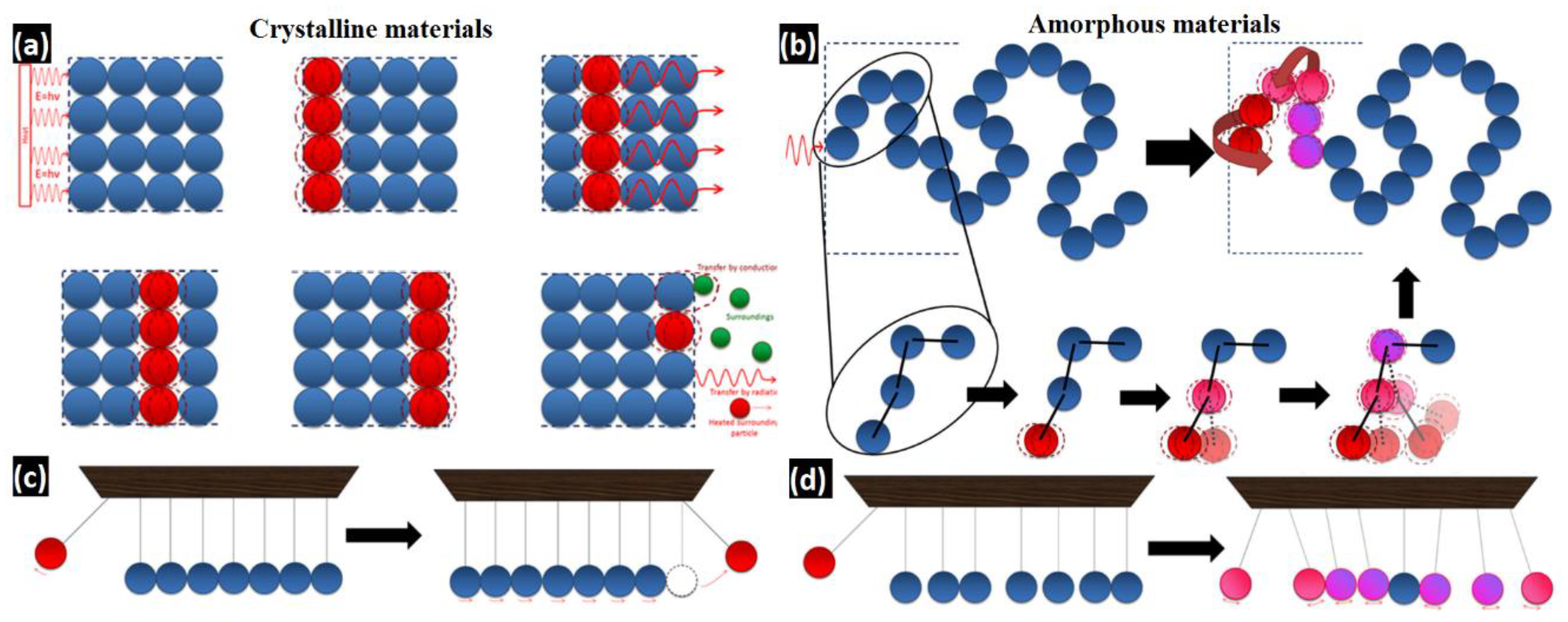
2.1. Conductivity Theory
2.2. Thermal Properties of h-BN
2.3. Fabrication of h-BN-Reinforced Polymer-Based Composites
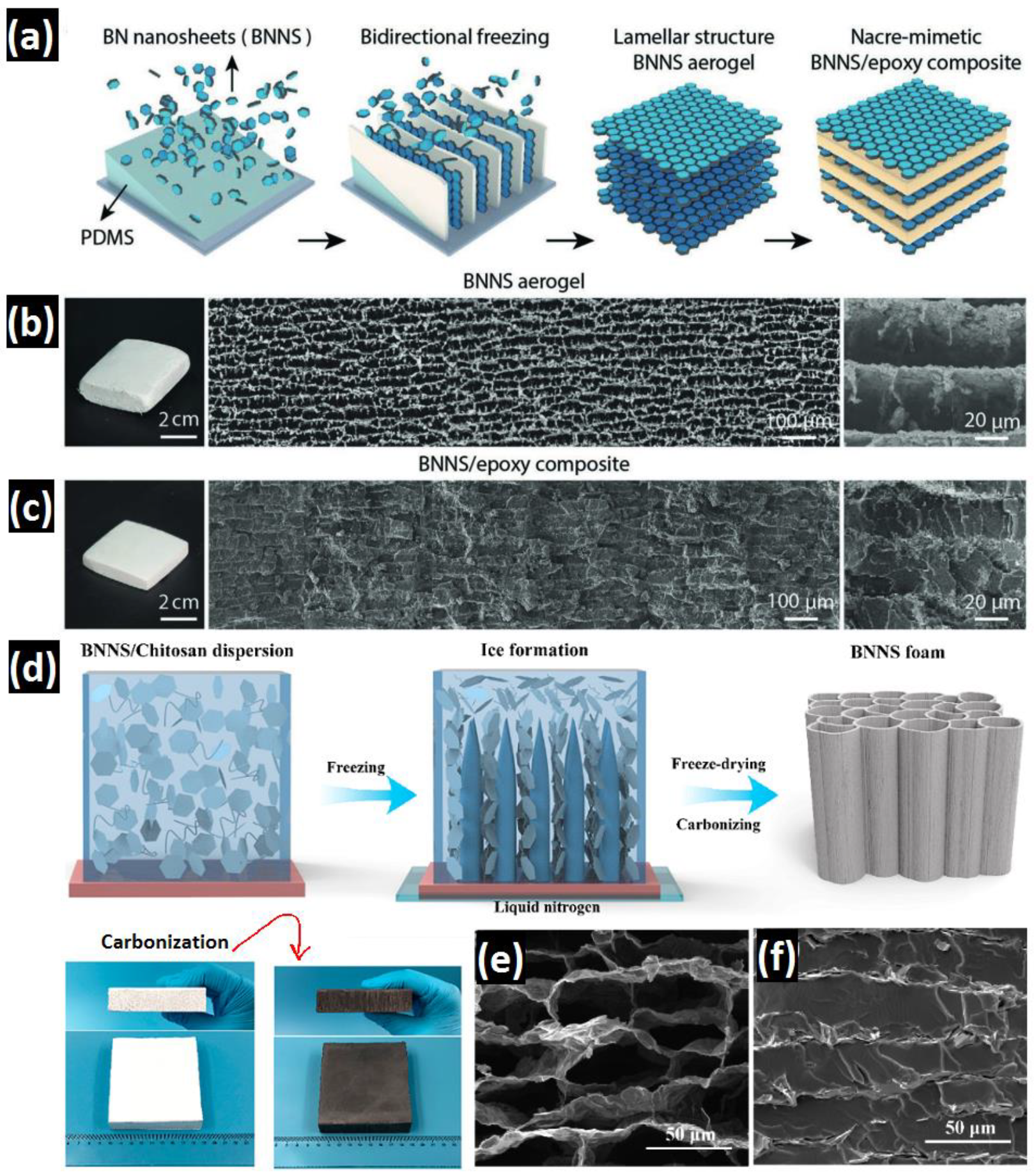
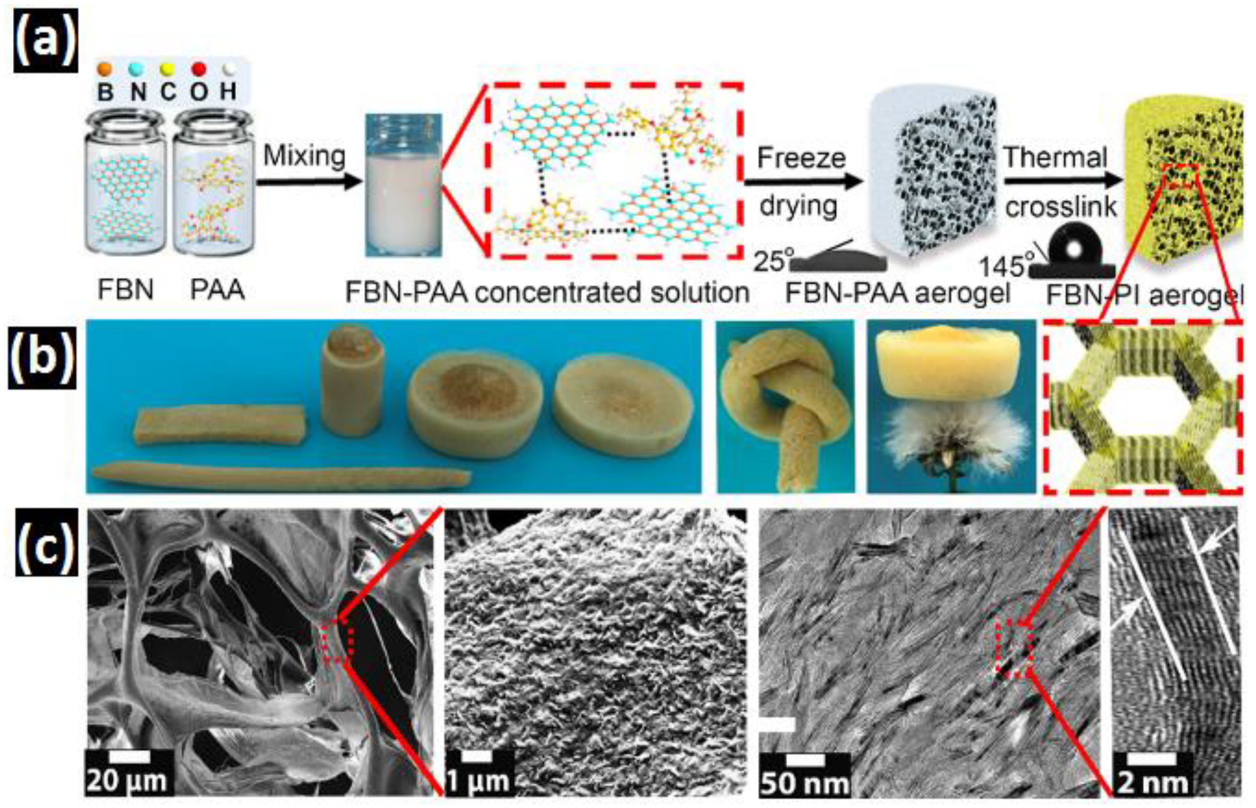
2.3.1. Freeze-Drying
2.3.2. Template-Assisted
- Over-saturated NaCl solution as a result of water evaporation embarks NaCl recrystallization on the surface of h-BN; PVA, as a binding agent, fixes recrystallized NaCl particles on h-BN surface. Then the PVA/NaCl/h-BN mixture gradually becomes flocculated.
- Flocculated seeds are accumulated, enlarge to minimize surface free energy, leading to the formation of primary BNMBs particles.
- By losing more water, more NaCl/h-BN particles joined the primary particles, giving rise to the formation of spherical secondary BNMBs particles.
- Upon template removal through cold water, the recrystallization is exterminated and hollow BNMBs can be obtained.
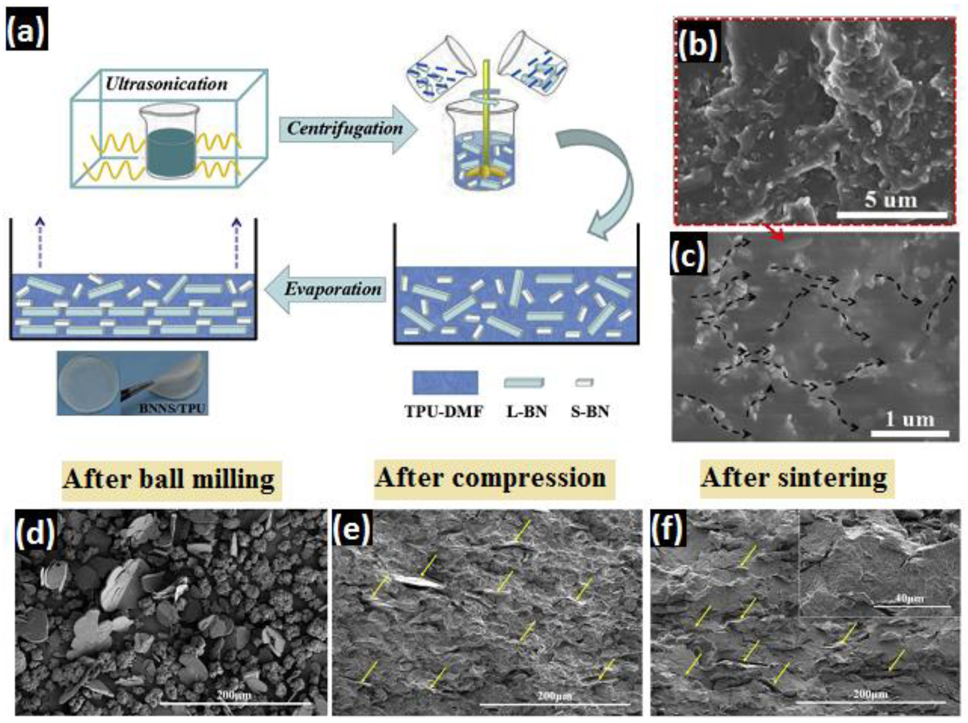
2.3.3. Mechanical Milling
2.3.4. Magnetic/Electric-Field Assisted
2.3.5. Other Synthesis Methods
2.4. Thermal Conductivity Evaluations of h-BN-Reinforced Polymer Composites
2.4.1. h-BN as a Single Filler
2.4.2. h-BN within Hybrid Filler Configurations
3. Tribological Properties
3.1. Tribology Theory
3.1.1. Friction
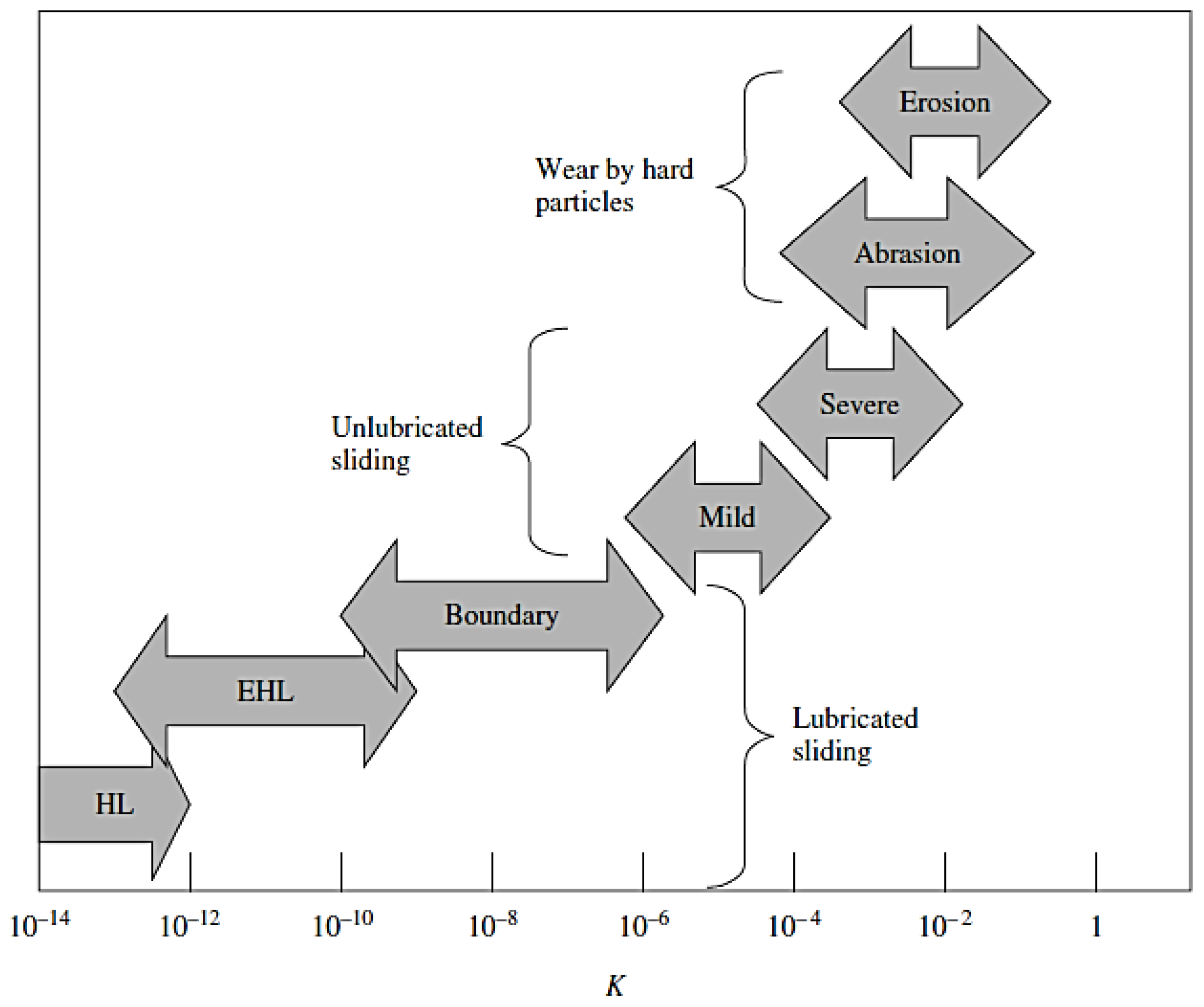
3.1.2. Wear
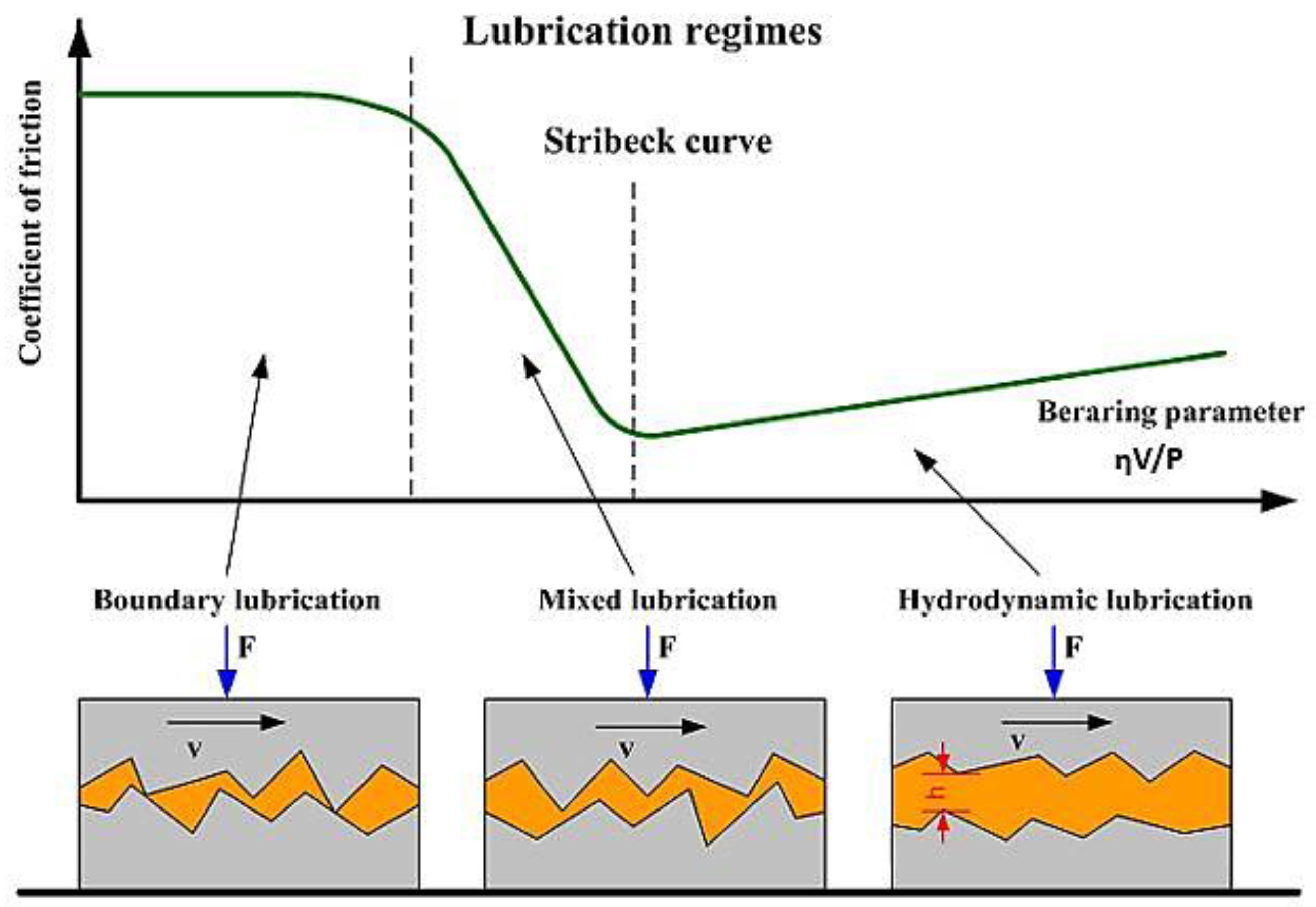
3.1.3. Lubrication
3.1.4. Solid Lubrication
3.1.5. Materials Development
PMC
Ceramic Matrix Composite (CMC):
Metal Matrix Composite (MMC):


3.2. Lubrication Additive


| Matrix | Filler & Content | Procedure | COF | Wear Rate | Other Features | Ref. |
|---|---|---|---|---|---|---|
| Poly aryl ether ketone (PAEK) | h-BN (10 wt.%) | Hot air circling and injection molding | Minimum COF was shown in composite with 10 wt.% of h-BN | Minimum wear rate was shown in composite with 10 wt.% of h-BN | Self-lubrication nature of BN | [174] |
| PAEK | h-BN in a combination of micro 7% and nano 3% | Magnetic stirring and injection molding | With micro h-BN = 0.055 With micro and nano h-BN = 0.046 | - | Fiber damage in micron size. Flat surface of fiber and no de-bonding of fibers in nano size | [143] |
| Epoxy | Nano h-BN (1 wt.%) | Liquid casting method | Lowest COF at 1 wt.% h-BN which was 0.48 | Lowest wear rate at 1 wt.% h-BN which was 3 × 10⁻⁵ mm3·N−1·m−1 | Restricting crack development by BN and higher lubricity | [175] |
| Epoxy | 0.5 wt.% of c-BN and h-BN | Exfoliation and ultrasonic treatment | COF with 0.5 wt.% c-BN/Epoxy: 9.74% lower than epoxy COF with 0.5 wt.% h-BN/Epoxy: 12.4% lower than epoxy | Wear rate of 0.5 wt.% c-BN/epoxy: 5.6 × 10⁻⁴ mm3·N−1·m−1 Wear rate of 0.5 wt.% h-BN/epoxy: 5.88 × 10⁻⁴ mm3·N−1·m−1 Wear rate of epoxy: 22.28 × 10⁻⁴ mm3·N−1·m−1 | Removing direct contact between sliding surfaces and less adhesive wear | [140] |
| Epoxy | h-BN and c-BN | Heat treated, centrifuged, and dried in furnace | In dry sliding with h-BN = 0.62 In dry sliding with c-BN = 0.73 | Wear rate in dry sliding with h-BN was higher than c-BN | Lower wear rate with c-BN is due to its hardness and hard particles of it in sliding interface increases the COF | [141] |
| Polyoxymethylene (POM) | 3% h-BN (POM/10CF-3h-BN) | Hot press and heating at 190 °C | With 3% h-BN was between 0.13 to 0.14 in different loadings | Wear rate with 3% h-BN = 6.3 × 10⁻⁷ mm3·N−1·m−1 | Synergetic role of h-BN and carbon fiber | [137] |
| B4C | h-BN (20 wt.%) | Hot press sintering under 350 MPa at 1800 °C for 60 min | Without h-BN = 0.38 With 20 wt.% h-BN = 0.005 | Lowest wear rate was shown in 20 wt.% of h-BN | Formation of a tribo-film on the wearing surface | [29] |
| B4C | h-BN (30 wt.%) | Hot press sintering under 350 MPa at 1800 °C, for 60 min | Without h-BN = 0.58 With 30 wt.% h-BN = 0.38 | Lower wear coefficient with increasing h-BN content; Lowest wear coefficient in 30 wt.% of h-BN | Formation of a transfer film on the wearing surface, the reduction of the percentage of hard particles | [176] |
| Si3N4 | h-BN (20 wt.%) | Hot press sintering under 30 MPa at 1800 °C for dwell time of 30 min | Without h-BN = 0.58 With 20 wt.% h-BN = 0.302 | Minimum wear rate was 2.93 × 10⁻⁶ mm3·N−1·m−1 in 20 wt.% of h-BN | Forming a tribo-chemical film in contact surface of sliding pair | [150] |
| Si3N4 | h-BN (20 wt.%) | Hot pressing | Without h-BN = 0.58 With 20 wt.% h-BN = 0.31 | Lowest wear rate at 20 wt.% h-BN | Forming a tribo-film of metal oxide | [177] |
| c-BN | h-BN (5 to 15 wt.%) | Ball mixing for 30 min and sintering at 880 °C for 30 min | With 5 wt.% h-BN = 0.7 With 15 wt.% h-BN = 0.3 | Wear volume in 5 wt.% h-BN = 0.126 mm3·N−1·m−1 wear volume in 15 wt.% h-BN = 0.135 mm3·N−1·m−1 | Forming a tribo-layer in friction interface | [148] |
| CNT | h-BN0.75C0.25, h-BN0.5C0.5, h-.25C0.75 | Covalent crosslinking | Lowest COF was shown in BN0.5C0.5 | Lowest wear rate achieved for BN0.5C0.5 | Smooth worn surface due to a tribo-film | [151] |
| AA6082 | TiB2 and h-BN (50% TiB2 + 50% h-BN) | Friction stir processing | Lower COF with increasing h-BN | Wear rate of AA6082 = 23.75 × 10⁻⁵ mm3·N−1·m−1 wear rate of AA6082/50% TiB2 + 50% h-BN = 13 × 10−5 mm3·N−1·m−1 | Change of wear mechanism from adhesive to abrasive due to TiB2 and BN in the wear interface | [156] |
| Fe–Si–C | h-BN and graphite (10% of lubricant containing h-BN: 1 vol.% and graphite: 9 vol.%) | Isothermal sintering at 500 °C for 30 min | Lowest COF in the composite with 1 vol.% of h-BN and 9 vol.% of graphite | An improvement in wear resistance in the composite with 1 vol.% of h-BN and 9 vol.% of graphite | Formation of a oxide layer due to tribo-chemical reaction | [163] |
| Ni–Ag–Al–MoS2 | h-BN (5 wt.%) | Ball milling for 8 h at 200 rpm | Without = 0.32 With 5 wt.% h-BN = 0.23 | Lowest wear rate was found in 5 wt.% h-BN | No direct contact between sliding pair due to a tribo-layer formation | [161] |
| Ni60 | Nano-Cu and h-BN (from room temperature to 600 °C) | Ball milling for 3 h at 300 rpm, Laser cladding at 3 kW and scanning speed of 2 mm s−1 | At all temperatures: minimum COF was found with nano-Cu and h-BN lubricant and it was 0.323 at 600 °C | At all temperatures Ni60 with nano-Cu and h-BN lubricant showed the minimum wear rate | Change of wear mechanism from abrasive to adhesive above 400 °C | [178] |
| Ni3Al | h-BN nano plate (BNNP) | Electrostatic absorption dispersion method | Without BNNP = 0.30 With BNNP = 0.22 | Depth of wear track for Ni3Al = 0.35 µm, depth of wear track for Ni3Al/BNNP = 0.28 µm | Weight loss resistance due to self-lubrication characteristic | [159] |
| Al6061 | h-BN and Al2O3 (30 h-BN-10 Al2O3-5 C) | Stir casting | - | Lowest wear rate for 30 h-BN-10 Al2O3-5 C due to hard h-BN and Al2O3 particles reinforcement | Self-lubrication nature of BN and C. Wear mechanism was adhesive. | [179] |
| Co | 10 wt.% h-BN | Ball milling and cladding on a die steel sheet | Without h-BN = 0.52 With 10 wt.% h-BN = 0.422 | Wear rate with 10 wt.% h-BN = 7.5 × 10⁻⁵ mm3·N−1·m−1 Wear rate with 10 wt.% h-BN = 24.9 × 10⁻⁵ mm3·N−1·m−1 | Improvement in lubricity and changing the wear mechanism due to lubricating characteristic of h-BN | [180] |
| Cu | 2.5 wt.% h-BN | Electroless deposition | Without h-BN = 0.37 with 2.5 wt.% h-BN = 0.008 | Wear rate increases with higher amount of h-BN | Higher wear rate with addition of h-BN is due to the low shear strength. Reduction in COF attributes to lubricity of h-BN | [155] |
4. Conclusions and Future Perspectives
Author Contributions
Funding
Conflicts of Interest
References
- Novoselov, K.S.; Geim, A.K.; Morozov, S.V.; Jiang, D.; Zhang, Y.; Dubonos, S.V.; Grigorieva, I.V.; Firsov, A.A. Electric Field Effect in Atomically Thin Carbon Films. Science 2004, 306, 666–669. [Google Scholar] [CrossRef] [PubMed] [Green Version]
- Liu, X.; Ma, T.; Pinna, N.; Zhang, J. Two-Dimensional Nanostructured Materials for Gas Sensing. Adv. Funct. Mater. 2017, 27, 1702168. [Google Scholar] [CrossRef]
- Zhang, X.; Lai, Z.; Tan, C.; Zhang, H. Solution-Processed Two-Dimensional MoS2Nanosheets: Preparation, Hybridization, and Applications. Angew. Chemie Int. Ed. Engl. 2016, 55, 8816–8838. [Google Scholar] [CrossRef] [PubMed]
- Khalaj, M.; Sedghi, A.; Miankushki, H.N.; Golkhatmi, S.Z. Synthesis of novel graphene/Co3O4/polypyrrole ternary nanocomposites as electrochemically enhanced supercapacitor electrodes. Energy 2019, 188, 116088. [Google Scholar] [CrossRef]
- Golkhatmi, S.Z.; Khalaj, M.; Izadpanahi, A.; Sedghi, A. One-step electrodeposition synthesis of high performance Graphene/Cu2O nanocomposite films on copper foils as binder-free supercapacitor electrodes. Solid State Sci. 2020, 106, 106336. [Google Scholar] [CrossRef]
- Gogotsi, Y.; Anasori, B. The Rise of MXenes. ACS Nano 2019, 13, 8491–8494. [Google Scholar] [CrossRef] [Green Version]
- Anasori, B.; Lukatskaya, M.R.; Gogotsi, Y. 2D metal carbides and nitrides (MXenes) for energy storage. Nat. Rev. Mater. 2017, 2. [Google Scholar] [CrossRef]
- Li, X.; Shan, J.; Zhang, W.; Su, S.; Yuwen, L.; Wang, L. Recent Advances in Synthesis and Biomedical Applications of Two-Dimensional Transition Metal Dichalcogenide Nanosheets. Small 2017, 13, 1602660. [Google Scholar] [CrossRef]
- Bollella, P.; Fusco, G.; Tortolini, C.; Sanzò, G.; Favero, G.; Gorton, L.; Antiochia, R. Beyond graphene: Electrochemical sensors and biosensors for biomarkers detection. Biosens. Bioelectron. 2017, 89, 152–166. [Google Scholar] [CrossRef]
- Zhang, K.; Feng, Y.; Wang, F.; Yang, Z.; Wang, J. Two dimensional hexagonal boron nitride (2D-hBN): Synthesis, properties and applications. J. Mater. Chem. C. 2017, 5, 11992–12022. [Google Scholar] [CrossRef]
- Lin, Y.; Connell, J.W. Advances in 2D boron nitride nanostructures: Nanosheets, nanoribbons, nanomeshes, and hybrids with graphene. Nanoscale 2012, 4, 6908–6939. [Google Scholar] [CrossRef] [PubMed]
- Guerra, V.; Wan, C.; McNally, T. Thermal conductivity of 2D nano-structured boron nitride (BN) and its composites with polymers. Prog. Mater. Sci. 2019, 100, 170–186. [Google Scholar] [CrossRef]
- Yin, J.; Li, J.; Hang, Y.; Yu, J.; Tai, G.; Li, X.; Zhang, Z.; Guo, W. Boron Nitride Nanostructures: Fabrication, Functionalization and Applications. Small 2016, 12, 2942–2968. [Google Scholar] [CrossRef]
- Giovannetti, G.; Khomyakov, P.A.; Brocks, G.; Kelly, P.J.; van den Brink, J. Substrate-induced band gap in graphene on hexagonal boron nitride: Ab initio density functional calculations. Phys. Rev. B. 2007, 76, 73103. [Google Scholar] [CrossRef] [Green Version]
- Glavin, N.R.; Jespersen, M.L.; Check, M.H.; Hu, J.; Hilton, A.M.; Fisher, T.S.; Voevodin, A.A. Synthesis of few-layer, large area hexagonal-boron nitride by pulsed laser deposition. Thin Solid Film 2014, 572, 245–250. [Google Scholar] [CrossRef]
- Meric, I.; Dean, C.R.; Petrone, N.; Wang, L.; Hone, J.; Kim, P.; Shepard, K.L. Graphene Field-Effect Transistors Based on Boron–Nitride Dielectrics. Proc. IEEE 2013, 101, 1609–1619. [Google Scholar] [CrossRef]
- Fu, L.; Lai, G.; Chen, G.; Lin, C.-T.; Yu, A. Microwave Irradiation-Assisted Exfoliation of Boron Nitride Nanosheets: A Platform for Loading High Density of Nanoparticles. Chem. Sel. 2016, 1, 1799–1803. [Google Scholar] [CrossRef]
- Li, L.H.; Chen, Y. Atomically Thin Boron Nitride: Unique Properties and Applications. Adv. Funct. Mater. 2016, 26, 2594–2608. [Google Scholar] [CrossRef] [Green Version]
- Byun, S.; Kim, J.H.; Song, S.H.; Lee, M.; Park, J.J.; Lee, G.; Hong, S.H.; Lee, D. Ordered, Scalable Heterostructure Comprising Boron Nitride and Graphene for High-Performance Flexible Supercapacitors. Chem. Mater. 2016, 28, 7750–7756. [Google Scholar] [CrossRef]
- Gao, T.; Gong, L.; Wang, Z.; Yang, Z.; Pan, W.; He, L.; Zhang, J.; Ou, E.; Xiong, Y.; Xu, W. Boron nitride/reduced graphene oxide nanocomposites as supercapacitors electrodes. Mater. Lett. 2015, 159, 54–57. [Google Scholar] [CrossRef]
- Khan, A.F.; Down, M.P.; Smith, G.C.; Foster, C.W.; Banks, C.E. Surfactant-exfoliated 2D hexagonal boron nitride (2D-hBN): Role of surfactant upon the electrochemical reduction of oxygen and capacitance applications. J. Mater. Chem. A 2017, 5, 4103–4113. [Google Scholar] [CrossRef] [Green Version]
- Angizi, S.; Hatamie, A.; Ghanbari, H.; Simchi, A. Mechanochemical Green Synthesis of Exfoliated Edge-Functionalized Boron Nitride Quantum Dots: Application to Vitamin C Sensing through Hybridization with Gold Electrodes. ACS Appl. Mater. Interfaces 2018, 10, 28819–28827. [Google Scholar] [CrossRef] [PubMed]
- Ivanova, M.N.; Grayfer, E.D.; Plotnikova, E.E.; Kibis, L.S.; Darabdhara, G.; Boruah, P.K.; Das, M.R.; Fedorov, V.E. Pt-Decorated Boron Nitride Nanosheets as Artificial Nanozyme for Detection of Dopamine. ACS Appl. Mater. Interfaces 2019, 11, 22102–22112. [Google Scholar] [CrossRef] [PubMed]
- Angizi, S.; Shayeganfar, F.; Azar, M.H.; Simchi, A. Surface/edge functionalized boron nitride quantum dots: Spectroscopic fingerprint of bandgap modification by chemical functionalization. Ceram. Int. 2020, 46, 978–985. [Google Scholar] [CrossRef]
- Hatamie, A.; Rahmati, R.; Rezvani, E.; Angizi, S.; Simchi, A. Yttrium hexacyanoferrate microflowers on freestanding three-dimensional graphene substrates for ascorbic acid detection. ACS Appl. Nano Mater. 2019, 2, 2212–2221. [Google Scholar] [CrossRef]
- Guo, Y.; Lyu, Z.; Yang, X.; Lu, Y.; Ruan, K.; Wu, Y.; Kong, J.; Gu, J. Enhanced thermal conductivities and decreased thermal resistances of functionalized boron nitride/polyimide composites. Compos. Part B Eng. 2019, 164, 732–739. [Google Scholar] [CrossRef]
- Isarn, I.; Bonnaud, L.; Massagués, L.; Serra, À.; Ferrando, F. Enhancement of thermal conductivity in epoxy coatings through the combined addition of expanded graphite and boron nitride fillers. Prog. Org. Coat. 2019, 133, 299–308. [Google Scholar] [CrossRef]
- Zhu, S.; Cheng, J.; Qiao, Z.; Yang, J. High temperature solid-lubricating materials: A review. Tribol. Int. 2019, 133, 206–223. [Google Scholar] [CrossRef]
- Li, X.; Gao, Y.; Yang, Q.; Pan, W.; Li, Y.; Zhong, Z.; Song, L. Evaluation of tribological behavior of B4C—hBN ceramic composites under water-lubricated condition. Ceram. Int. 2015, 41, 7387–7393. [Google Scholar] [CrossRef]
- Burger, N.; Laachachi, A.; Ferriol, M.; Lutz, M.; Toniazzo, V.; Ruch, D. Review of thermal conductivity in composites: Mechanisms, parameters and theory. Prog. Polym. Sci. 2016, 61, 1–28. [Google Scholar] [CrossRef]
- Leven, I.; Krepel, D.; Shemesh, O.; Hod, O. Robust Superlubricity in Graphene/h-BN Heterojunctions. J. Phys. Chem. Lett. 2013, 4, 115–120. [Google Scholar] [CrossRef] [PubMed] [Green Version]
- Yuan, C.; Li, J.; Lindsay, L.; Cherns, D.; Pomeroy, J.W.; Liu, S.; Edgar, J.H.; Kuball, M. Modulating the thermal conductivity in hexagonal boron nitride via controlled boron isotope concentration. Commun. Phys. 2019, 2, 1–8. [Google Scholar] [CrossRef]
- Zhang, Y.F.; Chen, L.; Ge, Y.Y.; Wang, Q.Y.; Bai, S.L. Graphite tube woven fabric/boron nitride/polymer composite with enhanced thermal conductivity and electric isolation. Polym. Compos. 2019, 40, E1808–E1817. [Google Scholar] [CrossRef]
- Pakdel, A.; Bando, Y.; Golberg, D. Nano boron nitride flatland. Chem. Soc. Rev. 2014, 43, 934–959. [Google Scholar] [CrossRef]
- Park, O.K.; Owuor, P.S.; Jaques, Y.M.; Galvao, D.S.; Kim, N.H.; Lee, J.H.; Tiwary, C.S.; Ajayan, P.M. Hexagonal boron nitride-carbon nanotube hybrid network structure for enhanced thermal, mechanical and electrical properties of polyimide nanocomposites. Compos. Sci. Technol. 2020, 188, 107977. [Google Scholar] [CrossRef]
- Paszkiewicz, S.; Taraghi, I.; Szymczyk, A.; Huczko, A.; Kurcz, M.; Przybyszewski, B.; Stanik, R.; Linares, A.; Ezquerra, T.A.; Rosłaniec, Z. Electrically and thermally conductive thin elastic polymer foils containing SiC nanofibers. Compos. Sci. Technol. 2017, 146, 20–25. [Google Scholar] [CrossRef]
- Shen, D.; Zhan, Z.; Liu, Z.; Cao, Y.; Zhou, L.; Liu, Y.; Dai, W.; Nishimura, K.; Li, C.; Lin, C.T.; et al. Enhanced thermal conductivity of epoxy composites filled with silicon carbide nanowires. Sci. Rep. 2017, 7, 1–11. [Google Scholar] [CrossRef] [Green Version]
- Yin, L.; Zhou, X.; Yu, J.; Wang, H.; Ran, C. Fabrication of a polymer composite with high thermal conductivity based on sintered silicon nitride foam. Compos. Part A Appl. Sci. Manuf. 2016, 90, 626–632. [Google Scholar] [CrossRef]
- Akhtar, M.W.; Lee, Y.S.; Yoo, D.J.; Kim, J.S. Alumina-graphene hybrid filled epoxy composite: Quantitative validation and enhanced thermal conductivity. Compos. Part B Eng. 2017, 131, 184–195. [Google Scholar] [CrossRef]
- Li, S.; Feng, Y.; Li, Y.; Feng, W.; Yoshino, K. Transparent and flexible films of horizontally aligned carbon nanotube/polyimide composites with highly anisotropic mechanical, thermal, and electrical properties. Carbon N. Y. 2016, 109, 131–140. [Google Scholar] [CrossRef]
- Xu, L.; Chen, G.; Wang, W.; Li, L.; Fang, X. A facile assembly of polyimide/graphene core-shell structured nanocomposites with both high electrical and thermal conductivities. Compos. Part A Appl. Sci. Manuf. 2016, 84, 472–481. [Google Scholar] [CrossRef]
- Cho, H.B.; Konno, A.; Fujihara, T.; Suzuki, T.; Tanaka, S.; Jiang, W.; Suematsu, H.; Niihara, K.; Nakayama, T. Self-assemblies of linearly aligned diamond fillers in polysiloxane/diamond composite films with enhanced thermal conductivity. Compos. Sci. Technol. 2011, 72, 112–118. [Google Scholar] [CrossRef]
- Ji, T.; Feng, Y.; Qin, M.; Li, S.; Zhang, F.; Lv, F.; Feng, W. Thermal conductive and flexible silastic composite based on a hierarchical framework of aligned carbon fibers-carbon nanotubes. Carbon N. Y. 2018, 131, 149–159. [Google Scholar] [CrossRef]
- Li, J.; Qi, S.; Li, J.; Zhang, M.; Wang, Z. A highly thermostable and transparent lateral heat spreader based on silver nanowire/polyimide composite. RSC Adv. 2015, 5, 59398–59402. [Google Scholar] [CrossRef]
- Yu, S.; Lee, J.W.; Han, T.H.; Park, C.; Kwon, Y.; Hong, S.M.; Koo, C.M. Copper shell networks in polymer composites for efficient thermal conduction. ACS Appl. Mater. Interfaces. 2013, 5, 11618–11622. [Google Scholar] [CrossRef] [PubMed]
- Chung, S.; Im, Y.; Kim, H.; Park, S.; Jeong, H. Evaluation for micro scale structures fabricated using epoxy-aluminum particle composite and its application. J. Mater. Process. Technol. 2005, 160, 168–173. [Google Scholar] [CrossRef]
- Duan, G.; Wang, Y.; Yu, J.; Zhu, J.; Hu, Z. Improved thermal conductivity and dielectric properties of flexible PMIA composites with modified micro- and nano-sized hexagonal boron nitride. Front. Mater. Sci. 2019, 13, 64–76. [Google Scholar] [CrossRef]
- Yang, D.; Ni, Y.; Kong, X.; Gao, D.; Wang, Y.; Hu, T.; Zhang, L. Mussel-inspired modification of boron nitride for natural rubber composites with high thermal conductivity and low dielectric constant. Compos. Sci. Technol. 2019, 177, 18–25. [Google Scholar] [CrossRef]
- Zhang, R.H.; Shi, X.T.; Tang, L.; Liu, Z.; Zhang, J.L.; Guo, Y.Q.; Gu, J.W. Thermally Conductive and Insulating Epoxy Composites by Synchronously Incorporating Si-sol Functionalized Glass Fibers and Boron Nitride Fillers. Chin. J. Polym. Sci. 2020, 38, 730–739. [Google Scholar] [CrossRef]
- Lewis, J.S.; Barani, Z.; Magana, A.S.; Kargar, F.; Balandin, A.A. Thermal and electrical conductivity control in hybrid composites with graphene and boron nitride fillers. Mater. Res. Express. 2019, 6, 085325. [Google Scholar] [CrossRef] [Green Version]
- Mai, V.D.; Lee, D.-I.; Park, J.H.; Lee, D.S. Rheological properties and thermal conductivity of epoxy resins filled with a mixture of alumina and boron nitride. Polymers 2019, 11, 597. [Google Scholar] [CrossRef] [PubMed] [Green Version]
- Han, J.; Du, G.; Gao, W.; Bai, H. An Anisotropically High Thermal Conductive Boron Nitride/Epoxy Composite Based on Nacre-Mimetic 3D Network. Adv. Funct. Mater. 2019, 29, 1–9. [Google Scholar] [CrossRef]
- Hou, X.; Chen, Y.; Lv, L.; Dai, W.; Zhao, S.; Wang, Z.; Fu, L.; Lin, C.T.; Jiang, N.; Yu, J. High-Thermal-Transport-Channel Construction within Flexible Composites via the Welding of Boron Nitride Nanosheets. ACS Appl. Nano Mater. 2019, 2, 360–368. [Google Scholar] [CrossRef]
- Wang, J.; Liu, D.; Li, Q.; Chen, C.; Chen, Z.; Song, P.; Hao, J.; Li, Y.; Fakhrhoseini, S.; Naebe, M.; et al. Lightweight, Superelastic Yet Thermoconductive Boron Nitride Nanocomposite Aerogel for Thermal Energy Regulation. ACS Nano 2019. [Google Scholar] [CrossRef] [PubMed]
- Wang, X.; Wu, P. Preparation of Highly Thermally Conductive Polymer Composite at Low Filler Content via a Self-Assembly Process between Polystyrene Microspheres and Boron Nitride Nanosheets. ACS Appl. Mater. Interfaces 2017, 9, 19934–19944. [Google Scholar] [CrossRef] [PubMed]
- Nagaoka, S.; Jodai, T.; Kameyama, Y.; Horikawa, M.; Shirosaki, T.; Ryu, N.; Takafuji, M.; Sakurai, H.; Ihara, H. Cellulose/boron nitride core–shell microbeads providing high thermal conductivity for thermally conductive composite sheets. RSC Adv. 2016, 6, 33036–33042. [Google Scholar] [CrossRef]
- Sun, J.; Wang, D.; Yao, Y.; Zeng, X.; Pan, G.; Huang, Y.; Hu, J.; Sun, R.; Xu, J.; Wong, C. Boron nitride microsphere/epoxy composites with enhanced thermal conductivity. High Volt. 2017, 2, 147–153. [Google Scholar] [CrossRef]
- Xiao, C.; Tang, Y.; Chen, L.; Zhang, X.; Zheng, K.; Tian, X. Preparation of highly thermally conductive epoxy resin composites via hollow boron nitride microbeads with segregated structure. Compos. Part A Appl. Sci. Manuf. 2019, 121, 330–340. [Google Scholar] [CrossRef]
- Zhu, Z.; Li, C.; Songfeng, E.; Xie, L.; Geng, R.; Lin, C.T.; Li, L.; Yao, Y. Enhanced thermal conductivity of polyurethane composites via engineering small/large sizes interconnected boron nitride nanosheets. Compos. Sci. Technol. 2019, 170, 93–100. [Google Scholar] [CrossRef]
- Wang, H.; Ding, D.; Liu, Q.; Chen, Y.; Zhang, Q. Highly anisotropic thermally conductive polyimide composites via the alignment of boron nitride platelets. Compos. Part B Eng. 2019, 158, 311–318. [Google Scholar] [CrossRef]
- Tian, C.; Yuan, L.; Liang, G.; Gu, A. High thermal conductivity and flame-retardant phosphorus-free bismaleimide resin composites based on 3D porous boron nitride framework. J. Mater. Sci. 2019, 54, 7651–7664. [Google Scholar] [CrossRef]
- Yuan, J.; Qian, X.; Meng, Z.; Yang, B.; Liu, Z.Q. Highly Thermally Conducting Polymer-Based Films with Magnetic Field-Assisted Vertically Aligned Hexagonal Boron Nitride for Flexible Electronic Encapsulation. ACS Appl. Mater. Interfaces 2019, 11, 17915–17924. [Google Scholar] [CrossRef] [PubMed]
- Xue, Y.; Li, X.; Wang, H.; Zhao, F.; Zhang, D.; Chen, Y. Improvement in thermal conductivity of through-plane aligned boron nitride/silicone rubber composites. Mater. Des. 2019, 165, 107580. [Google Scholar] [CrossRef]
- Liang, W.; Ge, X.; Ge, J.; Li, T.; Zhao, T.; Chen, X.; Zhang, M.; Ji, J.; Pang, X.; Liu, R. Three-dimensional heterostructured reduced graphene oxide-hexagonal boron nitride-stacking material for silicone thermal grease with enhanced thermally conductive properties. Nanomaterials 2019, 9, 938. [Google Scholar] [CrossRef] [PubMed] [Green Version]
- Lin, Z.; Liu, Y.; Raghavan, S.; Moon, K.; Sitaraman, S.K.; Wong, C. Magnetic Alignment of Hexagonal Boron Nitride Platelets in Polymer Matrix: Toward High Performance Anisotropic Polymer Composites for Electronic Encapsulation. ACS Appl. Mater. Interfaces 2013, 5, 7633–7640. [Google Scholar] [CrossRef] [PubMed]
- Yuan, C.; Duan, B.; Li, L.; Xie, B.; Huang, M.; Luo, X. Thermal Conductivity of Polymer-Based Composites with Magnetic Aligned Hexagonal Boron Nitride Platelets. ACS Appl. Mater. Interfaces 2015, 7, 13000–13006. [Google Scholar] [CrossRef] [PubMed]
- Yuan, C.; Li, L.; Duan, B.; Xie, B.; Zhu, Y.; Luo, X. Locally reinforced polymer-based composites for efficient heat dissipation of local heat source. Int. J. Therm. Sci. 2016, 102, 202–209. [Google Scholar] [CrossRef] [Green Version]
- Li, Y.; Tian, X.; Yang, W.; Li, Q.; Hou, L.; Zhu, Z.; Tang, Y.; Wang, M.; Zhang, B.; Pan, T.; et al. Dielectric composite reinforced by in-situ growth of carbon nanotubes on boron nitride nanosheets with high thermal conductivity and mechanical strength. Chem. Eng. J. 2019, 358, 718–724. [Google Scholar] [CrossRef]
- Chen, J.; Huang, X.; Sun, B.; Wang, Y.; Zhu, Y.; Jiang, P. Vertically Aligned and Interconnected Boron Nitride Nanosheets for Advanced Flexible Nanocomposite Thermal Interface Materials. ACS Appl. Mater. Interfaces 2017, 9, 30909–30917. [Google Scholar] [CrossRef]
- Agari, Y.; Ueda, A.; Nagai, S. Thermal conductivity of a polymer composite. J. Appl. Polym. Sci. 1993, 49, 1625–1634. [Google Scholar] [CrossRef]
- Xiao, Y.; Wang, W.; Lin, T.; Chen, X.; Zhang, Y.; Yang, J.; Wang, Y.; Zhou, Z. Largely enhanced thermal conductivity and high dielectric constant of poly (vinylidene fluoride)/boron nitride composites achieved by adding a few carbon nanotubes. J. Phys. Chem. C 2016, 120, 6344–6355. [Google Scholar] [CrossRef]
- Feng, Y.; Han, G.; Wang, B.; Zhou, X.; Ma, J.; Ye, Y.; Liu, C.; Xie, X. Multiple synergistic effects of graphene-based hybrid and hexagonal born nitride in enhancing thermal conductivity and flame retardancy of epoxy. Chem. Eng. J. 2020, 379, 122402. [Google Scholar] [CrossRef]
- Mosanenzadeh, S.G.; Khalid, S.; Cui, Y.; Naguib, H.E. High thermally conductive PLA based composites with tailored hybrid network of hexagonal boron nitride and graphene nanoplatelets. Polym. Compos. 2016, 37, 2196–2205. [Google Scholar] [CrossRef]
- Azar, M.H.; Sadri, B.; Nemati, A.; Angizi, S.; Shaeri, M.H.; Minárik, P.; Veselý, J.; Djavanroodi, F. Investigating the microstructure and mechanical properties of aluminum-matrix reinforced- graphene nanosheet composites fabricated by mechanical milling and equal-channel angular pressing. Nanomaterials 2019, 9, 1070. [Google Scholar] [CrossRef] [Green Version]
- Fan, Y.; Cho, U.R. Effects of graphite and boron nitride based fillers on mechanical, thermal conductive, and thermo-physical properties in solution styrene–butadiene rubber. Polym. Compos. 2019, 40, E1426–E1433. [Google Scholar] [CrossRef]
- Yuan, F.-Y.; Zhang, H.-B.; Li, X.; Li, X.-Z.; Yu, Z.-Z. Synergistic effect of boron nitride flakes and tetrapod-shaped ZnO whiskers on the thermal conductivity of electrically insulating phenol formaldehyde composites. Compos. Part A Appl. Sci. Manuf. 2013, 53, 137–144. [Google Scholar] [CrossRef]
- Liu, M.; Chiang, S.-W.; Chu, X.; Li, J.; Gan, L.; He, Y.; Li, B.; Kang, F.; Du, H. Polymer composites with enhanced thermal conductivity via oriented boron nitride and alumina hybrid fillers assisted by 3-D printing. Ceram. Int. 2020. [Google Scholar] [CrossRef]
- Yang, Q.; Zhang, Z.; Gong, X.; Yao, E.; Liu, T.; Zhang, Y.; Zou, H. Thermal conductivity of Graphene-polymer composites: Implications for thermal management. Heat Mass Transf. 2020, 56, 1931–1945. [Google Scholar] [CrossRef]
- Bhanuprakash, L.; Ali, A.; Mokkoth, R.; Varghese, S. Mode I and Mode II interlaminar fracture behavior of E-glass fiber reinforced epoxy composites modified with reduced exfoliated graphite oxide. Polym. Compos. 2018, 39, E2506–E2518. [Google Scholar] [CrossRef]
- Ren, D.; Chen, L.; Yuan, Y.; Li, K.; Xu, M.; Liu, X. Designing and preparation of fiber-reinforced composites with enhanced interface adhesion. Polymers 2018, 10, 1128. [Google Scholar] [CrossRef] [Green Version]
- Tang, L.; He, M.; Na, X.; Guan, X.; Zhang, R.; Zhang, J.; Gu, J. Functionalized glass fibers cloth/spherical BN fillers/epoxy laminated composites with excellent thermal conductivities and electrical insulation properties. Compos. Commun. 2019, 16, 5–10. [Google Scholar] [CrossRef]
- Sundararajan, S.; Samui, A.B.; Kulkarni, P.S. Shape-stabilized poly(ethylene glycol) (PEG)-cellulose acetate blend preparation with superior PEG loading via microwave-assisted blending. Sol. Energy 2017, 144, 32–39. [Google Scholar] [CrossRef]
- Nejman, A.; Cieślak, M.; Gajdzicki, B.; Goetzendorf-Grabowska, B.; Karaszewska, A. Methods of PCM microcapsules application and the thermal properties of modified knitted fabric. Thermochim. Acta 2014, 589, 158–163. [Google Scholar] [CrossRef]
- Yang, G.; Wang, B.; Cheng, H.; Mao, Z.; Xu, H.; Zhong, Y.; Feng, X.; Yu, J.; Sui, X. Cellulosic scaffolds doped with boron nitride nanosheets for shape-stabilized phase change composites with enhanced thermal conductivity. Int. J. Biol. Macromol. 2020, 148, 627–634. [Google Scholar] [CrossRef]
- You, J.; Choi, H.-H.; Lee, Y.M.; Cho, J.; Park, M.; Lee, S.-S.; Park, J.H. Plasma-assisted mechanochemistry to produce polyamide/boron nitride nanocomposites with high thermal conductivities and mechanical properties. Compos. Part B Eng. 2019, 164, 710–719. [Google Scholar] [CrossRef]
- Khonsari, M.M.; Booser, E.R. Applied Tribology: Bearing Design and Lubrication; John Wiley & Sons, Ltd.: Hoboken, NJ, USA, 2017. [Google Scholar] [CrossRef]
- Gwidon, W. Stachowiak, Wear–Materials, Mechanisms and Practice; John Wiley & Sons, Ltd.: Hoboken, NJ, USA, 2005. [Google Scholar] [CrossRef]
- Wen, S.; Huang, P. Principles of Tribology; John Wiley & Sons Singapore Pte. Ltd.: Singapore, 2018. [Google Scholar] [CrossRef]
- Bhushan, B.; Ko, P.L. Introduction to Tribology. Appl. Mech. Rev. 2003, 56, B6–B7. [Google Scholar] [CrossRef]
- Finkin, E.F. Speculations on the theory of adhesive wear. Wear 1972, 21, 103–114. [Google Scholar] [CrossRef]
- Abdellah, M.; Fathi, H.; Abdelhaleem, A.; Dewidar, M. Mechanical Properties and Wear Behavior of a Novel Composite of Acrylonitrile–Butadiene–Styrene Strengthened by Short Basalt Fiber. J. Compos. Sci. 2018, 2, 34. [Google Scholar] [CrossRef] [Green Version]
- Janbesarayi, S.M.M.; Mohebi, M.; Baghshahi, S.; Alem, S.A.A.; Irom, E. Preparation of a Mesoporous Ceramic Adsorbent Based on Iranian Domestic Kaolin to Utilize as Slow-Release Urea Fertilizer Medium. Iran. J. Mater. Sci. Eng. 2020, 17, 30–38. [Google Scholar] [CrossRef]
- Yusoff, Z.; Jamaludin, S.B. Tribology and development of wear theory. Int. J. Curr. Res. Rev. 2011, 3, 13–26. [Google Scholar]
- Gunputh, U.F.; Le, H. A Review of In-Situ Grown Nanocomposite Coatings for Titanium Alloy Implant. J. Compos. Sci. 2020, 4, 41. [Google Scholar] [CrossRef] [Green Version]
- Kraiklang, R.; Onwong, J.; Santhaweesuk, C. Multi-Performance Characteristics of AA5052 + 10% SiC Surface Composite by Friction Stir Processing. J. Compos. Sci. 2020, 4, 36. [Google Scholar] [CrossRef] [Green Version]
- Hu, H.; Liu, Z.; Wang, C.; Meng, L.; Shen, Y. Nanomechanical Properties of a Bicomponent Epoxy Resin via Blending with Polyaryletherketone. J. Compos. Sci. 2019, 3, 92. [Google Scholar] [CrossRef] [Green Version]
- Ferreira, F.; Pinheiro, I.; de Souza, S.; Mei, L.; Lona, L. Polymer Composites Reinforced with Natural Fibers and Nanocellulose in the Automotive Industry: A Short Review. J. Compos. Sci. 2019, 3, 51. [Google Scholar] [CrossRef] [Green Version]
- Liu, Q.; Castillo-Rodríguez, M.; Galisteo, A.; de Villoria, R.G.; Torralba, J. Wear Behavior of Copper–Graphite Composites Processed by Field-Assisted Hot Pressing. J. Compos. Sci. 2019, 3, 29. [Google Scholar] [CrossRef] [Green Version]
- Chhetri, S.; Samanta, P.; Murmu, N.; Kuila, T. Anticorrosion Properties of Epoxy Composite Coating Reinforced by Molybdate-Intercalated Functionalized Layered Double Hydroxide. J. Compos. Sci. 2019, 3, 11. [Google Scholar] [CrossRef] [Green Version]
- Chhetri, S.; Adak, N.; Samanta, P.; Murmu, N.; Kuila, T. Exploration of Mechanical and Thermal Properties of CTAB-Modified MoS2/LLDPE Composites Prepared by Melt Mixing. J. Compos. Sci. 2018, 2, 37. [Google Scholar] [CrossRef] [Green Version]
- Joseph, J.; Sharma, A.; Sahoo, B.; Paul, J.; Sidpara, A.M. PVA/MLG/MWCNT hybrid composites for X band EMI shielding—Study of mechanical, electrical, thermal and tribological properties. Mater. Today Commun. 2020, 23, 100941. [Google Scholar] [CrossRef]
- Chen, P.; Zhang, Y.; Zhang, Z.; Li, R.; Zeng, S. Tuning the microstructure, mechanical properties, and tribological behavior of in-situ VCp-reinforced Fe―Matrix composites via manganese-partitioning treatment. Mater. Today Commun. 2020, 24, 101135. [Google Scholar] [CrossRef]
- Cao, X.; Wang, J.; Liang, Y.; Zhang, G.; Shang, L.; Lu, Z.; Xue, Q. Corrosion and tribological investigations of the B4C coatings rubbing against SiC ball for high relative humidity engineering application. Mater. Today Commun. 2020, 23, 100924. [Google Scholar] [CrossRef]
- Hou, W.; Gao, Y.; Wang, J.; Blackwood, D.J. Recent advances and future perspectives for graphene oxide reinforced epoxy resins. Mater. Today Commun. 2020, 23, 100883. [Google Scholar] [CrossRef]
- Otsuki, M.; Matsukawa, H. Systematic Breakdown of Amontons′ Law of Friction for an Elastic Object Locally. Sci. Rep. 2013, 3, 1586. [Google Scholar] [CrossRef] [PubMed] [Green Version]
- Alem, S.A.A.; Latifi, R.; Angizi, S.; Mohamadbeigi, N.; Rajabi, M.; Ghasali, E.; Orooji, Y. Development of Metal Matrix Composites and Nanocomposites Via Double-Pressing Double-Sintering (DPDS) Method. Mater. Today Commun. 2020, 25, 101245. [Google Scholar] [CrossRef]
- Alem, S.A.A.; Latifi, R.; Angizi, S.; Hassanaghaei, F.; Aghaahmadi, M.; Ghasali, E.; Rajabi, M. Microwave sintering of ceramic reinforced metal matrix composites and their properties: A review. Mater. Manuf. Process. 2020, 35, 303–327. [Google Scholar] [CrossRef]
- Kumar, M.S.; Mangalaraja, R.V.; Kumar, R.S.; Natrayan, L. Processing and Characterization of AA2024/Al2O3/SiC Reinforces Hybrid Composites Using Squeeze Casting Technique. Iran. J. Mater. Sci. Eng. 2019, 16, 55–67. [Google Scholar] [CrossRef]
- Akbarzadeh, M.; Zandrahimi, M.; Moradpour, E. Effect of Substrate Bias Voltage and Ti Doping on the Tribological Properties of DC Magnetron Sputtered MoSx Coatings. Iran. J. Mater. Sci. Eng. 2019, 16, 10–20. [Google Scholar] [CrossRef]
- Jeyaprakash, N.; Yang, C. Comparative study of NiCrFeMoNb / FeCrMoVC laser cladding process on nickel-based superalloy ABSTRACT. Mater. Manuf. Process. 2020. [CrossRef]
- Sarmah, A.; Kar, S.; Patowari, P.K.; Sarmah, A. Surface modification of aluminum with green compact powder metallurgy Inconel-aluminum tool in EDM. Mater. Manuf. Process. 2020. [Google Scholar] [CrossRef]
- Tyagi, R.; Pandey, K.; Das, A.K.; Mandal, A. Deposition of hBN + Cu layer through electrical discharge process using green compact electrode. Mater. Manuf. Process. 2019. [Google Scholar] [CrossRef]
- Jeyaprakash, N.; Yang, C.; Sivasankaran, S. Laser cladding process of Cobalt and Nickel based hard-micron-layers on 316L-stainless-steel-substrate. Mater. Manuf. Process. 2019, 35, 142–151. [Google Scholar] [CrossRef]
- Khajehzadeh, M.; Moradpour, J.; Razfar, M.R. Influence of nanolubricant particles ’ size on flank wear in hard turning. Mater. Manuf. Process. 2019, 34, 494–501. [Google Scholar] [CrossRef]
- Shoushtari, M.T.; Goodarzi, M.; Sabet, H. Investigation of Microstructure and Dry Sliding Wear of Hardfaced Layers Produced by FCAW Using Cored Wire Fe-B-C-Ti Alloy, Iran. J. Mater. Sci. Eng. 2019, 15, 19–32. [Google Scholar] [CrossRef]
- Yan, Y. Tribology and Tribo-Corrosion Testing and Analysis of Metallic Biomaterials. In Met. Biomed. Devices; Woodhead Publishing Series in Biomaterials; Elsevier: Amsterdam, The Netherlands, 2010; pp. 178–201. [Google Scholar] [CrossRef]
- Maru, M.M.; Tanaka, D.K. Consideration of Stribeck Diagram Parameters in the Investigation on Wear and Friction Behavior in Lubricated Sliding. J. Braz. Soc. Mech. Sci. Eng. 2007, 29, 55–62. [Google Scholar] [CrossRef]
- Robinson, J.W.; Zhou, Y.; Bhattacharya, P.; Erck, R.; Qu, J.; Timothy, J. Probing the molecular design of hyper-branched aryl polyesters towards lubricant applications. Sci. Rep. 2016, 6, 18624. [Google Scholar] [CrossRef] [Green Version]
- Uflyand, I.E.; Zhinzhilo, V.A.; Burlakova, V.E. Metal-containing nanomaterials as lubricant additives: State-of-the-art and future development. Friction 2019, 7, 93–116. [Google Scholar] [CrossRef] [Green Version]
- Wang, H.; Xu, B.; Liu, J.; Wang, H.; Xu, B.; Liu, J. Solid Lubrication Materials. In Micro Nano Sulfide Solid Lubr; Springer: Berlin/Heidelberg, Germany, 2012; pp. 1–10. [Google Scholar] [CrossRef]
- Busch, C. Solid Lubrication. In Lubr; Lubr., WILEY-VCH Verlag GmbH & Co. KGaA: Weinheim, Germany, 2017; pp. 843–880. [Google Scholar] [CrossRef]
- Prajapati, A.K.; Omrani, E.; Menezes, P.L.; Rohatgi, P.K. Fundamentals of Solid Lubricants. In Self-Lubricating Compos; Springer-Verlag: Berlin, Germany, 2018; pp. 1–32. [Google Scholar] [CrossRef]
- Kumar, P.; Mallick, A.; Kujur, M.S.; Tun, K.S.; Gupta, M. Synthesis and analysis of Mg–3% Al alloy nanocomposites reinforced by RGO. Mater. Manuf. Process. 2020. [Google Scholar] [CrossRef]
- Ferreira, R.; Martins, J.; Carvalho, Ó.; Sobral, L.; Carvalho, S.; Silva, F. Tribological solutions for engine piston ring surfaces: An overview on the materials and manufacturing. Mater. Manuf. Process. 2020, 35, 498–520. [Google Scholar] [CrossRef]
- Bajakke, P.A.; Malik, V.R.; Deshpande, A.S. Particulate metal matrix composites and their fabrication via friction stir processing–a review. Mater. Manuf. Process. 2019, 34, 833–881. [Google Scholar] [CrossRef]
- Litwin, W.; Dymarski, C. Experimental research on water-lubricated marine stern tube bearings in conditions of improper lubrication and cooling causing rapid bush wear. Tribol. Int. 2016, 95, 449–455. [Google Scholar] [CrossRef]
- Golchin, A.; Friedrich, K.; Noll, A.; Prakash, B. Influence of counter surface topography on the tribological behavior of carbon-filled PPS composites in water. Tribol. Int. 2015, 88, 209–217. [Google Scholar] [CrossRef]
- Gao, C.P.; Guo, G.F.; Zhao, F.Y.; Wang, T.M.; Jim, B.; Wetzel, B.; Zhang, G.; Wang, Q.H. Tribological behaviors of epoxy composites under water lubrication conditions. Tribol. Int. 2016, 95, 333–341. [Google Scholar] [CrossRef]
- Giasson, S.; Lagleize, J.M.; Rodríguez-Hernández, J.; Drummond, C. Boundary lubricant polymer films: Effect of cross-linking. Langmuir 2013, 29, 12936–12949. [Google Scholar] [CrossRef]
- Xie, G.Y.; Sui, G.X.; Yang, R. Effects of potassium titanate whiskers and carbon fibers on the wear behavior of polyetheretherketone composite under water lubricated condition. Compos. Sci. Technol. 2011, 71, 828–835. [Google Scholar] [CrossRef]
- Cho, D.; Kim, J.; Kwon, S.; Lee, C.; Lee, Y. Evaluation of hexagonal boron nitride nano-sheets as a lubricant additive in water. Wear 2013, 302, 981–986. [Google Scholar] [CrossRef]
- Martin, J.M.; Mogne, T.L.; Chassagnette, C.; Gardos, M.N. Friction of Hexagonal Boron Nitride in Various Environments. Tribol. Trans. 1992, 35, 462–472. [Google Scholar] [CrossRef]
- Saito, T.; Honda, F. Chemical contribution to friction behavior of sintered hexagonal boron nitride in water. Wear 2000, 237, 253–260. [Google Scholar] [CrossRef]
- Saito, T.; Imada, Y.; Honda, F. Chemical influence on wear of Si3N4 and hBN in water. Wear 1999, 236, 153–158. [Google Scholar] [CrossRef]
- Cao, Y.; Du, L.; Huang, C.; Liu, W.; Zhang, W. Applied Surface Science Wear behavior of sintered hexagonal boron nitride under atmosphere and water vapor ambiences. Appl. Surf. Sci. 2011, 257, 10195–10200. [Google Scholar] [CrossRef]
- Erdemir, A.; Fenske, G.R.; Erck, R.A. A study of the formation and self-lubrication mechanisms of boric acid films on boric oxide coatings. Surf. Coatings Technol. 1990, 43–44, 588–596. [Google Scholar] [CrossRef]
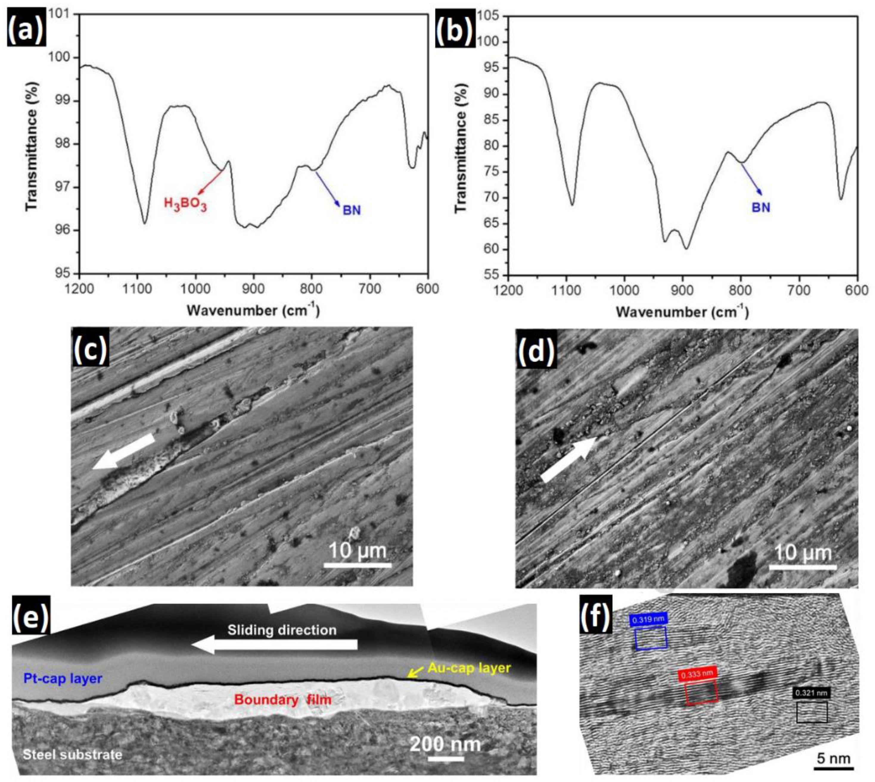
- Gao, C.; Guo, G.; Zhang, G.; Wang, Q.; Wang, H. Formation mechanisms and functionality of boundary films derived from water lubricated polyoxymethylene/hexagonal boron nitride nanocomposites. Mater. Des. 2017, 115, 276–286. [Google Scholar] [CrossRef]
- Garton, A.; Mclean, P.D.; Wiebe, W.; Densley, R.J. Exposure of Cross-linked Epoxy Resins to the Space Environment. J. Appl. Polym. Sci. 1986, 32, 3941–3957. [Google Scholar] [CrossRef]
- Chang, L.; Zhang, Z.; Ye, L.; Friedrich, K. Tribological properties of epoxy nanocomposites III. Characteristics of transfer films. Wear 2007, 262, 699–706. [Google Scholar] [CrossRef]
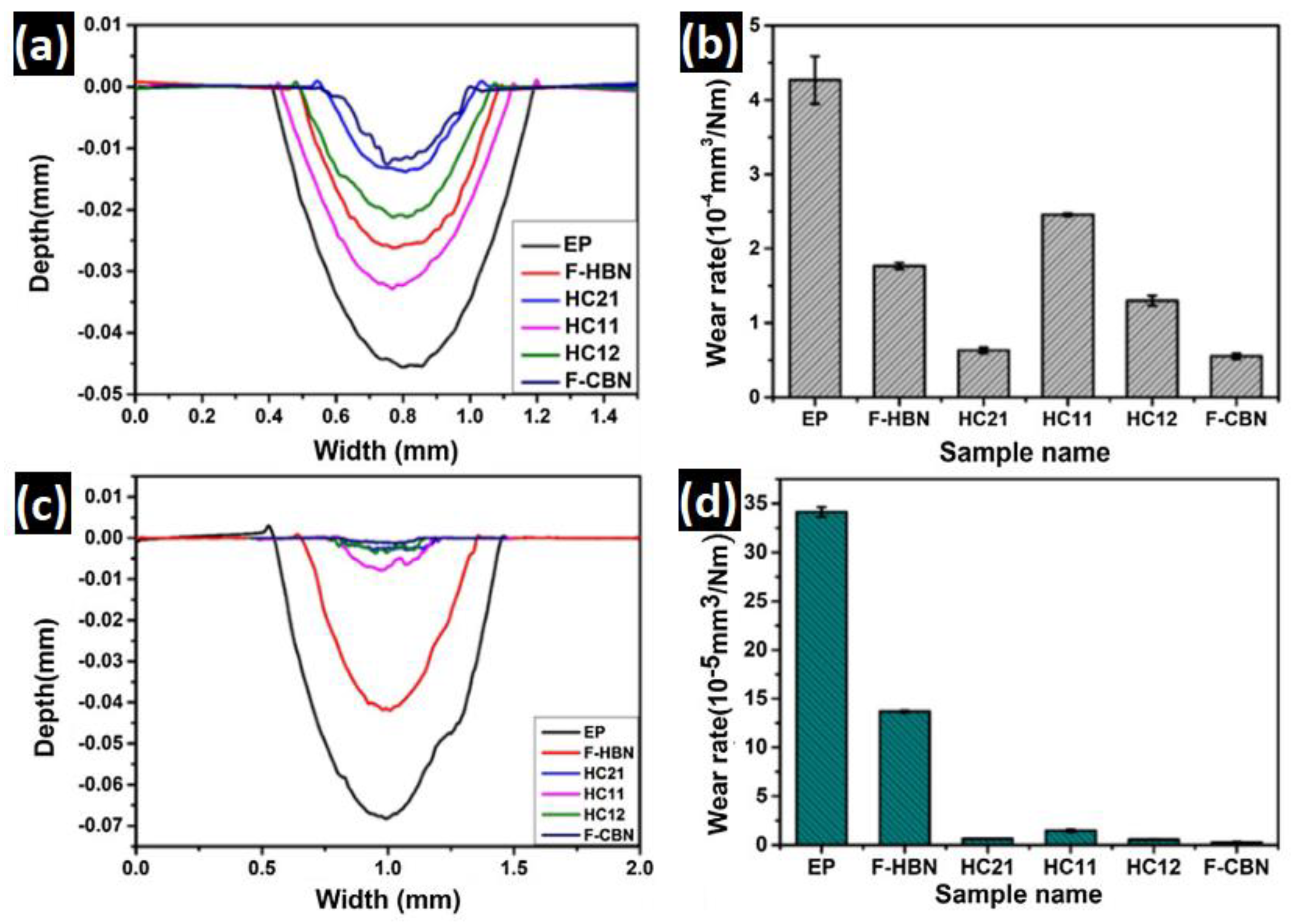
- Yu, J.; Zhao, W.; Wu, Y.; Wang, D.; Feng, R. Tribological properties of epoxy composite coatings reinforced with functionalized C-BN and H-BN nanofillers. Appl. Surf. Sci. 2018, 434, 1311–1320. [Google Scholar] [CrossRef]
- Zhao, W.; Zhao, W.; Huang, Z.; Liu, G.; Wu, B. Tribological performances of epoxy resin composite coatings using hexagonal boron nitride and cubic boron nitride nanoparticles as additives. Chem. Phys. Lett. 2019, 732, 136646. [Google Scholar] [CrossRef]
- Panda, J.N.; Bijwe, J.; Pandey, R.K. Optimization of the amount of short glass fibers for superior wear performance of PAEK Composites. Compos. Part A 2019, 116, 158–168. [Google Scholar] [CrossRef]
- Panda, J.N.; Bijwe, J.; Pandey, R.K. Role of micro and nano-particles of hBN as a secondary solid lubricant for improving tribo-potential of PAEK composite. Tribol. Int. 2019, 130, 400–412. [Google Scholar] [CrossRef]
- Mainzer, B.; Lin, C.; Jemmali, R.; Frieß, M.; Riedel, R.; Koch, D. Characterization and application of a novel low viscosity polysilazane for the manufacture of C- and SiC-fiber reinforced SiCN ceramic matrix composites by PIP process. J. Eur. Ceram. Soc. 2019, 39, 212–221. [Google Scholar] [CrossRef]
- Zhou, W.; Long, L.; Xiao, P.; Jia, C.; Li, Y. Comparison in dielectric and microwave absorption properties of SiC coated carbon fi bers with PyC and BN interphases. Surf. Coat. Technol. 2019, 359, 272–277. [Google Scholar] [CrossRef]
- Nötha, A.; Maier, J.; Schönfeld, K.; Klemm, H. Wet chemical deposition of BN, SiC and Si3N4 interphases on SiC fibers. J. Eur. Ceram. Soc. 2020. [Google Scholar] [CrossRef]
- Tak, W.S.; Uk, J.; Young, H.; Jeong, K.; Sik, W. Coating with boron nitride on SiC fiber using atomic substitution. J. Korean Ceram. Soc. 2020, 57, 200–205. [Google Scholar] [CrossRef]
- Kuang, W.; Zhao, B.; Yang, C.; Ding, W. Effects of h-BN particles on the microstructure and tribological property of self-lubrication CBN abrasive composites. Ceram. Int. 2020, 46, 2457–2464. [Google Scholar] [CrossRef]
- Chen, W.; Zhang, D.; Lv, Z.; Li, H. Self-lubricating mechanisms via the in situ formed tribo-film of sintered ceramics with hBN addition in a high humidity environment. Int. J. Refract. Metals Hard Mater. 2017, 66, 163–173. [Google Scholar] [CrossRef]
- Chen, W.; Wang, K.; Liu, X.; He, N.; Xin, H.; Hao, W. Investigation of the friction and wear characteristics of Si3N4-hBN ceramic composites under marine atmospheric environment. Int. J. Refract Met. Hard Mater. 2019, 81, 345–357. [Google Scholar] [CrossRef]
- Yuan, J.; Zhang, Z.; Yang, M.; Wu, L.; Li, P.; Guo, F.; Men, X.; Liu, W. Coupling hybrid of BN nanosheets and carbon nanotubes to enhance the mechanical and tribological properties of fabric composites. Compos. Part A Appl. Sci. Manuf. 2019, 123, 132–140. [Google Scholar] [CrossRef]
- Liu, F.; Ji, Y.; Sun, Z.; Wang, G.; Bai, Y. Enhancing corrosion resistance of Al-Cu/AZ31 composites synthesized by a laser cladding and FSP hybrid method. Mater. Manuf. Process. 2019, 34, 1458–1466. [Google Scholar] [CrossRef]
- Dodla, S. Micromechanical Analysis for Two-Phase Copper-Silver Composites under Large Deformations. J. Compos. Sci. 2017, 2, 1. [Google Scholar] [CrossRef] [Green Version]
- Fathy, A.; Shehata, F.; Abdelhameed, M.; Elmahdy, M. Compressive and wear resistance of nanometric alumina reinforced copper matrix composites. Mater. Des. 2012, 36, 100–107. [Google Scholar] [CrossRef]
- Elkady, O.A.M.; Abu-Oqail, A.; Ewais, E.M.M.; El-Sheikh, M. Physico-mechanical and tribological properties of Cu/h-BN nanocomposites synthesized by PM route. J. Alloy. Compd. 2015, 625, 309–317. [Google Scholar] [CrossRef]
- Palanivel, R.; Dinaharan, I.; Laubscher, R.F.; Davim, J.P. Influence of boron nitride nanoparticles on microstructure and wear behavior of AA6082/TiB2 hybrid aluminum composites synthesized by friction stir processin. Mater. Des. 2016, 106, 195–204. [Google Scholar] [CrossRef]
- Chi, H.; Jiang, L.; Chen, G.; Kang, P.; Lin, X.; Wu, G. Dry sliding friction and wear behavior of (TiB2 + h − BN)/2024Al composites. Mater. Des. 2015, 87, 960–968. [Google Scholar] [CrossRef]
- Rajan, H.B.M.; Ramabalan, S.; Dinaharan, I.; Vijay, S.J. Effect of TiB2 content and temperature on sliding wear behavior of AA7075/TiB2 in situ aluminum cast composites. Arch. Civ. Mech. Eng. 2014, 14, 72–79. [Google Scholar] [CrossRef]
- Song, Y.; He, G.; Wang, Y.; Chen, Y. Tribological behavior of boron nitride nanoplatelet reinforced Ni3 Al intermetallic matrix composite fabricated by selective laser melting. Mater. Des. 2019, 165, 107579. [Google Scholar] [CrossRef]
- Zhang, Z.; Chen, D.L. Consideration of Orowan strengthening effect in particulate-reinforced metal matrix nanocomposites: A model for predicting their yield strength. Scr. Mater. 2006, 54, 1321–1326. [Google Scholar] [CrossRef]
- Gautam, R.K.S.; Rao, U.S.; Tyagi, R. High temperature tribological properties of Ni-based self-lubricating coatings deposited by atmospheric plasma spray. Surf. Coat. Technol. 2019, 372, 390–398. [Google Scholar] [CrossRef]
- Li, B.; Jia, J.; Gao, Y.; Han, M.; Wang, W. Microstructural and tribological characterization of NiAl matrix self-lubricating composite coatings by atmospheric plasma spraying. Tribol. Int. 2017, 109, 563–570. [Google Scholar] [CrossRef]
- Hammes, G.; Mucelin, K.J.; da Costa Gonçalves, P.; Binder, C.; Binder, R.; Janssen, R.; Klein, A.N.; de Mello, J.D.B. Effect of hexagonal boron nitride and graphite on mechanical and scuffing resistance of self lubricating iron based composite. Wear 2017, 376–377, 1084–1090. [Google Scholar] [CrossRef]
- Kadiyala, A.K.; Bijwe, J. Surface lubrication of graphite fabric reinforced epoxy composites with nano- and micro-sized hexagonal boron nitride. Wear 2013, 301, 802–809. [Google Scholar] [CrossRef]
- De Mello, J.D.B.; Binder, C.; Binder, R.; Klein, A.N. Effect of precursor content and sintering temperature on the scuffing resistance of sintered self lubricating steel. Wear 2011, 271, 1862–1867. [Google Scholar] [CrossRef]
- Kimura, Y.; Wakabayashi, T.; Okada, K.; Wada, T.; Nishikaw, H. Boron nitride as a lubricant additive. Wear 1999, 232, 199–206. [Google Scholar] [CrossRef]
- Abdullah, M.I.H.C.; Abdollah, M.F.B.; Tamaldin, N.; Amiruddin, H.; Nuri, N.R.M. Effect of hexagonal boron nitride nanoparticles as an additive on the extreme pressure properties of engine oil. Ind. Lubr. Tribol. 2016, 68, 441–445. [Google Scholar] [CrossRef]
- Wan, Q.; Jin, Y.; Sun, P.; Ding, Y. Tribological behaviour of a lubricant oil containing boron nitride nanoparticles. Procedia Eng. 2015, 102, 1038–1045. [Google Scholar] [CrossRef] [Green Version]
- Songfeng, E.; Ye, X.; Zhu, Z.; Lu, W.; Li, C. Tuning the structures of boron nitride nanosheets by template synthesis and their application as lubrication additives in water. Appl. Surf. Sci. 2019, 479, 119–127. [Google Scholar] [CrossRef]
- Liu, Y.; Mateti, S.; Li, C.; Liu, X.; Glushenkov, A.M.; Liu, D.; Li, H.; Fabijanic, D.; Chen, Y.I.; Chen, P.Y.I. Synthesis of Composite Nanosheets of Graphene and Boron Nitride and Their Lubrication Application in Oil. Adv. Eng. Mater. 2018, 20, 1700488. [Google Scholar] [CrossRef]
- Ci, X.; Zhao, W.; Luo, J. A sustainable interlayer slip leads to the excellent tribological behaviour of hexagonal boron nitride microsheets. Colloids Surf. A Physicochem. Eng. Asp. 2020, 598, 124859. [Google Scholar] [CrossRef]
- Hu, Y.; Wang, Y.; Zeng, Z.; Zhao, H.; Ge, X.; Wang, K.; Wang, L.; Xue, Q.; Hu, Y.; Wang, Y.; et al. PEGlated Graphene as Nanoadditive for Enhancing the Tribological Properties of Water-based. Carbon N. Y. 2018, 137, 41–48. [Google Scholar] [CrossRef]
- Kumari, S.; Sharma, O.P.; Gusain, R.; Mungse, H.P.; Kukrety, A.; Kumar, N.; Sugimura, H.; Khatri, O.P. Alkyl-Chain-Grafted Hexagonal Boron Nitride Nanoplatelets as Oil-Dispersible Additives for Friction and Wear Reduction. ACS Appl. Mater. Interfaces 2015, 7, 3708–3716. [Google Scholar] [CrossRef]
- Suresha, B.; Shenoy, R.S.; Bhat, R.; Sohan, P.K.; Hemanth, R. Optimization of wear behaviour of boron nitride filled polyaryletherketone composites by Taguchi approach. Mater. Res. Express. 2019, 6. [Google Scholar] [CrossRef]
- Navaneethakrishnan, G.; Karthikeyan, T.; Saravanan, S.; Selvam, V. Influence of boron nitride on morphological, mechanical, thermal and wear characteristics of epoxy nanocomposites. Mater. Res. Innov. 2019, 24, 1–6. [Google Scholar] [CrossRef]
- Li, X.; Gao, Y.; Wei, S.; Yang, Q. Crossmark. Ceram. Int. 2017, 43, 1578–1583. [Google Scholar] [CrossRef]
- Chen, W.; Wang, Z.; Gao, Y.; Li, H.; He, N. Microstructure, mechanical properties and friction/ wear behavior of hot-pressed Si3N4/BN ceramic composites. Ceram. Silik. 2019, 63, 1–10. [Google Scholar] [CrossRef] [Green Version]
- Zhao, Y.; Feng, K.; Yao, C.; Nie, P.; Huang, J.; Li, Z. Microstructure and tribological properties of laser cladded self-lubricating nickel-base composite coatings containing nano-Cu and h-BN solid lubricants. Surf. Coat. Technol. 2019, 359, 485–494. [Google Scholar] [CrossRef]
- Gopinath, S.; Prince, M.; Raghav, G.R. Enhancing the mechanical, wear and corrosion behaviour of stir casted aluminium 6061 hybrid composites through the incorporation of boron nitride and aluminium oxide particles. Mater. Res. Express. 2020, 7. [Google Scholar] [CrossRef]
- Chen, Z.; Yan, H.; Zhang, P.; Yu, Z.; Lu, Q.; Guo, J. Microstructural evolution and wear behaviors of laser-clad Stellite 6/NbC/h-BN self-lubricating coatings. Surf. Coatings Technol. 2019, 372, 218–228. [Google Scholar] [CrossRef]


| Matrix | Filler & Content | Procedure | Outcome | Other Features | Ref. |
|---|---|---|---|---|---|
| Epoxy | Hollow h-BN microbeads (65.6 vol.%) | Salt-template, Infiltration | 17.61 W m−1·k−1 (↑ 88 times) | Improved Thermal Stability, Lower Dielectric constant | [58] |
| Epoxy | BNNSs (15 vol.%) | Bidirectional Freeze-drying, Infiltration | 6.07 W m−1·k−1 (↑ 32 times) | Improved Thermal Stability | [52] |
| Epoxy | MWCNT (2 wt.%) – BNNSs (23 wt.%) | CVD, Exfoliation, Infiltration | 1.50 W m−1·k−1 (↑ 6.15 times) | Enhanced Tensile Strength, Lower Dielectric constant | [68] |
| Epoxy | Expanded Graphite (2.5 wt.%)–h-BN platelets (70 wt.%) | Mixing, curing | 2.08 W m−1·k−1 (↑2.08 times) | - | [27] |
| Polyimide (PI) | Functional h-BN (50 wt.%) | Ball milling, freeze-drying, curing | 9.8 W m−1·k−1 (↑ ~32 times) | Hydrophobicity, Enhanced Thermal Stability | [54] |
| Polyimide (PI) | Functionalized h-BN (30 wt.%) | In situ polymerization, electrospinning, hot press | 0.71 W m−1·k−1 (↑ 4.73 times) | Enhanced Thermal Stability, Higher Glass Transition Temperature | [26] |
| Polyamide (PI) | h-BN platelets (20 wt.%) | Plasma-assisted mechanochemistry | 3.68 W m−1·k−1 (↑ 14.72 times) | Enhanced Young’s Modulus | [85] |
| Phosphorus-free bimaleimide | h-BN skeleton (12.53 wt.%) | Frame molding, curing | 1.53 W m−1·k−1 (↑ 9.40 times) | Flame-retardancy | [61] |
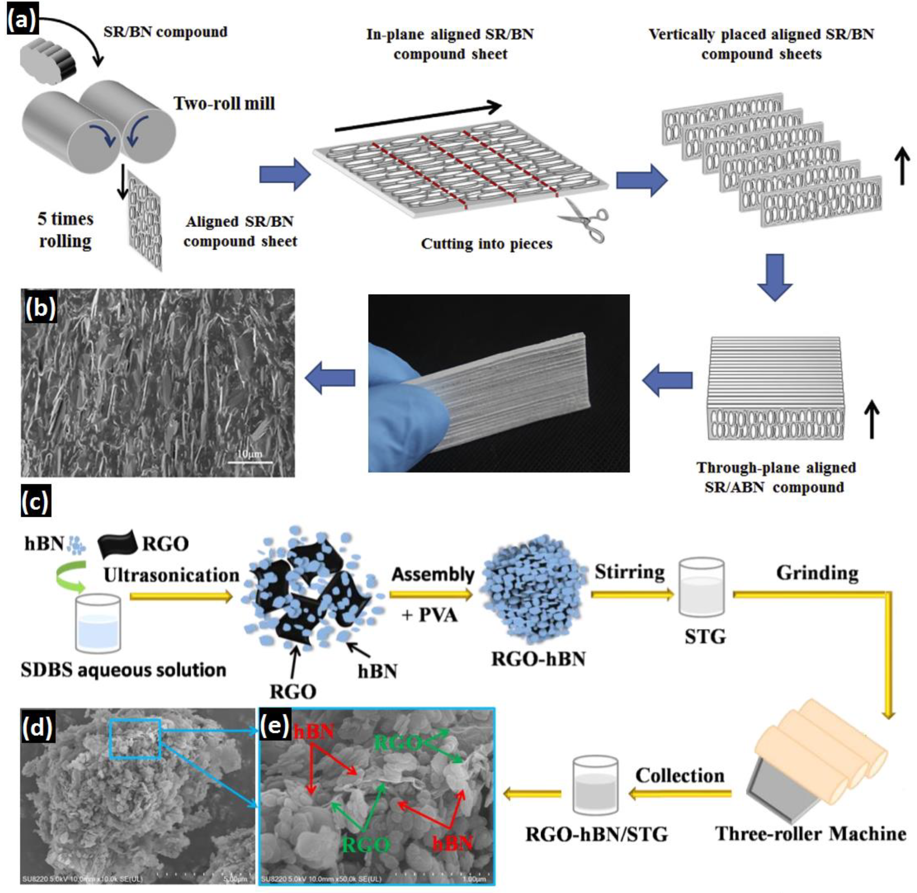
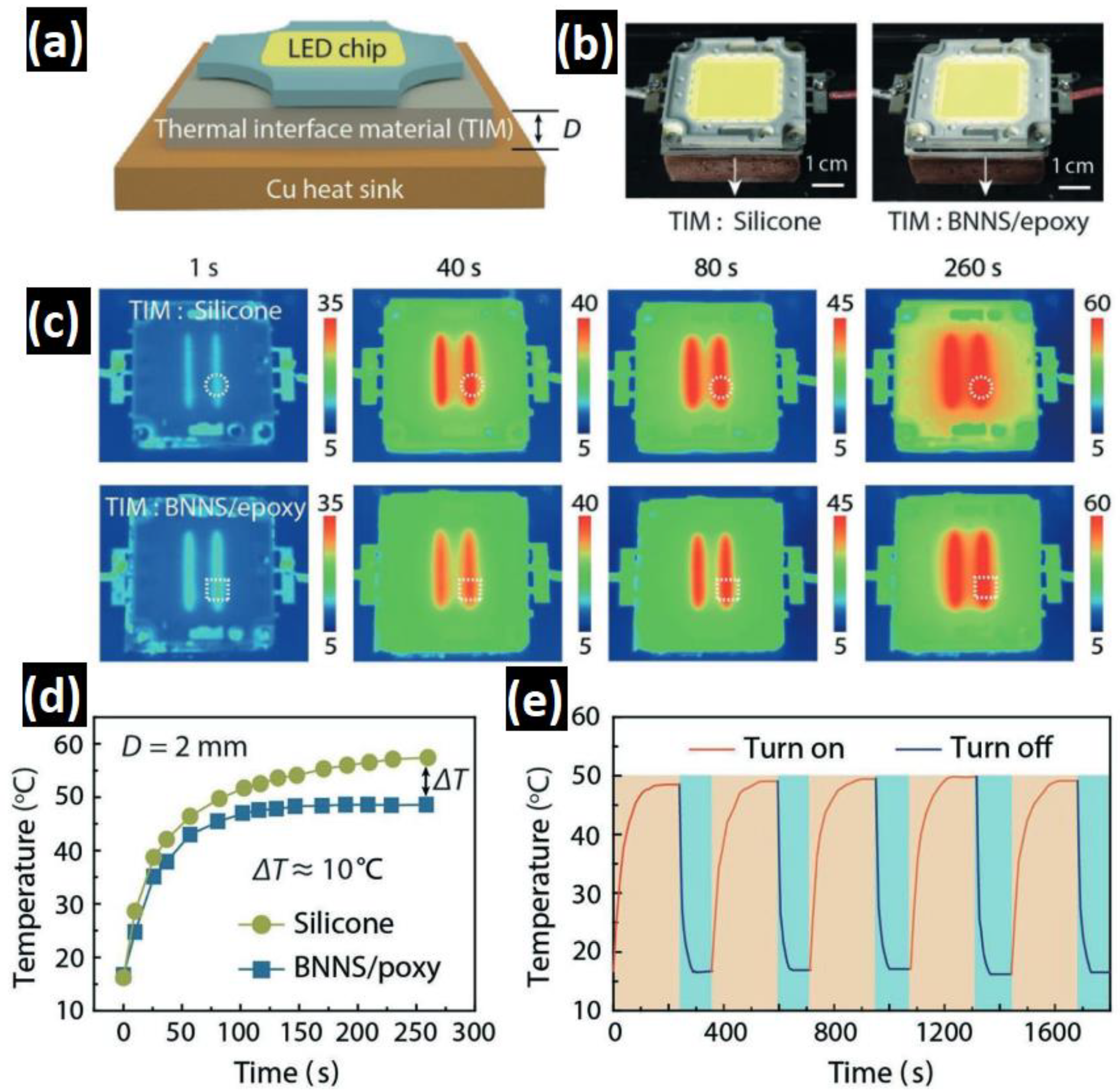
| Silicone rubber | Vertically aligned h-BN (39.8 vol.%) | Rolling, curing | 5.40 W m−1·k−1 (↑ ~33 times) | Potential for TIMS | [63] |
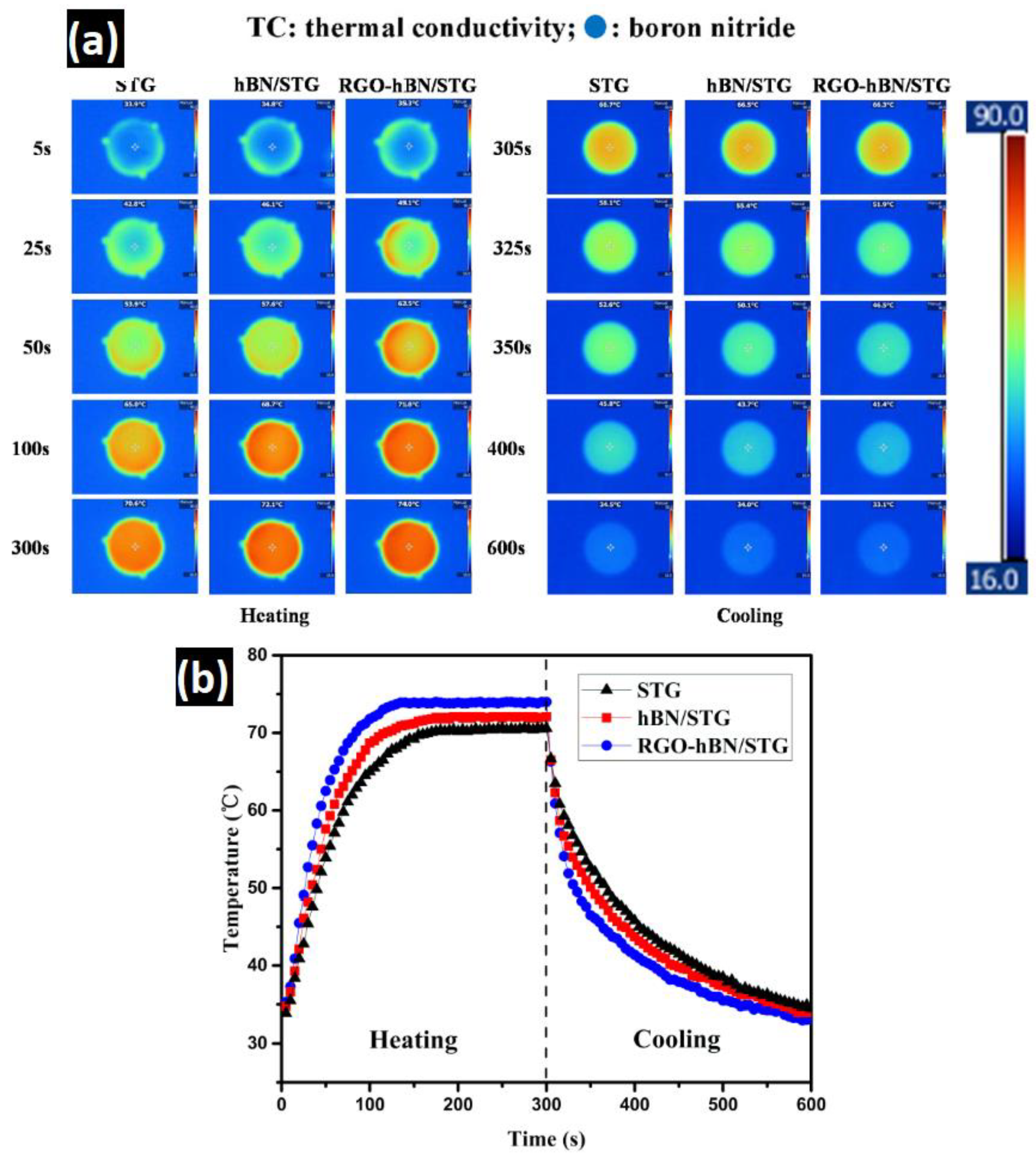
| Silicon thermal grease (STG) | RGO–BNNS (12 wt.%) | Exfoliation, self-assembly, rolling | 3.38 W m−1·k−1 (↑ ~1.8 times) | - | [64] |
| Natural rubber | Functionalized h-BN platelets (30 vol.%) | Mixing, rolling | 0.39 W m−1·k−1 (↑ ~4 times) | Lower Dielectric Constant | [48] |
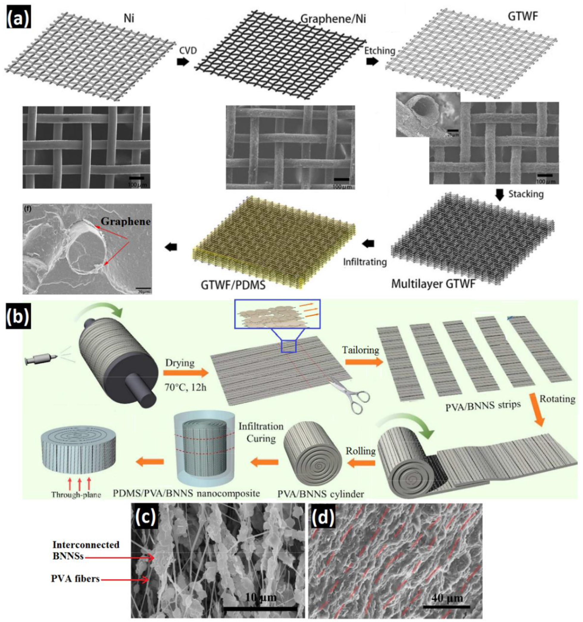
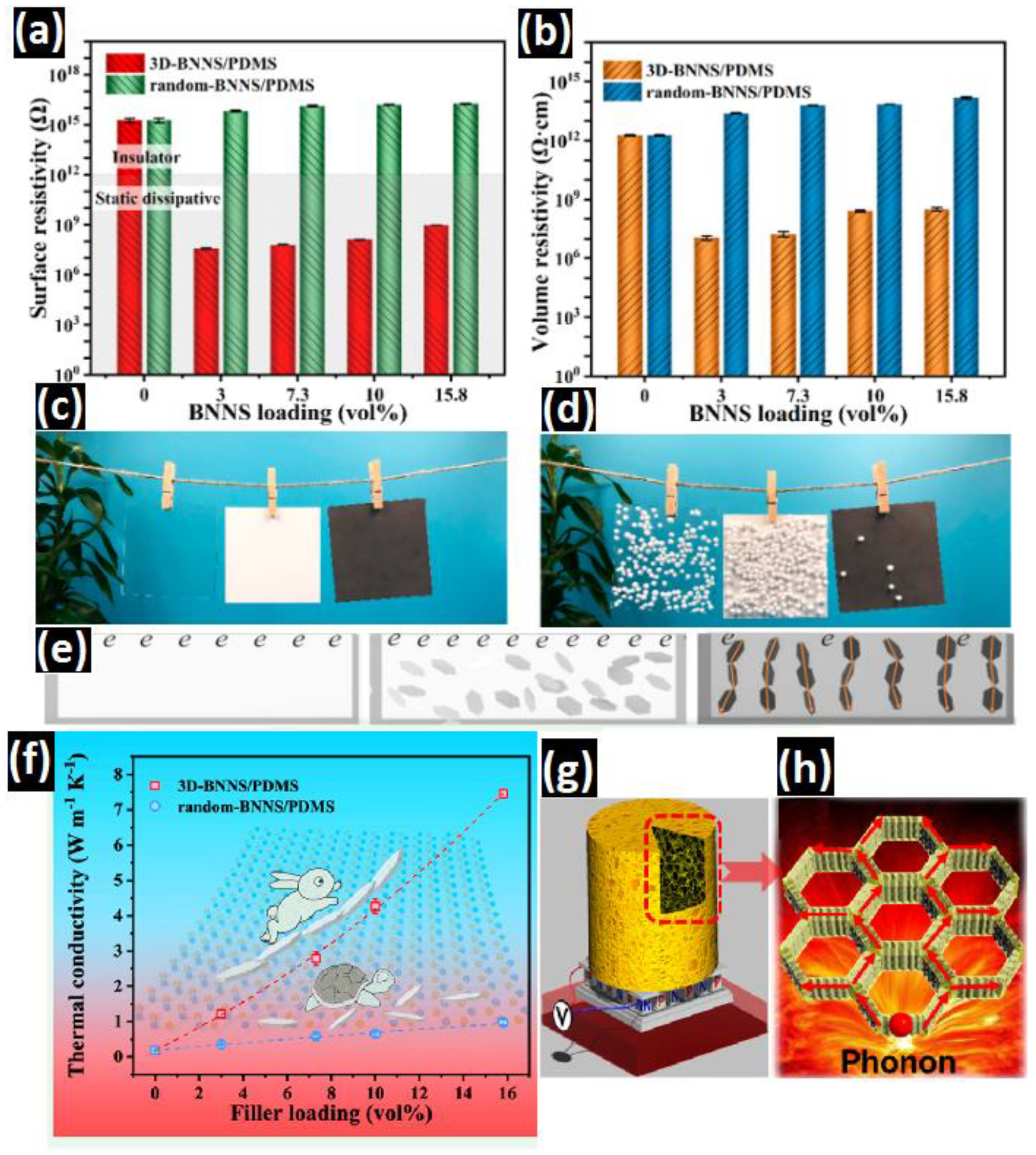
| Polydimethylsiloxane (PDMS) | BNNSs (15.8 vol.%) | Freeze-drying, carbonization | 7.46 W m−1·k−1 (↑ 39 times) | Antistatic Behavior | [53] |
| Polydimethylsiloxane (PDMS) | Graphite tube woven fabric (4.2 wt.%)–h-BN sheets (14 wt.%) | CVD, infiltration | 3.10 W m−1·k−1 (↑ 2.52 times) | - | [33] |
| Poly(m-phenylene isophthalamide) (PMIA) | Nano h-BN (30 wt.%) | Casting technique | 0.94 W m−1·k−1 (↑ ~4 times) | Low Dielectric Constant, Ideal Dielectric Loss | [47] |
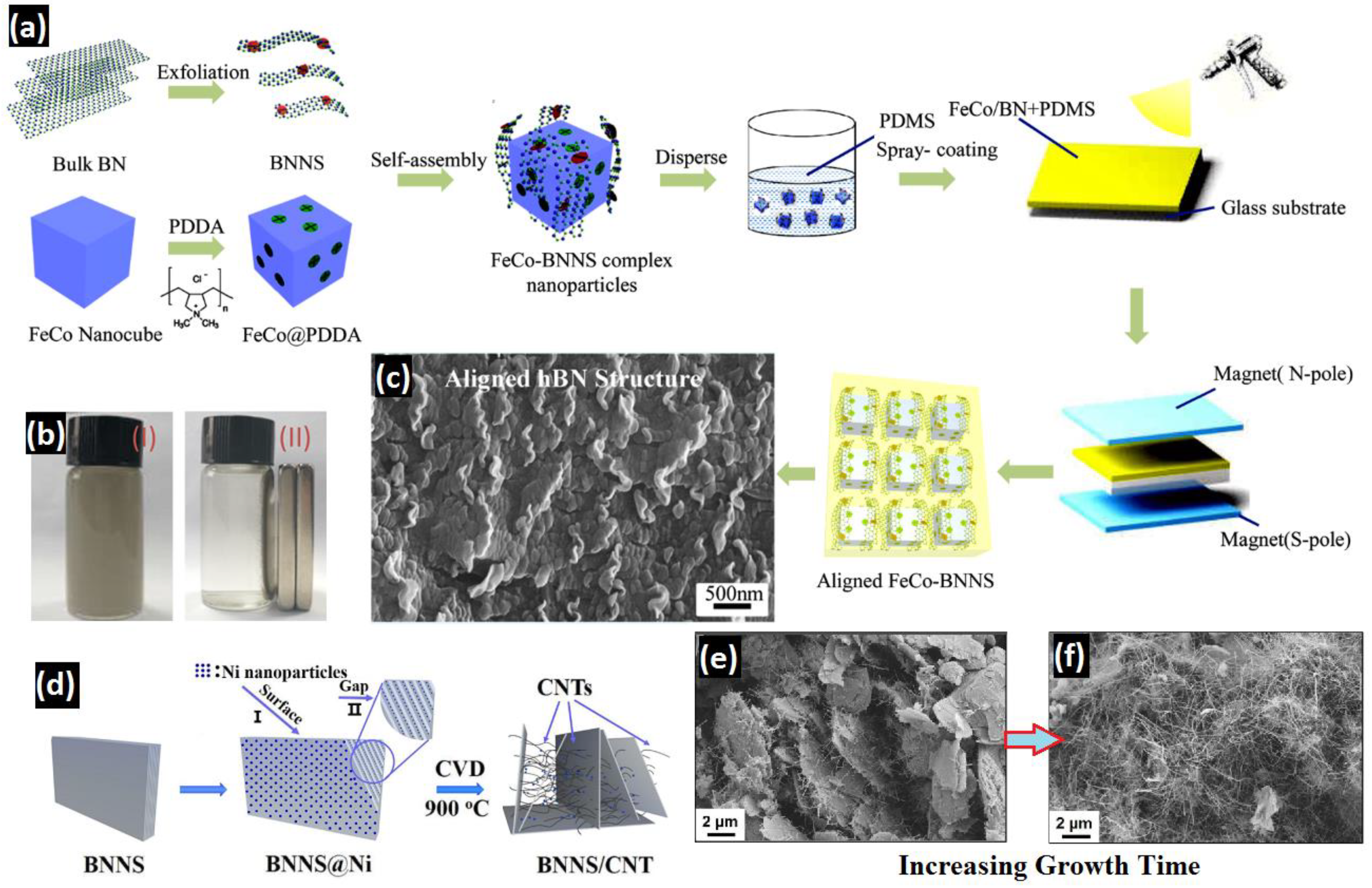
| Poly(diallyldimethylammonium chloride) (PDDA) | BNNSs (50 wt.%)–FeCo nanocubes (30 wt.%) | Exfoliation, self-assembly, mixing | 2.25 W m−1·k−1 (↑ ~20.5 times) | Superb Flexibility | [62] |
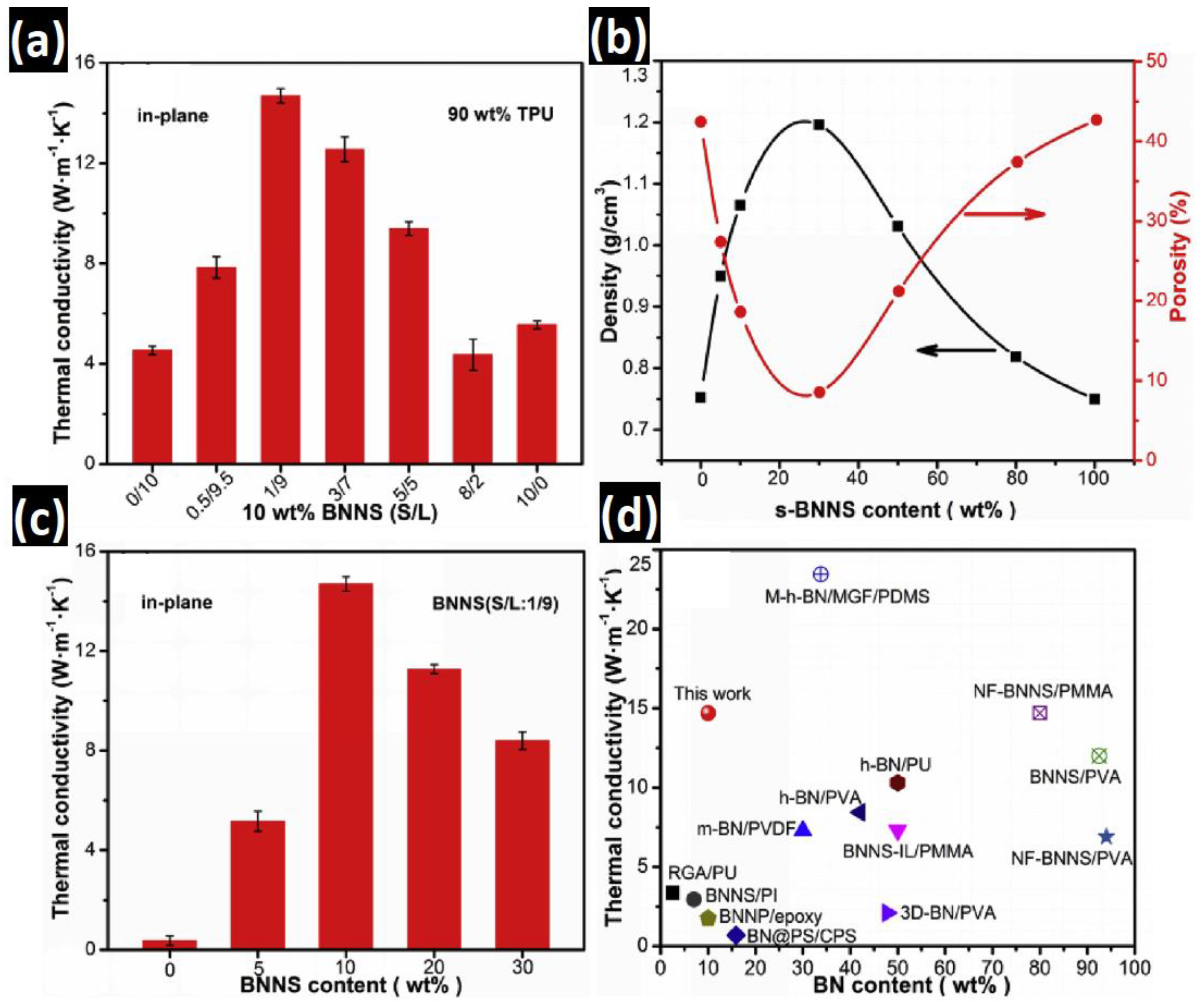
| Thermoplastic polyurethane (TPU) | BNNSs (10 wt.%) | Ultrasonic exfoliation, self-assembly | 14.7 W m−1·k−1 (↑ 29.4 times) | - | [59] |
| Polyethylene glycol (PEG) | BNNS (1.9 vol.%)–doped cellulose nanofiber (2.5 wt.%) | Freeze-drying, layer-by-layer assembly, vacuum impregnation | 0.40 W m−1·k−1 (↑ ~0.5 times) | Excellent Shape Stability against Pressure, Tension, and Bending | [84] |
© 2020 by the authors. Licensee MDPI, Basel, Switzerland. This article is an open access article distributed under the terms and conditions of the Creative Commons Attribution (CC BY) license (http://creativecommons.org/licenses/by/4.0/).
Share and Cite
Khalaj, M.; Zarabi Golkhatmi, S.; Alem, S.A.A.; Baghchesaraee, K.; Hasanzadeh Azar, M.; Angizi, S. Recent Progress in the Study of Thermal Properties and Tribological Behaviors of Hexagonal Boron Nitride-Reinforced Composites. J. Compos. Sci. 2020, 4, 116. https://0-doi-org.brum.beds.ac.uk/10.3390/jcs4030116
Khalaj M, Zarabi Golkhatmi S, Alem SAA, Baghchesaraee K, Hasanzadeh Azar M, Angizi S. Recent Progress in the Study of Thermal Properties and Tribological Behaviors of Hexagonal Boron Nitride-Reinforced Composites. Journal of Composites Science. 2020; 4(3):116. https://0-doi-org.brum.beds.ac.uk/10.3390/jcs4030116
Chicago/Turabian StyleKhalaj, Maryam, Sanaz Zarabi Golkhatmi, Sayed Ali Ahmad Alem, Kahila Baghchesaraee, Mahdi Hasanzadeh Azar, and Shayan Angizi. 2020. "Recent Progress in the Study of Thermal Properties and Tribological Behaviors of Hexagonal Boron Nitride-Reinforced Composites" Journal of Composites Science 4, no. 3: 116. https://0-doi-org.brum.beds.ac.uk/10.3390/jcs4030116