A Nonlinear Analysis Interpretation of Off-Axis Test Results in Metal Matrix Composites


1
Research Applications, Inc., 11772 Sorrento Valley Road, Suite 260, San Diego, CA 92121, USA
2
Structural Analytics Inc., PO Box 131447, Carlsbad, CA 92013, USA
3
Pratt & Whitney, 400 Main Street, East Hartford, CT 06108, USA
*
Author to whom correspondence should be addressed.
J. Compos. Sci. 2020, 4(3), 127; https://0-doi-org.brum.beds.ac.uk/10.3390/jcs4030127
Submission received: 26 July 2020
/
Revised: 27 August 2020
/
Accepted: 28 August 2020
/
Published: 31 August 2020
(This article belongs to the Special Issue Metal Composites)
Abstract
:A unit-cell based micromechanics approach is used to perform nonlinear finite element analyses of off-axis tensile tests on an SCS-6/Ti-6Al-4V composite. The results are used in predicting the global deformation response of the composite that includes the effect of fiber-matrix interface damage. The predictions are compared with laboratory test data of uniaxial off-axis specimens. Based on the comparison, it is found that the procedure effectively predicts global composite response with reasonable accuracy under a general multiaxial stress state.
1. Introduction
Titanium-based metal matrix composites (MMCs) offer excellent potential for high-temperature applications that require a combination of high strength, stiffness and toughness [1,2]. Advances in the processing of this class of materials have made them technologically viable for use in various high-temperature structural applications in the aerospace, automotive and thermal management industries [3,4,5,6]. In many of these applications, components often experience multiaxial stresses.
The off-axis tensile (OAT) test is considered as a viable method for characterizing the global, multiaxial stress-strain response of composites in the nonlinear deformation range [7,8,9,10,11]. Additionally, attempts are being made to formulate theoretical models that can be used in nonlinear stress analysis of continuous fiber and particulate MMCs under multiaxial stress states [12,13,14,15,16,17,18,19,20,21,22,23,24,25,26]. In the unit-cell and representative volume element (RVE) approaches [16,17,18,19,20,21,22,23], the composite is assumed to consist of a repeating array of units, each consisting of either a single fiber or an array of fibers embedded in a matrix material. Appropriate boundary conditions are enforced on the boundaries of the unit-cell model to represent the periodicity conditions. When applied to continuous-fiber MMCs, they have been shown to capture global nonlinear structural behavior [17,18,19,20]. Micromechanics-based continuum models that include plasticity and damage [14,15,24] have been shown to capture failure modes and values of failure stress at the global level. Capturing finer details of local deformation and stress states requires the use of multiscale models that integrate different analytical models, each representing a particular microstructural scale of the material [25]. These models provide a level of detail for the stress and strain fields at different structural scales in the material along with the evolution and growth of damage at these levels. Particulate composites have also been modeled using finite-element analysis by either mapping three-dimensional images of the microstructure to capture details of particle shape and distribution [26] or by randomly generating the particle size and distribution [27]. While this approach yields finer details of material behavior at the microstructural level as compared to other models, they are computationally inefficient for the analysis of large structures.
The general approach in applying the above-discussed models to analyze the structural response of MMCs is to implement them as material constitute laws. Limited application of analytical models to the stress analysis of MMCs subjected to off-axis and multiaxial loading also exist in literature. In the present work, we outline a modeling framework that uses readily-available commercial finite-element software with its built-in constitutive models to capture the deformation of off-axis continuous fiber MMCs. The procedure can be useful at the laboratory-level to characterize material structural behavior. It can also be useful in providing benchmark numerical solutions that can potentially benefit the development of more advanced analytical models and for their verification.
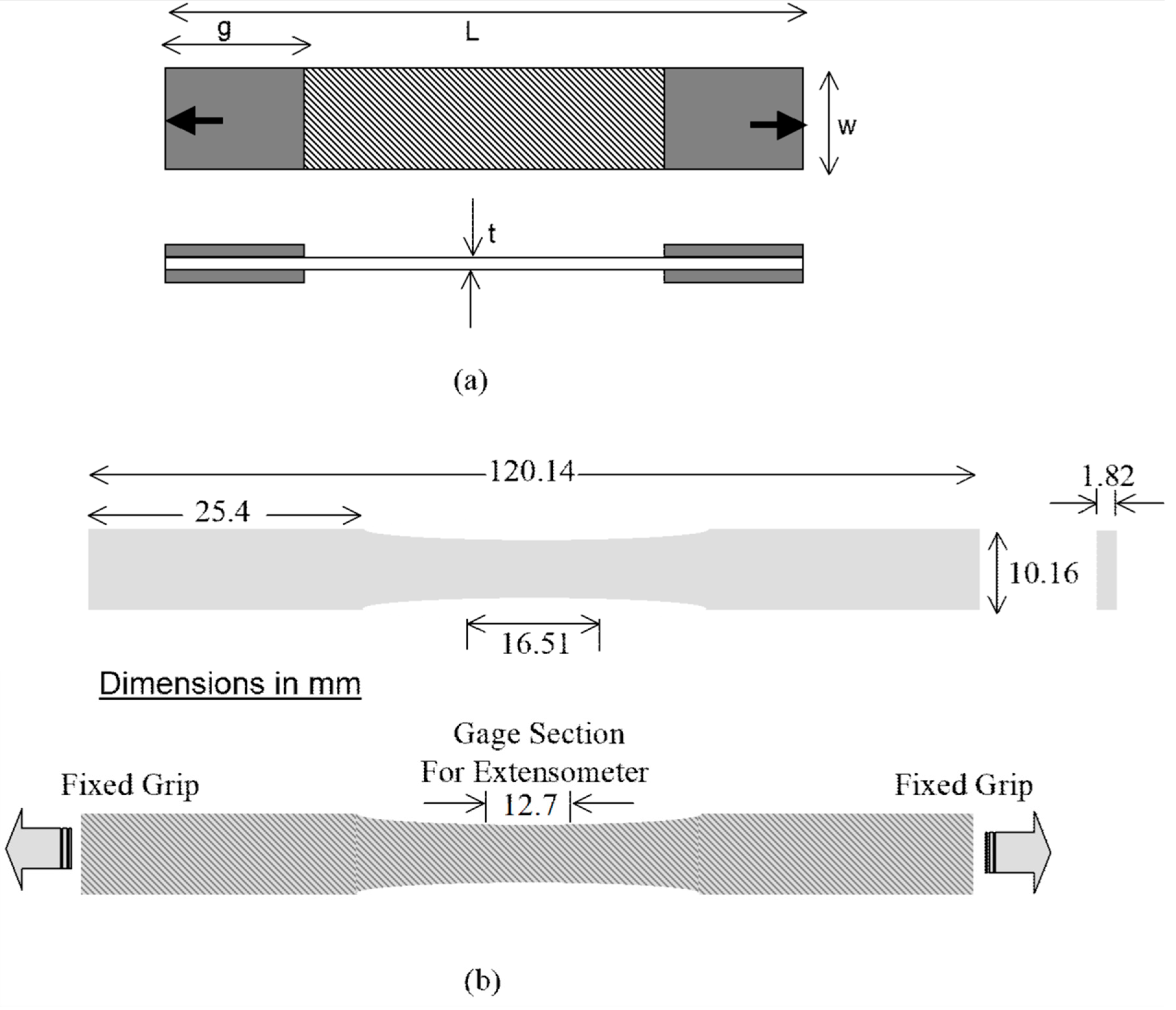
In this study, OAT specimens are used to characterize the nonlinear stress-strain behavior of a composite of SCS-6 silicon carbide fibers in an alloy of titanium, aluminum and vanadium (Ti-6Al-4V). Figure 1 shows the dimensions of the OAT test specimen configurations used for testing the unidirectional MMC. The angle between the fiber-length and load-application directions is θ. Except for θ = 0° and 90°, the OAT specimen experiences a multiaxial stress state. Table 1 shows the relative magnitude of , and stress components assuming a (global) state of plane stress. It has been found that, for judiciously selected specimen dimensions, the stress state in the gauge section of OAT specimens is sufficiently uniform [28].
The uniformity of stress state enables consideration of a ‘unit-cell’ based micromechanics analysis approach for predicting nonlinear deformation response of an OAT specimen. In such an approach, the unit-cell consists of a single fiber surrounded by a matrix region. The composite is assumed to be the assemblage of a very large number of unit-cells. The deformation and damage within a unit-cell can be related to the global deformation behavior of a composite under a uniform state of stress. The unit-cell approach has been successfully used for predicting nonlinear axial (θ = 0°) and transverse (θ = 90°) behavior of MMCs (for example, see [17]). As discussed in [17], for other off-axis angles, nonlinear micromechanics analysis becomes considerably more complicated. In the present study, the approach outlined in [28] is extended to include micromechanical damage such as fiber-matrix debonding and sliding, and elastic-plastic analysis results for θ = 15°, 30° and 45° are presented. The predicted stress-strain response of the composite is compared with laboratory test data on SCS-6/Ti-6Al-4V eight-ply composite.
2. Approach
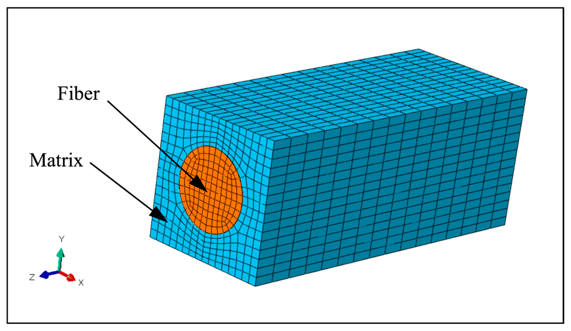
Figure 2 shows the three-dimensional finite element model of the unit-cell configuration considered in the present work. It consists of 11,657 nodes and 2560 quadratic hexahedral elements representing a single circular fiber surrounded by a rectangular block of matrix material. All finite element analyses were performed using the ABAQUS general-purpose software [29]. Both the fiber and the matrix materials were assumed to be isotropic. The fiber material was assumed to be linear-elastic. The matrix material was modeled as being elastic-plastic using the *PLASTIC option with isotropic hardening in ABAQUS (version 6.11, ABAQUS Inc., Palo Alto, CA, USA). A weak fiber-matrix bond was assumed. Surface contact elements were used to model the fiber-matrix interface, which allowed sliding and separation but not the overlapping of surfaces. In relation to the off-axis test specimen, the unit-cell was considered representative of the material well within the uniformly stressed gauge section. Thus, the stresses on the surfaces of the unit-cell were those experienced by a point within the gauge section of the specimen due to the applied load. Additionally, the fiber and the matrix materials in the unit-cell were under internal stress induced by the consolidation process used in the fabrication of the composite. Before stress analysis of the unit-cell could be performed, both the surface and the internal stresses acting on the unit-cell needed to be determined. The procedures adopted in the present work are described below.
2.1. Determination of Internal State of Stress
The determination of internal stresses within the unit-cell is relatively straightforward if the temperature-dependent stress-strain curves and coefficients of thermal expansion (CTEs) of the matrix and the fiber materials are known. As discussed in detail by Kroupa [30], one starts by assuming that at the highest temperature (Tp) during consolidation, the fiber and the matrix are stress-free. The unit-cell is then subjected to incremental reductions in temperature (T) while all external surfaces of the unit-cell are constrained against distortion. This can be accomplished by using the so-called multi-point constraints. When applied to the displacement component normal to any of the surfaces of the unit-cell, all node points on the surface displace by an equal amount in that direction. Because there is no external force applied, the net force acting normal to any surface is zero.
In previous studies [30], it has been found that the residual internal stress computed using a single step cool-down from Tp to a reference temperature (Tr) is approximately the same as that computed by the incremental procedure described above. Of course, the main advantage of a single step cool-down is that values of relevant constituent properties are needed corresponding to the reference temperature only. In addition, the analysis is linear. In the present study, a single step cool-down method was used.
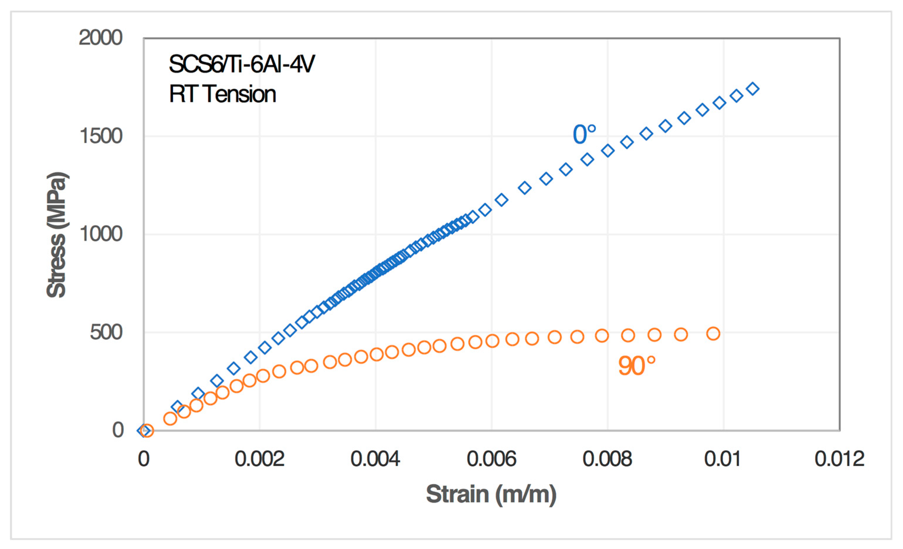
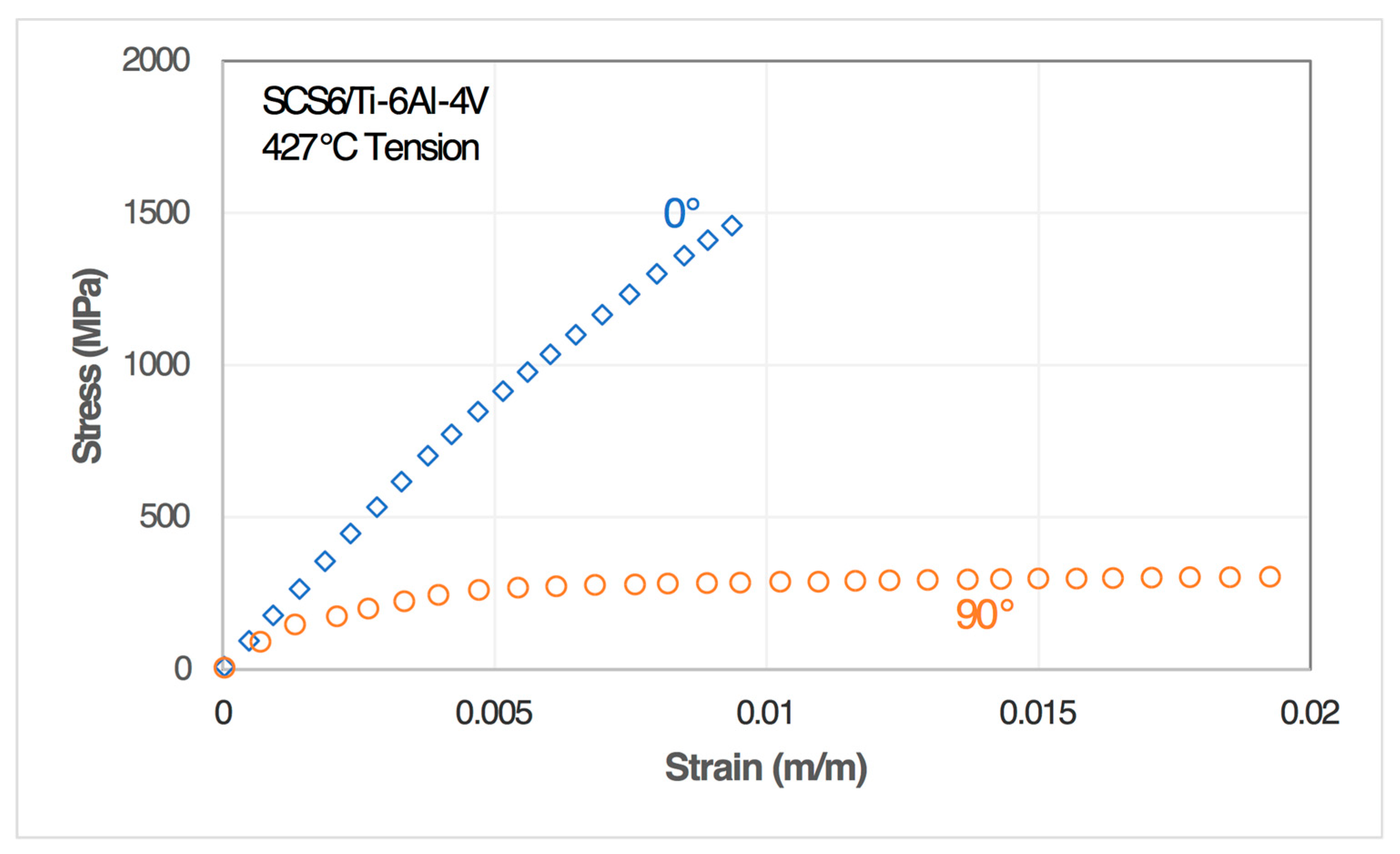
The material system considered in the present work was SCS-6/Ti-6Al-4V eight-ply unidirectional ([0]8) composite. Off-axis tensile testing was conducted on this composite by following the ASTM D3039 method [31]. Configurations of the specimens used in uniaxial off-axis tests are shown in Figure 1a,b. The relevant mechanical properties and CTE values for the Ti-6Al-4V matrix and the SCS-6 fiber are given in Table 2 and Figure 3. Figure 4 and Figure 5 show the stress-strain curves of the composite for 0° and 90° loadings at room temperature (RT) and 427 °C, respectively. Using the 0° curve at RT and the simple rule-of-mixtures for tensile modulus, the effective value of the fiber volume fraction (Vf) is found to be approximately 0.27. The unit-cell shown in Figure 2 corresponds to Vf = 0.27.
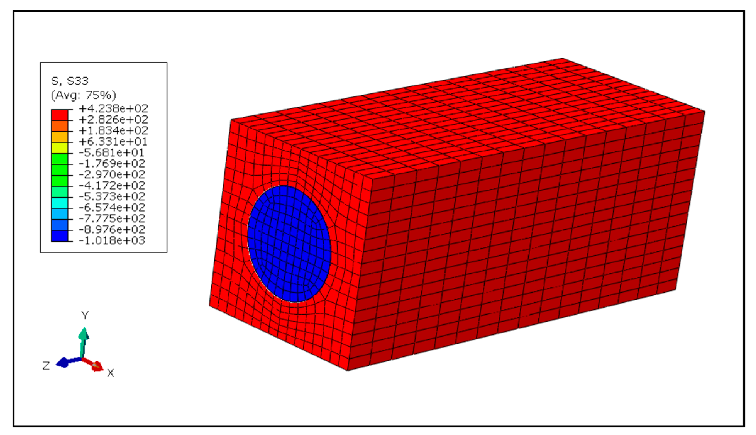
Using Tp = 815 °C [30], the computed axial-direction residual stress state in the composite at RT (Tr = 23 °C) is shown in Figure 6. It can be seen that the fiber was in compression, while the residual stress state of the matrix was tensile in nature. The same procedure was used to compute residual stresses in the unit-cell at temperature Tr = 427 °C. These residual stress states were used as part of the initial conditions in the subsequent analyses of off-axis loading cases. For eventual comparison with test data, the strain state at reference temperature was defined to be the reference strain state.
2.2. Determination of Boundary Conditions
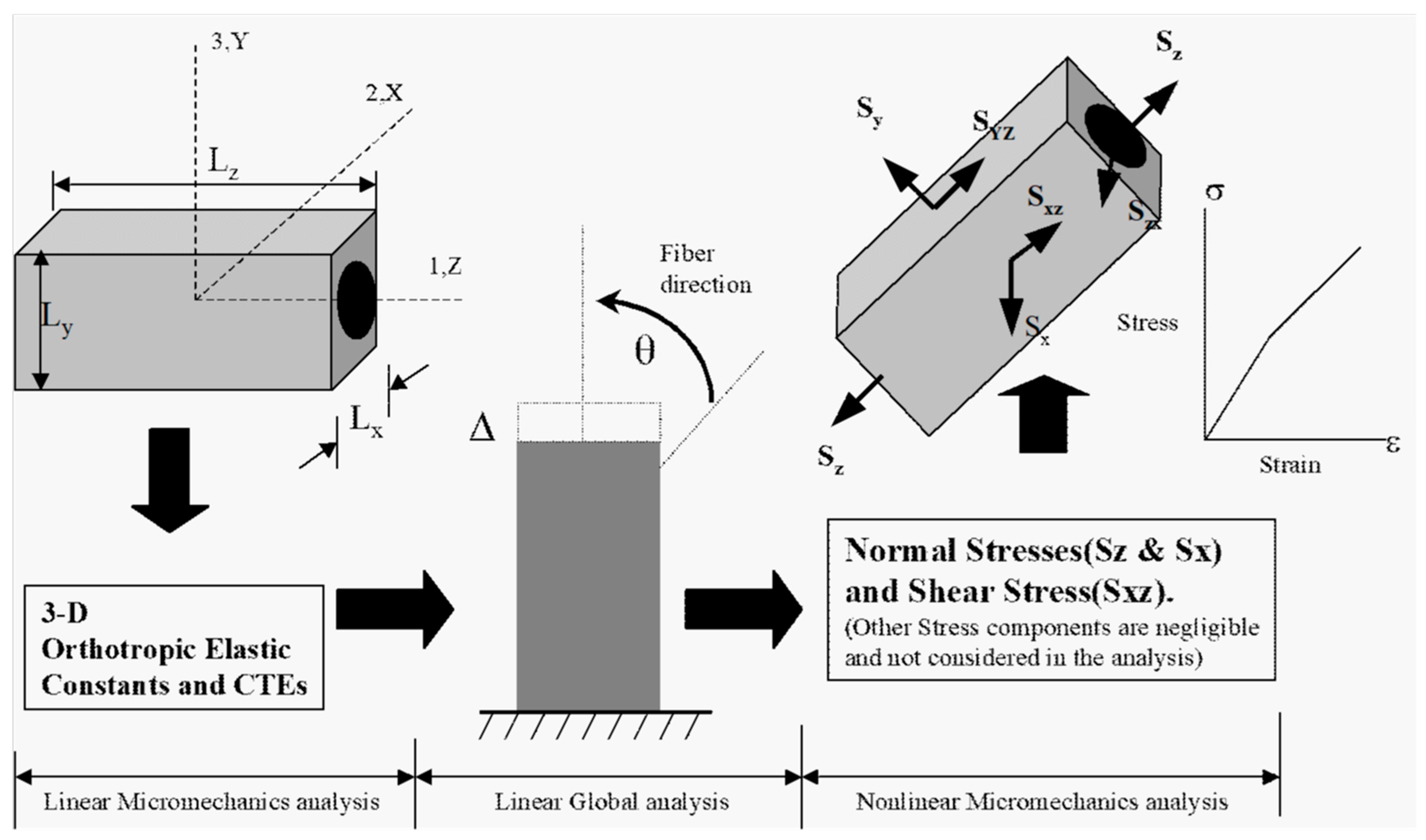
In addition to the initial internal stress state, subsequent nonlinear analyses require the boundary conditions on the unit-cell to be prescribed. For a general three-dimensional case of off-axis loading, the determination of these boundary conditions requires a sequence of global (macromechanics) and local (micromechanics) linear analyses, as shown in Figure 7.
First, linear micromechanics analyses were performed using the unit-cell model of Figure 2 to obtain orthotropic elastic constants and CTE values for the composite at 23 °C and 427 °C. This required a number of analyses, each under a different set of boundary conditions representing purely normal ( and ) and purely shear ( and ) stress states. For example, to determine the fiber direction properties, the face normal to the 1-axis at L was subjected to a uniform x-direction displacement (u1), and the opposite face at x = 0 was prescribed to have u1 = 0.0. The average stress in the fiber direction () was then calculated to be the net force in direction-1 (F1) divided by the area (d × d) of the cell cross-section. The average strain in direction-1 () was defined to be u1⁄L. Thus, the composite modulus in the fiber direction, .
Averaging of stress and strain components across the unit-cell dimensions was necessary in order to interpret micromechanics solutions in terms of global composite properties. In effect, the assumption was that the variation of each displacement component across the unit-cell dimension was linear and, therefore, each strain and stress component was constant. A difficulty was faced in the estimation of shear modulus values because the effect of the free edges caused the shear strains within the unit-cell to be non-uniform. However, the strains were uniform over a smaller region within the unit-cell. Therefore, averaging was done across the dimensions of this sub-cell rather than the whole unit-cell.
Table 3 is a summary of the results of the linear micromechanics analyses. Next, the orthotropic elastic constants and the CTE values were provided as part of the input to linear global analyses of off-axis test specimens with θ = 15°, 30° and 45°. The purpose was to determine the three-dimensional stress state in the interior of a gauge section, which would provide the boundary conditions for the subsequent nonlinear micromechanics analyses.
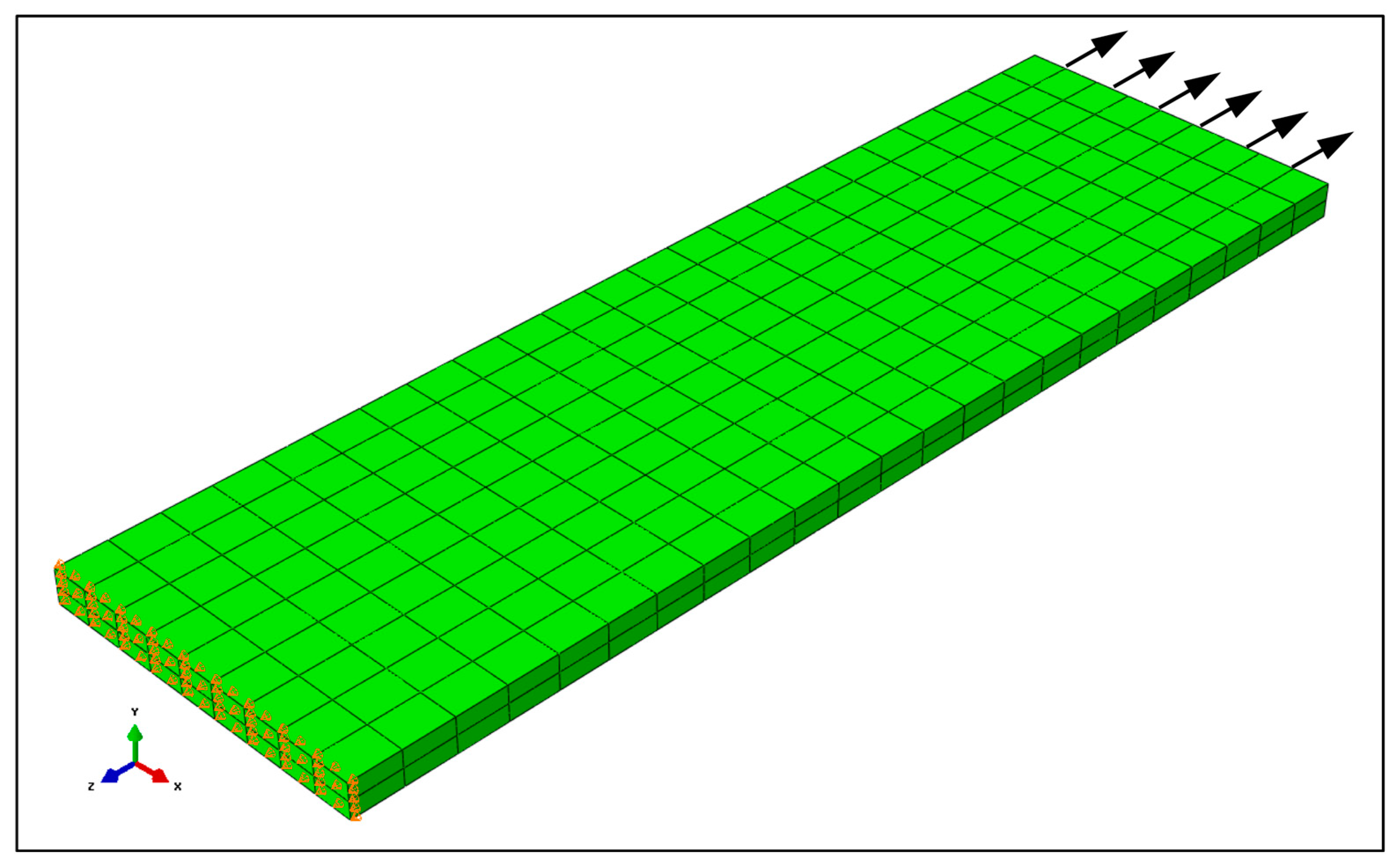
The finite element mesh of a rectangular test specimen and the boundary conditions used in the linear, three-dimensional global analyses are shown in Figure 8. Direction-dependent properties were used in this analysis with 1-direction of the material coordinate system representing the zero-degree case. By transforming the material coordinate system with respect to the global coordinate system, different off-axis cases were simulated.
The results of these analyses showed that, except in relatively narrow regions close to edges of the specimen, the three-dimensional stress state was uniform. The results are summarized in Table 4. The values given in Table 4 correspond to an applied stress of 1 MPa. Since this analysis was linear, stress components which were applied as boundary conditions could be scaled linearly for different values of applied loads. These values of stress components provided the traction boundary conditions for subsequent nonlinear micromechanics analyses.
3. Results and Discussion
Under off-axis loading, MMCs are prone to fiber-matrix interface damage. Interface damage can be in the form of separation caused by stresses normal to the fiber direction or relative sliding between a fiber and the surrounding matrix caused by shear stress. In titanium matrix composites with ceramic fibers, the interfacial bond strength is negligibly small compared to the strengths of the constituents. It has been found [32] that debonding between the fiber and the matrix occurs when the normal tensile stress across the interface exceeds the compressive residual stress (R22) induced by the consolidation process. A criterion for the onset of sliding damage is not as definitively known. It seems likely that the onset of sliding damage is, to some extent, governed by friction between the fiber and the matrix. However, there are no methods for unambiguously establishing the value of the coefficient of friction.
Nonlinear analyses were performed using the same unit-cell configuration shown in Figure 2. Double nodes were used on the curved surface of the fiber. Surface contact elements were used for possible debonding and sliding. These elements allowed separation and relative sliding of the mating surfaces, but prevented inter-penetration. The fiber and matrix material properties were assigned according to Table 2 and Figure 3. As discussed earlier, the initial stress in the unit-cell for each analysis was the residual stress induced by the composite consolidation process. Each analysis was done by applying traction boundary conditions in accordance with Table 4. Additionally, appropriate displacement boundary conditions were applied to prevent rigid body motion.
Initial heuristic analyses of the 15° off-axis case were performed using several different values of the coefficient of friction (µ). As evident from Table 4, this case has the highest ratio and is, therefore, most prone to interfacial sliding damage. It was found that insurmountable convergence problems occurred when the condition for sliding damage (]) was met. Additionally, the solution was extremely sensitive to the choice of µ. Since the value of µ had to be assigned rather arbitrarily, and because of the convergence problems, the analyses were performed without consideration of sliding damage.
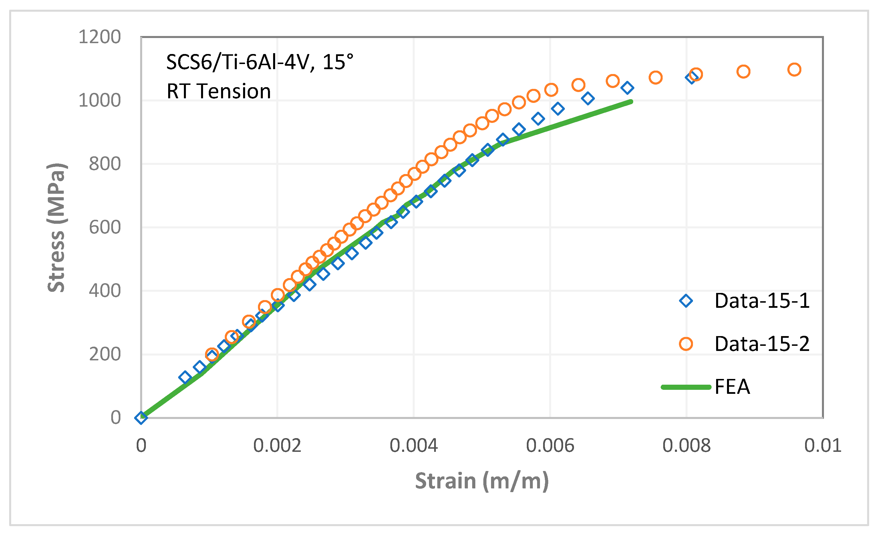
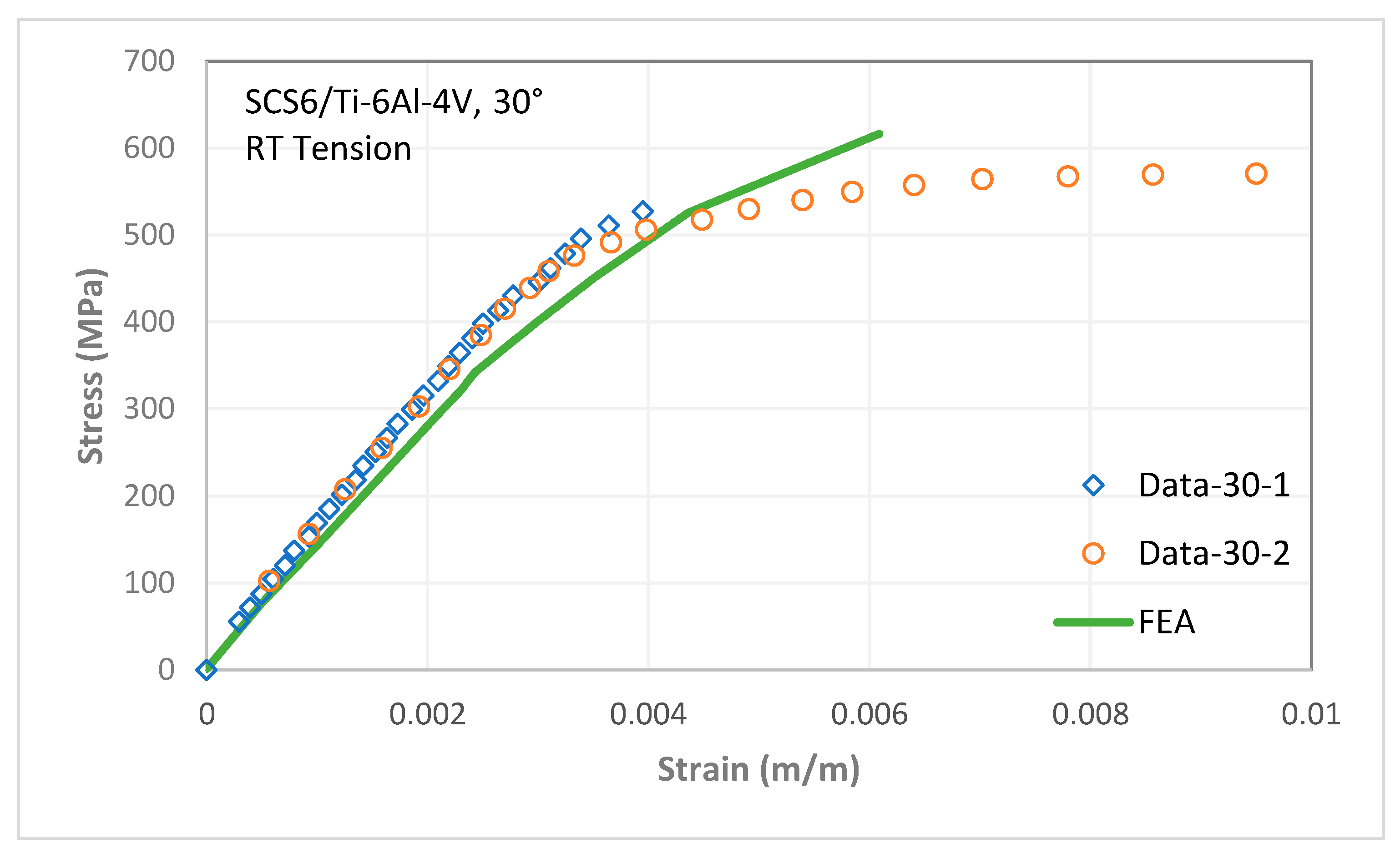
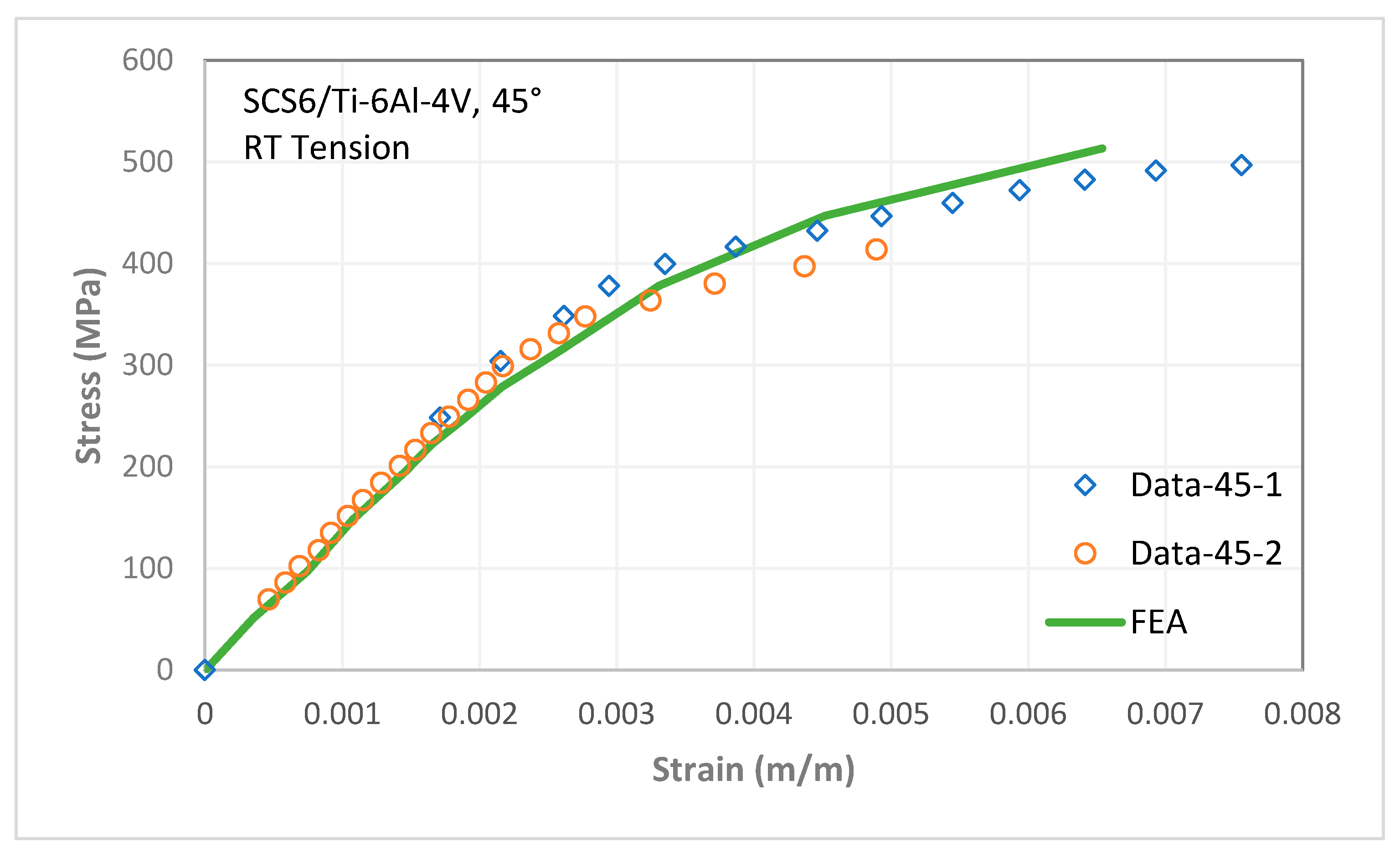
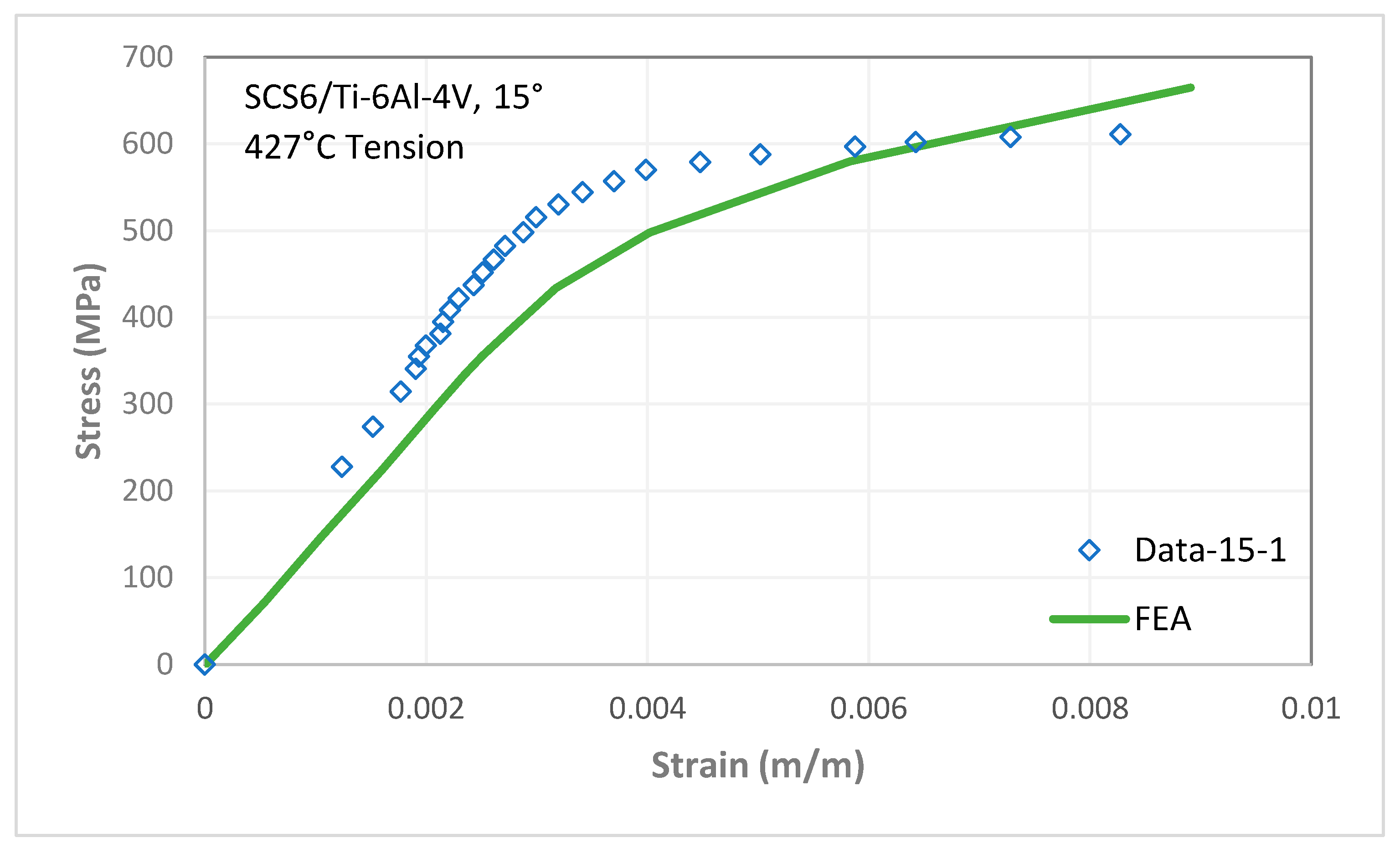
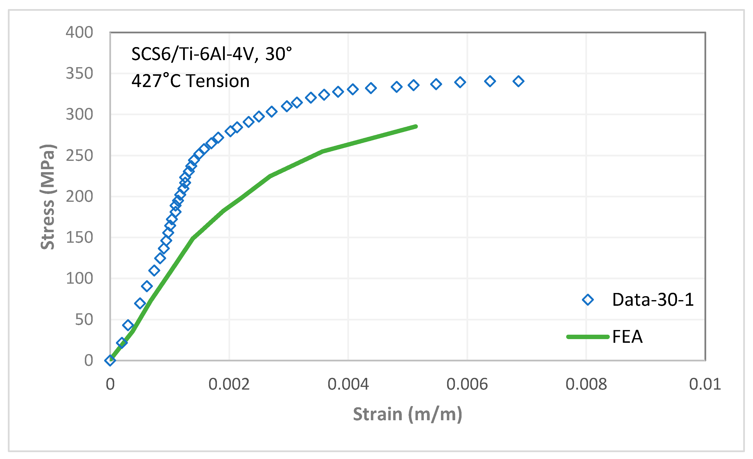
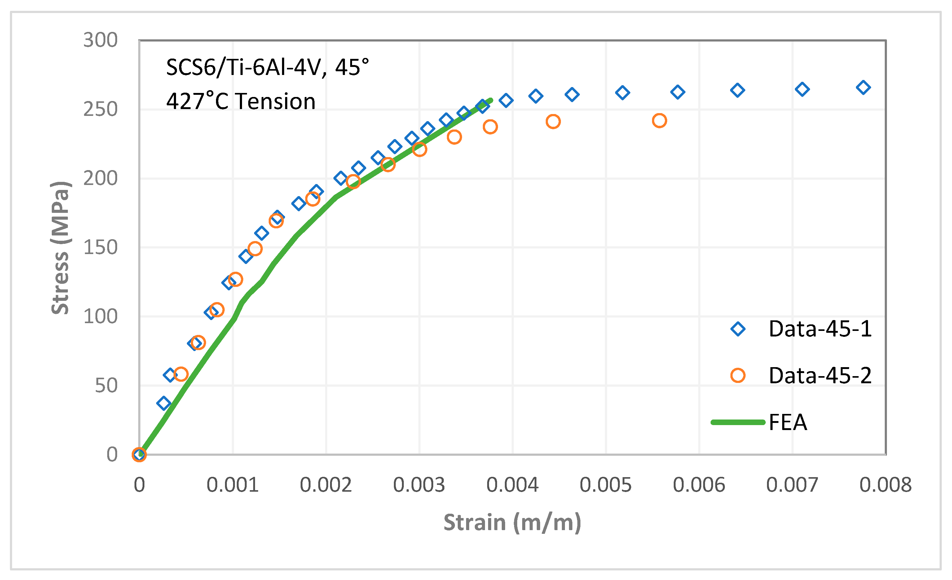
Strains calculated from the unit-cell model were transformed to the specimen coordinate system and plotted against the applied stress. Figure 9, Figure 10 and Figure 11 show the analysis results and test data for the three off-axis angles at RT. Similarly, Figure 12, Figure 13 and Figure 14 show the analysis results and test data for the three off-axis angles at 427 °C. The results show a good comparison for all off-axis angle cases at RT and for the 45° off-axis case at 427 °C. The predicted responses of the 15° and 30° off-axis cases at 427 °C are reasonably close to the measured test data. One of the factors that can improve prediction of damage in 15° and 30° off-axis cases is considering sliding at the fiber-matrix interface. Once there is a better understanding of sliding behavior at the fiber-matrix interface, it can be included in the model to improve the analytical response of off-axis cases where sliding is the dominating factor of micromechanical damage. However, even with all these complexities involved, the above unit-cell model provides solutions that match the experimental data reasonably well.
4. Conclusions
The micromechanical procedure proposed in this paper provides reasonably accurate prediction of MMCs under multiaxial loading. As demonstrated in the comparisons with test data, this procedure can be effectively used to predict the global inelastic response of MMCs under both normal and shear loading by considering matrix inelastic behavior and micromechanical damage (e.g., fiber-matrix separation) in the model. Hence, the proposed approach is a very useful tool for analyzing MMCs under multiaxial stress states.
Author Contributions
Conceptualization, J.A.; methodology, J.A., and U.S.; analysis, S.C., and U.S.; writing, original draft preparation, J.A., U.S. and S.C.; writing, review and editing, J.A. and U.S. All authors have read and agreed to the published version of the manuscript.
Funding
This research received no external funding.
Acknowledgments
The authors would like to express their thanks to Ke Zhang and Golam M. Newaz of Wayne State University, Detroit, MI, for performing material testing.
Conflicts of Interest
The authors declare no conflict of interest.
References
- Chawla, N.; Chawla, K.K. Metal Matrix Composites, 2nd ed.Springer: New York, NY, USA, 2013. [Google Scholar]
- Hayat, M.D.; Singh, H.; He, Z.; Cao, P. Titanium metal matrix composites: An overview. Compos. Part A 2019, 121, 418–438. [Google Scholar] [CrossRef]
- Lee, J.; Elam, S. Development of Metal Matrix Composites for NASA’s Advanced Propulsion Systems, NASA/CP-2001-210427. In Proceedings of the 4th Conference on Aerospace Materials, Processes, and Environmental Technology, Huntsville, AL, USA, 18–20 September 2000. [Google Scholar]
- Toor, Z.S. Applications of Aluminum-Matrix Composites in Satellite: A Review. J. Sp. Technol. 2017, 7, 1–6. [Google Scholar]
- Prasad, S.V.; Asthana, R. Aluminum metal–matrix composites for automotive applications tribological considerations. Tribol. Lett. 2004, 17, 445–453. [Google Scholar] [CrossRef]
- Zweben, C. Advances in composite materials for thermal management in electronic packaging. JOM 1998, 50, 47–51. [Google Scholar] [CrossRef]
- Sun, C.T.; Chen, J.L.; Sha, G.T.; Koop, W.E. Mechanical characterization of SCS-6/Ti-6-4 metal matrix composite. J. Compos. Mater. 1990, 24, 1029–1059. [Google Scholar] [CrossRef]
- Majumdar, B.S.; Newaz, G.M. Inelastic deformation of metal matrix composite: Plasticity and damage mechanisms. Philos. Mag. A 1992, 66, 187–212. [Google Scholar] [CrossRef]
- Majumdar, B.S.; Newaz, G.M.; Ellis, J.R. Evaluation and damage in titanium-based fiber reinforced composites. Metall. Trans A. 1993, 24, 1597–1610. [Google Scholar] [CrossRef]
- Newaz, G.M.; Majumdar, B.S. Deformation and failure mechanism in metal matrix composites. In Proceedings of the Winter Annual Meeting of The America Society of Mechanical Engineers, Atlanta, GA, USA, 17–22 November 1991; pp. 1–6. [Google Scholar]
- Newaz, G.M.; Zhang, K. Inelastic response of off-axis MMC lamina. ASME J. Eng. Mat. Technol. 1998, 120, 163–169. [Google Scholar] [CrossRef]
- Nicholas, T.; Kroupa, J.L. Micromechanics analysis and life prediction of metal matrix composites. ASTM J. Compos. Technol. Res. 1998, 20, 79–88. [Google Scholar]
- Pindera, M.-J.; Bansal, Y. On the micromechanics-based simulation of metal matrix composite response. J. Eng. Mater. Technol. 2007, 129, 468–482. [Google Scholar] [CrossRef]
- Ahmad, J.; Nicholas, T. Modeling of inelastic metal matrix composite under multiaxial loading. In Proceedings of the ASME Symposium on Failure Mechanisms and Mechanism Based Modeling in High Temperature Composites, ASME Winter Annual Meeting, Atlanta, Georgia, 17–22 November 1996; AD-Volume 51/MD-Volume 73, pp. 311–323. [Google Scholar]
- Ahmad, J.; Newaz, G.M.; Nicholas, T. Prediction of metal matrix composite response to multiaxial stresses. Recent Advances in Mechanics of Aerospace Structures and Materials. In Proceedings of the 1998 ASME International Mechanical Engineering Congress and Exposition, Anaheim, CA, USA, 15–20 November 1998; AD-Volume 56. [Google Scholar]
- Santhosh, U.; Ahmad, J. metal matrix composite response under biaxial loading. Constitutive Behavior of High Temperature Composites. In Proceedings of the ASME Winter Annual Meeting, Materials Division, Anaheim, CA, USA, 8 November 1992; MD-Volume 40. [Google Scholar]
- Santhosh, U.; Ahmad, J.; Nagar, A. Non-linear micromechanics analysis prediction of the behavior of titanium-alloy matrix composites. Fracture and Damage. In Proceedings of the ASME Winter Annual Meeting, Aerospace Division, Anaheim, CA, USA, 8 November 1992; AD-Volume 27, pp. 65–76. [Google Scholar]
- Chun, H.-J.; Daniel, I.M. Behavior of a Unidirectional Metal-Matrix Composite Under Thermomechanical Loading. J. Eng. Mater. Technol. 1996, 118, 310–316. [Google Scholar] [CrossRef]
- Dong, M.; Schmauder, S. Modeling of metal matrix composites by a self-consistent embedded cell model. Acta Mater. 1996, 44, 2465–2478. [Google Scholar] [CrossRef]
- Aboudi, J.; Pindera, M.-J. Micromechanics of Metal Matrix Composites Using the Generalized Method of Cells Model: User’s Guide; NASA Contractor Report CR 190756; NASA-Lewis Research Center: Cleveland, OH, USA, 1992. [Google Scholar]
- Shoukry, S.N.; Prucz, J.C.; Shankaranarayana, P.G.; William, G.W. Microstructure Modeling of Particulate Reinforced Metal Matrix Composites. Mech. Adv. Mater. Struct. 2007, 14, 499–510. [Google Scholar] [CrossRef]
- Avila, A.F.; Krishina, T.K. Non-linear Analysis of Laminated Metal Matrix Composites by an Integrated Micro/Macro-Mechanical Model. J. Braz. Soc. Mech. Sci. 1999, 21, 622–640. [Google Scholar] [CrossRef]
- Bednarcyk, B.A.; Arnold, S.M. Micromechanics-based deformation and failure prediction for longitudinally reinforced titanium composites. Compos. Sci. Tech. 2001, 61, 705–729. [Google Scholar] [CrossRef]
- Santhosh, U.; Ahmad, J. An approach for nonlinear modeling of polymer matrix composites. J. Comp. Mater. 2014, 48, 1755–1765. [Google Scholar] [CrossRef]
- Pettermann, H.E.; Huber, C.O.; Luxner, M.H.; Nogales, S.; Böhm, H.J. An Incremental Mori-Tanaka Homogenization Scheme for Finite Strain Thermoelastoplasticity of MMCs. Materials 2010, 3, 434–451. [Google Scholar] [CrossRef]
- Chawla, N.; Chawla, K.K. Microstructure-based modeling of the deformation behavior of particle reinforced metal matrix composites. J. Mater. Sci. 2006, 41, 913–925. [Google Scholar] [CrossRef]
- Qing, H. 2D micromechanical analysis of SiC/Al metal matrix composites under tensile, shear and combined tensile/shear loads. Mater. Des. 2013, 51, 438–447. [Google Scholar] [CrossRef]
- Chandu, S.; Ahmad, J.; Newaz, G.M. Detailed interpretation of off-axis and iosipescu test data on metal matrix composites. J. Reinf. Plast. Comp. 1997, 16, 1156–1167. [Google Scholar] [CrossRef]
- Abaqus 6.11 Analysis User’s Manual: Volumes 1 to 5; Dessault Systems Simulia Corp.: Providence, RI, USA, 2011.
- Kroupa, J.L.; Bartsch, M. Influence of viscoplasticity on the residual stress and strength of a titanium matrix composite after thermomechanical fatigue. Compos. Part B-Eng. 1998, 29, 633–642. [Google Scholar] [CrossRef]
- ASTM D3379-75(1989)e1. Standard Test Method for Tensile Strength and Young’s Modulus for High-Modulus Single-Filament Materials; ASTM International: West Conshohocken, PA, USA, 1975; Available online: www.astm.org (accessed on 2 February 2016).
- Kirkpatrick, S.W. Damage and Failure Behavior of Metal Matrix Composites under Biaxial Loads. Ph.D. Thesis, Stanford University, Stanford, CA, USA, September 1998. [Google Scholar]
Figure 1.
Typical off-axis test specimen configurations showing (a) specimen dimension and (b) boundary conditions and extensometer location.
Figure 1.
Typical off-axis test specimen configurations showing (a) specimen dimension and (b) boundary conditions and extensometer location.

Figure 2.
Three-dimensional finite element model of the unit-cell.

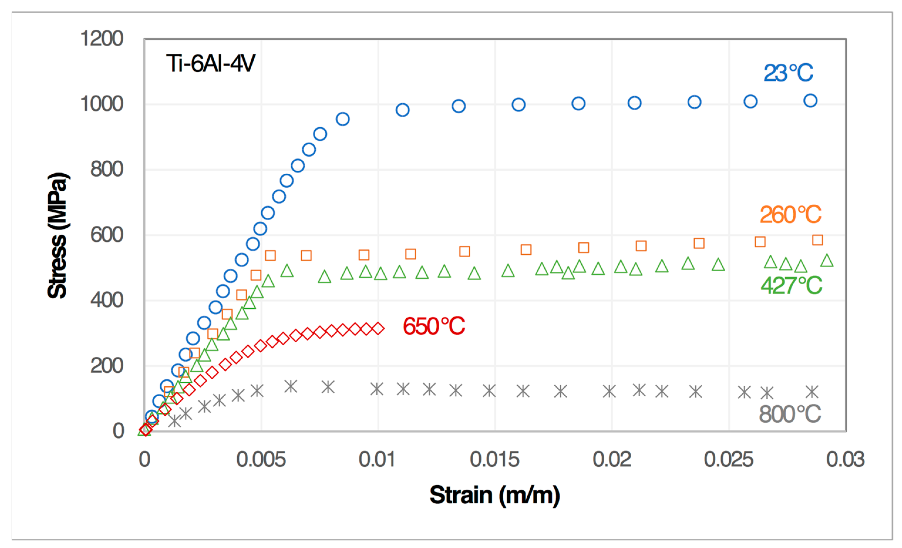
Figure 3.
Uniaxial stress-strain curves for Ti-6Al-4V matrix material.

Figure 4.
Tensile test data of unidirectional SCS-6/Ti-6Al-4V composite for 0° and 90° loadings at 23 °C.
Figure 4.
Tensile test data of unidirectional SCS-6/Ti-6Al-4V composite for 0° and 90° loadings at 23 °C.

Figure 5.
Tensile test data of unidirectional SCS-6/Ti-6Al-4V composite for 0° and 90° loadings at 427 °C.
Figure 5.
Tensile test data of unidirectional SCS-6/Ti-6Al-4V composite for 0° and 90° loadings at 427 °C.

Figure 6.
Stress contours ( component in MPa) in unit-cell at reference temperature of 23 °C.

Figure 7.
Micromechanics analysis approach for off-axis tests.

Figure 8.
Finite element mesh of a composite specimen used in global analysis.

Figure 9.
Stress-strain response for 15° off-axis at 23 °C.

Figure 10.
Stress-strain response for 30° off-axis at 23 °C.

Figure 11.
Stress-strain response for 45° off-axis at 23 °C.

Figure 12.
Stress-strain response for 15° off-axis at 427 °C.

Figure 13.
Stress-strain response for 30° off-axis at 427 °C.

Figure 14.
Stress-strain response for 45° off-axis at 427 °C.


Table 1.
Stress states in off-axis tests.
| θ (°) | σ11 | σ22 | σ12 |
|---|---|---|---|
| 0 | 1 | 0 | 0 |
| 15 | 0.933 | 0.067 | 0.25 |
| 22.5 | 0.854 | 0.146 | 0.354 |
| 30 | 0.75 | 0.25 | 0.433 |
| 45 | 0.5 | 0.5 | 0.5 |
| 60 | 0.25 | 0.75 | 0.433 |
| 90 | 0 | 1 | 0 |
Table 2.
Properties of SCS-6 fiber and Ti-6Al-4V matrix materials.
| Properties | SCS-6 [23] | Ti-6Al-4V | ||
|---|---|---|---|---|
| 23 °C | 427 °C | 23 °C | 427 °C | |
| Young’s Modulus (GPa) | 393 | 378 | 120 | 95 |
| CTE (μm/m°C) | 3.2025 | 3.9197 | 8.78 | 10.71 |
| Poisson’s Ratio | 0.25 | 0.25 | 0.31 | 0.31 |
| Yield Strength (MPa) | - | - | 880 | 460 |
Table 3.
Linear micromechanics analysis results.
| SCS-6/Ti-6Al-4V | 23 °C | 427 °C |
|---|---|---|
| E11 (GPa) | 194 | 171 |
| E22 (GPa) | 162 | 134 |
| E33 (GPa) | 162 | 134 |
| v12 | 0.311 | 0.316 |
| v13 | 0.292 | 0.291 |
| v23 | 0.292 | 0.291 |
| G12 (GPa) | 62 | 51 |
| G13 (GPa) | 58 | 47 |
| G23 (GPa) | 58 | 47 |
| α1 (μm/m°C) | 5.81 | 6.75 |
| α2 (μm/m°C) | 7.51 | 9.21 |
| α3 (μm/m°C) | 7.51 | 9.21 |
Table 4.
Global stress analysis results for unit-applied stress.
| θ (°) | σ11 | σ22 | σ12 | σ33 = σ23 = σ31 |
|---|---|---|---|---|
| 15 | 0.933 | 0.067 | 0.25 | 0 |
| 30 | 0.75 | 0.25 | 0.433 | 0 |
| 45 | 0.5 | 0.5 | 0.5 | 0 |
© 2020 by the authors. Licensee MDPI, Basel, Switzerland. This article is an open access article distributed under the terms and conditions of the Creative Commons Attribution (CC BY) license (http://creativecommons.org/licenses/by/4.0/).
Share and Cite
MDPI and ACS Style
Ahmad, J.; Santhosh, U.; Chandu, S. A Nonlinear Analysis Interpretation of Off-Axis Test Results in Metal Matrix Composites. J. Compos. Sci. 2020, 4, 127. https://0-doi-org.brum.beds.ac.uk/10.3390/jcs4030127
AMA Style
Ahmad J, Santhosh U, Chandu S. A Nonlinear Analysis Interpretation of Off-Axis Test Results in Metal Matrix Composites. Journal of Composites Science. 2020; 4(3):127. https://0-doi-org.brum.beds.ac.uk/10.3390/jcs4030127
Chicago/Turabian StyleAhmad, Jalees, Unni Santhosh, and Swamy Chandu. 2020. "A Nonlinear Analysis Interpretation of Off-Axis Test Results in Metal Matrix Composites" Journal of Composites Science 4, no. 3: 127. https://0-doi-org.brum.beds.ac.uk/10.3390/jcs4030127