Mechanisms of Origin and Classification of Out-of-Plane Fiber Waviness in Composite Materials—A Review


1
Research Group of Lightweight Design and Composite Materials, University of Applied Sciences Upper Austria, Stelzhamerstraße 23, 4600 Wels, Austria
2
Institute of Materials Resource Management, University of Augsburg, Universitaetsstraße 1 Nord, 86159 Augsburg, Germany
*
Author to whom correspondence should be addressed.
J. Compos. Sci. 2020, 4(3), 130; https://0-doi-org.brum.beds.ac.uk/10.3390/jcs4030130
Submission received: 11 August 2020
/
Revised: 24 August 2020
/
Accepted: 3 September 2020
/
Published: 4 September 2020
Abstract
:Out-of-plane fiber waviness, also referred to as wrinkling, is considered one of the most significant effects that occur in composite materials. It significantly affects mechanical properties, such as stiffness, strength and fatigue and; therefore, dramatically reduces the load-carrying capacity of the material. Fiber waviness is inherent to various manufacturing processes of fiber-reinforced composite parts. They cannot be completely avoided and thus have to be tolerated and considered as an integral part of the structure. Because of this influenceable but in many cases unavoidable nature of fiber waviness, it might be more appropriate to consider fiber waviness as effects or features rather than defects. Hence, it is important to understand the impact of different process parameters on the formation of fiber waviness in order to reduce or, in the best case, completely avoid them as early as possible in the product and process development phases. Mostly depending on the chosen geometry of the part and the specific manufacturing process used, different types of fiber waviness result. In this study, various types of waviness are investigated and a classification scheme is developed for categorization purposes. Numerous mechanisms of wrinkling were analyzed, leading to several recommendations to prevent wrinkle formation, not only during composite processing, but also at an earlier design stage, where generally several influence factors are defined.
1. Introduction
Fiber-reinforced composite materials allow for a significant mass reduction due to the comparably low density (c.f. four to five times less than steel) and, in addition, fibers can be aligned in accordance with the load paths. This possibility of alignment allows the fibers to be placed at the exact position where they are needed to provide the component with the required stiffness and strength. However, this can lead to a load path-optimized composite structure, which is not necessarily easy to produce and free of defects. The placement of the fibers or semi-finished textile products is still often carried out by hand-lay-up, especially in the aviation industry. This allows a diverse draping of the unidirectional (UD) layers, woven textiles, or non-crimped fabrics (NCF) onto the production tool. However, manufacturing effects such as fiber waviness, porosity, delamination, and distortion cannot be completely avoided. The increased demand for composite components and their production process stability for the aviation and automotive industries requires a transition to at least partially automated manufacturing processes. Those systems come with a higher deposition rate and ensure reproducible quality, but also imply production effects (e.g., fiber waviness) [1,2]. This necessitates a sophisticated understanding of those implicit effects on the mechanical properties of the manufactured structure.
The decision as to whether these unwanted irregularities are considered as manufacturing features (effects), or as defects, depends on the size, number, and location in the component. Those allowance limits depend on the strength and stiffness reserve at the location of the feature, as well as on functional requirements (e.g., water tightness). The assessment of manufacturing effects further depends on the industry. In the aviation industry, the allowance limits for defects are very restricted, while in the automotive industry the need for short cycle times leads to a trade-off between robust processes and tolerated manufacturing imperfections. To this point, there is still no generally accepted approach to quantitatively support accept/reject/repair decisions and make a consistent assessment of wavy layers in composites. If the effect is termed to be a defect, typically a deviation from design must be requested in the aviation industry and an individual decision must be made on “use as is”, repair, or reject entirely. In some cases, experiments on representative test samples are performed at the subcomponent-level on a statistical basis. However, this is both time consuming and cost intensive. It is necessary to strive for a fiber-oriented and in particular a manufacturing-oriented design and construction of composite components. Towards this goal, design and production engineers aim to expand the permissible margin of safety by assessing the effect on stiffness and strength of those production effects (i.e., fiber waviness, porosity, delamination, etc.). Additionally, they aim to reduce or, in the best case, avoid them on the process side, increasingly with the help of finite element based process simulations, such as in [3,4,5].
2. Definition of Terms
There is no universally accepted terminology and consistent use for the differentiation between waves, wrinkles, folds, undulations, and misalignments (Figure 1). Definitions of these terms are given below for the sake of clarity. Ply/Fiber waviness or wrinkling is a commonly observed manufacturing effect in composite parts resulting in decreased mechanical performances. Fiber waviness is denoted as a wave-formed ply and/or fiber deviation from a straight alignment in a unidirectional laminate. This may arise as an undesirable manufacturing effect that commonly occurs during draping, infiltration, and/or consolidation/curing process steps. Sometimes these waves are also referred to as marcels. If the out-of-plane fiber waviness occurs due to stability issues when the ply is loaded under compression, it is also referred to as buckles or fiber buckling.
Wavy plies can appear in arbitrary shapes and locations and can principally be classified into in-plane and out-of-plane waves, whereas Nelson et al. [6] stated, that both show similar strength degradations. This paper aims to investigate out-of-plane waviness because of its more frequent occurrence compared to in-plane waviness. In this work, folds are considered as a special type of waviness with a maximum deviation of the fiber misalignment where a layer comes into contact with itself. Undulations are considered to be small-sized fiber misalignments at the mesoscopic level in the form of waves inherent to various preform manufacturing processes, such as woven textiles where fibers are undulated between warp and weft directions. Due to the undulations, woven fabrics show a systematically lower stiffness and different damage behavior compared to UD layers. This influence has been intensely investigated by [7,8,9,10]. Fiber misalignment is the general description for the angular deviation of nominal, intended fiber directions and; therefore, not corresponding to the designed fiber path. Misaligned fibers remain straight compared to curved fibers in waves, wrinkles, or undulations. Nevertheless, in many publications the term fiber misalignment is used as an umbrella term including waves, wrinkles, and undulations.
3. Parameters
In general, the shape of fiber waviness is described by the ratio of amplitude to wavelength. Davidson and Waas [11] introduced six parameters to characterize the wave, indirectly including the laminate thickness. While amplitude A and wavelength L are most commonly used to describe the wave (Figure 2), the maximum deviation θmax is considered to have the greatest impact on the mechanical properties. Important influencing parameters such as maximum deviation of the fiber orientation from the original orientation, as well as the laminate thickness [12], have received little attention in previous investigations. The wave pattern is typically represented mathematically as sinusoidal waves [13,14]. El-Hajjar and Petersen [15] used a Gaussian function to capture the bell curve of wavy plies, which was found to better represent the wave geometry. Nevertheless, there are a few more parameters that can influence the mechanical behavior and thus have to be considered. Results in [16] show that the position of wavy layers in the cross-section of a laminate also has a significant influence on the strength reduction. A more outward position of wavy layer leads to a greater decrease in strength, since the layers on the edge of the laminate are supported only one-sided and; therefore, fail earlier.
4. Occurrence of Fiber Waviness
The origins of fiber waviness are manifold and can be caused by several factors. These effects can occur in manual hand lay-up processes, which are strongly influenced by the skills of the operators, but also in highly automated production processes. Any composite manufacturing process is associated with a number of specific effects. The classification of waviness-inducing effects serves as an overview of the numerous origins and influence factors on the formation of out-of-plane fiber waviness and provides a general guideline on how to reduce and, in the best case, even avoid the occurrence of wavy layers at an early stage of product and process development.
4.1. Mechanical Loading and Behavior of Dry and Impregnated Fiber Reinforcements
4.1.1. Basic Material Behavior
The deformation behavior of fiber-reinforced plastics is very different from that of isotropic materials. With isotropic materials, normal stresses only cause normal strains and shear stresses only shear strains. Within consolidated/cured fiber-reinforced plastics, this decoupling is only possible under certain conditions, if symmetries are introduced in the stacking sequence. In the most general case all elements of the (ABD) matrix [17], that relates cross-sectional forces and moments to mid-plane strains and curvatures which are occupied and thereby extensional, shear, bending, and twisting behavior are coupled. However, during the process, the matrix is either absent (e.g., in initially dry reinforcements in LCM processes), melted (e.g., in thermoforming processes using thermoplastic matrices), or in an uncured sticky stage when using thermoset pre-impregnated reinforcements. In dry or pre-impregnated composites, independent if a thermoplastic or thermoset matrix is used, the extensional and bending behavior is decoupled, which makes the use of the [ABD] matrix in fact not appropriate. Classical plate and shell theories do not apply in their standard form for dry or non-cured composites, since, opposite to continuous materials, there is no direct relation between the extensional and bending stiffness. According to Boisse et al. [4], the quasi-inextensibility and the possible slippage between fibers are the two main reasons for the very specific mechanical behavior of fiber reinforcements. The relative slippage between fibers, which is described in detail in Section 4.4.1, leads to a much lower bending stiffness than for continuous materials such as cured composites, metals, or polymers.
When considering a single ply, the thickness of a typical ply is much smaller than the width, and therefore the bending stiffness out-of-plane is much smaller than in-plane, consequently out-of-plane is the predominantly occurring case of waviness. In [18] it is stated, that thermoset pregregs are more prone to fiber buckling in form of wavy layers because of their lower bending stiffness compared to layers used for liquid composite molding processes which are usually thicker. As shown in Figure 3, plies with higher bending stiffness tend to single wave formation, whereas low bending stiffness plies tend to form a higher number of waves.
An instability phenomenon, known as shear-buckling, can occur in forming composite materials leading to pronounced out-of-plane wrinkling. An example of this mechanism can be also observed, for example, in simple off-axis tensile tests of unidirectional prepregs (Figure 4). However, this phenomenon is not limited to single unidirectional laminates and may also occur in cross-ply or quasi-isotropic laminates mainly dependent on the forming rate and the preform dimensions (i.e., the ratio of the initial preform size to the formed surface area) [20,21].
4.1.2. Mechanical Deformation of Layers Due to Manual Handling of Preforms, Moving Sliders, and Closing Tools
Fiber misalignment in general, and fiber waviness specifically, often originate from the labor-intensive preform placement into the mold cavity prior to infiltration and curing steps. The quality of draping is therefore strongly dependent on the skill and experience of the operator. Fiber waviness may be also formed due to mold closure effects when the fiber preform is compressed during mold closing, inducing tension forces around curvatures and bends, particularly in massive, geometrically-complex parts or when sliders move the plies away from its intentional position. In [22,23,24,25], it was stated that fiber waviness can also occur when slightly oversized preforms are forced to fit into a mold cavity. This is not considered to be a manufacturing effect but more a design issue, as this problem can be solved by adapting the size of the ply.
4.2. Path Length Differences
4.2.1. Micro/Meso Scale Deformation at the Material Level
Bended continuous fiber-reinforcements tends to form out-of-plane waviness as a result of path length differences between the upper and lower side of the ply [1]. This effect is considered to be caused at the material level (micro/meso scale). When forming a multiple-ply stack, each ply is exposed to these path length differences. In addition to that, waviness can occur if the ability of the plies to slip between each other is too low or even constrained. This effect can be controlled by the forming rate, temperature control and the distance of the point of forming to the free edge where the necessary slip between the plies must be accommodated [1].
4.2.2. Global Deformation on Structural Level at Double Curved and Joggled Geometries
When a material, regardless of whether it is dry or pre-impregnated, is draped around a double curved surface (e.g., hemispheres [1,26] or joggled geometries [5,27,28,29,30,31]), the path length difference of the reinforcement and the path on the geometry to which the material must map on the surface can vary significantly, thus leading to a pronounced risk of wrinkling of the layers due to path length differences at the structural level (macro scale). The drapeability of a material describes its ability to conform to the mold surface without fiber distortion, movement, and out-of-plane buckling. The complexity of the final part tremendously influences the occurrence of fiber waviness. Potter et al. [1] stated that only a slight difference in path length can lead to obvious fiber waviness. A schematic illustration of path length differences between the edges of tows on the surface of a hemisphere is shown in Figure 5.
Furthermore, the probability of fiber waviness is strongly dependent on the pathway, as there are generally several ways by which the draping can be achieved [32]. Especially the placement of fiber reinforcements by hand allows for a very diverse draping into the production tool, but the occurrence of fiber waviness cannot be completely avoided. Depending on the pathway, higher or lesser skills of the operators are required to achieve a defect free part. The effect of differences in the path length strongly depends on the choice of material and the geometry design. During the deformation of the material, the curvature and the stresses generated in the material change. These are, according to Lin et al. [33], functions of time, temperature, processing rate and holding force. Wrinkling may occur by buckling of the tows along the circumference of the hemisphere if the compressive force exceeds the critical buckling force. Several experimental studies [34,35,36,37,38,39] have reported that, amongst other factors, stress conditions induced by manufacturing boundary conditions, deforming rates, original blank dimensions and strain gradients play a role in their development. Boisse et al. [26] have also shown that the formation of out-of-plane wrinkles is a global phenomenon dependent on process conditions (e.g., blank-holder pressure, and all types of strains and rigidities of the composite material). Low forming speeds also reduce the possibility of wrinkling by generating lower resistance to inter-ply and intra-ply shearing, thus allowing the blank to deform more easily [40,41]. Generally, when the draped reinforcement arrives at a flat region, the distortions in the tows needed to accommodate the curvature continue across the flat regions [1]. The tendency of wrinkling, occurring from a so-called drape run-out, is significantly reduced if the layers to be formed have a shape and size which results in as little excess material as possible at the edges [42]. These wrinkles can be, at least partially, avoided by blank holder forces to keep the plies under slight tension during molding in forming processes. As shown in numerous studies [26,33,40,43,44], keeping the blank under suitable in-plane tension by the presence of blank holder forces can, significantly minimize the occurrence of fiber waviness and increase the quality of the formed parts. The clamping force depends on both reinforcement architecture (e.g., unidirectional or fabric) and forming ratio (i.e., ratio of blank area and the projected area of the die cavity) [44]. The type of holding fixture and the position of springs is usually determined by prior experience and considerable trial and error or, increasingly, with the help of process simulations. The blank holder may induce tensile stresses by spring elements or vertical clamping rings used to keep the flange flat.
In diaphragm forming, the outer edges of the blank are pressed onto the mold flanges before the central area is drawn into the cavity when using female tools. In addition, the friction between the blank surfaces and the diaphragm create biaxial tensile stresses in the blank as the diaphragm is stretched, which prevent wrinkle formation due to out-of-plane buckling [44]. Additional forces that can reduce the formation of wrinkles in diaphragm forming processes originate from the inherent resistance of the material itself and from the restraining force supplied by the diaphragm when it is stretched [45]. The combination of both prevents out-of-plane wrinkling in diaphragm formed components even in the absence of clamping or blank holder forces [44]. In addition to the suppression of wrinkle formation during press forming, according to [46], blank holders serve several more functions (e.g., they prevent the shrinkage of the blank during preheating, they maintain the fiber orientation in the softened blank when it is transferred from the oven to the mold, and they allow for a rapid transfer of the preheated blank to the mold without significant heat loss). Lin et al. [33] used experimental and numerical (FE) approaches to determine the effects of clamping and blank holding forces on the wrinkling behavior. In an example of 3D stamp forming [44], schematically illustrated in Figure 6, a reduction in area of the individual sections occurs when travelling into the cavity of the mold [47,48], inducing hoop forces, which resolve into compressive stresses perpendicular to the radius of the circular laminate. Fiber wrinkling and distortions are observed around the periphery of the cavity and in the flange area if stamping forces generated during forming exceed the critical buckling stress.
Clamping forces create desirable frictional forces, FR, which act in opposite direction to the material flow as the material is drawn into the cavity. Since the material cannot stretch in fiber direction due to virtually inextensible fibers, the fibers have to move from the outer edges of the sheet towards the center causing tensile stresses in fiber direction. According to Friedrich et al. [44], the decrease in area when moving towards the apex of the dome section simultaneously leads to compressive hoop stresses in the bisecting direction of the reinforcements which are resolved in out-of-plane buckles appearing in the direction away from the fibers. Dependent on the mold geometry inter-ply slip, inter-ply rotation and transverse matrix flow are necessary in order to form a component without instabilities such as out-of-plane buckling.
The forming behavior of pre-stacked prepregs subsequently formed in a hot drape forming (HDF) process using a spar geometry with a flange recess area (varying cross section), shown in Figure 7, was investigated by [5,28,29,30,31]. Hallander et al. [28] experimentally studied the out-of-plane defect behavior during forming in the recess area investigating various parameters (e.g., lay-up sequence, prepreg ply thickness, inter-ply friction, and prepreg ply impregnation). The lay-up sequence was shown to have a dominant effect. [0/90] and [45/−45] layups in a UD prepreg are less sensitive for out-of-plane defects compared to a quasi-isotropic lay-up. The lay-up that is more prone to shear, also deforms better during forming without visible defects. The study further shows the existence of compression in the laminate in the recess area that is globally under tension during forming. Åkermo et al. [29] and building on this, Sjölander et al. [5], studied the inter-ply friction by performing numerical simulations on the same geometry using the software AniForm. They modelled the rubber like diaphragm by the hyperelastic Mooney-Rivlin material model. The fibers are modelled as linearly elastic and the matrix by a combination of a viscous and an iso-elastic material model, a so-called Kelvin-Voigt model. The inter-ply friction was modelled by two different friction models, a penalty model that combines viscous and Coulomb friction and a penalty polymer friction model. The simulations confirmed the presence of compressive stresses across the recess area of the considered spar. The bending stiffness was modelled with an orthotropic elastic model to simulate the difference in bending stiffness in the fiber direction and the transverse fiber direction. In [30], Hallander and colleagues investigated the influence of locally changed ply properties or cuts on the wrinkling behavior during forming. Local cuts of layers were used to reduce the stresses that develop in the recess area. In [31], Hallander et al. experimentally studied the forming behavior by locally manipulating the prepreg interfacial characteristics (i.e., primarily increasing prepreg surface friction), in order to cause different pairs of plies to interact during forming. This manipulation is performed by using either multi wall carbon nano tubes (MWCNTs) or a thermoplastic veil at the desired interlayers.
Additionally, wrinkles originating from the forming of pre-stacked prepregs, can be, at least partially, reduced by higher consolidation pressure during a subsequent autoclave curing.
For parts with significant double curvature and requiring the use of a large area draped reinforcement layer, the selection of a woven fabric with a narrow rather than a wide tow reduces the level of fiber waviness [22]. By including these influencing factors in the design decisions, this effect can be reduced.
4.2.3. Steering
In automated fiber placement (AFP) [49], a fully automated manufacturing process for ribs or flat composite components, robot-guided fiber-reinforced prepreg tows are placed along a predetermined path on the three-dimensional tool surface using pressure and temperature. Due to the path steering of the head, the layers can be ideally orientated according to a pre-defined load path. However, different defects may occur (e.g., bridging, gaps between the deposited tow, in-plane or out-of-plane buckling of the tow, or a lifting of the tow on the outside of the tow as the radius narrows). Overall, the formation of these defects is a function of the steering radius chosen in the design process.
A schematic overview of tow steering defects is given in Figure 8. During steering, the tow is bent in the plane of the surface, which causes the fibers along the inner edge to be under compression and the outer edge to be under tension [50]. The inner edge of a tow placed along a curved trajectory tends to buckle in the form of localized out-of-plane waviness when the radius reaches a specific limit. This limit depends on parameters such as tow width and thickness, material, temperature control, etc. The tape/tow pull-off/pull-up [50,51] is caused by the tension state at the outer edge of the steered tow. The mechanical behavior of the fiber mainly determines the resulting cylindrical deformation mode. The fiber can be assumed to be almost inextensible, causing high tensile stresses. In combination with an insufficient prepreg tack, the tow starts to fold at the outer edge. In-plane fiber waviness and out-of-plane tow buckling are two effects that are assumed to occur subsequently [51].
Hörmann [51] states that, in a first step, the compression at the inner edge of the tow due to the in-plane curvature causes in-plane fiber waviness by shearing the non-cured, thermoset matrix between the fibers. Subsequently, the tows start to form out-of-plane buckles, if the in-plane curvature reaches a particular, material-dependent limit and the prepreg tack is insufficient to hold the tow on the substrate surface. A comprehensive review on manufacturing-induced imperfections in composite parts manufactured via AFP is given by Heinecke and Willberg [53].
A careful control and selection of process parameters [54,55,56,57,58] (i.e., heating temperature, compaction pressure, deposition rate), machine trajectories (i.e., steering radius), together with material parameter (i.e., tackiness and tow width), is of crucial importance for obtaining a high-quality, defect-free laminate. Bakhshi et al. [55] carried out experimental and analytical studies to understand the time-dependent wrinkle formation during tow steering in AFP. The analytical model to describe wrinkle formation accounts for process parameters (e.g., temperature, radius, compaction force, speed) together with interface properties (tack). An analytical model (Ritz) was developed by Beakou et al. [54] to estimate the critical buckling load of a tow and, consequently, the minimum steering radius for a circular fiber path. The analytical approach accounts for prepreg tack and stress distribution; however, two important parameters (i.e., lay-down rate and delay in tow wrinkling recovery) were additionally found to be important to describe tow wrinkling. Sensitivity studies by Beakou et al. [54] have shown that the prepreg tack and the tow width strongly affect the critical buckling load. However, care must be taken to avoid stretching of the outer fiber of the tow to prevent lateral compressive stresses leading to a transverse buckling phenomenon. Lower compaction forces lead to placement without tow wrinkling; however, a minimum force must exist to ensure tack. For productivity reasons, manufacturers strive for high deposition rates. Figure 9 shows an anisotropic plate on elastic foundation illustrating an approach by Béakou et al. [54] and Hörmann [51] to describe out-of-plane tape buckling for a steered tape during automated fiber placement. An anisotropic plate which is geometrically defined by its length l, width h, and thickness d, rests on an elastic foundation defined by its elastic stiffness k. The plate is subjected to combined in-plane bending and tension, causing the position of the neutral axis to deviate from the position of the symmetric axis. The inner edge is assumed to be under compression and out-of-plane buckling is allowed. However, it was observed by Beakou et al. [54] that high deposition rates promote the occurrence of tow wrinkling. As a rule, the minimum steering radius without tow wrinkling increases from 1.5 to 4 m when the lay-down rate increases from 12 to 30 m/min. Depending on processing parameters, tow wrinkling may also return many hours after fiber deposition. Matveev et al. [59] developed an analytical framework for the prediction of wrinkling in tow steering during automated dry fiber placement (ADFP). Experimental results were used for estimation of the model parameters and to validate the analytical model. The tackiness was shown to have the greatest influence on critical steering radius. The lay-up temperature influence tack stiffness and hence can improve wrinkle formation, respectively decrease the steering radius. Kim et al. [60] found that the key factor causing all process-induced defects in automated fiber placement (AFP) and tailored fiber placement (TFP) is the in-plane bending deformation of the tow. Table 1, taken from Blom [50], shows process limits for minimum steering radii as a function of the tape width. The given values are purely kinematic and do not consider the process-material interaction. However, according to Blom, much smaller steering radii are possible depending on the used material system, the lay-up speed, and compaction force.
Rajan et al. [61] performed experimental studies using Stereo-DIC to obtain in-situ measurements for quantifying out-of-plane wrinkle formation and in-plane deformations occurring during automated fiber placement (AFP). Viisainen et al. [62] used in-situ Stereo-DIC during forming experiments on a double curved hemisphere. Rajan et al. [61] found that tow wrinkling can be observed in all tows at each location where the underlying laminate substrate showed surface defects such as gaps and overlaps. It has been observed that the wrinkle amplitude increases during the first hour of lay-up to almost twice the amplitude of the wrinkle immediately after placement, apparently due to viscoelastic effects in the prepreg tack. Another mechanism observed is that, after applying heating to the steered tape, close adjacent wrinkles tend to merge into one large wrinkle, apparently due to considerable loss in stiffness of the cohesive layer between the tape and substrate.
4.2.4. Consolidation in Corner Areas, External Radii, Stepped, or Tapered Laminates
The autoclave consolidation of thick laminates in inner corner geometries can force the plies to move in the corner direction and form wrinkles due to the pressure acting at the end of the layup (Figure 10). This effect depends on the length of the laminate arm (limb length) as it influences the possibility of ply slippage and; therefore, can be addressed in design decisions and manufacturing planning. Further mechanisms of fiber waviness in internal radii are described in Section 4.3.4, of which may occur due to ply or vacuum bag bridging.
In V-bending [44], the compressed fibers in the bend region can lead to wrinkling provided the compressive stresses exceed a certain limit. In contrast, Potter et al. [1] state that even a small amount of consolidation of the plies over an external corner can lead to an excess length that must be accommodated by the forming of wrinkles if no slippage can occur.
The debulking of the plies over an external radius during the consolidation process ensures a correct fit on the tool geometry and improves adhesion between the layers. The outermost plies are forced into a tighter geometry, leading to an excess length. Figure 11a,b shows these two possible scenarios when a laminate is consolidated over a corner radius and the excess length is accommodated by slippage of the plies or the occurrence of waviness.
If layers can shear/slip over one another, the additional length can be accommodated by producing so-called “bookends” [18], which are shown in Figure 11c. However, if the tack between the plies is too high, axial compressive stresses are built up in the layers which may form wrinkles.
Dodwell et al. [18] developed an analytical model for the description of out-of-plane wrinkling due to consolidation over non-trivial geometries. The model determines the critical strain energy at which the layers begin to buckle. Several assumptions and simplifications have been made for this analytical approach. In reality wrinkling is dependent on a complex mix of non-linear geometry and viscoelastic temperature-dependent rheological behavior. A critical limb length is derived from the model, which depends mainly on layer thickness and shear properties and less on the tool radius.
where is the critical load and the shear stress.
During many advanced composite processes (e.g., autoclave process or compression molding), bulk compressive stresses [63] are applied to the reinforcement in thickness direction leading to an increased fiber volume fraction. During consolidation, the fiber reinforcement begins to take up an increasing amount of the applied compression load. Bulk compressive stresses that are applied in the absence of any axial stress represent similar conditions occurring during autoclave processes. For this case, an expression [63] can be obtained that relates the bulk compressive stress with the fiber volume fraction,
with initial fiber volume fraction, maximum allowable fiber volume fraction, and current fiber volume fraction, respectively. If the axial extension induced by transverse compression is constrained, the applied compression bulk stress would lead to an induced axial compression increasing the potential for fiber wrinkling [63].
The size of radius plays an important role, especially in internal corners. It becomes more difficult to place the prepregs accurately into internal corners with decreasing radius. The quality of the layup strongly depends on the size of radius, the ply thickness and the final laminate thickness. Larger corner radii are less likely to be bridged and, according to [22], will definitely have lower levels of fiber waviness induced by the curvature of the prepreg. Although heavier grades of prepregs potentially reduce the labor cost due to a reduced number of plies, the level of fiber waviness induced by the curvature would increase. When processing out-of-autoclave prepregs using vacuum bag only, the challenge is to extract the remaining air from the part prior to curing. For this purpose, these prepregs, also called semipregs, have a dry area ensuring a connected flow path, but resulting in a very high bulk factor.
The bulk factor [64], which describes the ratio of the initial laminate thickness to the final thickness of the fully impregnated part after curing, is an inherent characteristic of the material. Materials with high bulk factors (e.g., out-of-autoclave semipregs) are more prone to wrinkling compared to low bulk factor plies (e.g., traditional prepregs). To improve the laminate quality and reduce the risk of fiber waviness, pre-consolidation every four to five layers using a vacuum bag is recommended. This is especially important for reinforcements with high bulk factors. However, Lightfoot et al. [65] reported that frequently conducted debulks during hand lay-up had no influence on the wrinkle formation compared to non-intermediate debulks.
The relationship shown in Equation (3) is not valid in corner regions, because of the curvature, the material undergoes a more complex compaction (i.e., corner thinning and thickening). Typical values for the bulk factor [64] range between 1.08–1.17 for unidirectional plies and 1.15–1.4 for woven fabrics, meaning a ~8–17%, respectively, ~15–40% lower final thickness compared to initial laminate thickness. Levy and Hubert [66] developed an analytical model for the prediction of thickness deviation in both male and female corner regions by distinguishing between two phenomena. The friction dominated mechanism describes the interply friction which can hinder the layers from adapting to the mold geometry, thus preventing a proper compaction in the corner [18]. In a previous work by Hubert and Poursartip [67], they stated that even if interply slippage occurs, the bagged surface may differ from the facing mold surface due to the curvature in the corner. The available consolidation pressure in the part then differs from the expected vacuum bag pressure. Levy and Hubert [66] called this the pressure-dominated phenomenon. The pressure-dominated model predicts a lower bound, which is even negative (e.g., corner thinning) for the male case, and the friction dominated model predicts a higher bound.
The friction coefficient µ between the prepreg plies can be identified by characterization techniques using specially designed devices (i.e., pull-out tests and friction sleds) or by adapted rheometers [39,68,69]. Typical values for the friction coefficient µ of 5320 resin system range between higher values of approximately 0.17 for woven fabrics and lower values of 0.1 for unidirectional plies [66]. However, more important than absolute values of the friction coefficient are dependencies like temperature, normal pressure, and relative motion speed.
Farnand et al. [70] studied the micro-level mechanisms for wrinkle formation of partial impregnated out-of-autoclave prepregs systems with “engineered vacuum channels” in hot drape forming (HDF) consolidation over an external radius. The combination of these channels and low forming temperature, promotes intra-ply separation of fibers in 0° plies that leads to partial waviness of the ply during forming. For 90° plies, rolling of fibers was observed as the micro-level mechanism that leads to wrinkle formation during bending-induced compression.
4.3. Non-Uniform Pressure Distribution
4.3.1. Co-Bonding (or Pre-Cured Parts in LCM Process)
Large stiffened composite panels used in aircraft (e.g., pressure bulkheads) are often produced in a co-bonding process (i.e., pre-cured skins are co-bonded with wet stringers or also vice-versa), when pre-cured stiffeners are co-bonded to the wet skins and webs in an autoclave process. The co-bonding allows for an integral design that reduces or even eliminates drilled holes and mechanical fasteners. This, in turn, reduces complexity, weight, material, and tooling costs, etc. However, co-bonding may also lead to undesirable effects such as fiber waviness, voids, adhesive pockets, and resin pockets. These effects typically occur at the stiffener edges, as shown in Figure 12 [71].
4.3.2. Telegraphing Effect of Face Sheets at Honeycomb Core
The telegraphing effect [74] is a result of the integral fabrication of sandwich structures. In production, the face sheets are placed directly on the honeycomb core in a wet lay-up process. The sandwich structure is then cured in the autoclave at elevated pressure. The use of large cell size honeycomb cores in sandwich structures in combination with thin skins may result in telegraphing effects, which are characterized by a dimpled outer surface, illustrated in Figure 13a. Waviness in form of indentions, Figure 13b, can also occur in the face sheets located at the tool side of the sandwich structure due to a high local consolidation pressure at the contact zone. These dimples are treated as small-sized waviness. A smaller cell size also improves the surface appearance and bonding quality due to its larger bonding area, but also increases its weight and cost. Secondary-bonded face sheets can completely eliminate telegraphing [75]. Riss et al. [76] developed an anti-telegraphing solution with additive layer manufactured honeycombs.
4.3.3. Welding Spots
During spot welding of thermoplastic laminate stacks, indentations in form of wavy layers can occur due to the local elevated contact pressure of the welding horn and resulting softening material behavior caused by increased temperatures (Figure 14).
These ply stacks are primarily positioned by the welding spots and further processed in a forming step. Fischer et al. [77] reported that after consolidation, the imprints remain distinct atop the compacted sample, and the previously disrupted fibers are clearly recognizable. If possible, these welding spots may be positioned in non-critical areas of the part.
4.3.4. Ply and Vacuum Bag Bridging
Bridging is an effect of unsuccessful draping where the reinforcement [65,78] and/or layers of the vacuum bag [73,79,80] are not in contact with the mold surface potentially caused by improper lay-up and debulking. Some bridging is often inevitable and causes wrinkling [1]. Bridging can be observed in smaller corner radii with a longer limb length (distance from the corner to a free edge, shown in Figure 15) which would allow for a necessary slip of the plies into the corner, transitions of ply numbers (tapered laminates), resulting from gaps and overlaps. At low resin viscosities and high consolidation pressures, matrix migration can be observed in bridged areas in radii when resin is squeezed into the outer area. Friedrich et al. [44] explains this phenomenon as a lack of time for the inter-ply slip deformation mechanism to occur.
Incorrectly placed vacuum bags, illustrated in Figure 16, can cause wrinkles to form in female corners when the vacuum bag is bridged [79]. Flexible silicon rubber pads or “dog ears” can be used to avoid bag bridging compared to a conventional vacuum bag lay-up [73,80]. The vacuum bag may not be able to follow the deformation that occurs during the consolidation of the laminate. This influence is increased when prepreg systems with a high bulk factor are used (e.g., semi-impregnated out-of-autoclave (OOA) prepregs). For this reason, there may be a lack of pressure in the resin in the corner area, leading to void growth. When atmospheric pressure prevails on the outside, the vacuum bag does not deform and does not slip due to the low compaction pressure. Increased consolidation pressures in autoclave processes can cause the vacuum bag to slip and reduce the amount of bridging, although shear forces due to the friction between vacuum bag and plies may force the layers into the corner radius thus leading to fiber waviness. Lightfoot et al. [65] achieved an elimination of wrinkles in autoclave cured laminates with bridged 0° plies in the radii of a female U-shaped tool by increasing the frictional shear stress between part and tool through the removal of the release film slip layer between the first ply and the tool.
4.4. Interaction between Tool–Ply and Ply–Ply
Tool–ply and ply–ply interactions can be described by viscous friction laws. The sliding between ply and ply as well as ply and tool is affected at the interface by the coefficient of friction [40]. High frictional forces can cause in-plane buckling of the fiber tows and out-of-plane wrinkling of the fabric. The parameters that influence the friction coefficients are mold surface roughness, fiber tow surface roughness, presence of binders, presence of liquid resin, and processing temperature, which causes viscosity changes. Tack and drapeability [40] are also important quality characteristics of prepregs. Tack or stickiness is defined as the ability of a partially cured prepreg layer to adhere to the mold surface and to another partially cured prepreg layer without forming chemical bonds. Prepreg with too little resin on the surfaces has low tack and may need to be heated to increase its tack during layup. On the other hand, if the surfaces are resin rich and there is less resin inside (e.g., vacuum channels in out-of-autoclave prepregs), the prepreg may separate at the center during the layup process.
4.4.1. Inter-Ply Slippage
The formation of waviness is dependent on the frictional behavior between the plies. If the friction is sufficiently low, the excess length (limb length) can be dissipated into the rest of the part by shearing in the layer interphase. At the beginning of the curing process, the shear and Young’s moduli of the resin are very low [81]. These may decrease even further when temperature increases and viscosity drops in the first step, which allows a certain amount of ply movement to occur before cross-linking increases the material properties. The two major inter-ply forming mechanisms, namely inter-laminar slip and inter-laminar rotation/shear, are illustrated in Figure 17.
Inter-ply slip or inter-laminar slip [29,44,82,83,84,85,86] is a relative shear movement of two adjacent laminate layers. It occurs when layers slip or slide relative to each other when the flat prepreg stack is deformed over a single curved surface, e.g., a corner radius. In liquid composite molding processes, the inter-ply slip is supported by the liquid resin, which acts as a lubricant between adjacent plies, especially in low viscosity resins. According to [82], inter-ply slippage is considered to be the principal mechanism that prevents the occurrence of wrinkles during the shape change. Inter-ply slip can also occur between plies of woven fabric [35]. Woven fabrics are more extensible compared to unidirectional materials due to the undulations which allow a certain straightening of the fibers when forming over a radius. According to Murtagh et al. [35], inter-ply slip only occurs once the fiber tows have been straightened and become inextensible. Conversely, the crimped nature of the tows also means that the plies exposed to compressive stress tend to buckle. When the ply stack is deformed over a double-curved surface (e.g., a spherical dome; see Section 4.2.2), the mechanism of intra-ply shearing is more common. This is an in-plane shearing mechanism where the fibers move past each other within each ply. For woven fabrics, intra-ply shearing occurs in the form of a trellis effect (see shear locking of woven fabrics in Section 4.6.2), in which the angle between the initially orthogonal fiber directions is decreased. Stresses are, according to [87], a function of time, temperature and processing rate. The stress needed to induce inter-ply slippage and shear, decreases with increasing temperature and increases with increasing deformation rate, and is significantly higher than the shear stress needed for inter-ply slippage [82]. Researchers [41,87,88] have identified the dependence of buckling on deformation rate and temperature during forming of composite sheets. The stresses during forming may be partially or fully relaxed by inter-laminar slippage, if given enough time to do so, as shown in Figure 18. According to Friedrich et al. [44], inter-ply shear can be regarded as the result of a pressure/velocity gradient between adjacent plies of the laminate. However, if the forming velocity is too low in forming processes of reinforced thermoplastic materials, the actual temperature of the laminate may drop below a temperature level where inter-ply slip can no longer occur. In this case, the shear stress acting on the plies does not exceed the shear yield stress of the matrix material, which ultimately leads to fiber wrinkling at the compressed inner face during bending.
4.4.2. CTE Mismatch
The longitudinal stiffness of unidirectional composites is much higher than the transverse stiffness, and the longitudinal coefficient of thermal expansion (CTE) is much lower than the transverse CTE [23]. Typical coefficients of thermal expansion for composite materials and metals are given in Table 2. The anisotropy of composite materials may be an advantage from a structural point of view, but is also a main reason for process-induced deformations. The curing of high-performance composites typically happens at elevated temperatures. Especially the cool-down process/rate leads to a significant CTE mismatch. Residual stresses can also occur due to a CTE difference between fiber and matrix [23,89]. Several studies [65,90] have identified the CTE mismatch and, consequently, the tool/part friction (slippage) as the main phenomena leading to fiber wrinkling. Additionally, Kugler and Moon [90] have shown the significant influence of the cooling rate and length. The prediction of instabilities originating from the differences in CTE is very complex, as shown in the studies of Dodwell et al. [18] and Belnoue et al. [91].
4.5. Lay-Up Sequence
In general, the lay-up sequence has a strong influence on the formability and resulting out-of-plane deformations. In [98] it is reported that the stacking sequence has a strong influence on the formability of thermo-stamped parts. They observed out-of-plane wrinkles and ply separation in quasi-isotropic 0/90/45/−45 laminates, but not in [0/90] laminates. Hallander et al. [28] also stated that [0/90] and [45/−45] lay-ups in a UD prepreg are less sensitive to out-of-plane defects compared to a quasi-isotropic lay-up. The results of forming studies carried out by Friedrich et al. [44] have shown that the instabilities, such as in-plane wrinkles and out-of-plane buckles, only occur in distinctive areas of diaphragm-formed parts, which can be directly related to the lay-up of the laminate.
4.5.1. Gaps and Overlaps
Whenever individual plies are butt-spliced, whether manually or automatically, gaps or overlaps can occur. However, the phenomenon of gaps and overlaps is strongly related to automated fiber placement (AFP) and automated tape laying (ATL) processes and its steering methods. When locally placing tape layers in a laminate according to the load path, the resulting laminate typically consists of a large number of gaps and overlaps, which can be of different sizes and complex combinations [3]. Overlapping plies lead to humps and gaps may force subsequently positioned plies to move into the gaps during the consolidation step, both resulting in fiber waviness. These effects on the mechanical properties of the laminate are still under investigation and the existing results spread between 5–30% [49,99]. Lukaszewicz et al. [56] reported that the tolerance in head movement, steered fibers and row width variations contributes to gaps and overlaps. Lan et al. [100,101] experimentally and numerically studied the mechanical properties of AFP laminates containing gaps and overlaps, which were cured with and without caul plates. The use of caul plates is critical during polymerization, as it can prevent thickness variations and allows defects to heal. Belnoue et al. [3] stated that the influence on the final fiber path and ply geometry from gaps and overlaps is not their nominal as-deposited position, but a function of what happens to the laminate in the subsequent processes, such as debulking or consolidation. This should be taken into account in manufacturing practices and the analysis of such defects.
According to Elhajjar et al. [79], a special form of gaps that may lead to wrinkles can be found in sandwich structures, which are resulting from core splicing.
4.5.2. Ply Drops in Tapered Laminates
The majority of real composite components contain ply terminations, also called ply drops in tapered laminates, within the part due to varying numbers of plies between two adjacent regions of the part and, for example, the requirement for local reinforcements. Examples of tapered composites containing fiber waviness and their mechanical evaluation can be found in [102]. Possible manufacturing effects leading to fiber waviness in ply runout (tapered) regions are shown in Figure 19. Design rules for thickness transitions are generally well established [22]. However, Hart-Smith [103] stated that poorly made ply drop regions, where the consolidation of the ply drop region can lead to additional fiber waviness, can affect the components properties more negatively than a set of well-made external ply drops. The mechanism of wave formation is similar to that in a corner radius as described in Section 4.2.4. The change in part thickness generates an excess length of the plies, which can be dissipated by slipping between the plies or, if the friction between the layers is too high, by an out-of-plane movement that accommodates for this additional length. According to Potter et al. [22], fiber wrinkling tends to occur when the fibers are deformed out-of-plane to match the ply edges of the dropped plies. The obvious discontinuity of the thickness can also lead to small areas of resin accumulations due to bridging effects. The strength reductions are associated with out of plane stresses and resulting delamination emanating from the cut ply ends and the small resin-rich zones at the ends of the terminated plies.
Belnoue et al. [91] investigated the wrinkle formation in tapered laminates under double-sided rigid tooling due to variabilities in the ply thickness, which would lead to a mismatch between mold and preform. The thickness variation of the laminate upon consolidation is responsible for the generation of excess length. Processed in an autoclave using single-sided tooling and a vacuum bag, the tapered specimen would not exhibit any substantial wrinkles. Steeves et al. [104] carried out experimental studies on the compressive strength of composite laminates with terminated internal plies. The first mode of failure was shown to be fiber micro-buckling, which is governed by the induced fiber waviness of longitudinal fiber in the vicinity of the ply drop.
4.6. Textile Architecture
4.6.1. Inherent Undulations in Woven and Braided Fabrics
Undulations or crimped fibers are inherent to the internal structure of woven and braided fabrics due to the textile manufacturing processes with recurring undulations of warp and weft fiber bundles [105] and therefore have to be considered as a feature rather than a defect. The resulting uniform undulation depends on the selected weaving architecture (i.e., the most common weaving patterns: plain, twill and satin). 3D fabrics that are reinforced through the thickness can be used to improve inter-laminar properties of the composite part. However, these interlocks induce additional distortions in the internal architecture, such as in-plane waviness, and reduce the mechanical properties [106], similar to stitches in non-crimped fabrics, as described in Section 4.6.3.
4.6.2. Shear Locking Angle of Woven Fabrics
Considering deformations on the micro/meso scale, in-plane and inter-ply shear, have been identified by several researchers as the important parameters governing the formation of aligned fiber composites [33,107]. Figure 20 schematically shows a shear load vs. shear angle plot obtained from a picture frame test carried out on a dry fabric. Before shearing fabrics, the yarns are initially orthogonal to each other. As the intra-ply shear is initiated, the yarns begin to rotate and slide over each other. The friction between the yarns at the crossovers and viscous drag if a liquid resin is present contributes to the resistance to shear deformation, which is still relatively low at this level of loading. As loading increases, the adjacent yarns come in contact and press against each other, resulting in yarn compaction and increased shear stiffness. When the load is further increased, the yarns become locked. Loading beyond this locking point causes out-of-plane buckling of the fabric and the resulting deformation is not only due to shearing. The load increases very quickly to a high value after the locking of the yarns [33,40,108,109].
The shear locking angle is mainly a function of the weave style and thickness of the tow. Beyond this angle, further deformation may cause out-of-plane buckling in the part. Tam and Gutowski [27] demonstrated that wrinkling will occur when the shear required to accommodate the material to a specific geometry is too high. In their analytical study, Prodromou and Chen [108] postulated, that woven fabrics wrinkle when they exceed a critical shear angle at which the tows “lock up”. They showed a number of driving parameters behind wrinkling, including high friction coefficients and inter-ply interactions. Since then, most work in the field has focused on shear angle measurement to predict wrinkle formation. Wrinkling is an out-of-plane phenomenon that occurs when less energy is needed for an out-of-plane deformation than for an in-plane deformation. Therefore, the concept of a locking angle is not necessarily sufficient to predict the occurrence of wrinkles, since wrinkling (position, shape, number, etc.) is strongly related not only to the bending stiffness but also to the tensile loading on the woven fabric [110,111]. Experimental and numerical results of Allaoui et al. [112] also confirmed the statement, that wrinkling does not necessarily occur when the critical locking angle of woven fabrics is exceeded. They used blank holder loads to increase the in-plane tension and for the simulation they took the bending stiffness of the reinforcement into account. A sole determination of the onset of wrinkling based on the shear locking angle is also questioned by Boisse et al. [19] as the occurrence of out-of-plane movement is not directly related to locking angle. They carried out studies on the wrinkling behavior investigating the influence of different rigidities of textile, the onset of peculiar transition zones due to bending stiffness of fiber, and the slippage during forming using meso-level finite element models [19]. By applying tension to the reinforcement, it is possible to achieve a higher shear deformation, than one could expect if only the locking angle is considered. As a result, an increase in the tension applied on the interlock fabric tends to delay the onset of wrinkles [111]. A schematic illustration of this shift of out-of-plane wrinkling to higher shear angles is shown in Figure 20. The coupling between shear and tension is an effect related to the woven fabric and has been discussed in different papers, all showing a delay in the onset of wrinkling during pre-tensioned shear tests [113,114,115]. However, an increased tensile load on the yarns can lead to considerable (residual) stresses in the fabric. The integrity of the fibers may then be undermined by broken yarns and/or the “weave pattern heterogeneity” phenomenon [111,116]. In a previous study, Boisse et al. [26] analyzed the wrinkling of textile reinforcements during forming processes using a simplified form of the internal virtual work where the tension, in-plane shear and bending parts are separated and related to load resultants on a unit woven cell. The importance of considering these terms have been already mentioned in Section 4.2.2. Hosseini et al. [109] performed an analytical-experimental study on the shear wrinkling behavior (i.e., locking and wrinkling onset) of plain woven composite preforms using bias extension test and picture frame test.
4.6.3. Stitches in Non-Crimped Fabrics
Even if the term non-crimped fabrics (NCFs) [117,118,119] refers to semi-finished fiber products that do not contain any fiber misalignment, they usually contain small level in-plane fiber waviness due to stitches or binder yarns. This is an inherent feature of the material similar to undulations in woven fabrics. Amongst many other studies, Cao et al. [118] numerically studied the effect of in-plane fiber distortions in quadriaxial non-crimped fabrics (QNCF) induced by the stitching yarn on the mechanical properties using meso-scale finite element simulations. The effects of in-plane fiber distortions on the longitudinal elastic modulus were found to be insignificant. The modulus of the QNCF lamina resulted in a difference of 3.34% compared to the un-stitched composite with the same UD type. Cao also stated that this conclusion on the stiffness of QNCF composites is different from the open structure NCF composite in which the stitching may reduce in-plane elastic properties by 10–20%. Stitching induces a traceable effect on the longitudinal strength of QNCF lamina, but only a slight effect on transverse stiffness and transverse strength.
4.6.4. Stitches in Dry Fiber Placements
Using dry tows in tailored fiber placement (TFP) methods [60,120] overcomes the disadvantages of the pre-impregnated tape placement techniques. Both methods use in-plane bending deformation of the tow/tape to achieve a curved tow path, but the dry and typically thinner tows in TFP tend to bend or shear much easier. Because dry tows do not have tackiness, they cannot be deposited without a suitable fixing method. The most common method uses an embroidery technique in which a numerically controlled stitching head stitches the tows onto a backup fabric, generally used together with an additional backup felt, to hold the preform together. Similar to ATL, curved tow paths can lead to local buckling of the fibers induced by the in-plane bending deformations. Additionally, the fabric may be wrinkled if the tension of the stitching yarn is too high and the softness of the backup felt allows the stitching yarn to move upward. In this case, the placed tows cannot be firmly attached to the substrate. Machine heads that operate without a tow feeding mechanism have to pull the tow by applying slight tension.
This tension force makes the placed tow move toward the origin of the curvature under the influence of the looseness of the stitching yarn, which increases the buckling intensity of the fibers inside the tow path and significantly enlarges the tow gap area outside the tow path [60]. A schematic illustration of fiber waviness induced by zig-zag stitches in TFP processes is shown in Figure 21.
To overcome the problem of fiber waviness induced by stitches in TFP, Hazra et al. [121] investigated the applicability of a soluble stitching yarn. The in-plane fiber misalignment was observed to still exist, but the out-of-plane crimp was reduced.
4.7. Foreign Objects
4.7.1. Intended Foreign Objects (e.g., Optical Sensors, Pins, Inserts)
In many cases, foreign objects (Figure 22) may be intentionally integrated into the material (e.g., optical sensors for strain measurements or structural health monitoring, metal pins for joining parts, or inserts), which in turn can interfere with the fiber orientation inevitably causing local fiber waviness. The wave characteristic depends on the size (diameter) of the embedded object. Typical values range between 0.3–1 mm for pins [122], 0.15–0.25 mm for stitching yarns [123], and 50–200 µm for optical sensors [124,125]. Embedded optical sensors lead to out-of-plane waviness, whereas stitches or pins lead to in-plane waviness. The diameter of optical fiber Bragg grating (FBG) sensors ranges from 52 to 125 µm [124]. The diameter of optical fiber sensors is a multiple compared to the most commonly used reinforcement fibers (glass = 5–50 µm, carbon = 5–10 µm). The reduction of the optical fiber diameter minimizes the distortion of the reinforcement fibers. However, not only size difference between optical and reinforcement fibers, but also the type of composite material used (unidirectional, woven fabric, stitched, braided, etc.) and the relative orientation of the optical fiber with respect to the reinforcement fibers influences the distortion [126].
Several studies [125,126,127,128,129] have shown that there is little effect on the ultimate load-carrying capacity of composites as long as small diameter optical fibers are embedded between similar layers (i.e., avoiding stress concentrations when the optical fiber is predominantly oriented in the fiber direction of these layers; Figure 23).
By using z-pinning, the microstructure of laminates can be changed both beneficial due to the through-thickness reinforcement and also adverse due to distorted fibers in form of fiber waviness on the damage tolerance and mechanical properties. For the joining of hybrid components (e.g., composite/metal parts), 3D reinforcement technologies are used, for example, cold metal transfer (CMT) welded pins (~0.8 mm diameter) or additive manufactured (AM) pins with specifically formed heads. The formed heads (e.g., spherically) improve the damage tolerance and give the joint additional resistance against the through-thickness separation of the two different materials. A comprehensive literature review of through-the-thickness reinforcements is given by Mouritz [122] and Sarantinos et al. [130].
4.7.2. Unintended Foreign Objects (e.g., Foils, Blades, etc.)
Unintentionally embedded foreign objects, like release film, tapes, and tools (knife blades) are flaws during ply collation [80,131]. These defects lead to fiber waviness, similar to the intentionally embedded sensors or inserts, but can be avoided by strict compliance with process instructions and stringent quality controls.
4.8. Flow-Induced Waviness
4.8.1. Fiber Wash-Out
If, in infiltration processes, the resin feed velocity and/or the injection pressure is too high, the resin viscosity is not low enough, or the fibers are only held loose due to low fiber volume fractions or poor tolerances of the mold, the fibers may be deformed by the flow of the resin [79,80]. Hallander et al. [28] stated that materials with lower inter-ply friction are also more sensitive to fiber wash-out. In infiltration processes, especially when using higher pressures such as in resin transfer molding (RTM), the injected resin can force the fibers to be locally “washed” (Figure 24), mainly occurring at the injection port, and also wholescale movements of plies leading to wavy regions and resin rich zones [1,132]. Due to the compaction of the layers in thickness direction by double-sided RTM molds, the layers are more prone to in-plane waviness. A basic method used to prevent fiber waviness is to choose optimized process parameters to minimize or totally eliminate fiber washing. By carefully choosing the LCM process parameters such as resin viscosity, pressure, and molding temperature, fiber movement during resin injection can be minimized [133].
4.8.2. Hydraulic Effects (Squeezing, Transverse Flow)
In forming processes, such as thermoforming or compression molding, a non-hydrostatic pressure, similar to RTM processes, can lead to a fiber movement away from their original position and result in a wavy misalignment. Squeeze flow [75], as shown in Figure 25, describes the transverse flow of the fiber/resin/voids mixture as a function of the pressure distribution across the tow to yield the reduction in height and the increase in width.
Friedrich et al. [44] stated that the local pressure gradients can arise from small variations in the laminate thickness and mold clearances. Further shear stresses that develop between the thermoplastic material and the mold surface may also result in transverse flow. The transverse flow is, according to Barnes [134], responsible for apparent stretching that can occur in a unidirectional laminate in perpendicular direction of the reinforcements. According to [135], this squeezing mechanism typically occurs at low temperature and low pressure, until a locking of the material occurs, the point at which the fiber bed reaches a configuration where it no longer deform. The squeezing flow (i.e., the laminate) behaves as a highly viscous incompressible fluid, according to Hubert and Poursartip [67]. After that, a transition from transverse squeezing to bleeding takes place corresponding with a change from transverse resin flow direction to bleeding. In hot drape forming (HDF), the usage of stiffer diaphragms increases the squeeze flow due to higher forming pressure; however, the risk of out-of-plane deformations (e.g., wrinkling is reduced) [37].
4.9. Cure-Induced Waviness
Parlevliet et al. [136] and Baran et al. [137] give comprehensive overviews of residual stresses in composite materials. Parlevliet et al. [136] states that fiber waviness can be regarded as a defect, which has formed due to residual stresses. In part I of the publication series by Parlevliet et al. [138], three mechanical levels of residual stress formation were identified: Micromechanical residual stresses (resulting from the shrinkage mismatch between the matrix and the fiber), interlaminar residual stresses (resulting from ply anisotropy in angle-ply composites) and residual stress gradients through the thickness (resulting from gradients in cooling rate, material density, thermal gradients, etc.). One method used to prevent ply wrinkling during curing is to keep the laminate thickness below certain limits in order to minimize exothermal heat generation. In general, the curing should be carried out at carefully controlled temperature gradients to minimize differences in the thermal expansion.
4.9.1. Volumetric Shrinkage
Another important aspect in processing composite materials is the cross-linking of the resin. Chemical reactions during the curing process lead to shrinkage. In contrast to the resin, fibers exhibit no chemical shrinkage. Deformations are likely induced by the CTE mismatch, described in Section 4.4.2, between fiber and matrix, and the curing shrinkage of resin. The exothermic reaction during curing and the corresponding shrinkage in thermoset systems, or physical shrinkage in fiber-reinforced thermoplastics, affects the formation of sink marks which result in fiber waviness. The temperature changes experienced by the composite and the volumetric shrinkage of the matrix are also reported to induce waviness [90,136]. The fiber waviness can occur due to both the bulk factor (see Section 4.2.4) and shrinkage in the thick-walled areas of transitions (e.g., T-joint shown in Figure 26).
4.9.2. Large Temperature Gradient in Thick Laminates
Besides the ply-tool CTE mismatch, sufficiently high temperature gradients that are present through the thickness of the laminate can cause fiber waviness. Since thick laminates are prone to large temperature gradients throughout the thickness, wrinkling is often induced in thick laminates [136,139] (e.g., those found in wind turbine blades). Parlevliet et al. [136] concluded that one of the results of residual stresses is fiber waviness. The presence of sufficiently high thermal residual stresses can lead to fiber waviness during the curing due to a mismatch between the coefficients of thermal expansion of the composite constituents [90]. The difference between the coefficients of thermal expansion of fiber, matrix, and mold can be several orders of magnitude. This often leads to residual stresses in the composite during the cooling step of the process. When the fibers experience axial loads during processing (e.g., due to thermal residual stresses) then fiber waviness may be observed due to micro-buckling. This mechanism was described by Bhalerao [140] who has developed a stress analysis model to obtain the laminate’s in-process thermo-viscoelastic stress state and the fibers’ thermo-elastic stress state. The fiber stress state can then be computed and used in the micromechanical fiber stability model to predict the viscoelastic buckling of elastic fibers. This phenomenon leads to the so-called “growth-of-waviness” in composite laminates. Elevated cooling rates can lead to compressive stresses on the laminate surface, while slower cooling rates avoid significant temperature gradients through-the-thickness of the part and allow time for stresses to relax [90].
4.10. Unique Characteristics of Fabrication Processes
4.10.1. Filament Winding
Fiber waviness is one of the most significant manufacturing effects in filament winding processes; however, the mechanism behind the occurrence is not completely clear. Fiber waviness in filament winding processes may result from insufficient winding tension [40], due to local fiber micro-buckling arising from the compression load caused by the shrinkage of a metal jig [141], or due to the volumetric changes during resin bleed-out in thick wound structures [142]. Parlevliet et al. [136] advised to use a sufficiently high tow-tension when winding composite cylinders, as well as a low as possible mismatch between the composite and mandrel materials’ CTE. According to Mallick [40], an inadequate winding tension and misaligned rovings can be caused by unstable fiber paths that cause fibers to slip on the mandrel and may cause fibers to bunch together, bridge, and improperly orient in the filament wound part. Studies [143,144] have shown that fiber waviness found in wound thermoplastic cylinders is primarily affected by the mandrel material, not the cooling rate. According to Baker et al. [142], the waviness is mainly caused by volumetric changes during resin bleed-out in thick wound structures. It can be avoided by minimizing the amount of resin that needs to be removed and by maintaining the correct tension of the filaments during winding. Waviness can also occur in thick filament wound structures where the buckling of fibers results from the pressure exerted by the over-wrapped layers [145]. Springer et al. [146,147] developed a model that is able to describe changes in fiber tension and fiber position due to moving fibers during processing.
4.10.2. Pultrusion
Fiber waviness originating from pultrusion processes represent a special characteristic due to manufacturing specific mechanisms. Pultrusion is a process for manufacturing composite profiles with a constant cross section. The process is characterized by low labor input and a high efficiency in the conversion of raw materials, as it is a continuous processing technique that does not require any secondary finishing steps. The reinforcements (e.g., UD rovings or filament mats) are continuously fed through a guiding system. The dimensional changes must be controlled during processing to improve the product quality in terms of geometrical tolerances. The thermal and cure history together with highly non-linear resin phase transitions (viscous-rubbery-glassy), described in [148], make the process complex to control and have a significant influence on the quality of the final composite part. The resin undergoes large changes in its material properties during phase transitions, most significantly in its thermal expansion and elastic modulus [149]. The principal mechanisms causing process induced stresses and shape distortions in pultruded composites are summarized in [148,149,150,151]. Some of the defects found in pultruded products, such as fiber bunching, fiber shifting, wrinkles, and folding of mats or woven rovings, are examples of fiber misalignment that can reduce the structural properties of pultruded products [40]. Coogler et al. [152] examined the various process-induced imperfections that can occur in the cross sectional areas of pultruded GFRP profiles for bridge decks. In general, fiber waviness can be particularly pronounced within the flange-web joints/junctions in pultruded profiles [152,153,154,155,156,157,158], to the extent that the fibers often return upon themselves, essentially describing U-trajectories, as a web lamina transitions from the vertical to horizontal direction. Sebastian [153] characterized fiber waviness in pultruded profiles and experimentally investigated the ultimate mechanical behavior. Elhajjar [79] stated that random in-plane waviness can occur in pultrusion due to temporarily/locally insufficient tow tension (e.g., from one of the feeding spools). An example of random waviness in pultrusion processes due to insufficient tow tension is schematically illustrated in Figure 27.
5. Classification Scheme
The following section provides an overview of typically occurring wave shapes and suggests a classification scheme based on ten characteristic features.
5.1. Number and Distribution of Waves
Generally, waviness can be distinguished by whether there is a single wave, or a higher number of waves that can be either stochastically distributed (i.e., consisting of varying amplitudes and wavelengths) or in-phase distributed (i.e., with constant amplitudes and wavelength; Figure 28). The occurrence of single or distributed waves can be attributed to the bending stiffness of the layers.
5.2. Traditional Differentiation of Wave Types—Constant or Changing Wave Amplitude
Another general distinction between uniform and graded waviness (Figure 29) is often used in literature [13,14]. In graded waviness, unlike uniform waviness, the amplitude changes in the thickness direction of the laminate. Graded waviness is typically embedded in the laminate, whereas uniform waviness is more likely to be visible on the surface. However, uniform waviness can be also fully embedded, but occur only locally and not across the entire thickness.
Hsiao and Daniel [13,159] mathematically described the uniform fiber waviness as a planar sinusoidal wave with an local amplitude defined by
where A is the amplitude and L is the wavelength. The deviation angle is described by a partial derivative of the spatial position of the wavy fibers v after x.
Similarly to that, the graded waviness can be described as follows
El-Hajjar and Petersen [15] alternatively used a Gaussian function to capture the bell curve of wavy plies, which was found to better represent the wave geometry.
A again describes the amplitude (i.e., the height) of the bell curve, e the Euler number, x the running coordinate, b the position of the maximum fiber deflection, and c describes the width of the bell curve. This equation is further adapted by describing a wavy part in a laminate with the nominal thickness h and the z-coordinate of the kth ply.
The derivative after x again leads to the equation for the local fiber angle .
5.3. Phase Characteristics of the Wave Form
The iso-phase model [160], also known as in-phase model, depicted in Figure 30 (left), assumes all fibers to be in the same phase along the x-direction. Similar to uniform waviness, each small volume element of the composite between x and x + dx is approximated by a unidirectional fiber composite, in which fibers are inclined at an angle θ to the x-axis. In contrast to that, the fiber orientation θ of the random-phase waviness, shown in Figure 30 (right), is randomly distributed at each x increment. In this case, the spatial position of wavy fibers can be described by
where d is the translation of the sinusoidally shaped fiber in the x-direction.
Although the description of the random phase waviness is a rather theoretical one, this form of waviness can be caused by shear stresses in the thickness direction of the laminate.
5.4. Visibility
In terms of detectability, outer visibility constitutes another classification (Figure 31). Embedded waves (i.e., not directly visible deviations of the fiber orientation from the outside surface) are more difficult to be detected compared to visible waves, due to differences in thickness t of the laminate or deviations from a planar surface.
5.5. Dimensional Characteristics
With regard to the assessment of fiber waviness, the dimensional characteristic of waves is an important distinguishing feature. If the waviness changes one of its characteristics in the third spatial direction, this must also be taken into account. Figure 32 shows a representation of a 2D wave (left) and a 3D wave (right).
The analytical description for uniform waviness in 2D, based on [13], is expanded for 3D waviness and the spatial position of the fiber v and the fiber angle θ can be written as:
where w is the width of the wave in the third spatial direction.
5.6. Continuity of Layers/Laminate
Fiber waviness frequently occurs in laminate transition areas with varying thicknesses resulting from ply-drops (i.e., tapered laminates) or also through gaps and overlaps, which are characteristic for automated fiber placement (AFP) processes. In general, these types of fiber waviness occur due to non-continuous layers compared to waviness in continuous layers or laminates (Figure 33).
5.7. Portion and Position of the Wavy Region in the Laminate
The ratio of wavy plies (Equation (14)) to the total number of plies represents a characteristic factor of local waviness where only a part of the laminate is wrinkled and the remaining layers are oriented according to the design (Figure 34).
Multidirectional laminates may be more prone to local fiber waviness due to varying (bending) stiffnesses of the plies. Camanho et al. [161] introduced strength correction factors to account for this position as well as the thickness of the layer.
5.8. Phase Characteristics of the Material
For the resolution of fiber and matrix in the undisturbed laminate the microscopic level is used. Manufacturing effects, such as bridging or fiber washing, can result in areas without fiber material that can be filled with excess resin. These areas are visible to the naked eye in many cases, i.e., in bridged corner radii, and are therefore referred to as macroscopic phases by resin accumulation. Especially in manual production steps, such as hand lay-ups, unwanted foreign bodies embedded in the laminate, such as carrier foils, knife blades, etc., can cause wrinkles which in turn can lead to additionally accumulations of resin in this area. This also leads to macroscopically different phases, in this case by foreign material. A schematic overview of this classification is shown in Figure 35.
5.9. Influence of t/A Ratio
The influence of wavy layers strongly depends on the affected thickness of the laminate (Figure 36). Especially in thin-walled laminates with a correspondingly large degree of waviness (t << A), in addition to the influences on the material properties, structural influences [12] become apparent. In such cases, a complex mix of both material and structural type behavior leads to strongly nonlinear geometric constraints, requiring the calculation of stresses resulting from the bending of the wave.
The substantial influence of both the amplitude A and thickness t, in view of the resulting bending stresses, are shown in a simplified analytical consideration, Equation (15), using the Euler–Bernoulli beam theory (neutral axis coincides with the beam centroid line, bending moment , where A is the amplitude, the moment of inertia for rectangular cross section and ) leads to
Thus, the resulting bending stresses, with a maximum in the longitudinal center of the wave, increases with increasing amplitude and decreases with increasing thickness.
5.10. Geometric Position of the Wavy Region in the Part
There is a growing interest in the use of thick walled composite parts to replace complex metallic fittings for specific applications [162]. Additionally, the integral design of composite parts allows for an integration of several functions. However, these parts often have quite complex geometries and consist of radii, T-joints and varying wall thicknesses which are prone to fiber waviness. Examples of fiber waviness in areas of radii or T-joints are shown in Figure 37 (right).
6. Examples for Waviness Classification
Some examples for waviness classification are shown in Table 3.
7. Conclusions
This paper provides an overview of various types of out-of-plane fiber waviness (wrinkles) and their origins. Since the manufacturing processes of composite materials are very different, a variety of waviness types may occur. Potential root causes are described and, based on that, a generic classification scheme was developed to differentiate between types of waviness. Among others, process parameters (e.g., temperature, pressure and deformation rate), the selection of the fiber and tooling material and its properties (e.g., CTE), as well as the complexity of the geometry of the final component are the main parameters that influence the occurrence of fiber waviness. These influencing parameters often exhibit mutual dependencies and a distinct assignment of a resulting waviness to a specific origin can be difficult. Nevertheless, this work contributes to the understanding of the formation of fiber waviness and provides a guideline for reducing or, in the best case, completely avoiding them.
Author Contributions
Conceptualization, M.T.; methodology, M.T.; validation, M.T., M.G.R.S. and R.M.H.; formal analysis, M.T.; investigation, M.T.; resources, M.T.; data curation, M.T.; writing—original draft preparation, M.T.; writing—review and editing, M.T., M.G.R.S. and R.M.H.; visualization, M.T.; supervision, M.G.R.S. and R.M.H.; project administration, M.T.; funding acquisition, M.T. and R.M.H. All authors have read and agreed to the published version of the manuscript.
Funding
The Austrian Research Promotion Agency (FFG) is gratefully acknowledged for funding this research in the BRIDGE 1 program (Project FiberWave; Grant No. 855711) and the TakeOff program (Project BeyondInspection; Grant No. 874540).
Conflicts of Interest
The authors declare no conflict of interest. The funders had no role in the design of the study; in the collection, analyses, or interpretation of data; in the writing of the manuscript, or in the decision to publish the results.
References
- Potter, K.; Khan, B.; Wisnom, M.; Bell, T.; Stevens, J. Variability, fibre waviness and misalignment in the determination of the properties of composite materials and structures. Compos. Part A Appl. Sci. Manuf. 2008, 39, 1343–1354. [Google Scholar] [CrossRef]
- Potter, K.D. Understanding the origins of defects and variability in composites manufacture. In Proceedings of the 17th ICCM International Conference on Composite Material, Edinburgh, UK, 27–31 July 2009; pp. 27–31. [Google Scholar]
- Belnoue, J.P.H.; Mesogitis, T.; Nixon-Pearson, O.J.; Kratz, J.; Ivanov, D.S.; Partridge, I.K.; Potter, K.D.; Hallett, S.R. Understanding and predicting defect formation in automated fibre placement pre-preg laminates. Compos. Part A Appl. Sci. Manuf. 2017, 102, 196–206. [Google Scholar] [CrossRef]
- Boisse, P.; Colmars, J.; Hamila, N.; Naouar, N.; Steer, Q. Bending and wrinkling of composite fiber preforms and prepregs. A review and new developments in the draping simulations. Compos. Part B Eng. 2018, 141, 234–249. [Google Scholar] [CrossRef]
- Sjölander, J.; Hallander, P.; Akermo, M. Forming induced wrinkling of composite laminates: A numerical study on wrinkling mechanisms. Compos. Part A Appl. Sci. Manuf. 2016, 81, 41–51. [Google Scholar] [CrossRef]
- Nelson, J.W.; Riddle, T.W.; Cairns, D.S.; Investigator, P. Effects of Defects in Composite Wind Turbine Blades: Round 1; Sandia National Laboratories: Albuquerque, NM, USA, 2012.
- Ishikawa, T.; Chou, T. Stiffness and strength behaviour of woven fabric composites. J. Mater. Sci. 1982, 17, 3211–3220. [Google Scholar] [CrossRef]
- Bogdanovič, A.E.; Pastore, C.M. Mechanics of Textile and Laminated Composites, 1st ed.; Chapman & Hall: London, UK, 1996. [Google Scholar]
- Lomov, S.V.; Huysmans, G.; Luo, Y.; Parnas, R.S.; Prodromou, A.; Verpoest, I.; Phelan, F.R. Textile composites: Modelling strategies. Compos.Part A Appl. Sci. Manuf. 2001, 32, 1379–1394. [Google Scholar] [CrossRef]
- Lomov, S.V.; Ivanov, D.S.; Truong, T.C.; Verpoest, I.; Baudry, F.; Vanden Bosche, K.; Xie, H. Experimental methodology of study of damage initiation and development in textile composites in uniaxial tensile test. Compos. Sci. Technol. 2008, 68, 2340–2349. [Google Scholar] [CrossRef] [Green Version]
- Davidson, P.; Waas, A. Effect of Fiber Waviness on the Compressive Strength of Unidirectional Carbon Fiber Composites. In Proceedings of the 53rd AIAA/ASME/ASCE/AHS/ASC Structures, Structural Dynamics and Materials Conference 20th AIAA/ASME/AHS Adaptive Structures Conference 14th AIAA, Honolulu, HI, USA, 23–26 April 2012; pp. 1–16. [Google Scholar]
- Thor, M.; Mandel, U.; Nagler, M.; Maier, F.; Tauchner, J.; Sause, M.G.R.; Hinterhölzl, R.M. Numerical and experimental investigation of out-of-plane fiber waviness on the mechanical properties of composite materials. Int. J. Mater. Form. 2020, 1–19. [Google Scholar] [CrossRef] [Green Version]
- Hsiao, H.M.; Daniel, I.M. Effect of fiber waviness on stiffness and strength reduction of unidirectional composites under compressive loading. Compos. Sci. Technol. 1996, 56, 581–593. [Google Scholar] [CrossRef]
- Cimini, C.A., Jr.; Tsai, S.W. Ply Waviness on in-Plane Stiffness of Composite Laminates. In Proceedings of the 12th ICCM, Paris, France, 7–9 July 1999. [Google Scholar]
- El-Hajjar, R.F.; Petersen, D.R. Gaussian function characterization of unnotched tension behavior in a carbon/epoxy composite containing localized fiber waviness. Compos. Struct. 2011, 93, 2400–2408. [Google Scholar] [CrossRef]
- Caiazzo, A.; Orlet, M.; McShane, H.; Strait, L.; Rachau, C. The effects of marcel defects on composite structural properties. Compos. Struct. Theory Pract. 2000, 1383, 158–187. [Google Scholar]
- Schürmann, H. Konstruieren Mit Faser-Kunststoff-Verbunden; Springer: Berlin, Germany, 2007. [Google Scholar]
- Dodwell, T.J.; Butler, R.; Hunt, G.W. Out-of-plane ply wrinkling defects during consolidation over an external radius. Compos. Sci. Technol. 2014, 105, 151–159. [Google Scholar] [CrossRef] [Green Version]
- Boisse, P.; Hamila, N.; Madeo, A. Modelling the development of defects during composite reinforcements and prepreg forming. Philos. Trans. R. Soc. A Math. Phys. Eng. Sci. 2016, 374, 20150269. [Google Scholar] [CrossRef] [PubMed]
- Hou, M. Stamp Forming of Fabric-Reinforced Thermoplastic Composites. Polym. Compos. 1996, 17, 596–603. [Google Scholar] [CrossRef]
- O’Brádaigh, C.M.; Pipes, R.B.; Mallon, P.J. Issues in diaphragm forming of continuous fiber reinforced thermoplastic composites. Polym. Compos. 1991, 12, 246–256. [Google Scholar] [CrossRef]
- Potter, K. Manufacturing defects as a cause of failure in polymer matrix composites. In Failure Mechanisms in Polymer Matrix Composites: Criteria, Testing and Industrial Applications; Woodhead Publishing: Cambridge, UK, 2012. [Google Scholar]
- Dong, C. Experimental investigation on the fiber preform deformation due to mold closure for composites processing. Int. J. Adv. Manuf. Technol. 2014, 71, 585–591. [Google Scholar] [CrossRef]
- Altmann, A.; Taubert, R.; Mandel, U.; Hinterhoelzl, R.; Drechsler, K. A continuum damage model to predict the influence of ply waviness on stiffness and strength in ultra-thick unidirectional Fiber-reinforced Plastics. J. Compos. Mater. 2015, 50, 2739–2755. [Google Scholar] [CrossRef]
- Bloom, L.D.; Wang, J.; Potter, K.D. Damage progression and defect sensitivity: An experimental study of representative wrinkles in tension. Compos. Part B Eng. 2013, 45, 449–458. [Google Scholar] [CrossRef]
- Boisse, P.; Hamila, N.; Vidal-Sallé, E.; Dumont, F. Simulation of wrinkling during textile composite reinforcement forming. Influence of tensile, in-plane shear and bending stiffnesses. Compos. Sci. Technol. 2011, 71, 683–692. [Google Scholar] [CrossRef] [Green Version]
- Tam, A.S.; Gutowski, T.G. The kinematics for forming ideal aligned fibre composites into complex shapes. Compos. Manuf. 1990, 1, 219–228. [Google Scholar] [CrossRef]
- Hallander, P.; Akermo, M.; Mattei, C.; Petersson, M.; Nyman, T. An experimental study of mechanisms behind wrinkle development during forming of composite laminates. Compos. Part A Appl. Sci. Manuf. 2013, 50, 54–64. [Google Scholar] [CrossRef]
- Akermo, M.; Larberg, Y.R.; Sjölander, J.; Hallander, P. Influence of interply friction on the forming of stacked UD prepreg. In Proceedings of the 19th ICCM International Conference on Composite Materials, Montreal, QC, Canada, 28 July–2 August 2013; pp. 919–928. [Google Scholar]
- Hallander, P.; Sjölander, J.; Akermo, M. Forming induced wrinkling of composite laminates with mixed ply material properties; an experimental study. Compos. Part A Appl. Sci. Manuf. 2015, 78, 234–245. [Google Scholar] [CrossRef]
- Hallander, P.; Sjölander, J.; Petersson, M.; Åkermo, M. Interface manipulation towards wrinkle-free forming of stacked UD prepreg layers. Compos. Part A Appl. Sci. Manuf. 2016, 90, 340–348. [Google Scholar] [CrossRef]
- Wang, J.; Paton, R.; Page, J.R. Draping of woven fabric preforms and prepregs for production of polymer composite components. Compos. Part A Appl. Sci. Manuf. 1999, 30, 757–765. [Google Scholar] [CrossRef]
- Lin, H.; Wang, J.; Long, A.C.; Clifford, M.J.; Harrison, P. Textile wrinkling in composite forming. In Proceedings of the AUTEX World Textile Conference, Raleigh, NC, USA, 11–14 June 2006; pp. 1–10. [Google Scholar]
- Hou, M.; Friedrich, K. 3-D stamp forming of thermoplastic matrix composites. Appl. Compos. Mater. 1994, 1, 135–153. [Google Scholar] [CrossRef]
- Murtagh, A.M.; Mallon, P.J. Characterisation of shearing and frictional behaviour during sheet forming. In Composite Sheet Forming; Bhattacharyya, D., Ed.; Elsevier: Amsterdam, The Netherlands, 1997; pp. 163–214. [Google Scholar]
- Christie, G.R.; Collins, I.F.; Bhattacharyya, D. Out-of-Plane Buckling of Fiber-Reinforced Thermoplastic Sheets Under Homogeneous Biaxial Conditions. J. Appl. Mech. 1995, 62, 834–840. [Google Scholar] [CrossRef]
- Monaghan, M.R.; Mallon, P.J.; O’Bradaigh, C.M.; Pipes, R.B. The Effect of Diaphragm Stiffness on the Quality of Diaphragm Formed Thermoplastic Composite Components. J. Thermoplast. Compos. Mater. 1990, 3, 202–215. [Google Scholar] [CrossRef]
- Hull, B.D.; Rogers, T.G.; Spencer, A.J.M. Theory of fibre buckling and wrinkling in shear flows of fibre-reinforced composites. Compos. Manuf. 1991, 2, 185–191. [Google Scholar] [CrossRef]
- Margossian, A. Forming of Tailored Thermoplastic Composite Blanks: Material Characterisation, Simulation and Validation. Ph.D. Thesis, Technische Universität München, Munich, Germany, 2017. [Google Scholar]
- Mallick, P.K. Processing of Polymer Matrix Composites; CRC Press: Boca Raton, FL, USA, 2018. [Google Scholar]
- Soll, W.; Gutowski, T.G. Forming Thermoplastic Composite Parts. In Proceedings of the 33rd International SAMPE Symposium and Exhibition, Anaheim, CA, USA, 7–10 March 1988; pp. 15–19. [Google Scholar]
- Aström, B.T. Thermoplastic composite sheet forming: Materials and manufacturing techniques. In Composite Sheet Forming; Bhattacharyya, D., Ed.; Elsevier: Amsterdam, The Netherlands, 1997; pp. 27–73. [Google Scholar]
- Bhattacharyya, D. Composite Sheet Forming; Elsevier Science B.V.: Amsterdam, The Netherlands, 1997. [Google Scholar]
- Friedrich, K.; Hou, M.; Krebs, J. Thermoforming of continuous fibre/thermoplastic composite sheets. In Composite Sheet Forming; Bhattacharyya, D., Ed.; Elsevier: Amsterdam, The Netherlands, 1997; pp. 91–162. [Google Scholar]
- Li, H.; Gutowski, T.G. The forming of thermoset composites. In Composite Sheet Forming; Bhattacharyya, D., Ed.; Elsevier: Amsterdam, The Netherlands, 1997; pp. 441–472. [Google Scholar]
- Wakeman, M.D.; Manson, J.A.E. Composites manufacturing-thermoplastics. In Design and Manufacture of Textile Composites; Long, A.C., Ed.; Woodhead: Cambridge, UK, 2005; pp. 197–241. [Google Scholar]
- Li, H.L.; Koch, P.; Prevorsek, D.C.; Oswald, H.J. Cold forming of plastics part I. Draw forming of thermoplastic sheets. Polym. Eng. Sci. 1971, 11, 99–108. [Google Scholar] [CrossRef]
- Broutman, L.J.; Kalpakjian, S.; Chawla, J. Deep drawability of biaxially rolled thermoplastic sheets. Polym. Eng. Sci. 1972, 12, 150–156. [Google Scholar] [CrossRef]
- Blom, A.W.; Lopes, C.S.; Kromwijk, P.J.; Gurdal, Z.; Camanho, P.P. A Theoretical Model to Study the Influence of Tow-Drop Areas on the Stiffness and Strength of Variable-stiffness Laminates. J. Compos. Mater. 2009, 43, 403–425. [Google Scholar] [CrossRef]
- Blom, A.W. Structural Performance of Fiber-Placed, Variable-Stiffness Composite Conical and Cylindrical Shells; Delft University of Technology: Delft, The Netherlands, 2010. [Google Scholar]
- Hörmann, P. Thermoset automated fibre placement—On steering effects and their prediction. Ph.D. Thesis, Technische Universität München, Munich, Germany, 2016. [Google Scholar]
- Lukaszewicz, D.H.J.A.; Ward, C.; Potter, K.D. The engineering aspects of automated prepreg layup: History, present and future. Compos. Part B Eng. 2012, 43, 997–1009. [Google Scholar] [CrossRef]
- Heinecke, F.; Willberg, C. Manufacturing-Induced Imperfections in Composite Parts Manufactured via Automated Fiber Placement. J. Compos. Sci. 2019, 3, 56. [Google Scholar] [CrossRef] [Green Version]
- Beakou, A.; Cano, M.; Le Cam, J.B.; Verney, V. Modelling slit tape buckling during automated prepreg manufacturing: A local approach. Compos. Struct. 2011, 93, 2628–2635. [Google Scholar] [CrossRef] [Green Version]
- Bakhshi, N.; Hojjati, M. Time-dependent wrinkle formation during tow steering in automated fiber placement. Compos. Part B Eng. 2019, 165, 586–593. [Google Scholar] [CrossRef]
- Lukaszewicz, D.H.J.A.; Potter, K.D.; Eales, J. A concept for the in situ consolidation of thermoset matrix prepreg during automated lay-up. Compos. Part B Eng. 2013, 45, 538–543. [Google Scholar] [CrossRef]
- Lichtinger, R.; Hörmann, P.; Stelzl, D.; Hinterhölzl, R. The effects of heat input on adjacent paths during Automated Fibre Placement. Compos. Part A Appl. Sci. Manuf. 2015, 68, 387–397. [Google Scholar] [CrossRef]
- Chinesta, F.; Leygue, A.; Bognet, B.; Ghnatios, C.; Poulhaon, F.; Bordeu, F.; Barasinski, A.; Poitou, A.; Chatel, S.; Maison-Le-Poec, S. First steps towards an advanced simulation of composites manufacturing by automated tape placement. Int. J. Mater. Form. 2014, 7, 81–92. [Google Scholar] [CrossRef] [Green Version]
- Matveev, M.Y.; Schubel, P.J.; Long, A.C.; Jones, I.A. Understanding the buckling behaviour of steered tows in Automated Dry Fibre Placement (ADFP). Compos. Part A Appl. Sci. Manuf. 2016, 90, 451–456. [Google Scholar] [CrossRef]
- Kim, B.C.; Hazra, K.; Weaver, P.; Potter, K. Limitations of Fibre Placement Techniques for Variable Angle Tow Composites and Their Process-Induced Defects. In Proceedings of the 18th ICCM International Conference on Composites Materials, Jeju, Korea, 21–26 August 2011. [Google Scholar]
- Rajan, S.; Sutton, M.A.; Wehbe, R.; Tatting, B.; Gürdal, Z.; Kidane, A.; Harik, R. Experimental investigation of prepreg slit tape wrinkling during automated fiber placement process using StereoDIC. Compos. Part B Eng. 2019, 160, 546–557. [Google Scholar] [CrossRef]
- Viisainen, V.; Zhou, J.; Sutcliffe, M.; Street, T. Development of a Composite Forming Limit Diagram: A Feasibility Study. In Proceedings of the 22nd ICCM International Conference on Composite Materials, Melbourne, Australia, 11–16 August 2019. [Google Scholar]
- Hoa, S.V. Principles of the Manufacturing of Composite Materials; DEStech Publications Inc.: Lancaster, PA, USA, 2009. [Google Scholar]
- Hubert, P.; Centea, T.; Grunefelder, L.; Nutt, S.; Kratz, J.; Levy, A. Out-of-Autoclave Prepreg Processing; Elsevier Ltd.: Amsterdam, The Netherlands, 2018; Volume 2. [Google Scholar]
- Lightfoot, J.S.; Wisnom, M.R.; Potter, K. A new mechanism for the formation of ply wrinkles due to shear between plies. Compos. Part A Appl. Sci. Manuf. 2013, 49, 139–147. [Google Scholar] [CrossRef]
- Levy, A.; Hubert, P. Vacuum-bagged composite laminate forming processes: Predicting thickness deviation in complex shapes. Compos. Part A Appl. Sci. Manuf. 2019, 126, 105568. [Google Scholar] [CrossRef]
- Hubert, P.; Poursartip, A. Aspects of the Compaction of Composite Angle Laminates: An Experimental Investigation. J. Compos. Mater. 2001, 35, 2–26. [Google Scholar] [CrossRef]
- ASTM International. Standard Test Method for Static and Kinetic Coefficients of Friction of Plastic Film and Sheeting; ASTM D1894-11; ASTM International: West Conshohocken, PA, USA, 2013. [Google Scholar]
- Sachs, U.; Akkerman, R.; Fetfatsidis, K.; Vidal-Sallé, E.; Schumacher, J.; Ziegmann, G.; Allaoui, S.; Hivet, G.; Maron, B.; Vanclooster, K.; et al. Characterization of the dynamic friction of woven fabrics: Experimental methods and benchmark results. Compos. Part A Appl. Sci. Manuf. 2014, 67, 289–298. [Google Scholar] [CrossRef]
- Farnand, K.; Zobeiry, N.; Poursartip, A.; Fernlund, G. Micro-level mechanisms of fiber waviness and wrinkling during hot drape forming of unidirectional prepreg composites. Compos. Part A Appl. Sci. Manuf. 2017, 103, 168–177. [Google Scholar] [CrossRef]
- Ross, J.A.; Cuda, S.F.; McLaughlin, M.R.; Rush, M.R.; Farr, C.L.; Smith, D.B.; Desai, N.A.; Kennedy, T.J.; Deobald, L.R. The Boeing Company Patent Application Publication (10). U.S. Patent No. 2016/0176500 A1, 23 June 2016. [Google Scholar]
- Breuer, U.P. Commercial Aircraft Composite Technology; Springer International Publishing: Cham, Switzerland, 2016. [Google Scholar]
- Hassan, M.H.; Othman, A.R.; Kamaruddin, S. A review on the manufacturing defects of complex-shaped laminate in aircraft composite structures. Int. J. Adv. Manuf. Technol. 2017, 91, 4081–4094. [Google Scholar] [CrossRef]
- Heimbs, S.; Middendorf, P.; Maier, M. Honeycomb Sandwich Material Modeling for Dynamic Simulations of Aircraft Interior Components. In Proceedings of the 9th International LS-DYNA Users Conference, Dearborn, MI, USA, 4–6 June 2006. [Google Scholar]
- Lamontia, M.A.; Funck, S.B.; Gruber, M.B.; Cope, R.D.; Waibel, B.J.; Gopez, N.M. Manufacturing flat and cylindrical laminates and built up structure using automated thermoplastic tape laying, fiber placement, and filament winding. SAMPE J. 2003, 39, 30–38. [Google Scholar]
- Riss, F.; Schilp, J.; Reinhart, G. Load-dependent optimization of honeycombs for sandwich components-new possibilities by using additive layer manufacturing. Phys. Procedia 2014, 56, 327–335. [Google Scholar] [CrossRef]
- Fischer, F.J.C.; Mezakeu Tongnan, Y.; Beyrle, M.; Gerngross, T.; Kupke, M. Characterization of Production-Induced Defects in Carbon Fiber Reinforced Thermoplastic Technology. In Proceedings of the 7th International Symposium on NDT in Aerospace, Bremen, Germany, 16–18 November 2015; pp. 1–19. [Google Scholar]
- Elkington, M.; Bloom, D.; Ward, C.; Chatzimichali, A.; Potter, K. Hand layup: Understanding the manual process. Adv. Manuf. Polym. Compos. Sci. 2015, 1, 138–151. [Google Scholar]
- Elhajjar, R.; Grant, P.; Ashforth, C. Composite Structures; John Wiley & Sons Ltd.: Chichester, UK, 2018. [Google Scholar]
- Campbell, F.C. Manufacturing Processes for Advanced Composites; Elsevier: Amsterdam, The Netherlands, 2004. [Google Scholar]
- Ersoy, N.; Garstka, T.; Potter, K.; Wisnom, M.R.; Porter, D.; Clegg, M.; Stringer, G. Development of the properties of a carbon fibre reinforced thermosetting composite through cure. Compos. Part A Appl. Sci. Manuf. 2010, 41, 401–409. [Google Scholar] [CrossRef]
- Krebs, J.; Friedrich, K.; Bhattacharyya, D. A direct comparison of matched-die versus diaphragm forming. Compos. Part A Appl. Sci. Manuf. 1998, 29, 183–188. [Google Scholar] [CrossRef]
- Tam, A.S.; Gutowski, T.G. Ply-Slip during the Forming of Thermoplastic Composite Parts. J. Compos. Mater. 1989, 23, 587–605. [Google Scholar] [CrossRef]
- Hou, M.; Friedrich, K. Zum Thermoformen von Hochleistungsverbundwerkstoffen mit thermoplastischer Matrix. In Proceedings of the AVK Conference, Stuttgart, Germany, 26–27 September 2011; Arbeitsgemeinschaft Verstärkte Kunststoffe e.V. (AVK): Berlin, Germany, 1991; pp. 12–14. [Google Scholar]
- Hou, M.; Friedrich, K.; Scherer, R. Optimization of stamp forming of thermoplastic composite bends. Compos. Struct. 1994, 27, 157–167. [Google Scholar] [CrossRef]
- Scherer, R.; Friedrich, K. Experimental Background for Finite Element Analysis of the Interply-Slip Process during Thermoforming of Thermoplastic Composites. In Developments in the Science and Technology of Composite Materials; Füller, J., Grüninger, G., Schulte, K., Bunsell, A.R., Massiah, A., Eds.; Springer: Dordrecht, The Netherlands, 1990; pp. 1001–1006. [Google Scholar]
- Pandey, R.K.; Sun, C.T. Mechanisms of wrinkle formation during the processing of composite laminates. Compos. Sci. Technol. 1999, 59, 405–417. [Google Scholar] [CrossRef]
- Cakmak, M.; Dutta, A. Instrumented thermoforming of advanced thermoplastic composites. II: Dynamics of double curvature part formation and structure development from PEEK/carbon fiber prepreg tapes. Polym. Compos. 1991, 12, 338–353. [Google Scholar] [CrossRef]
- Ruiz, E.; Trochu, F. Numerical analysis of cure temperature and internal stresses in thin and thick RTM parts. Compos. Part A Appl. Sci. Manuf. 2005, 36, 806–826. [Google Scholar] [CrossRef]
- Kugler, D.; Moon, T.J. Identification of the Most Significant Processing Parameters on the Developments of Fiber Wavinses in Thin Laminates. J. Compos. Mater. 2002, 36, 1451–1479. [Google Scholar] [CrossRef]
- Belnoue, J.P.H.; Nixon-Pearson, O.J.; Thompson, A.J.; Ivanov, D.S.; Potter, K.D.; Hallett, S.R. Consolidation-Driven Defect Generation in Thick Composite Parts. J. Manuf. Sci. Eng. 2018, 140. [Google Scholar] [CrossRef] [Green Version]
- Wiersma, H.W.; Peeters, L.J.B.; Akkerman, R. Prediction of springforward in continuous-fibre/polymer L-shaped parts. Compos. Part A Appl. Sci. Manuf. 1998, 29, 1333–1342. [Google Scholar] [CrossRef]
- Ding, A.; Li, S.; Sun, J.; Wang, J.; Zu, L. A comparison of process-induced residual stresses and distortions in composite structures with different constitutive laws. J. Reinf. Plast. Compos. 2016, 35, 807–823. [Google Scholar] [CrossRef]
- Cogswell, F.N. The experience of thermoplastic structural composites during processing. Compos. Manuf. 1991, 2, 208–216. [Google Scholar] [CrossRef]
- Zhang, Y.; Xia, Z.; Ellyin, F. Evolution and influence of residual stresses/strains of fiber reinforced laminates. Compos. Sci. Technol. 2004, 64, 1613–1621. [Google Scholar] [CrossRef]
- Karami, G.; Garnich, M. Micromechanical study of thermoelastic behavior of composites with periodic fiber waviness. Compos. Part B Eng. 2005, 36, 241–248. [Google Scholar] [CrossRef]
- Ersoy, N.; Potter, K.; Wisnom, M.R.; Clegg, M.J. An experimental method to study the frictional processes during composites manufacturing. Compos. Part A Appl. Sci. Manuf. 2005, 36, 1536–1544. [Google Scholar] [CrossRef]
- De Luca, P.; Lefébure, P.; Pickett, A.K. Numerical and experimental investigation of some press forming parameters of two fibre reinforced thermoplastics: APC2-AS4 and PEI-CETEX. Compos. Part A Appl. Sci. Manuf. 1998, 29, 101–110. [Google Scholar] [CrossRef]
- Croft, K.; Lessard, L.; Pasini, D.; Hojjati, M.; Chen, J.; Yousefpour, A. Experimental study of the effect of automated fiber placement induced defects on performance of composite laminates. Compos. Part A Appl. Sci. Manuf. 2011, 42, 484–491. [Google Scholar] [CrossRef] [Green Version]
- Lan, M.; Cartié, D.; Davies, P.; Baley, C. Microstructure and tensile properties of carbon-epoxy laminates produced by automated fibre placement: Influence of a caul plate on the effects of gap and overlap embedded defects. Compos. Part A Appl. Sci. Manuf. 2015, 78, 124–134. [Google Scholar] [CrossRef] [Green Version]
- Lan, M.; Cartié, D.; Davies, P.; Baley, C. Influence of embedded gap and overlap fiber placement defects on the microstructure and shear and compression properties of carbon-epoxy laminates. Compos. Part A Appl. Sci. Manuf. 2016, 82, 198–207. [Google Scholar] [CrossRef] [Green Version]
- Murri, G.B. Influence of Ply Waviness on Fatigue Life of Tapered Composite Flexbeam Laminates. In Composite Structures: Theory and Practice; ASTM International: West Conshohocken, PA, USA, 1999. [Google Scholar]
- Hart-Smith, L.J. Designing with advanced fibrous composites. In Workshop on New Materials and Processes for Mechanical Design 1988: Preprints of Papers; Institution of Engineers: Brisbane, Australia, 1988. [Google Scholar]
- Steeves, C.A.; Fleck, N.A. Compressive strength of composite laminates with terminated internal plies. Compos. Part A Appl. Sci. Manuf. 2005, 36, 798–805. [Google Scholar] [CrossRef]
- Gereke, T.; Döbrich, O.; Hübner, M.; Cherif, C. Experimental and computational composite textile reinforcement forming: A review. Compos. Part A Appl. Sci. Manuf. 2013, 46, 1–10. [Google Scholar] [CrossRef]
- Dai, S.; Cunningham, P.R.; Marshall, S.; Silva, C. Influence of fibre architecture on the tensile, compressive and flexural behaviour of 3D woven composites. Compos. Part A Appl. Sci. Manuf. 2015, 69, 195–207. [Google Scholar] [CrossRef] [Green Version]
- Long, A.C.; Rudd, C.D.; Blagdon, M.; Smith, P. Characterizing the processing and performance of aligned reinforcements during preform manufacture. Compos. Part A Appl. Sci. Manuf. 1996, 27, 247–253. [Google Scholar] [CrossRef]
- Prodromou, A.G.; Chen, J. On the relationship between shear angle and wrinkling of textile composite preforms. Compos. Part A Appl. Sci. Manuf. 1997, 28, 491–503. [Google Scholar] [CrossRef]
- Hosseini, A.; Kashani, M.H.; Sassani, F.; Milani, A.S.; Ko, F.K. Identifying the distinct shear wrinkling behavior of woven composite preforms under bias extension and picture frame tests. Compos. Struct. 2018, 185, 764–773. [Google Scholar] [CrossRef]
- Hamila, N.; Boisse, P.; Sabourin, F.; Brunet, M. A semi-discrete shell finite element for textile composite reinforcement forming simulation. Int. J. Numer. Methods Eng. 2009, 79, 1443–1466. [Google Scholar] [CrossRef]
- Allaoui, S.; Hivet, G.; Soulat, D.; Wendling, A.; Ouagne, P.; Chatel, S. Experimental preforming of highly double curved shapes with a case corner using an interlock reinforcement. Int. J. Mater. Form. 2014, 7, 155–165. [Google Scholar] [CrossRef]
- Allaoui, S.; Boisse, P.; Chatel, S.; Hamila, N.; Hivet, G.; Soulat, D.; Vidal-Salle, E. Experimental and numerical analyses of textile reinforcement forming of a tetrahedral shape. Compos. Part A Appl. Sci. Manuf. 2011, 42, 612–622. [Google Scholar] [CrossRef]
- Launay, J.; Hivet, G.; Duong, A.V.; Boisse, P. Experimental analysis of the influence of tensions on in plane shear behaviour of woven composite reinforcements. Compos. Sci. Technol. 2008, 68, 506–515. [Google Scholar] [CrossRef] [Green Version]
- Lomov, S.V.; Verpoest, I. Model of shear of woven fabric and parametric description of shear resistance of glass woven reinforcements. Compos. Sci. Technol. 2006, 66, 919–933. [Google Scholar] [CrossRef]
- Harrison, P.; Abdiwi, F.; Guo, Z.; Potluri, P.; Yu, W.R. Characterising the shear-tension coupling and wrinkling behaviour of woven engineering fabrics. Compos. Part A Appl. Sci. Manuf. 2012, 43, 903–914. [Google Scholar] [CrossRef]
- Allaoui, S.; Cellard, C.; Hivet, G. Effect of inter-ply sliding on the quality of multilayer interlock dry fabric preforms. Compos. Part A Appl. Sci. Manuf. 2015, 68, 336–345. [Google Scholar] [CrossRef] [Green Version]
- Lomov, S.V.; Belov, E.B.; Bischoff, T.; Ghosh, S.B.; Truong Chi, T.; Verpoest, I. Carbon composites based on multiaxial multiply stitched preforms. Part 1. Geometry of the preform. Compos. Part A Appl. Sci. Manuf. 2002, 33, 1171–1183. [Google Scholar] [CrossRef]
- Cao, Y.; Feng, Y.; Wang, W.; Wu, D.; Zhu, Z. Estimation of Lamina Stiffness and Strength of Quadriaxial Non-Crimp Fabric Composites Based on Semi-Laminar Considerations. Appl. Sci. 2016, 6, 267. [Google Scholar] [CrossRef]
- Saboktakin, A. 3D Textile Preforms and Composites for Aircraft Structures: A Review. Int. J. Aviat. Aeronaut. Aerosp. 2019, 6, 2. [Google Scholar]
- Uhlig, K.; Tosch, M.; Bittrich, L.; Leipprand, A.; Dey, S.; Spickenheuer, A.; Heinrich, G. Meso-scaled finite element analysis of fiber reinforced plastics made by Tailored Fiber Placement. Compos. Struct. 2016, 143, 53–62. [Google Scholar] [CrossRef]
- Hazra, K.; Saverymuthapulle, M.; Hawthorne, M.; Stewart, D.L.; Weaver, P.; Potter, K. Investigation of Mechanical Properties of Tow Steered CFRP Panels. In Proceedings of the 17th ICCM International Conference on Composite Materials, Edinburgh, UK, 27–31 July 2009. [Google Scholar]
- Mouritz, A.P. Review of z-pinned composite laminates. Compos. Part A Appl. Sci. Manuf. 2007, 38, 2383–2397. [Google Scholar] [CrossRef]
- Tong, L.; Mouritz, A.P.; Bannister, M.K. 3D Fibre Reinforced Polymer Composites; Elsevier Science Ltd.: Oxford, UK, 2002. [Google Scholar]
- Takeda, N.; Okabe, Y.; Kuwahara, J.; Kojima, S.; Ogisu, T. Development of smart composite structures with small-diameter fiber Bragg grating sensors for damage detection: Quantitative evaluation of delamination length in CFRP laminates using Lamb wave sensing. Compos. Sci. Technol. 2005, 65, 2575–2587. [Google Scholar] [CrossRef]
- Shivakumar, K.; Emmanwori, L. Mechanics of Failure of Composite Laminates with an Embedded Fiber Optic Sensor. J. Compos. Mater. 2004, 38, 669–680. [Google Scholar] [CrossRef]
- Luyckx, G.; Voet, E.; Lammens, N.; Degrieck, J. Strain measurements of composite laminates with embedded fibre bragg gratings: Criticism and opportunities for research. Sensors 2011, 11, 384–408. [Google Scholar] [CrossRef] [Green Version]
- Satori, K.; Fukuchi, K.; Kurosawa, Y.; Hongo, A.; Takeda, N. Polyimide-coated small-diameter optical fiber sensors for embedding in composite laminate structures. In Smart Structures and Materials 2001: Sensory Phenomena and Measurement Instrumentation for Smart Structures and Materials; International Society for Optics and Photonics: Bellingham, WA, USA, 2001; pp. 285–294. [Google Scholar]
- Suarez, E.; Sause, M.G.R.; Gallego, A. Influence of an optical fiber embedded on unidirectional CFRP laminates evaluated with the Acoustic Emission and 3D Digital Image Correlation techniques. In Proceedings of the Progress in Acoustic Emission XVIII, Kyoto, Japan, 5–8 December 2016. [Google Scholar]
- Skontorp, A. Composites with embedded optical fibers at structural details with inherent stress concentrations. J. Compos. Mater. 2002, 36, 2501–2515. [Google Scholar] [CrossRef]
- Sarantinos, N.; Tsantzalis, S.; Ucsnik, S.; Kostopoulos, V. Review of through-the-thickness reinforced composites in joints. Compos. Struct. 2019, 229, 111404. [Google Scholar] [CrossRef]
- Davidson, P.; Waas, A.M. The effects of defects on the compressive response of thick carbon composites: An experimental and computational study. Compos. Struct. 2017, 176, 582–596. [Google Scholar] [CrossRef]
- Hamidi, Y.K.; Altan, M.C. Process induced defects in liquid molding processes of composites. Int. Polym. Process. 2017, 32, 527–544. [Google Scholar] [CrossRef] [Green Version]
- Lightfoot, J.S.; Wisnom, M.R.; Potter, K. Defects in woven preforms: Formation mechanisms and the effects of laminate design and layup protocol. Compos. Part A Appl. Sci. Manuf. 2013, 51, 99–107. [Google Scholar] [CrossRef] [Green Version]
- Barnes, J.A.; Cogswell, F.N. Transverse flow processes in continuous fibre-reinforced thermoplastic composites. Composites 1989, 20, 38–42. [Google Scholar] [CrossRef]
- Hallett, S.R.; Belnoue, J.P.-H.; Nixon-Pearson, O.J.; Mesogitis, T.; Kratz, J.; Ivanov, D.S.; Partridge, I.K.; Potter, K.D. Understanding and Prediction of Fibre Waviness Defect Generation. In Proceedings of the American Society for Composites, Williamsburg, VA, USA, 19–22 September 2016. [Google Scholar]
- Parlevliet, P.P.; Bersee, H.E.N.; Beukers, A. Residual stresses in thermoplastic composites—a study of the literature. Part III: Effects of thermal residual stresses. Compos. Part A Appl. Sci. Manuf. 2007, 38, 1581–1596. [Google Scholar] [CrossRef]
- Baran, I.; Cinar, K.; Ersoy, N.; Akkerman, R.; Hattel, J.H. A Review on the Mechanical Modeling of Composite Manufacturing Processes. Arch. Comput. Methods Eng. 2016, 24, 365–395. [Google Scholar] [CrossRef] [PubMed] [Green Version]
- Parlevliet, P.P.; Bersee, H.E.N.; Beukers, A. Residual stresses in thermoplastic composites—A study of the literature—Part I: Formation of residual stresses. Compos. Part A Appl. Sci. Manuf. 2006, 37, 1847–1857. [Google Scholar] [CrossRef]
- Altmann, A. Matrix Dominated Effects of Defects on the Mechanical Properties of Wind Turbine Blades. Ph.D. Thesis, Technische Universität München, Munich, Germany, 2015. [Google Scholar]
- Bhalerao, M. On Process-Induced Fiber Waviness in Composites: Theory and Experiments; The University of Texas: Austin, TX, USA, 1996. [Google Scholar]
- Kiuchi, T.; Todoroki, A.; Matsuzaki, R.; Mizutani, Y. Fiber-Waviness Model in Filament Winding Process. J. Solid Mech. Mater. Eng. 2010, 4, 63–74. [Google Scholar] [CrossRef] [Green Version]
- Dutton, S.; Kelly, D.; Baker, A. Composite Materials for Aircraft Structures, 2nd ed.; American Institute of Aeronautics and Astronautics: Reston, VA, USA, 2004. [Google Scholar]
- Kugler, D.; Moon, T.J. The effects of Mandrel material and tow tension on defects and compressive strength of hoop-wound, on-line consolidated, composite rings. Compos. Part A Appl. Sci. Manuf. 2002, 33, 861–876. [Google Scholar] [CrossRef]
- Eduljee, R.F.; Gillespie, J.W. Elastic response of post- and in situ consolidated laminated cylinders. Compos. Part A Sci. Manuf. 1996, 27, 437–446. [Google Scholar] [CrossRef]
- Rudd, C.D.; Turner, M.R.; Long, A.C.; Middleton, V. Tow placement studies for liquid composite moulding. Compos. Part A Appl. Sci. Manuf. 1999, 30, 1105–1121. [Google Scholar]
- Calius, E.P.; Springer, G.S. A model of filament-wound thin cylinders. Int. J. Solids Struct. 1990, 26, 271–297. [Google Scholar] [CrossRef]
- Lee, S.Y.; Springer, G.S. Filament Winding Cylinders: III. Selection of the Process Variables. J. Compos. Mater. 1990, 24, 1270–1298. [Google Scholar] [CrossRef]
- Gillham, J.K. Formation and properties of thermosetting and high t g polymeric materials. Makromol. Chemie. Macromol. Symp. 1987, 7, 67–74. [Google Scholar] [CrossRef]
- Svanberg, J.M.; Holmberg, J.A. An experimental investigation on mechanisms for manufacturing induced shape distortions in homogeneous and balanced laminates. Compos. Part A Appl. Sci. Manuf. 2001, 32, 827–838. [Google Scholar] [CrossRef]
- Wisnom, M.R.; Gigliotti, M.; Ersoy, N.; Campbell, M.; Potter, K.D. Mechanisms generating residual stresses and distortion during manufacture of polymer-matrix composite structures. Compos. Part A Appl. Sci. Manuf. 2006, 37, 522–529. [Google Scholar] [CrossRef]
- Bogetti, T.A.; Gillespie, J.W. Process-Induced Stress and Deformation in Thick-Section Thermoset Composite Laminates. J. Compos. Mater. 1992, 26, 626–660. [Google Scholar] [CrossRef]
- Coogler, K.; Harries, K.A.; Wan, B.; Rizos, D.C.; Petrou, M.F. Critical Evaluation of Strain Measurements in Glass Fiber-Reinforced Polymer Bridge Decks. J. Bridge Eng. 2005, 10, 704–712. [Google Scholar] [CrossRef]
- Sebastian, W.M. Fibre waviness in pultruded bridge deck profiles: Geometric characterisation and consequences on ultimate behaviour. Compos. Part B Eng. 2018, 146, 270–280. [Google Scholar] [CrossRef]
- Turvey, G.J.; Zhang, Y. Characterisation of the rotational stiffness and strength of web-flange junctions of pultruded GRP WF-sections via web bending tests. Compos. Part A Appl. Sci. Manuf. 2006, 37, 152–164. [Google Scholar] [CrossRef]
- Sebastian, W.M.; Keller, T.; Ross, J. Influences of polymer concrete surfacing and localised load distribution on behaviour up to failure of an orthotropic FRP bridge deck. Compos. Part B Eng. 2013, 45, 1234–1250. [Google Scholar] [CrossRef]
- Feo, L.; Mosallam, A.S.; Penna, R. Mechanical behavior of web-flange junctions of thin-walled pultruded I-profiles: An experimental and numerical evaluation. Compos. Part B Eng. 2013, 48, 18–39. [Google Scholar] [CrossRef]
- Yanes-Armas, S.; de Castro, J.; Keller, T. Energy dissipation and recovery in web-flange junctions of pultruded GFRP decks. Compos. Struct. 2016, 148, 168–180. [Google Scholar] [CrossRef]
- Yanes-Armas, S.; de Castro, J.; Keller, T. System transverse in-plane shear stiffness of pultruded GFRP bridge decks. Eng. Struct. 2016, 107, 34–46. [Google Scholar] [CrossRef]
- Hsiao, H.M.; Daniel, I.M. Elastic properties of composites with fiber waviness. Compos. Part A Appl. Sci. Manuf. 1996, 27, 931–940. [Google Scholar] [CrossRef]
- Kuo, C.M.; Takahashi, K.; Chou, T.W. Effect of Fiber Waviness on the Nonlinear Elastic Behavior of Flexible Composites. J. Compos. Mater. 1988, 22, 1004–1025. [Google Scholar] [CrossRef]
- Camanho, P.P.; Dávila, C.G.; Pinho, S.T.; Iannucci, L.; Robinson, P. Prediction of in situ strengths and matrix cracking in composites under transverse tension and in-plane shear. Compos. Part A Appl. Sci. Manuf. 2006, 37, 165–176. [Google Scholar] [CrossRef] [Green Version]
- Hinterhölzl, R.M.; Haller, H.; Luger, M.; Klar, R. Strategy for a simulation based assessment of effects of manufacturing process induced fiber deflections on the structural behavior of a thick walled composite part. In Proceedings of the 5th International Conference Supply Wings Airtech, Frankfurt, Germany, 2–4 November 2010. [Google Scholar]
Figure 1.
General definition of deviations from the intended fiber orientation (i.e., wave/wrinkle, fold, undulation, and misalignment).
Figure 1.
General definition of deviations from the intended fiber orientation (i.e., wave/wrinkle, fold, undulation, and misalignment).

Figure 2.
Parameters influencing the mechanical properties (e.g., amplitude A, wavelength L, laminate thickness t, maximum fiber misalignment angle θmax, layup, and the position of wavy layers within the laminate).
Figure 2.
Parameters influencing the mechanical properties (e.g., amplitude A, wavelength L, laminate thickness t, maximum fiber misalignment angle θmax, layup, and the position of wavy layers within the laminate).

Figure 3.
Wrinkling in compression of a woven reinforcement strip with different bending stiffness (from left to right 1, 10, 102, 103 N mm−1) [19]. Reprinted from Phil. Trans. R. Soc. A, Vol. 374, Modelling the development of defects during composite reinforcements and prepreg forming, page 5, (2016), with permission from The Royal Society Publishing.

Figure 4.
Wrinkling of initially planar unidirectional (UD) ply due to shear buckling in off-axis tensile test.
Figure 4.
Wrinkling of initially planar unidirectional (UD) ply due to shear buckling in off-axis tensile test.

Figure 5.
Path length differences between the edges of tows on the surface of a hemisphere/a double curved surface; adapted from [1].
Figure 5.
Path length differences between the edges of tows on the surface of a hemisphere/a double curved surface; adapted from [1].

Figure 6.
Force analysis in 3D stamp forming, modified from [44].
Figure 6.
Force analysis in 3D stamp forming, modified from [44].

Figure 7.
Spar geometry with a flange recess area [28]. Reprinted from Composites: Part A, Vol. 50, An experimental study of mechanisms behind wrinkle development during forming of composite laminates, page 56, (2013), with permission from Elsevier.
Figure 7.
Spar geometry with a flange recess area [28]. Reprinted from Composites: Part A, Vol. 50, An experimental study of mechanisms behind wrinkle development during forming of composite laminates, page 56, (2013), with permission from Elsevier.

Figure 8.
Overview of tow steering defects leading to out-of-plane fiber waviness [52]. Reprinted from Composites: Part B, Vol. 43, The engineering aspects of automated prepreg layup: History, present and future, page 1005, (2012), with permission from Elsevier.
Figure 8.
Overview of tow steering defects leading to out-of-plane fiber waviness [52]. Reprinted from Composites: Part B, Vol. 43, The engineering aspects of automated prepreg layup: History, present and future, page 1005, (2012), with permission from Elsevier.

Figure 9.
Schematic illustration of an anisotropic plate on elastic foundation illustrating an approach by Béakou et al. [54] and Hörmann [51] to describe out-of-plane tape buckling for a steered tape during automated fiber placement, modified from [51,54,55].

Figure 10.
Fiber waviness due to autoclave pressure acting on the end of the layup.

Figure 11.
(a) Representation of the book-end effect, created when a laminate is consolidated unconstrained over a corner radius and slippage occurs; (b) constrained consolidation due to high shear resistance leading to fiber waviness; (c) book-end resulting from forming process illustrating the termination angle θ.

Figure 12.
Example of co-bonding of a pre-cured stringer onto wet face layers leading to fiber waviness due to non-uniform consolidation pressure distribution.
Figure 12.
Example of co-bonding of a pre-cured stringer onto wet face layers leading to fiber waviness due to non-uniform consolidation pressure distribution.

Figure 13.
(a) Telegraphing effect of thin layers on top of a honeycomb core; (b) waviness in tool side face layers due to non-uniform consolidation pressure.
Figure 13.
(a) Telegraphing effect of thin layers on top of a honeycomb core; (b) waviness in tool side face layers due to non-uniform consolidation pressure.

Figure 14.
Illustration of a horn locally welding the laminate stack leading to fiber waviness due to uneven pressure distributions.
Figure 14.
Illustration of a horn locally welding the laminate stack leading to fiber waviness due to uneven pressure distributions.

Figure 15.
Ply bridging in internal corner radius leading to matrix migration.

Figure 16.
Vacuum bag bridging leading to low compaction pressure in the corner area, fiber waviness, and increased void growth.
Figure 16.
Vacuum bag bridging leading to low compaction pressure in the corner area, fiber waviness, and increased void growth.

Figure 17.
Inter-ply forming mechanisms (Inter-laminar slip and inter-laminar rotation/shear).

Figure 18.
Formation of wrinkles as a result of deformation rate, adapted from [87].
Figure 18.
Formation of wrinkles as a result of deformation rate, adapted from [87].

Figure 19.
Possible manufacturing effects leading to fiber waviness in ply runout (tapered) regions, modified from [1].
Figure 19.
Possible manufacturing effects leading to fiber waviness in ply runout (tapered) regions, modified from [1].

Figure 20.
Shear force vs. shear angle plot of a picture frame test showing shear locking (trellis effect) with resulting increased load and out-of-plane movement in form of wrinkling.
Figure 20.
Shear force vs. shear angle plot of a picture frame test showing shear locking (trellis effect) with resulting increased load and out-of-plane movement in form of wrinkling.

Figure 21.
Schematic illustration of fiber waviness induced by zig-zag stitches in tailored fiber placement (TFP) process; adapted from [60].
Figure 21.
Schematic illustration of fiber waviness induced by zig-zag stitches in tailored fiber placement (TFP) process; adapted from [60].

Figure 22.
Schematic illustration of waviness induced by foreign objects (e.g., optical sensors, pins, inserts) or inherent to NCFs due to stitching yarns. This kind of waviness can be, dependent on the orientation of the embedded object, in-plane and out-of-plane.
Figure 22.
Schematic illustration of waviness induced by foreign objects (e.g., optical sensors, pins, inserts) or inherent to NCFs due to stitching yarns. This kind of waviness can be, dependent on the orientation of the embedded object, in-plane and out-of-plane.

Figure 23.
Optical fibers embedded parallel to the orientation of the reinforcement fibers can avoid fiber waviness as long as the diameter is small or the thickness of the composite layer is thick enough.
Figure 23.
Optical fibers embedded parallel to the orientation of the reinforcement fibers can avoid fiber waviness as long as the diameter is small or the thickness of the composite layer is thick enough.

Figure 24.
Schematic illustration of fiber washing effect.

Figure 25.
Schematic illustration of transverse squeeze flow.

Figure 26.
Shrinkage in resin-rich areas (e.g., T-joints).

Figure 27.
Random (stochastic distributed) waviness in pultrusion direction due to insufficient tow tension.
Figure 27.
Random (stochastic distributed) waviness in pultrusion direction due to insufficient tow tension.

Figure 28.
Single vs. distributed waviness.

Figure 29.
Uniform vs. graded waviness.

Figure 30.
Iso-phase vs. random-phase waviness.

Figure 31.
Embedded vs. visible waves.

Figure 32.
2D vs. 3D waves.

Figure 33.
Waves at continuous vs. non-continuous plies.

Figure 34.
Portion and position of the wavy layers in the laminate.

Figure 35.
Microscopic vs. macroscopic distributed phases in wavy regions.

Figure 36.
Material vs. structural level.

Figure 37.
Waves in flat or slightly curved areas vs. complex geometries.


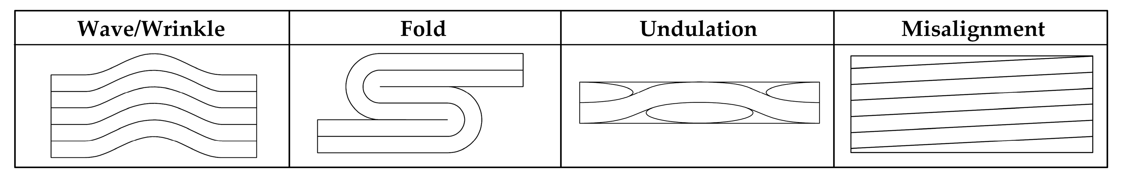
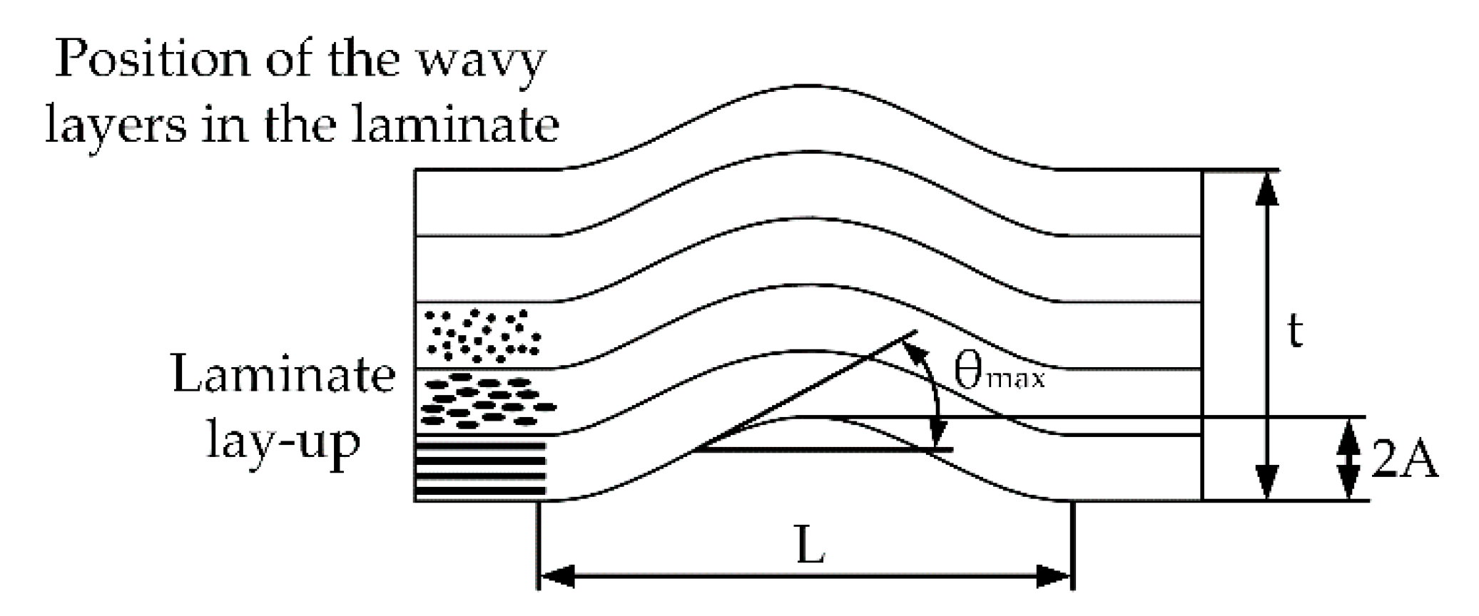
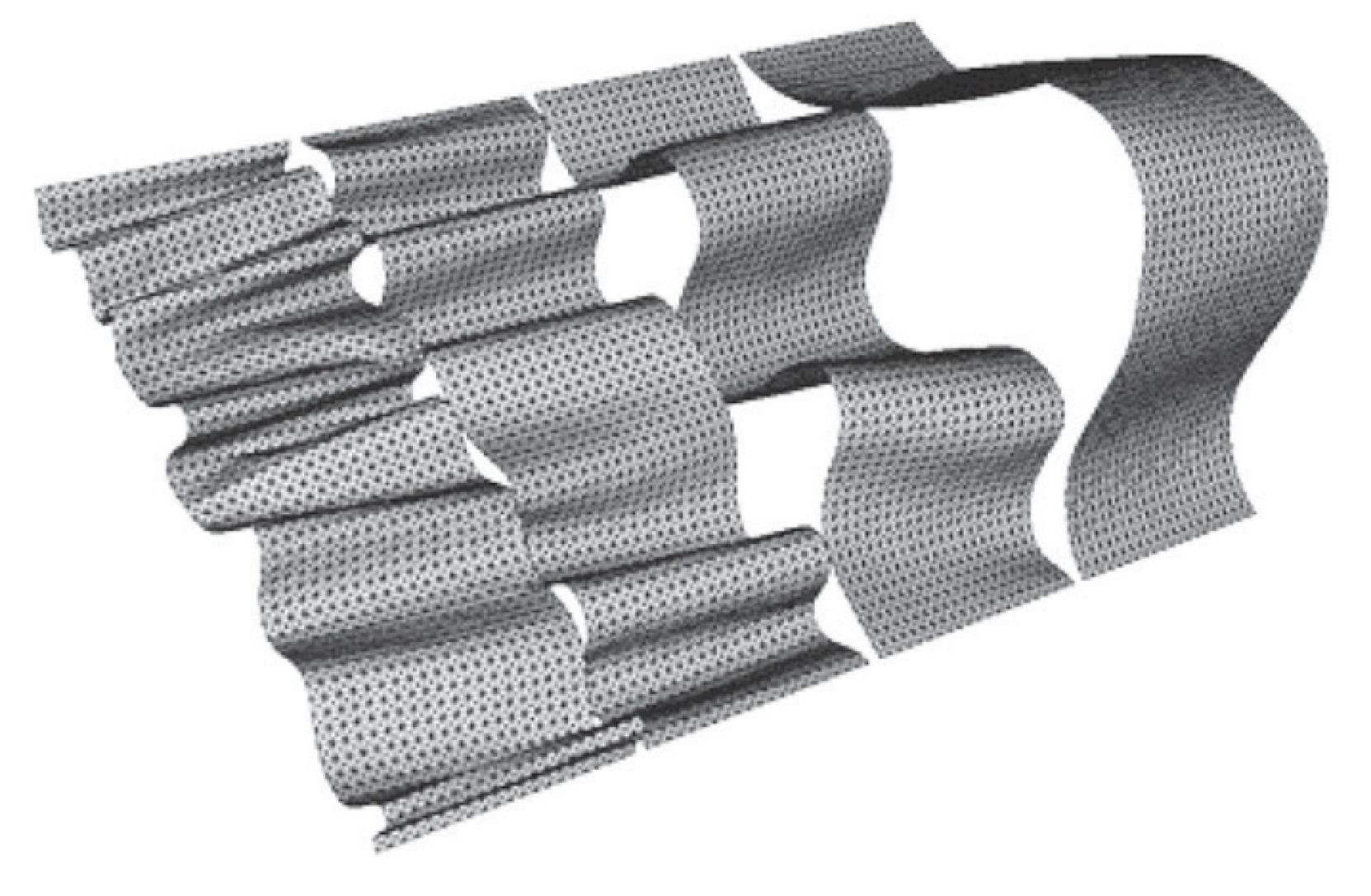
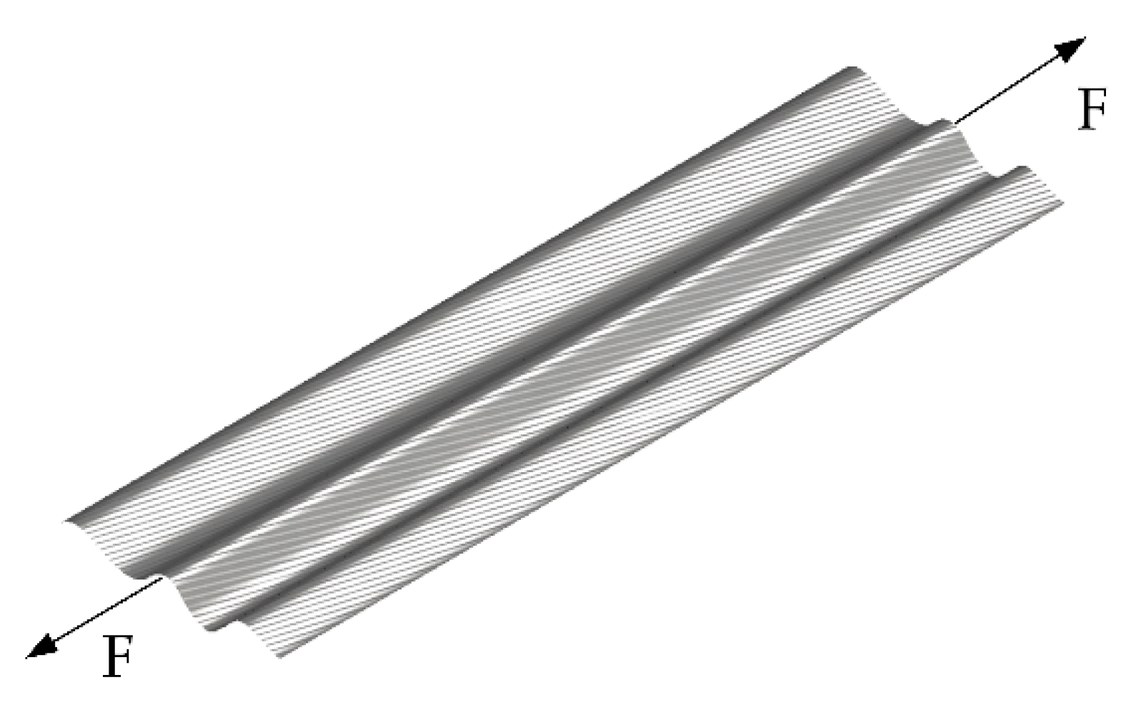
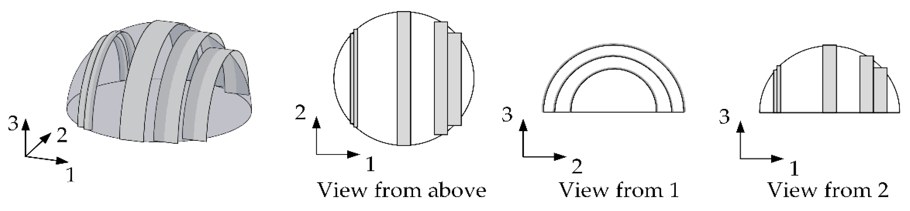
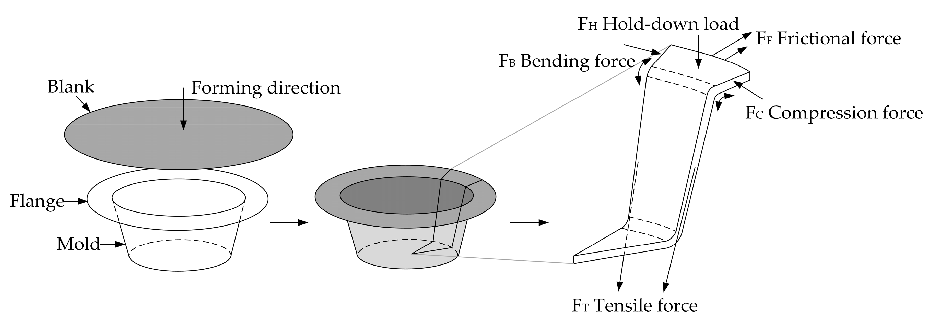
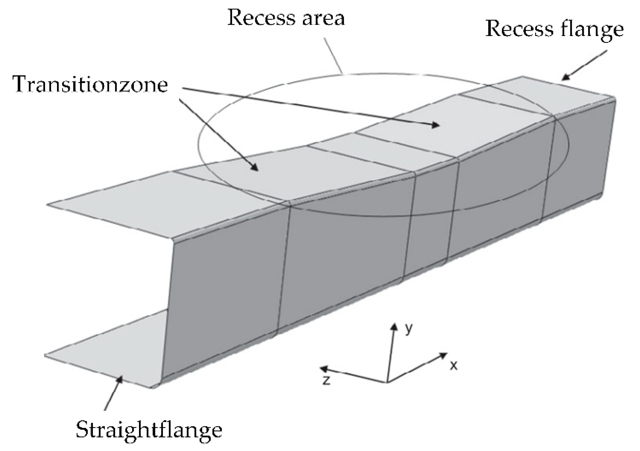
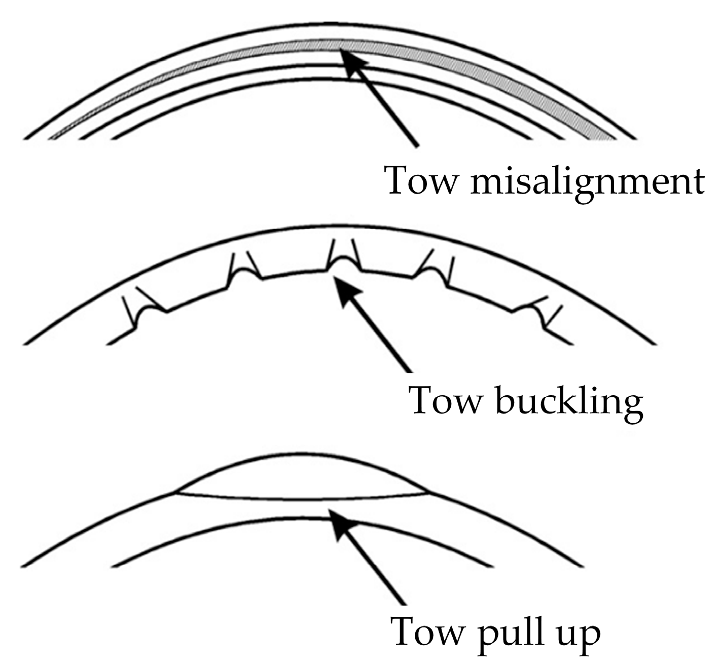
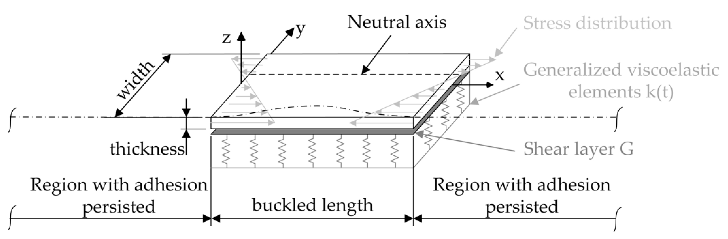
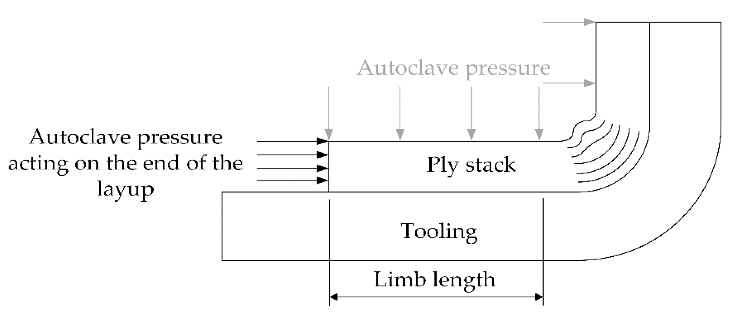
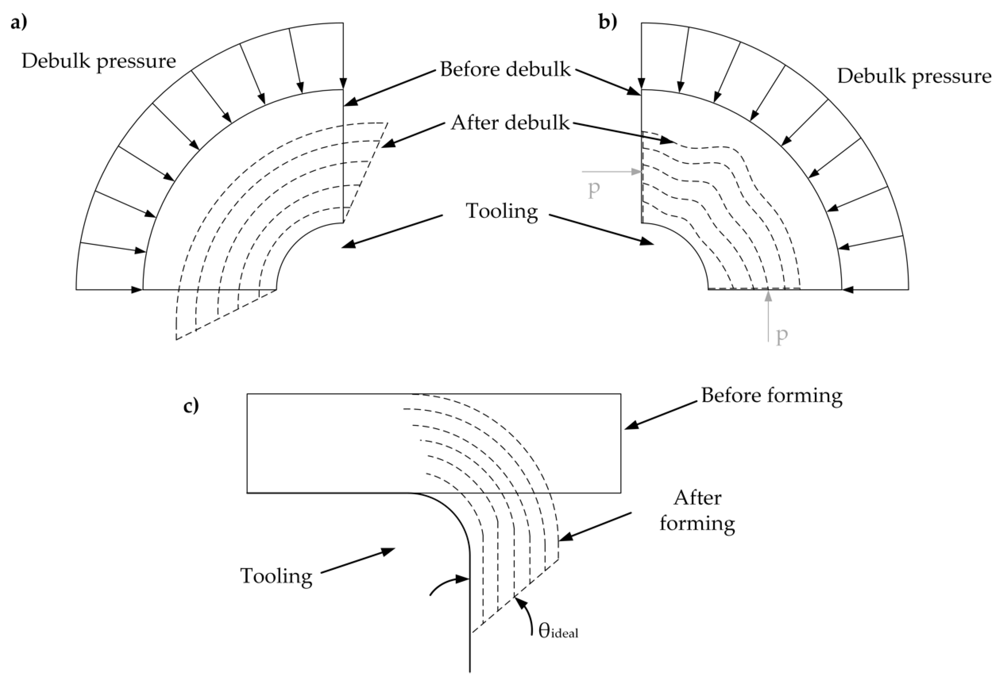
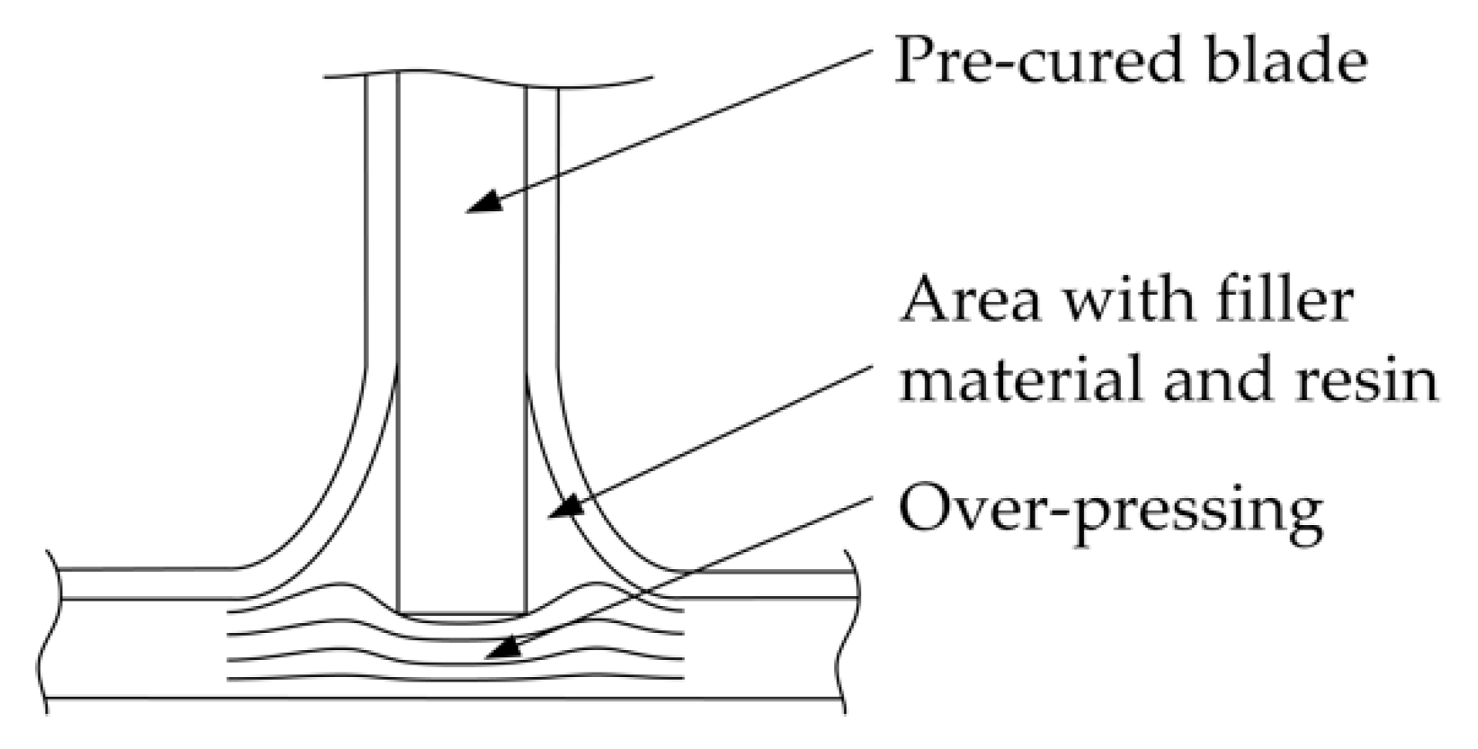
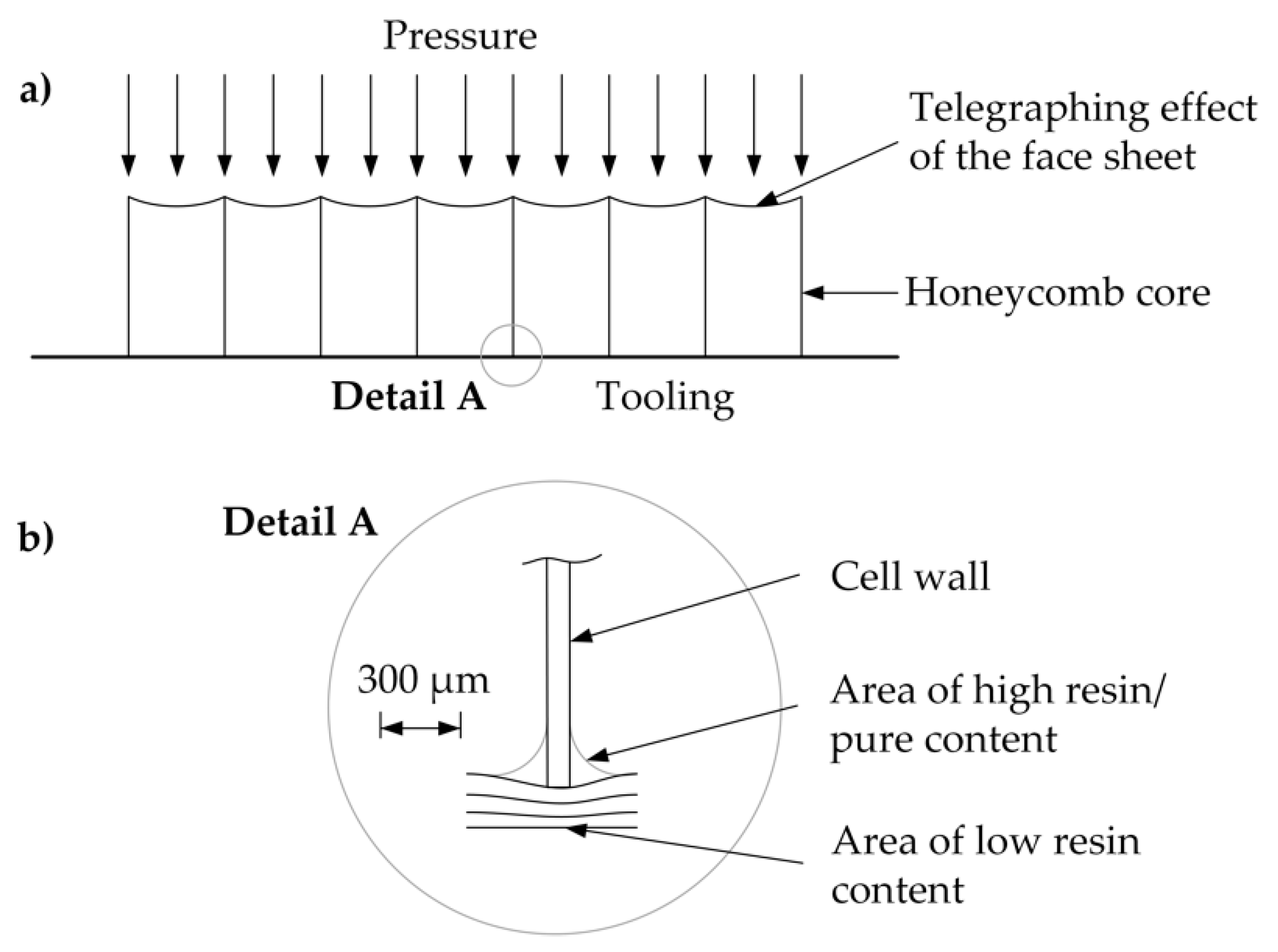
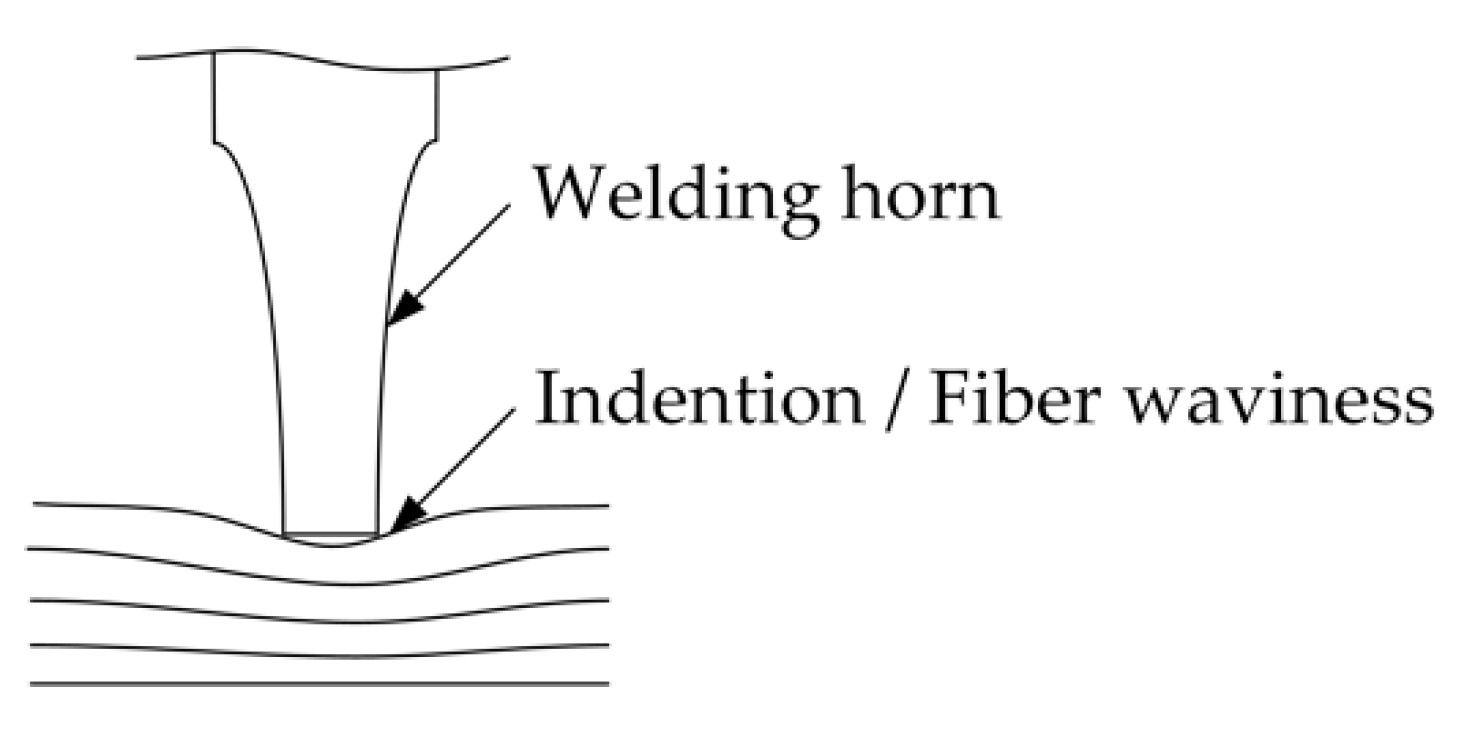
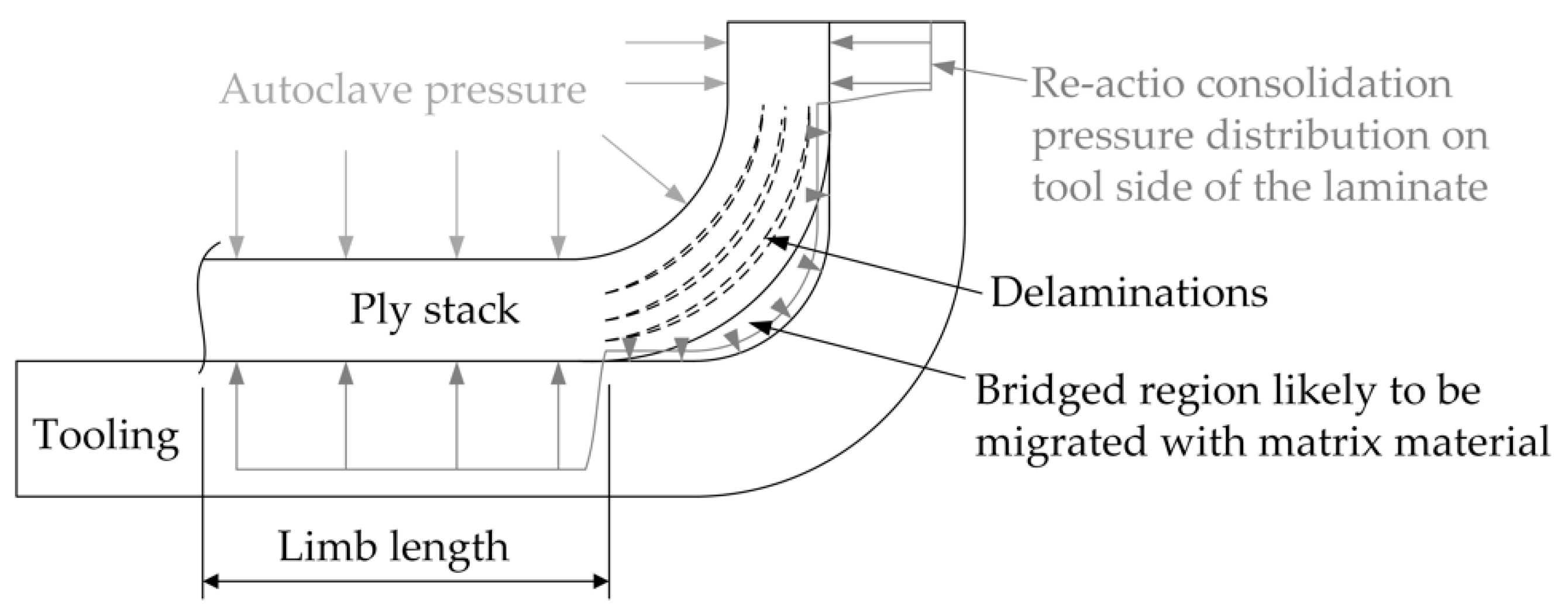
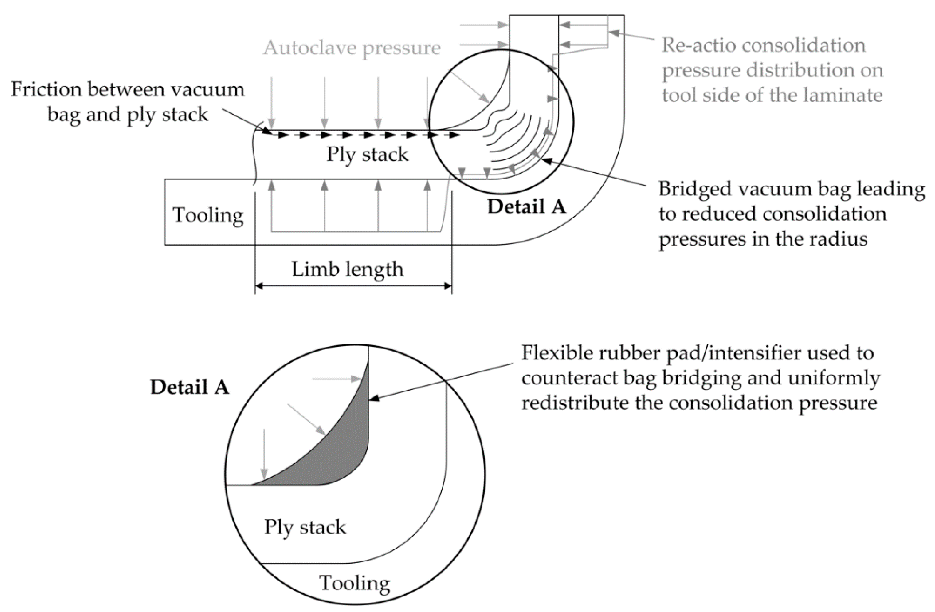
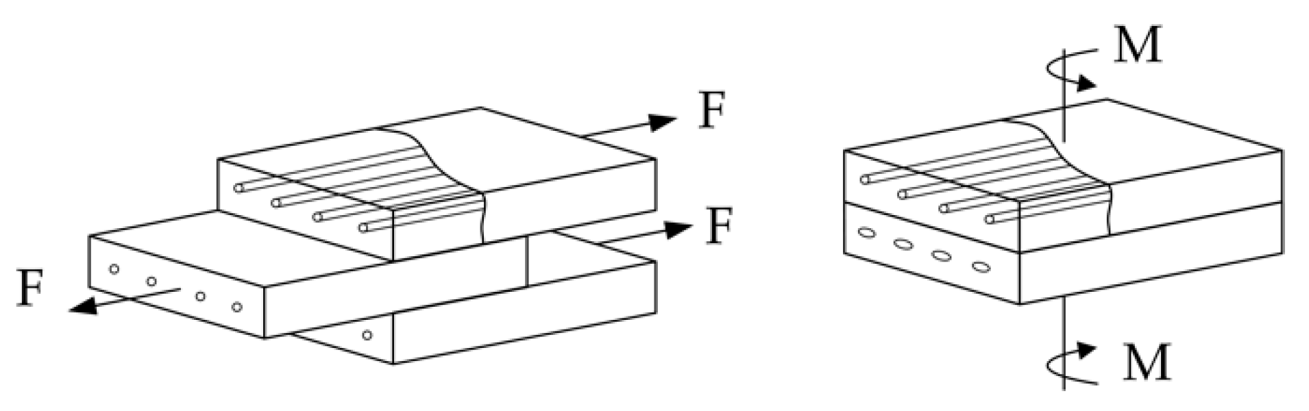
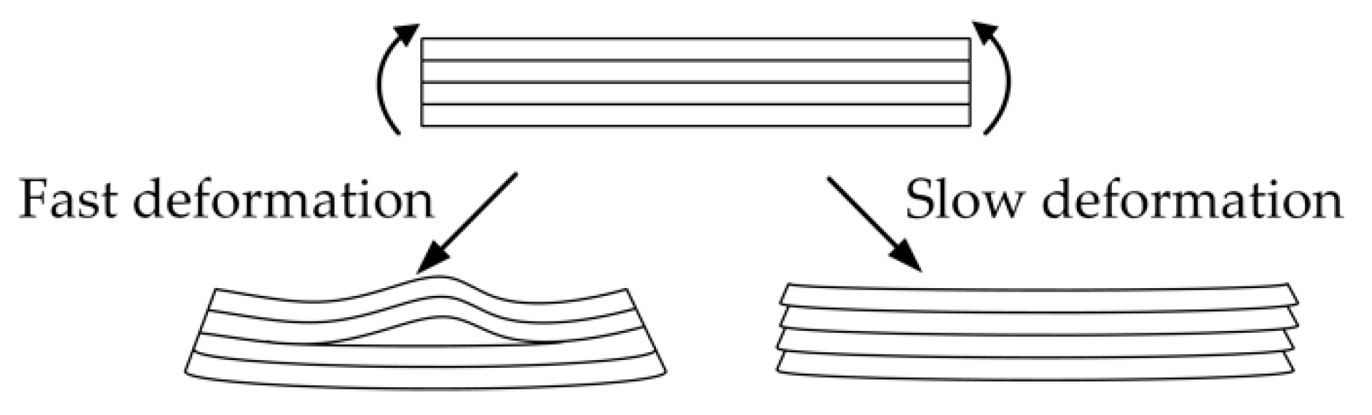
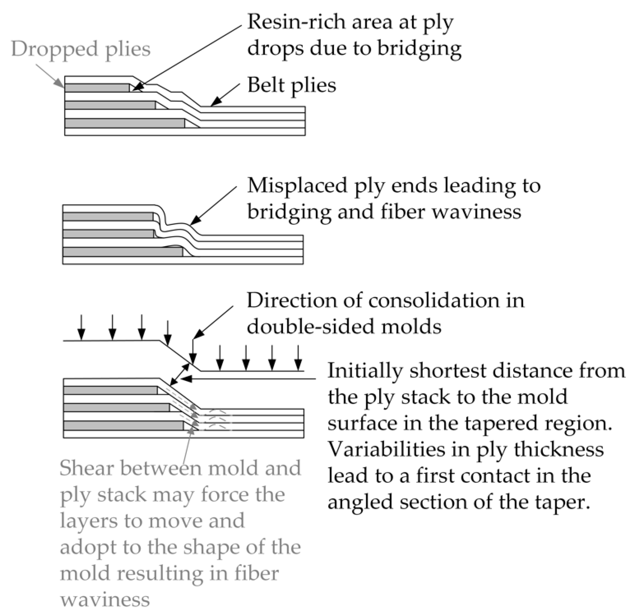
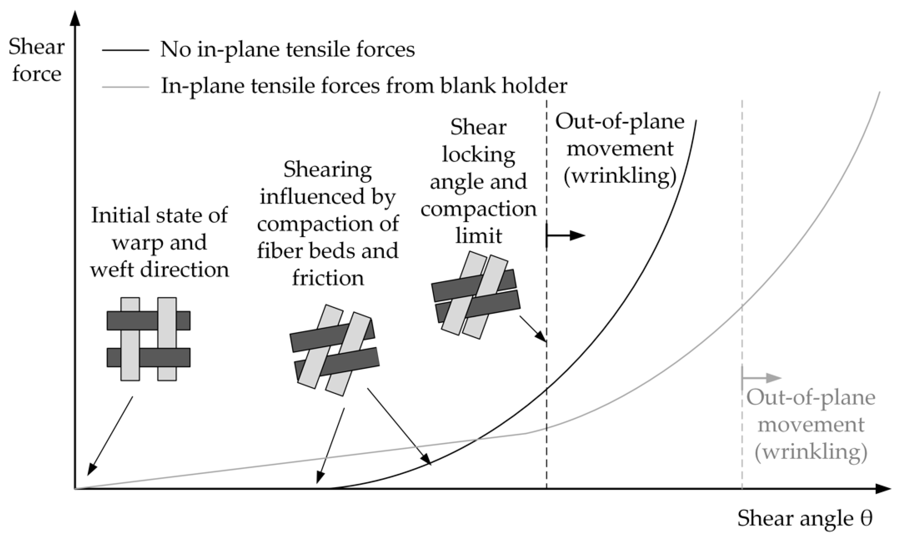
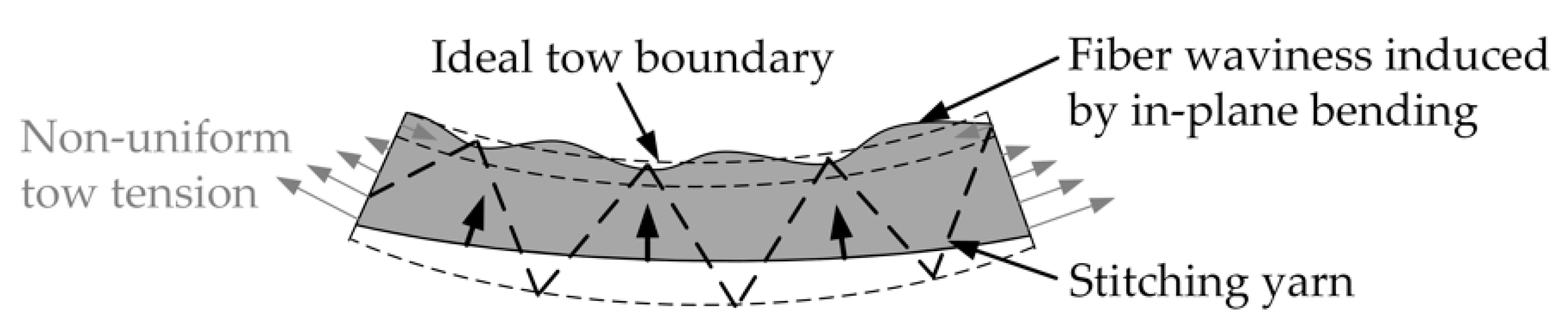
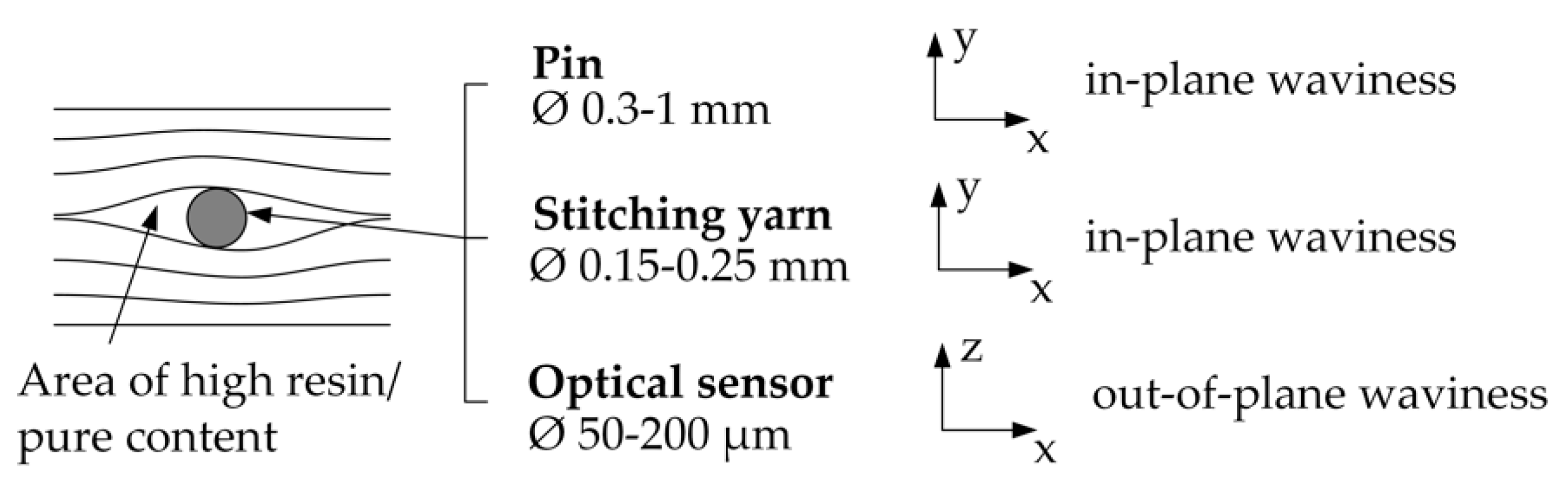
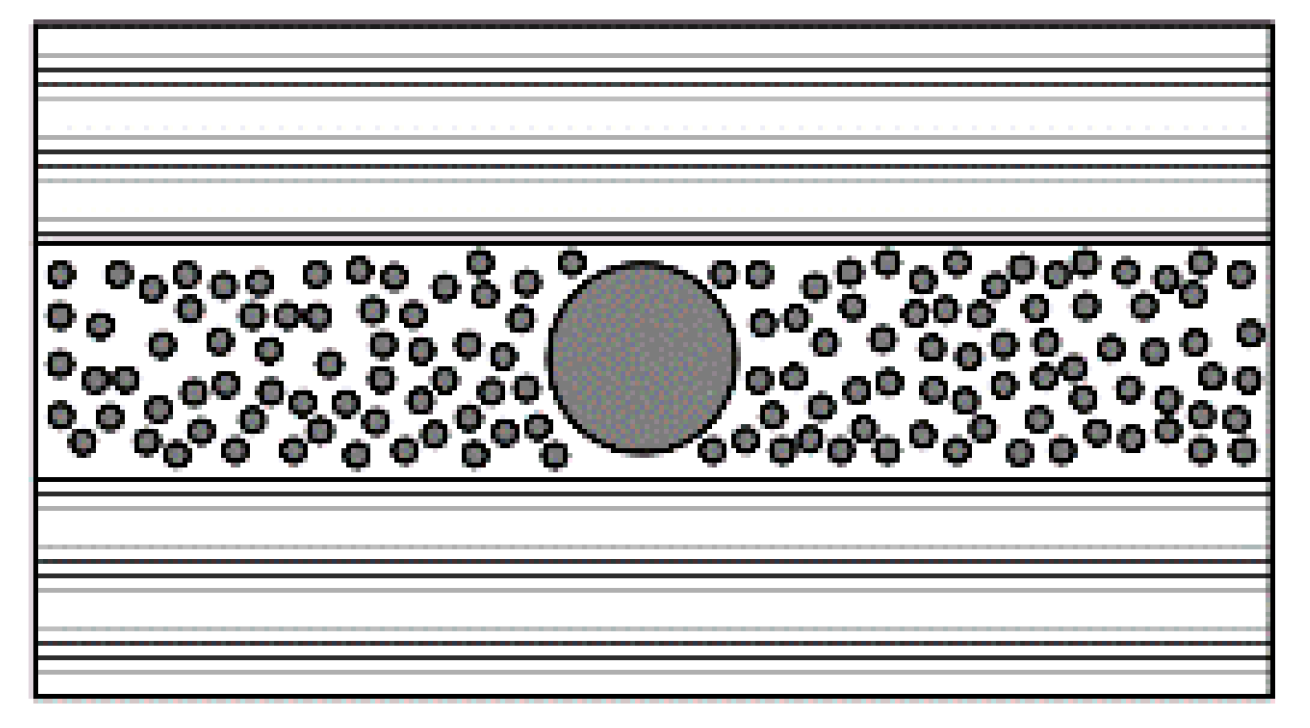
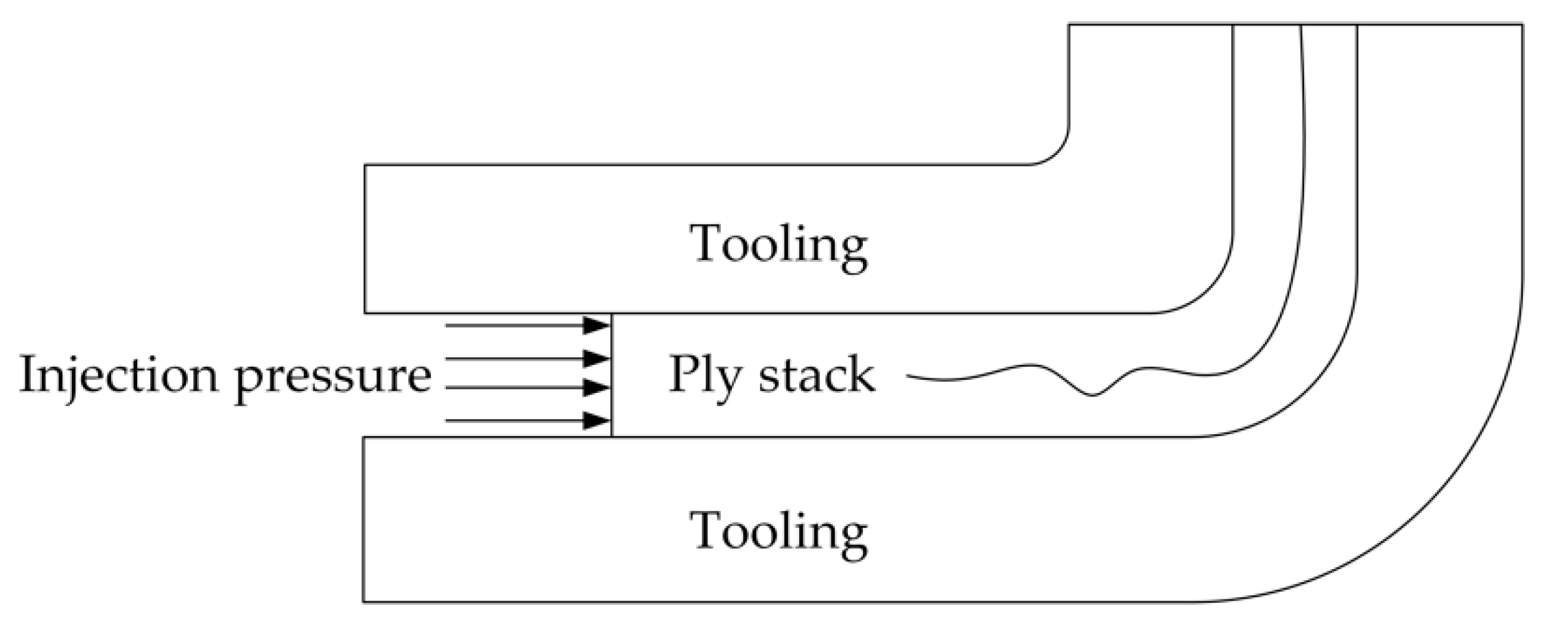
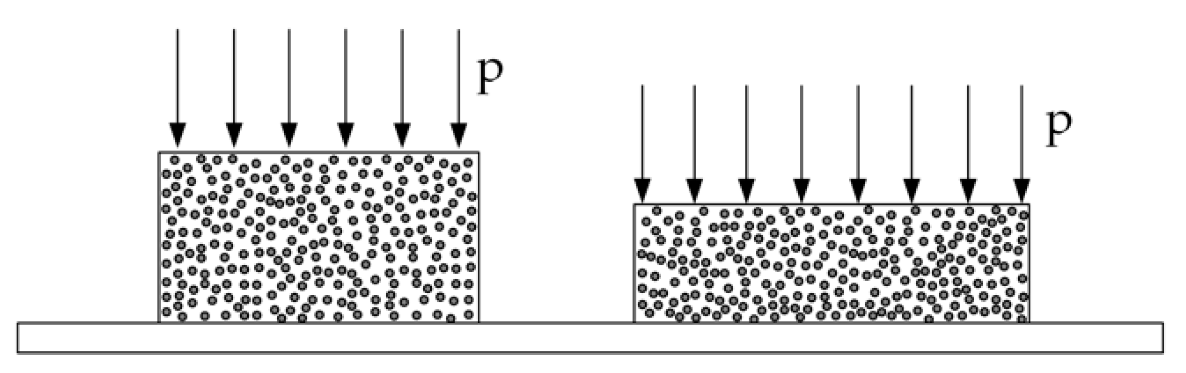
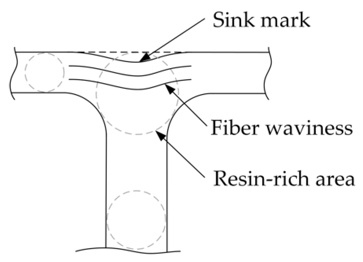
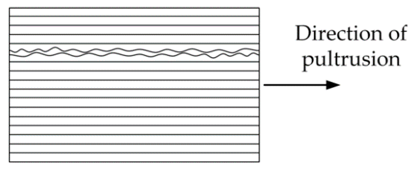
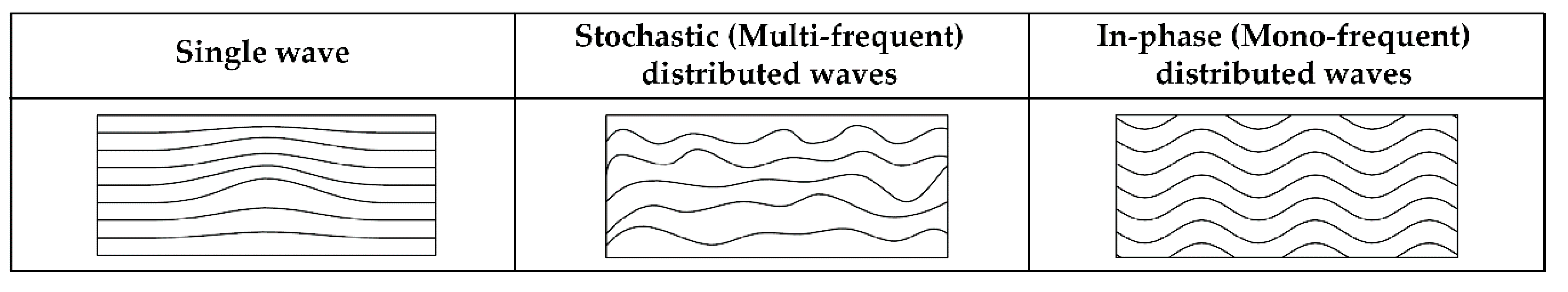
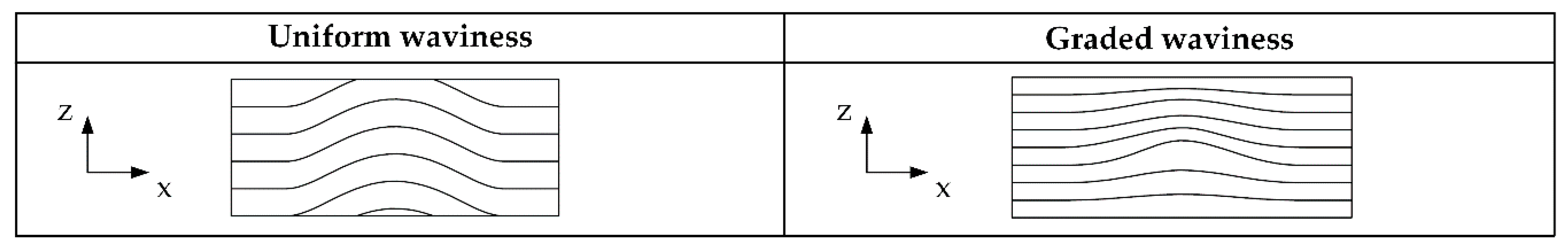
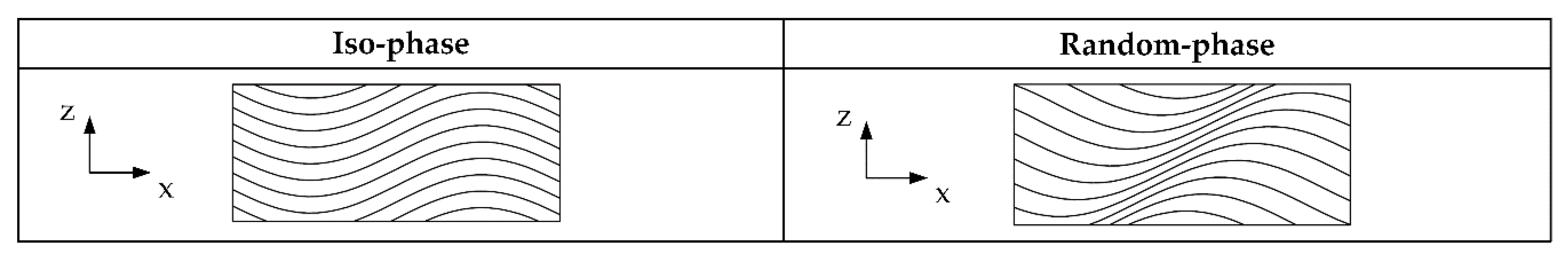
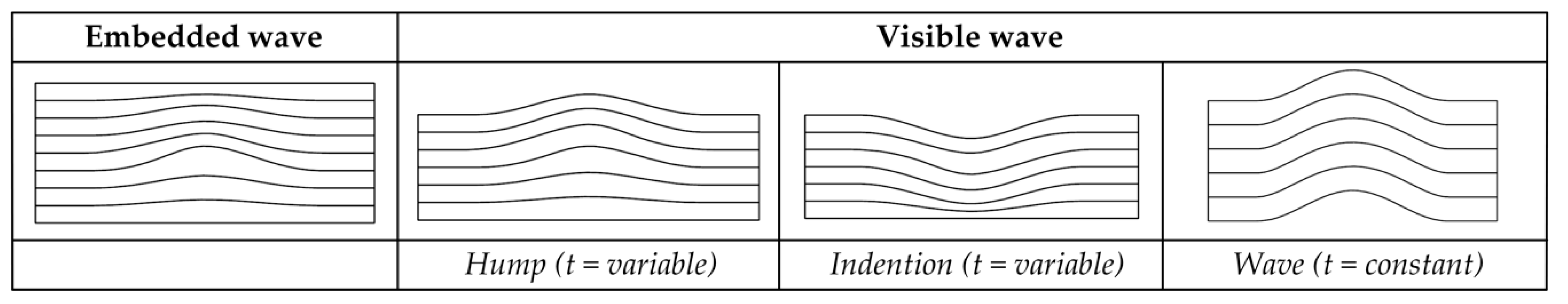
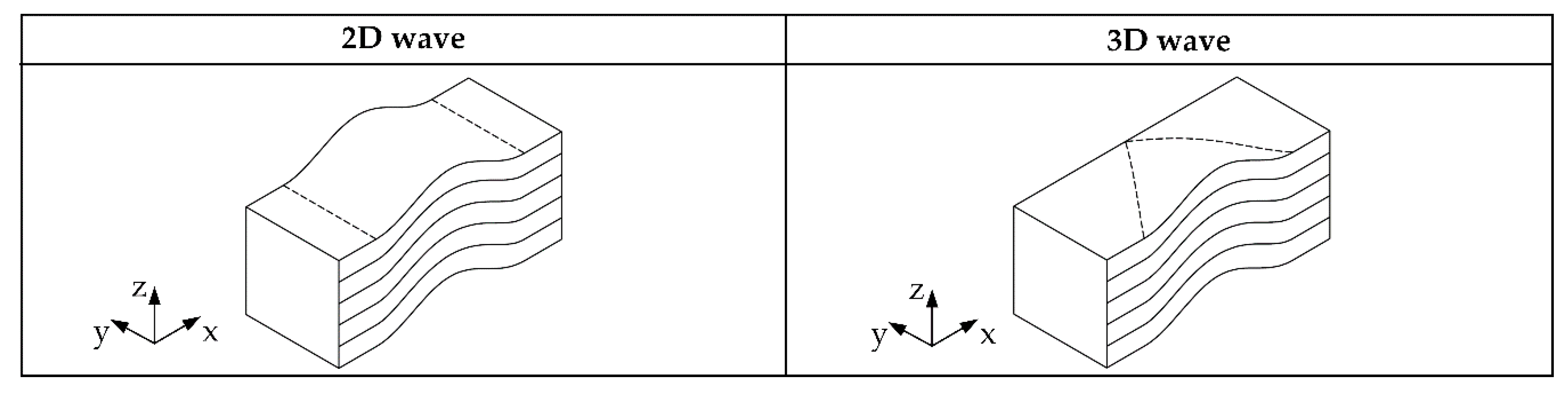
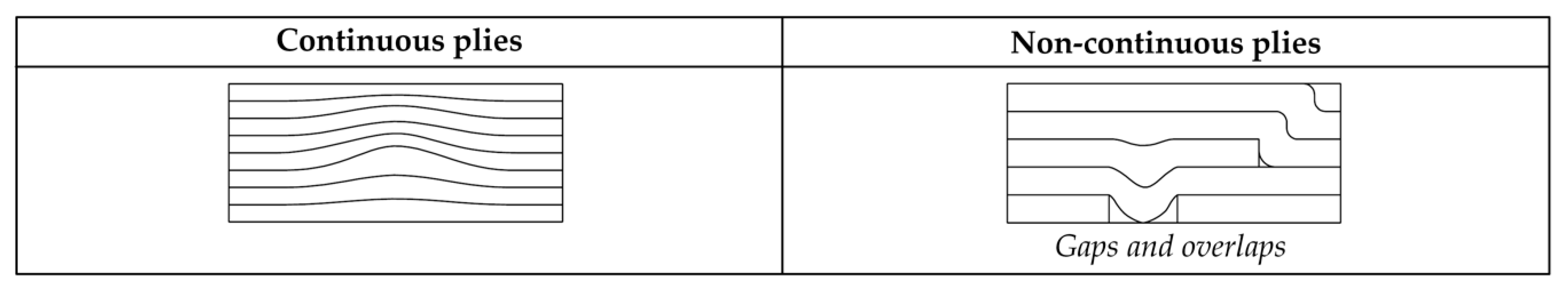
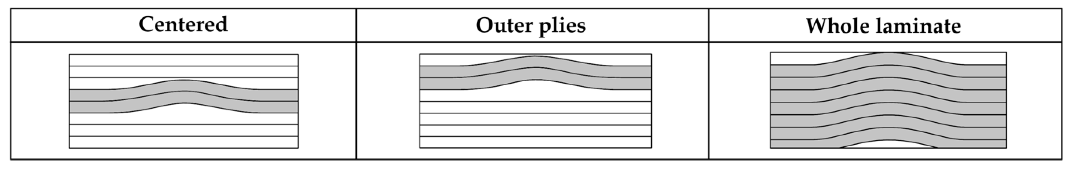
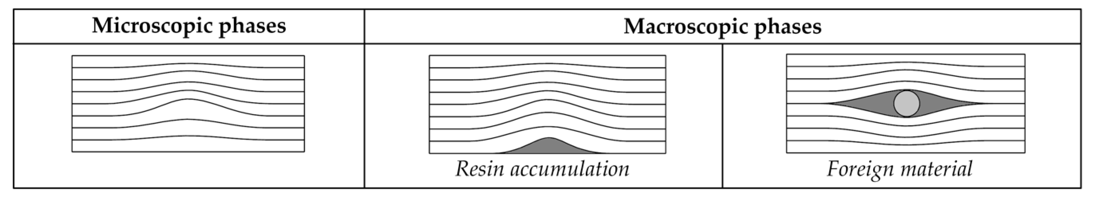
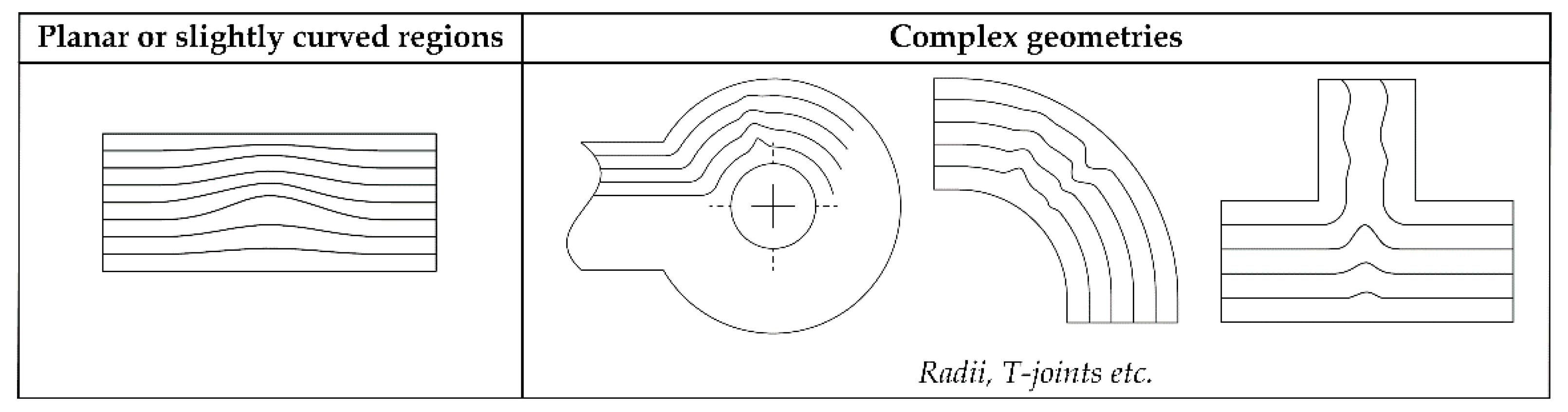
Table 1.
Variation of minimum steering radius with slit-tape width for a 102 mm track width [50].
Table 1.
Variation of minimum steering radius with slit-tape width for a 102 mm track width [50].
| Slit-Tape Width | Typical Minimum Steering Radius |
|---|---|
| 3.175 mm 1/8″ | 635.0 mm 25″ |
| 6.350 mm 1/4″ | 1778 mm 70″ |
| 12.70 mm 1/2″ | 8890 mm 350″ |
Table 2.
Typical coefficients of thermal expansion for composite materials and metals.
| Material | Coefficient of Thermal Expansion [10−6/°C] | |
|---|---|---|
| CFR-Epoxy—UD longitudinal | 0.3 | [92,93] |
| CFR-Epoxy—UD transverse | 35 | [92,93] |
| CFR-PEEK—UD longitudinal | 0.4 (23–143 °C)—solid state 0 (143–343 °C)—rubbery region | [94] |
| CFR-PEEK—UD transverse | 30 (23–143 °C)—solid state 80 (143–343 °C)—rubbery region | [94] |
| CFR-PEEK—quasi isotropic | 2.9 (23–143 °C)—solid state 7 (143–343 °C)—rubbery region | [94] |
| Neat epoxy resin | 55–76 | [92,95,96] |
| Carbon fiber—longitudinal | −0.4–−0.75 (High strength—high modulus fibers) | [80,96] |
| Carbon fiber—transverse | 8 | [96] |
| Glass fiber | 5 | [80,95] |
| Aluminum | 12–25 | [80,97] |
| Steel | 7–12 | [80,92] |
CFR-Epoxy: Carbon fiber reinforced epoxy; UD: unidirectional; CFR-PEEK: Carbon fiber reinforced polyether ether ketone.
Table 3.
Examples for waviness classification.
| Example of Fiber Waviness | Number and Distribution (Single, Stochastic or In-Phase Distributed) | Through-Thickness Wave Form (Uniform vs. Graded) | Phase Characteristics of the Wave Form (Iso-Phase, Random-Phase) | Visibility (Embedded, Hump, Indention, Wave) | Dimensional Characteristics (2D, 3D) | Continuity of Layers/Laminate (Continuous, Non-Continuous) | Position (Centered, Outer Plies, Whole Laminate) | Phase Characteristics (Microscopic, Macroscopic) | Level of Influence (Material, Structure) | Geometric Position (Flat or Slightly Curved Areas, Complex Geometries) |
|---|---|---|---|---|---|---|---|---|---|---|
 | Single | Uniform | Iso-phase | Wave | 2D | Continuous | Whole laminate | Microscopic | Structural | Flat |
 | Single | Graded | Iso-phase | Embedded | 2D | Continuous | Whole laminate | Microscopic | Material | Flat |
 [162] | Stochastic distributed | Graded | Random-phase | Embedded | 3D | Non-continuous | Whole laminate | Microscopic | Material | T-joint |
 [11] | Single | Graded | Iso-phase | Hump | 2D | Continuous | Whole laminate | Macroscopic | Material | Flat |
© 2020 by the authors. Licensee MDPI, Basel, Switzerland. This article is an open access article distributed under the terms and conditions of the Creative Commons Attribution (CC BY) license (http://creativecommons.org/licenses/by/4.0/).
Share and Cite
MDPI and ACS Style
Thor, M.; Sause, M.G.R.; Hinterhölzl, R.M. Mechanisms of Origin and Classification of Out-of-Plane Fiber Waviness in Composite Materials—A Review. J. Compos. Sci. 2020, 4, 130. https://0-doi-org.brum.beds.ac.uk/10.3390/jcs4030130
AMA Style
Thor M, Sause MGR, Hinterhölzl RM. Mechanisms of Origin and Classification of Out-of-Plane Fiber Waviness in Composite Materials—A Review. Journal of Composites Science. 2020; 4(3):130. https://0-doi-org.brum.beds.ac.uk/10.3390/jcs4030130
Chicago/Turabian StyleThor, Michael, Markus G. R. Sause, and Roland M. Hinterhölzl. 2020. "Mechanisms of Origin and Classification of Out-of-Plane Fiber Waviness in Composite Materials—A Review" Journal of Composites Science 4, no. 3: 130. https://0-doi-org.brum.beds.ac.uk/10.3390/jcs4030130