Article

Damage Detection in Glass/Epoxy Laminated Composite Plates Using Modal Curvature for Structural Health Monitoring Applications

by
Mahendran Govindasamy
1,*,
Gopalakrishnan Kamalakannan
1,
Chandrasekaran Kesavan
1 and
Ganesh Kumar Meenashisundaram
2,*
1
Department of Mechanical Engineering, RMK Engineering College, RSM Nagar, Kavaraipettai, Tamil Nadu 601206, India
2
Singapore Institute of Manufacturing Technology, 73 Nanyang Drive, Singapore 637662, Singapore
*
Authors to whom correspondence should be addressed.
J. Compos. Sci. 2020, 4(4), 185; https://0-doi-org.brum.beds.ac.uk/10.3390/jcs4040185
Submission received: 9 September 2020 / Revised: 8 December 2020 / Accepted: 9 December 2020 / Published: 14 December 2020
(This article belongs to the Special Issue Characterization and Modelling of Composites)

Abstract

:
This paper deals with detection of macro-level crack type damage in rectangular E-Glass fiber/Epoxy resin (LY556) laminated composite plates using modal analysis. Composite plate-like structures are widely found in aerospace and automotive structural applications which are susceptible to damages. The formation of cracks in a structure that undergoes vibration may lead to catastrophic events such as structural failure, thus detection of such occurrences is considered necessary. In this research, a novel technique called as node-releasing technique in Finite Element Analysis (FEA), which was not attempted by the earlier researchers, is used to model the perpendicular cracks (the type of damage mostly considered in all the pioneering research works) and also slant cracks (a new type of damage considered in the present work) of various depths and lengths for Unidirectional Laminate (UDL) ( [ 0 ] S and [ 45 ] S ) composite layered configurations using commercial FE code Ansys, thus simulating the actual damage scenario. Another novelty of the present work is that the crack is modeled with partial depth along the thickness of the plate, instead of the through the thickness crack which has been of major focus in the literature so far, in order to include the possibility of existence of the crack up to certain layers in the laminated composite structures. The experimental modal analysis is carried out to validate the numerical model. Using central difference approximation method, the modal curvature is determined from the displacement mode shapes which are obtained via finite element analysis. The damage indicators investigated in this paper are Normalized Curvature Damage Factor (NCDF) and modal strain energy-based methods such as Strain Energy Difference (SED) and Damage Index (DI). It is concluded that, all the three damage detection algorithms detect the transverse crack clearly. In addition, the damage indicator NCDF seems to be more effective than the other two, particularly when the detection is for damage inclined to the longitudinal axis of the plate. The proposed method will provide the base data for implementing online structural health monitoring of structures using technologies such as Machine Learning, Artificial Intelligence, etc.

1. Introduction

In high-speed mechanical applications such as turbomachinery and aerospace structures, there is a pressing need for high strength lightweight materials. The usage of non-homogenous fiber reinforced composites has increased widely due to its tailorable direction-dependent properties, high stiffness and increased corrosion resistance. However, composites are susceptible to unnoticeable damages as they experience various loading conditions in-service such as fatigue, bird impacts, lightning strikes etc. which can alter its dynamic characteristics ultimately leading to failure [1]. Some of the types of damages that occur in laminated composites are delamination, fiber-matrix debonding, matrix cracking, inter-laminar failure and fiber breakage [2].
Most of the non-destructive testing (NDT) methods for detecting damage in structures may be characterised as either local or global methods. In the past, researchers studied various local non-destructive techniques for damage detection in composites like X-Ray [3], microwave [4], acoustic emission [5], infrared thermography [6], ultrasonic [7] and magnetic-field methods [8]. Although these techniques hold some merits, it was reported that they were found to be somewhat difficult for applying in in the stuructures where the accessibility is very difficult like offshore oil platforms and the flying machines like aerospace vehicles as it require disassembly of parts and the locality of the damage is known prior to the testing which may be difficult in complex structures. In particular, the matrix cracks in composites lying perpendicular to the surface are hard to detect as most of the afore-mentioned methods require a wide enough reflecting surface which is the case in delamination type damages [9]. Thus, damage detection technique which is global in nature such as vibration-based methods may be found more useful, individually or in combination with other local methods, for successful non-destructive evaluation of laminated composite structures.
The fundamental basis of such a technique is based on the fact that, the changes in the structure’s inherent parameters such as mass, stiffness and damping reflect in its modal properties such as natural frequency, mode shape and modal damping respectively [10]. In the past few decades, there has been substantial research carried out in the field of vibration-based damage detection across the world. Dimarogonas [11] has contributed a review of the studies carried out on cracked structures such as beams, plates and shells until 1996. This paper provided an excellent overview of the scope of crack study in plate-like structures and highlighted the topics of interest for future research. In their respective summary reviews of various vibration-based methods for damage detection, Doebling et al. [12] focussed on structural and mechanical systems, and Wei Fan [13] emphasized on algorithms and signal processing methods. The reduction in natural frequency is considered as an easily observable change which has been explored by researchers in the past. The determination of crack location in varying-cross section slender beams using natural frequencies was investigated by Chinchalkar [14]. A description of a numerical-based finite element approach was made and the results obtained in the past through semi-analytical approach using Frobenius method are compared with the current. The proposed method had an advantage which allowed to model different depths and boundary conditions of the beam. However, its limitation lays in the fact that in case of large-sized damages, slight change in the natural frequencies may be observed which may go unnoticed.
Some of the authors investigated the displacement mode shape [15] and its rotation [16] as damage indicators from dynamic behaviour of beam and plate structures respectively. It was stated that, the former was less sensitive and localized to damage than the latter. In addition, when the damage was in proximity to the node point, the displacement shape showed very little change in comparison with that of intact structure. On the contrary, the first order derivative of the mode shapes highlighted damages of various sizes at multiple locations within the structure. Nevertheless, there are some drawbacks for considering mode shapes for damage detection. Firstly, the vibration testing carried out for large structures usually considers lower fundamental modes and its corresponding mode shapes may not be affected significantly due to damage. Secondly, the number of sensors placed on the structure and noise effects play a very important role in the damage diagnosis procedure.
Pandey et al. [17] investigated a novel parameter called Curvature Mode Shape (CMS) for identification and localization of damages in structures. A cantilever and simply supported beam models were used and the results exhibited that the modal curvature was localized at damage location. Lestari et al. [18] have applied curvature mode shape as a damage indicator for carbon/epoxy laminated composite beam with an assumed damage effect in the form of stiffness loss in the analytical model for the damaged structure. The discontinuities in the modal curvature due to the presence of damage have been observed in the numerical simulation and with the use of surface-bonded Polyvinylidene fluoride (PVDF) film as sensors, the curvature modes have been measured experimentally. However, for higher modes, the modal curvature showed peaks at locations other than the damage which may lead to misinterpretation of results. Abdel Wahab et al. [19] applied the method of changes in curvature mode shapes for damage localization in simply supported and continuous beam models using finite element simulation and to a real-time measured data obtained from pre-stressed Z24 concrete bridge. An attempt has been made to minimize the misleading peaks by an indicator called as Curvature Damage Factor (CDF) and concluded that it functioned to a certain extent, though not completely. Hence, to improve the accuracy of damage detection, an indicator called NCDF (Normalized Curvature Damage Factor) has been utilized by Lu et al. [20] for identification of crack in beam structures. Qiao et al. [18] carried out numerical and experimental modal analysis to determine curvature mode shape for detection, localization and quantification of delamination in laminated composite plates. It was stated that, the dynamic response data measured experimentally cannot be readily used for detection of damage and are often used in conjunction with damage detection algorithms. The Gapped Smoothing Method (GSM), Generalized Fractal Dimension (GFD) and Strain Energy Method (SEM) were the algorithms used to analyse the modal curvature data and concluded that, the GSM located delamination better than GFD and SEM which showed extra peaks at locations other than the damage.
Cornwell et al. [21] extended the application of strain energy method to plate-like structures which was initially developed for one-dimensional beam structures. They established a damage detection algorithm called Damage Index Method (DIM) based on modal strain energy and concluded that, it was successful in detecting damages in areas up to 10% reduction in stiffness value. Huiwen Hu et al. [22] presented an approach based on strain energy to detect surface crack type damage in carbon/epoxy composite laminated plate for four different layups. A combination of experimental and numerical methods was used to determine the mode shapes for calculating strain energies based on Differential Quadrature Method (DQM). They concluded that, the developed damage index successfully identified the presence of damage and required only a few mode shapes before and after damage. Wang et al. [23] investigated the modal characteristics of damaged laminated composite plates using analytical and numerical approaches. The degradation of stiffness of the structure was considered as damage and concluded that, the modal strain energy and curvature mode shape had higher sensitivity to damage than natural frequencies and displacement mode shapes. The effect of damage in a structure had been modelled through various methods previously. Many researchers have considered the damage to be a reduction in the elemental Young’s modulus in numerical finite element model or reduction in the second moment of area of cross-section or modeled the crack as a V-shaped groove by considering a solid element in finite element modelling as summarised in Table 1.
From the above table it is clearly evident that most of the pioneering researches focus on damage detection in homogenous isotropic beam structures and a few in the recent past on laminated beam and plate like structures using the above-mentioned crack modelling techniques. However, there has not been much work on using the changes in curvature mode shapes for such detection purposes, especially using the proposed node releasing technique in laminated plates. In all the above research works the damage was considered as through the thickness perpendicular cracks and no research work has been carried out to detect damage in laminated structures by considering the damage running through partial thickness and also the slant cracks. Hence the present work concentrates on damage detection in laminated composite rectangular plates with variable sized damages (both perpendicular and slant cracks) using modal analysis through Finite Element Analysis (FEA). The FEA is carried out using the Ansys Parametric Design Language (APDL) code. A sample of the code developed to model the crack using the node releasing technique and do modal analysis of the laminated plate is given in the Annexure. The proposed method will provide the base data for implementing online structural health monitoring of structures using the technologies such as Machine Learning and Artificial Intelligence etc with the support of higher efficiency sensors as suggested by Zengshun Chen et al. [51]. The modal behaviour of a cracked glass/epoxy composite plate is examined considering fundamental bending modes only. A numerical investigation is carried out to determine the presence of crack and its location through a linear approach based on changes in modal curvature. Furthermore, to validate the numerical model, the experimental modal analysis is carried out on intact and cracked composite plate specimens. The previous researchers mostly considered transverse through thickness cracks only and detection of partial thickness damage in laminated composite structures is scarce. In this paper, the single edge non-propagating open crack damage is modelled by the technique of releasing nodes at damage location for various crack lengths and depths. Extensive parametric studies are required to establish a reliable damage detection algorithm capable of detecting crack type damage in composite plate structures. Two different orientations viz. transverse and angular partial depth cracks are studied to investigate the effectiveness of three damage detection algorithms namely NCDF, Strain Energy Difference (SED) and DIM.

2. Materials and Methods

2.1. Theoretical Background

2.1.1. Vibration of Laminated Composite Plate

The geometrical view of the rectangular laminated composite plate structure is shown in the Figure 1.
The notations of the length, width and height of the plate are L , W and h , L c is the location of the crack from the fixed end, a and b are the crack depth and length respectively. The equilibrium differential equation for a free vibrating laminated composite plate is [48]
2 M X X 2 +   2 M Y Y 2 + 2 2 M X Y X Y + N X 2 W X 2 +   N Y 2 W Y 2 +   2 N X Y 2 W X Y =   ρ h 2 W t 2
where W is the displacement of the plate in the transverse direction (Z-axis), M X ,   M Y , M X Y and N X , N Y , N X Y are the moments and forces in the middle plane and ρ is the density of the plate.

2.1.2. Damage Detection Algorithms

The measured experimental or numerical dynamic response data such as natural frequencies and mode shapes are often accompanied with damage detection algorithms. This is because sometimes these data are not readily available for implementation in detecting damage. By the usage of algorithms, the useful data can be extracted thus neglecting external noise effects. The damage detection algorithms used in this study are highlighted below.

Curvature Damage Factor (CDF)

The second order derivative of mode shape known as the curvature mode shape was introduced by Pandey et al. [17] for detecting damage in beams which is defined by 1-d curvature. In the present work, the method is applied to a plate-like structure defined by 2-d curvature. The reduction in the bending stiffness of the structure is observed when a crack or other type of damage is introduced which will increase the magnitude of the curvature at the location of damage. By the usage of numerical approach known as the central difference approximation, the modal curvature can be obtained from the displacement mode shapes through finite element analysis as [20]
ϑ =   ϑ i + 1 2 ϑ i +   ϑ i 1 l e 2
where ϑ is the curvature, ϑ is the normalized mode shape, i is the node number and l e is the length of the element used in FE modelling. The absolute difference in the Curvature Mode Shape Difference (CMSD) is given by
Δ ϑ =   | ϑ ( d ) ϑ ( u ) |
where ϑ ( d ) and ϑ ( u ) are the curvature mode shapes of the damaged and undamaged plates respectively. The normalization of the above-mentioned parameter is carried out to obtain the Normalized Curvature Mode Shape Difference (NCMSD) as [10]
Δ ϑ =   [ 1 + Δ ϑ max ( Δ ϑ ) min ( Δ ϑ ) ] 2
The damage indicator in this method is simply a distinctive peak which appears in the plot of absolute difference in curvature. However, for higher modes, the peaks appeared at locations other than that of the damage. In order to minimize the misleading peaks, a parameter called Curvature Damage Factor (CDF) was proposed by [19], which is the average of the absolute differences in the modal curvature of the undamaged and damaged models. Mathematically, it can be expressed as
C D F i =   1 n   j = 1 n   | ϑ ( d ) ϑ ( u ) |
where j represents the mode number. Nevertheless, the above-mentioned parameter was still unsatisfactory in completely diminishing the effect of misleading peaks. Hence, to improve the accuracy of damage detection, an indicator called as NCDF (Normalized Curvature Damage Factor), which is the average of Normalized Curvature Mode Shape Difference (NCMSD) between intact and damaged structures of all modes of interest, has been used by [20]. It can be expressed as
N C D F i =   1 n   j = 1 n N C M S D i  

Modal Strain Energy-Damage Index Method (DIM)

The damage detection based on the changes in modal strain energy fraction was extended to plate-like structures by Cornwell et al. [21]. This is considered as an extension of curvature mode shape-based method since it exhibits a direct relation to modal curvature and it can be derived from the same for beam and plate structures [13]. It provides an essential early warning of damage in the structure even though the change in the response of the system caused by the damage is minimal. The total strain energy, U of the laminated composite plate during elastic deformation is given by [22]
U =   1 2   0 b 0 a [ D 11 ( 2 w x 2 ) 2 + D 22 ( 2 w y 2 ) 2 + 2 D 22 ( 2 w x 2 ) ( 2 w y 2 ) + 4 ( D 16 2 w x 2 + D 26 2 w y 2 ) 2 w x y + 4 D 66 ( 2 w x y ) 2 ] d x d y
where w is the displacement in the transverse (Z-direction), a is length, b is width of the plate and D i j is the flexural rigidity of the composite plate.
The theoretical basis of this method is that, if the primary location of the damage is at a sub-region, then the change in the fractional modal strain energy will be significant in that area and constant at the undamaged regions [49]. The strain energy associated with a sub-region in an undamaged plate for the k th mode is given by
U k , i j   =   1 2   y j y j + 1 x i x i + 1 [ D 11 ( 2 ϕ k x 2 ) 2 + D 22 ( 2 ϕ k y 2 ) 2 + 2 D 22 ( 2 ϕ k x 2 ) ( 2 ϕ k y 2 ) + 4 ( D 16 2 ϕ k x 2 + D 26 2 ϕ k y 2 ) 2 ϕ k x y + 4 D 66 ( 2 ϕ k x y ) 2 ] d x d y
where x i ,   x i + 1 and y j ,   y j + 1 represent the start and end points of the sub-region along the x and y axis respectively as shown in Figure 2.
Similar equations can be written for a damaged plate with displacement mode shapes, ϕ k * . The expression for fractal strain energy for an intact plate is given as
F k , i j =   U k , i j U k
Similarly, the fractal strain energy for a damaged plate with the mode shape ϕ k * is given by
F k , i j * =   U k , i j * U k *
where U k * and U k , i j * are the total and sub-regional strain energies of the damaged plate. By taking into consideration the measured fundamental mode shapes m , the damage index β i j in the sub-region is given by
β i j =   k = 1 m F k , i j * k = 1 m F k , i j
The normalization of the damage index is given as
Z i j =   β i j   β ¯ i j σ i j
where β ¯ i j and σ i j indicate mean and standard deviation of the damage index respectively.

Modal Strain Energy Difference (SED)

It is well known that a certain amount of strain energy is stored by a specific mode of vibration. The damage induced in a structure alters the stiffness, thus affecting the natural frequency and the displacement mode shape which are related to modal strain energy. The relation of strain energy with a particular mode shape is given as [18]
U i =   1 2 x k x k + 1 E I ( 2 ϕ k x 2 ) 2 d x =   1 2 x k x k + 1 E I ( ϑ ) 2 d x
It is also known that, the flexural stiffness of the structure and the curvature parameter in the strain energy equation are interrelated. Thus, the stiffness reduction due to damage results in the increase of the curvature. Therefore, for indicating the location of damage, the square of the curvature mode shape found in the strain energy Equation (13) can be considered logically. The parameter for damage D i by the concept of strain energy U i given by the proportionality to the square of the modal curvature is expressed as
D i   ( ϑ ) 2 =   ( 2 ϕ k x 2 ) 2
The damage indicator based on this method is defined as the absolute difference between the square of the modal curvature of undamaged and damaged structure given by
S E D =   | ϑ u n d a m a g e d ( x ) 2   ϑ d a m a g e d ( x ) 2 |

2.2. Numerical Modal Analysis

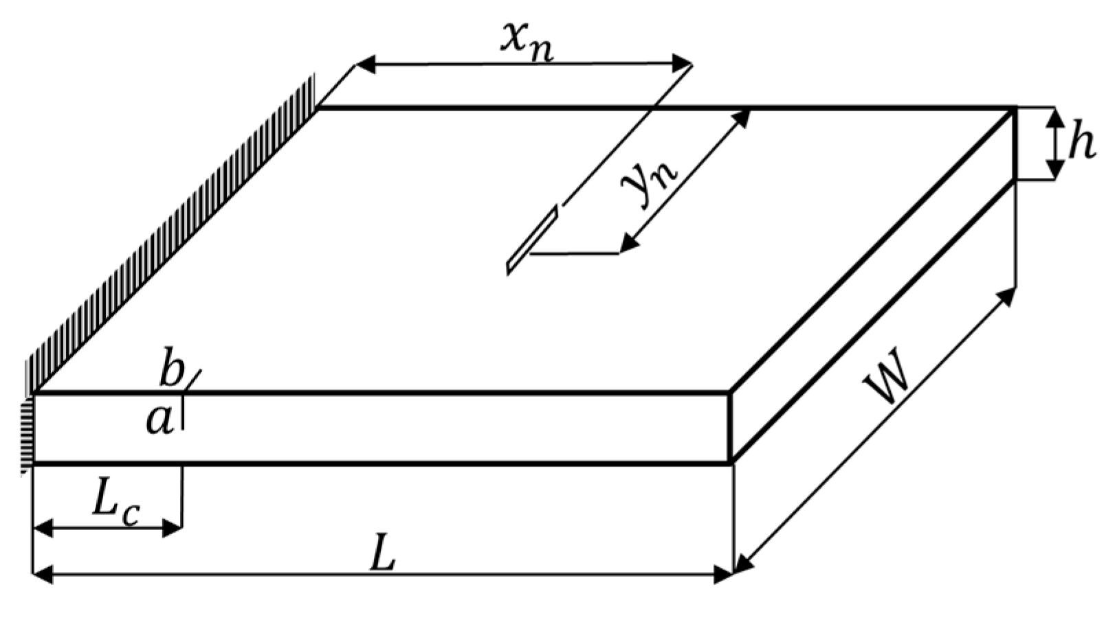
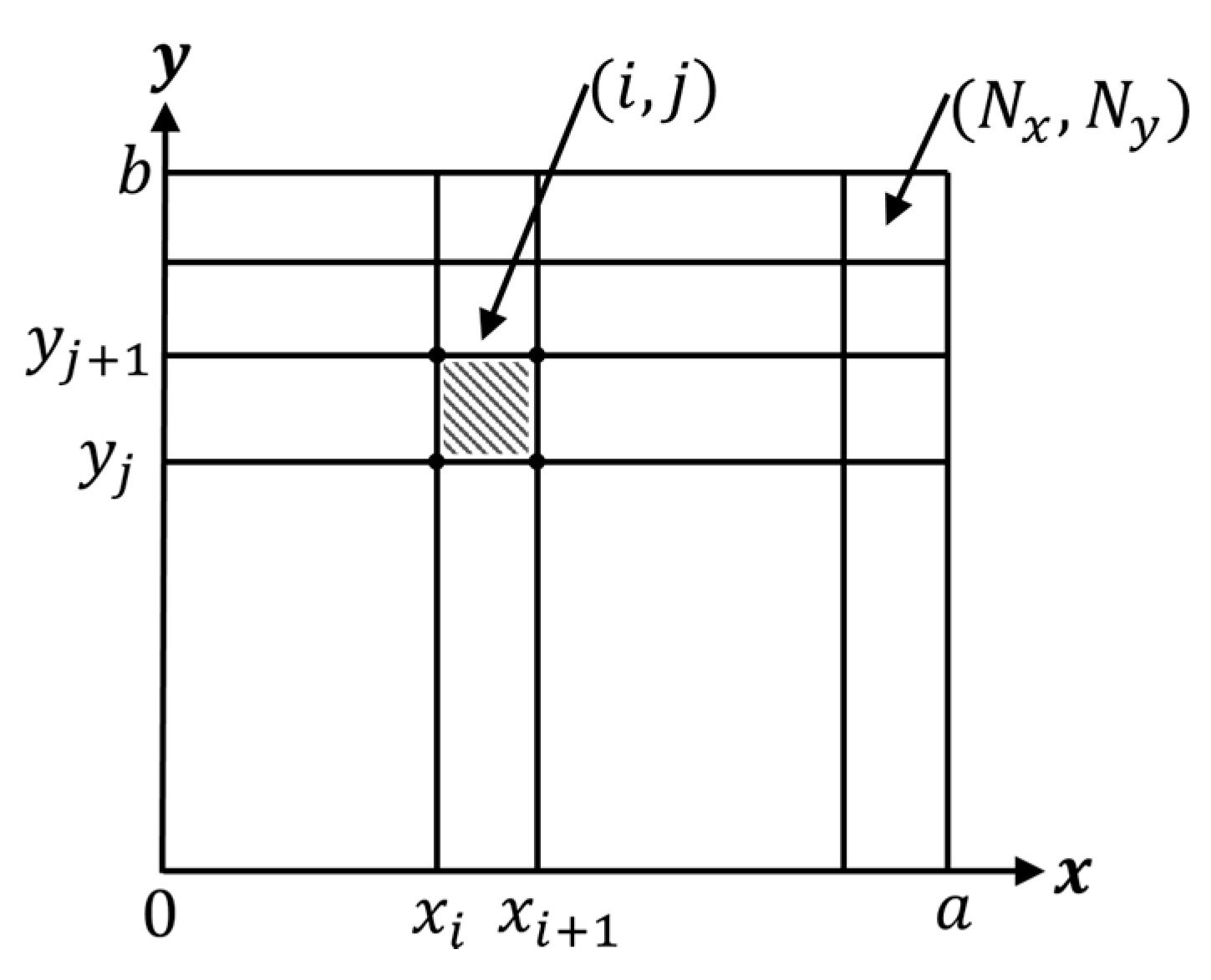
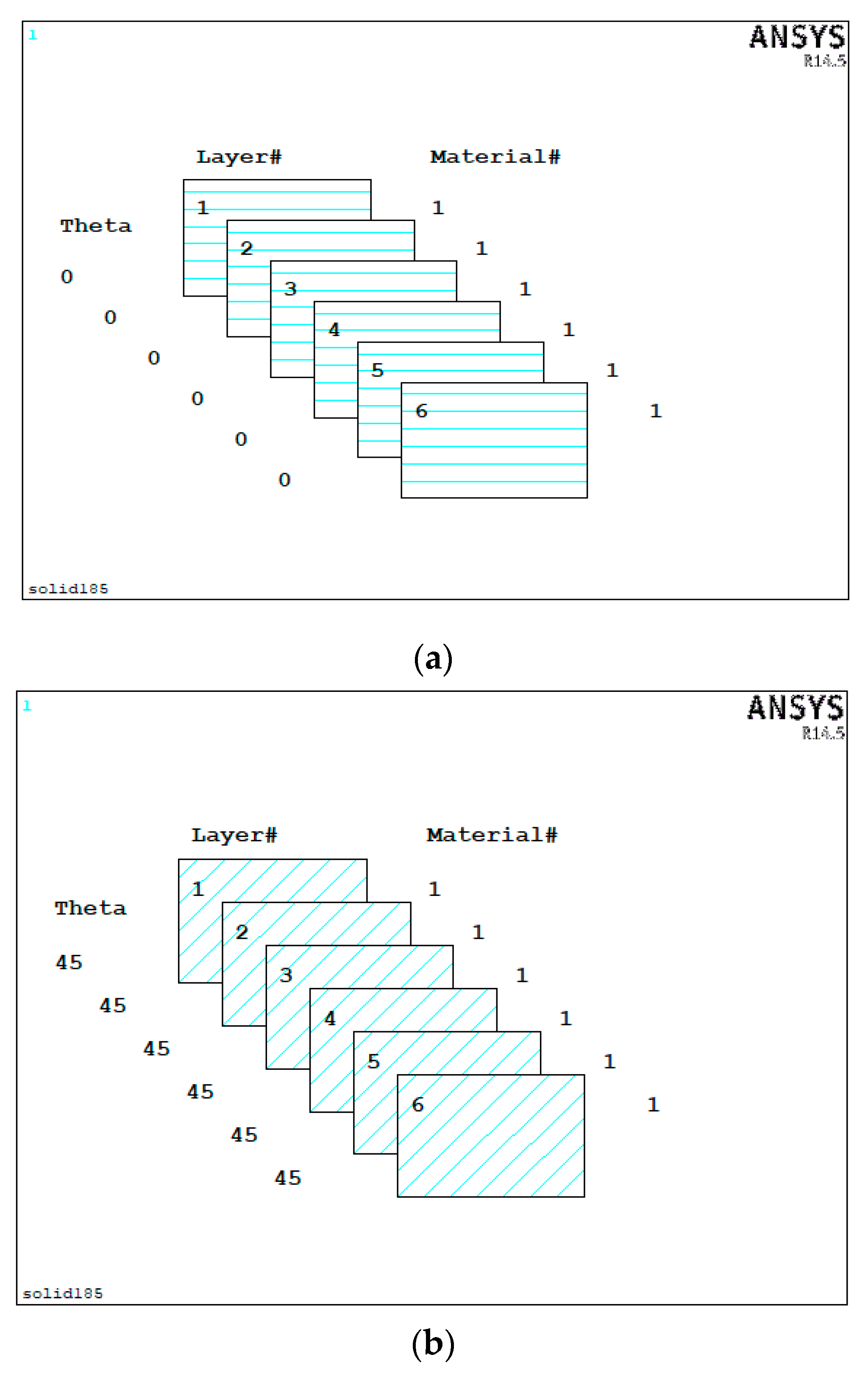
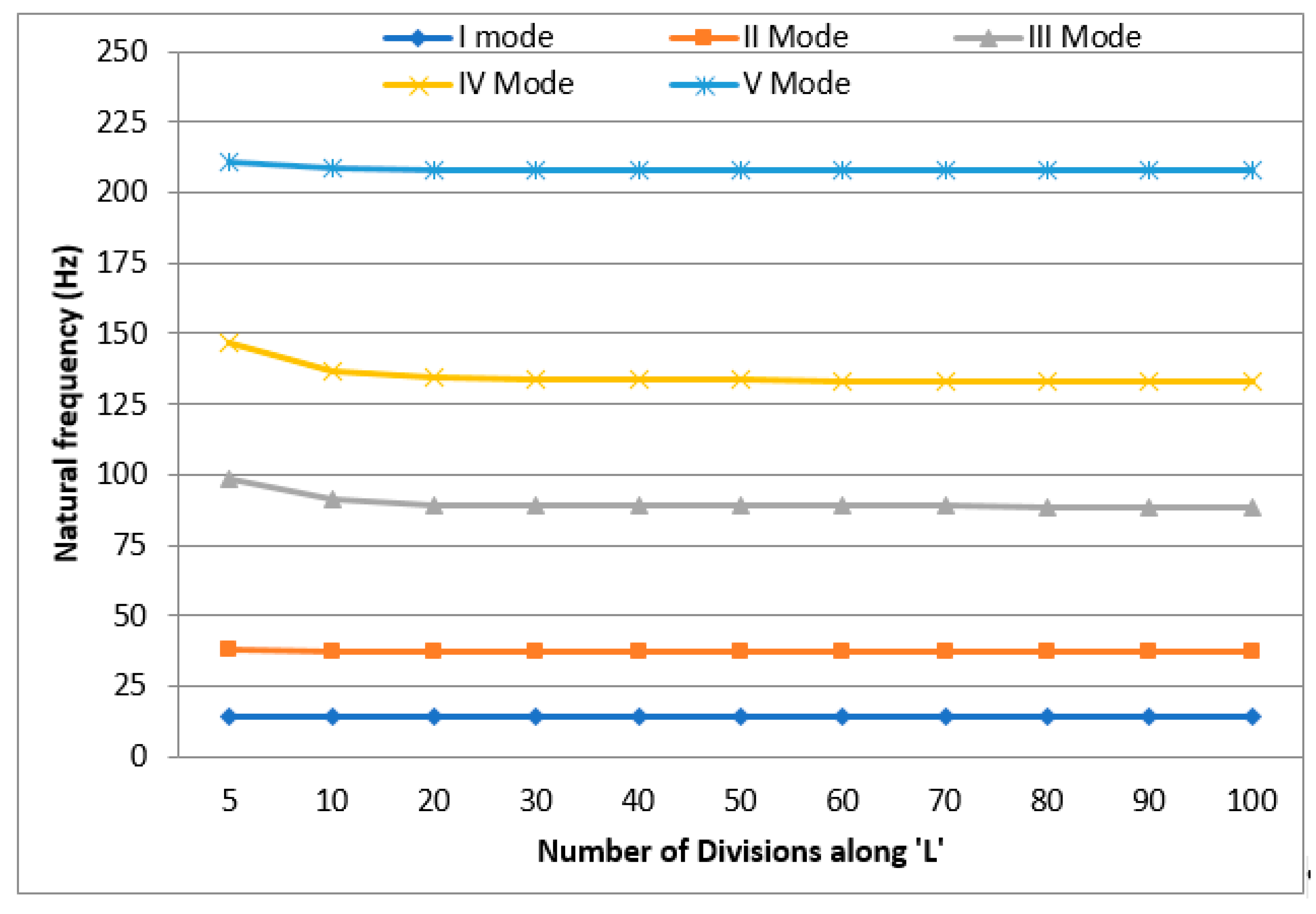
2.2.1. FE Modelling of the Laminated Composite Plate

The numerical modal analysis is carried out using commercial FE code ANSYS to formulate the finite element model of intact and cracked glass fiber reinforced laminated composite plates for investigating its free vibration behaviour. A laminated composite plate consisting of six plies [ 0 ] S and [ 45 ] S is considered. The glass fiber is used as the reinforcement and epoxy resin as the matrix with a unidirectional layup for the composite plates. The material properties calculated using rule of mixtures (Appendix A) and used for the FE analysis are listed in Table 2 and Table 3. The composite plate has a length L = 500 mm, width W = 250 mm and depth h = 5 mm with each ply of thickness 0.833 mm, thus adding up to 6 layers. The FEA is carried out by employing a 3-D layered structural solid element (SOLID185) which has 8 nodes and 6 degrees of freedom per node. The translations and rotations about the X, Y and Z axes are the six degrees of freedom used in the analysis. The shell section is utilized to define the layer configuration as shown in the Figure 3.
The bottom layer is defined as Layer 1 and the stacking of the other layers is done from bottom to top along the positive Z-axis of the Cartesian coordinate system. The number of elements of the FE models was finalized based on the convergence test (Figure 4) resulting in a mesh size of 12,000 elements (100 along the length, 20 along the width and 6 along the depth). The natural frequencies and mode shapes of the laminated composite plates are determined theoretically by carrying out Eigen value modal analysis. The natural frequencies of the fundamental in-plane bending modes (Mode 1,2 and 3) are extracted using the Block Lanczos method. The result from the FEA i.e., displacements is utilized to determine the curvature mode shapes for damage detection. Validation of the FE model is done through comparison with the experimental results.

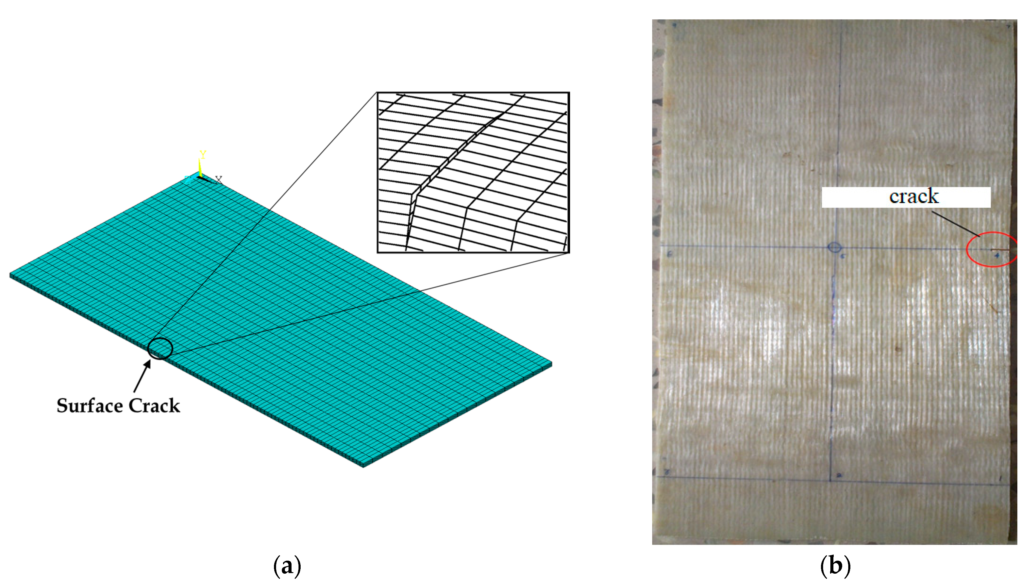
2.2.2. Modelling of the Crack

The crack is modelled in the structure by the technique of releasing of nodes at the location of the damage for the required damage depth ‘a’ and damage length ‘b’ as shown in Figure 1 and Figure 5.
This causes a discontinuity in the FE model of the composite plate structure thus simulating the scenario of damage. This technique allows modelling of damage through partial (in between layers) instead of through-thickness, where the latter has been considered in almost all the previous works. The size of the crack was considered as length (b/W) = 0.1, 0.3, and 0.5 for the depth (a/h) = 0.17, 0.33, 0.5, 0.67, 0.83 and 1 at 0.1 L, 0.2 L, 0.4 L and 0.6 L. The width of the crack is zero since it is considered as air crack. The APDL code developed for the modeling of the crack and FE analysis is given in the Appendix B.

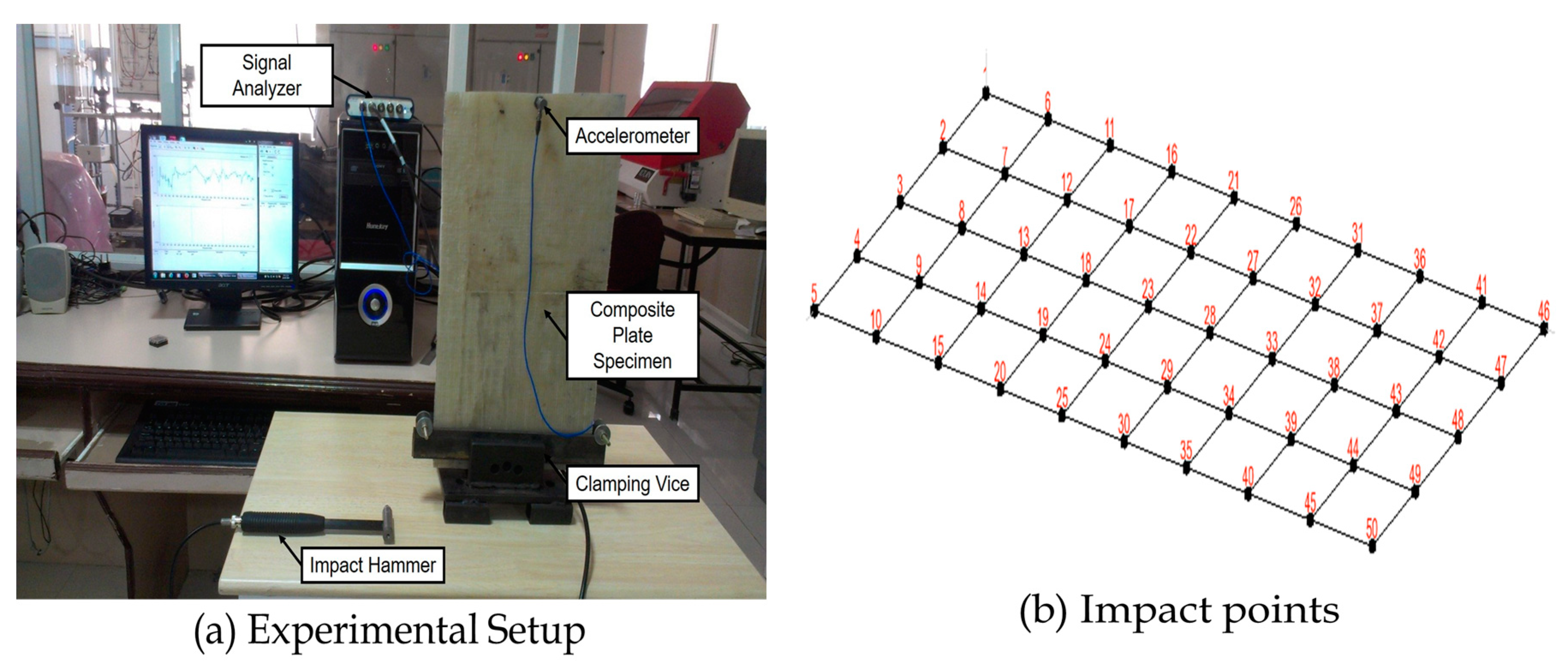
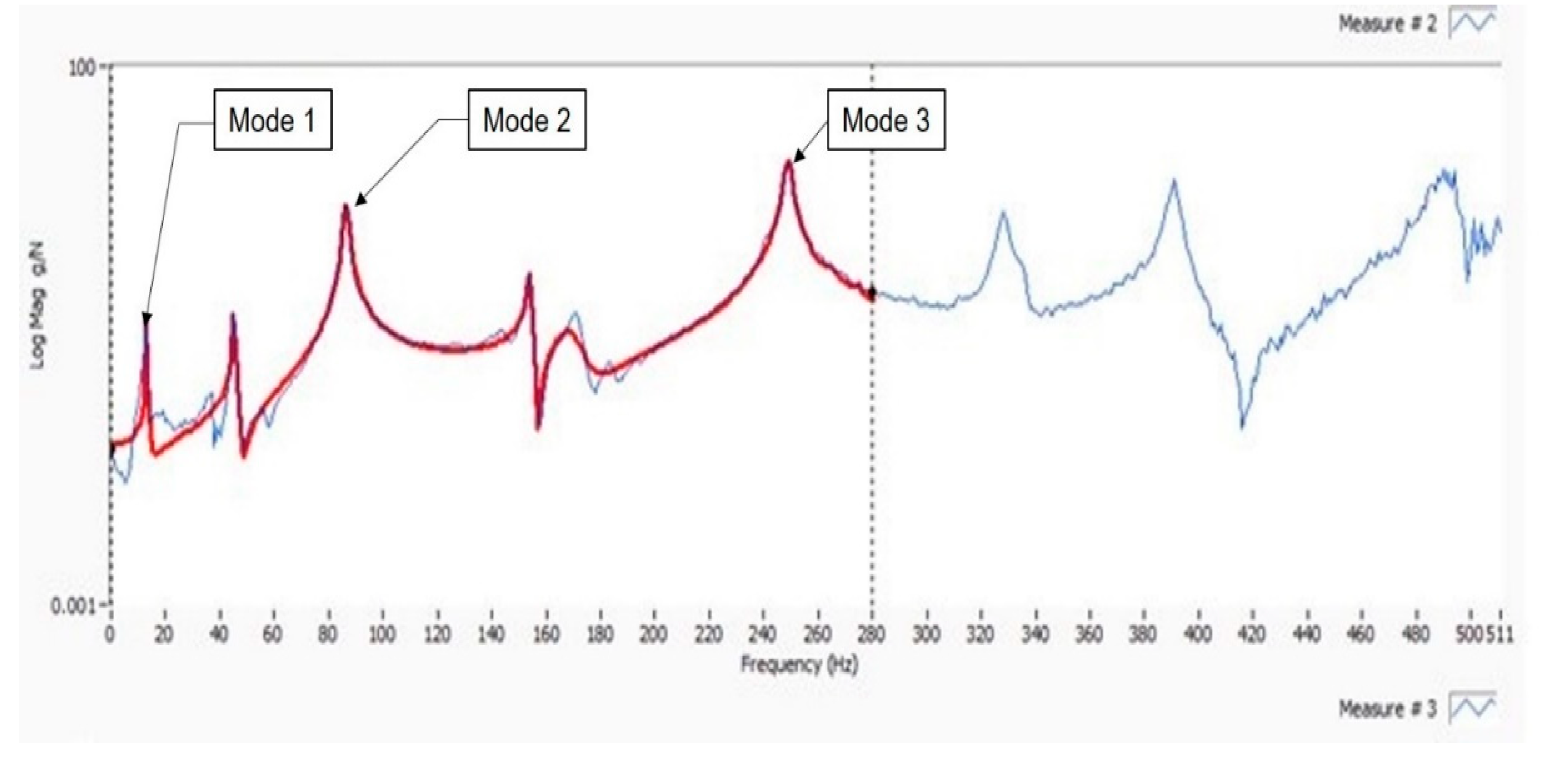
2.3. Experimental Modal Analysis

The composite plate specimens were fabricated using unidirectional E-Glass fiber and Epoxy Resin (LY556) through manual lay-up method via open moulding technique. The pictorial view of the modal analysis setup with the fabricated composite plate specimen mounted on the fixture is shown in Figure 6.
The elastic properties of the composite are evaluated using a simple rule of mixture [50] by knowing the properties of constituents (i.e., fiber and matrix) as obtained from the manufacturer and their corresponding weight fractions in the composite plate. The material and calculated properties of the composite are listed in Table 2 and Table 3 respectively.
The cantilever edge fixity is achieved by clamping one end of the plate on a table using a bench-vice. The plate specimen is divided into 10 × 5 grids along longitudinal and transverse directions with 50 impact points. A PCB Impact hammer is used to excite all the grid points in the composite plate and the corresponding signal acquired from the force transducer is fed into NATIONAL INSTRUMENTS (NI) USB 4311, 4 channel dynamic signal analyser data acquisition system. There lies a difficulty in carrying out modal testing for the current thin-composite plate due to its lightweight and additional masses on the structure significantly affects the output response. Thus, the PCB accelerometer is fixed at the far end of the plate from the fixed end (at grid point 48) for measuring the acceleration outputs. It should be noted that the mass of the plate (1.028 kg) is far higher than that of the sensor (4.5 g).
In the final step of the analysis, LABVIEW-based modal analysis software MODALVIEW is used to extract the modal frequencies and displacement shapes by processing the Frequency Response Functions (FRFs) as shown in Figure 7.
This process involves the curve fitting using least square method by the MODAL VIEW software where each of the peaks of the FRFs indicates a single natural mode of vibration. The modal analysis was carried out in the frequency domain to extract the structural dynamic characteristics especially the natural frequencies and mode shapes which are the required characteristics for the present work. The crack has been induced in the structure using a 1mm thick hacksaw blade cutter at 0.1 L from the fixed end of the plate.

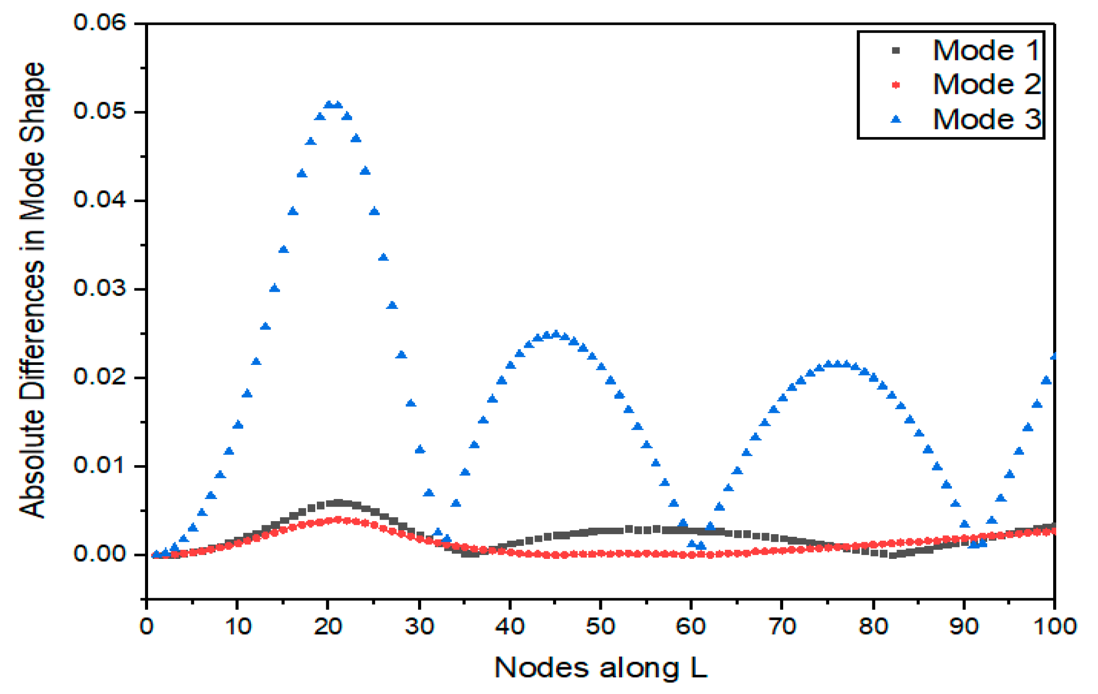
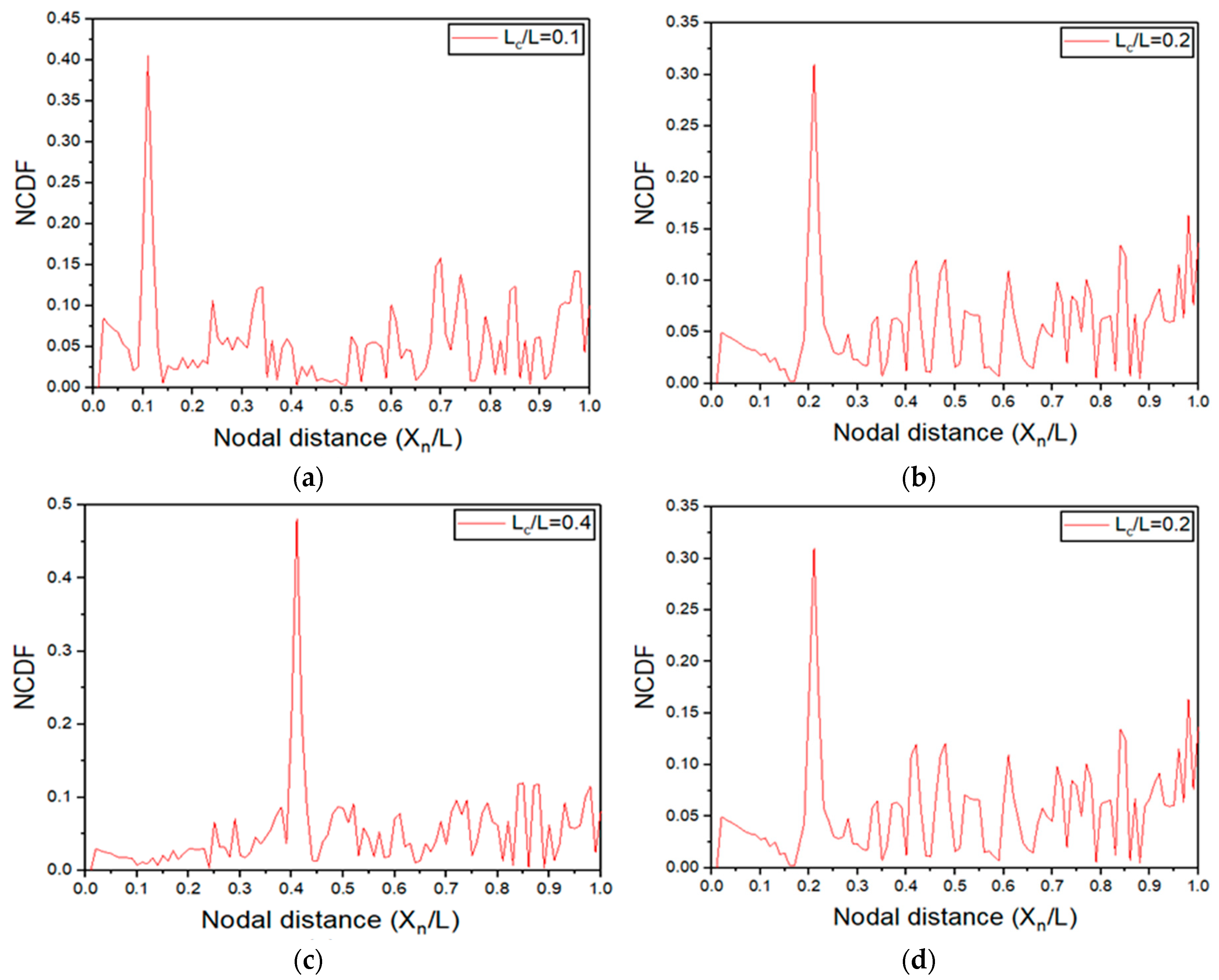
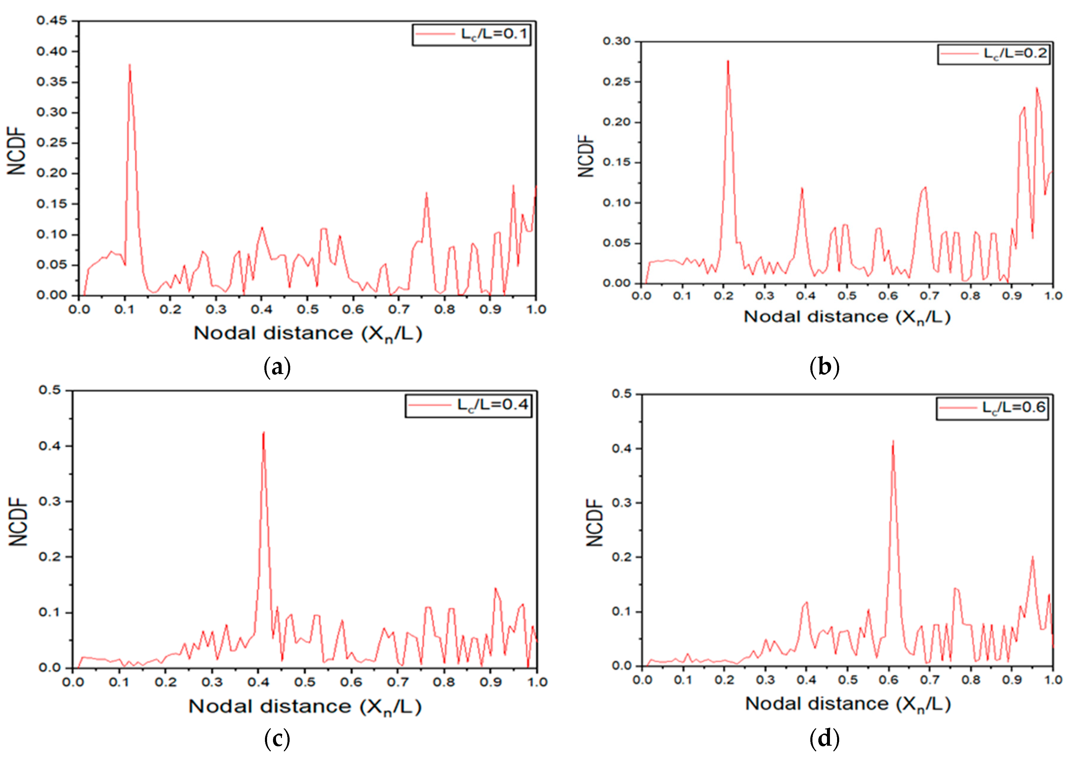
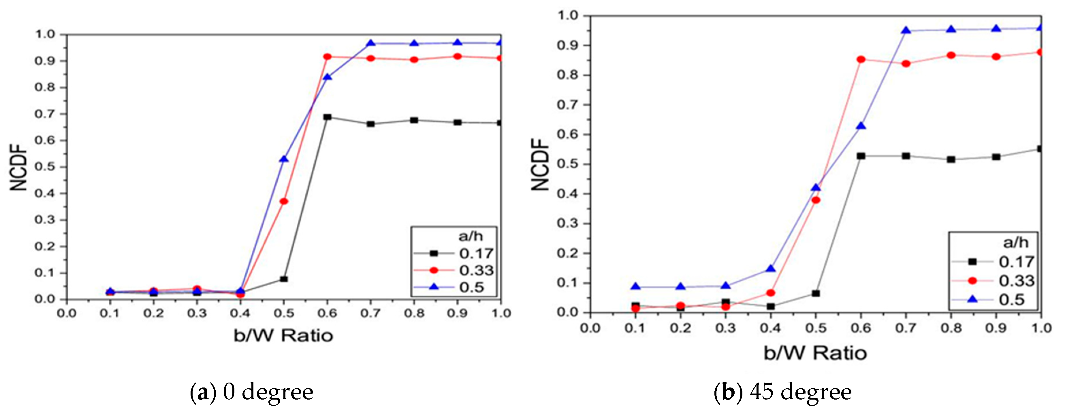
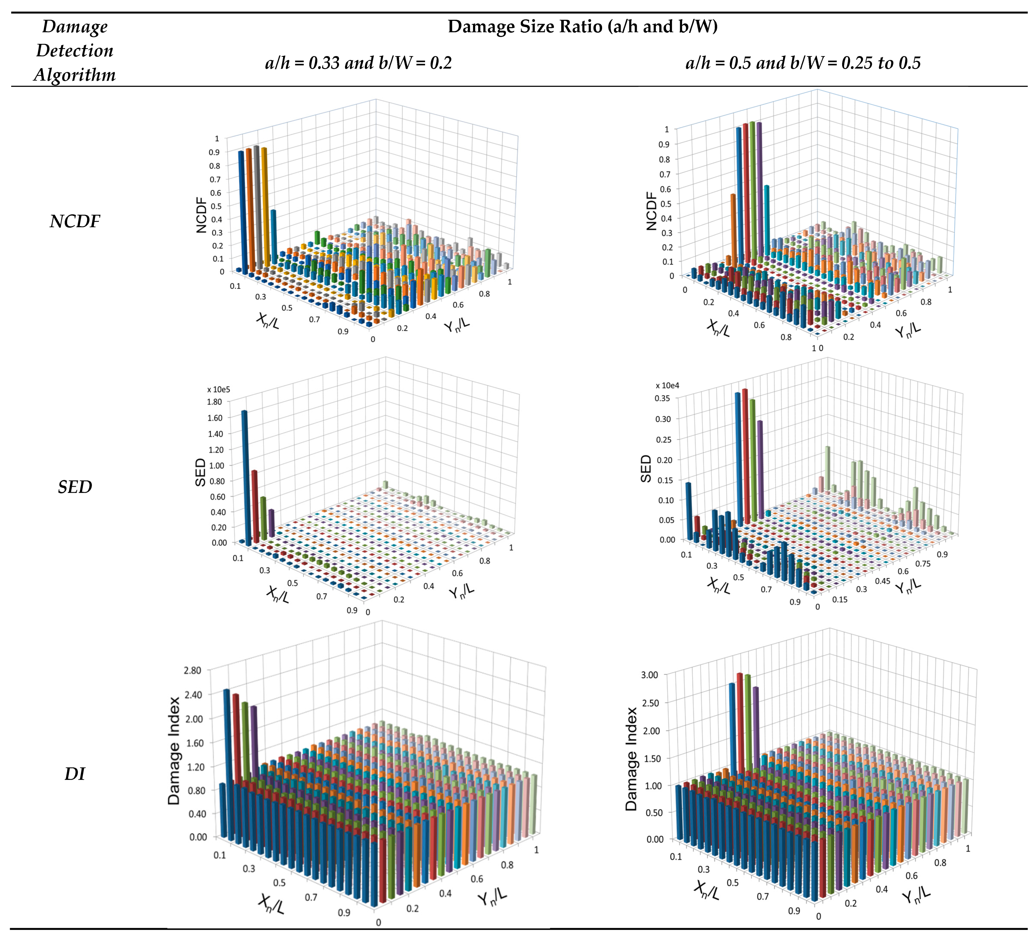
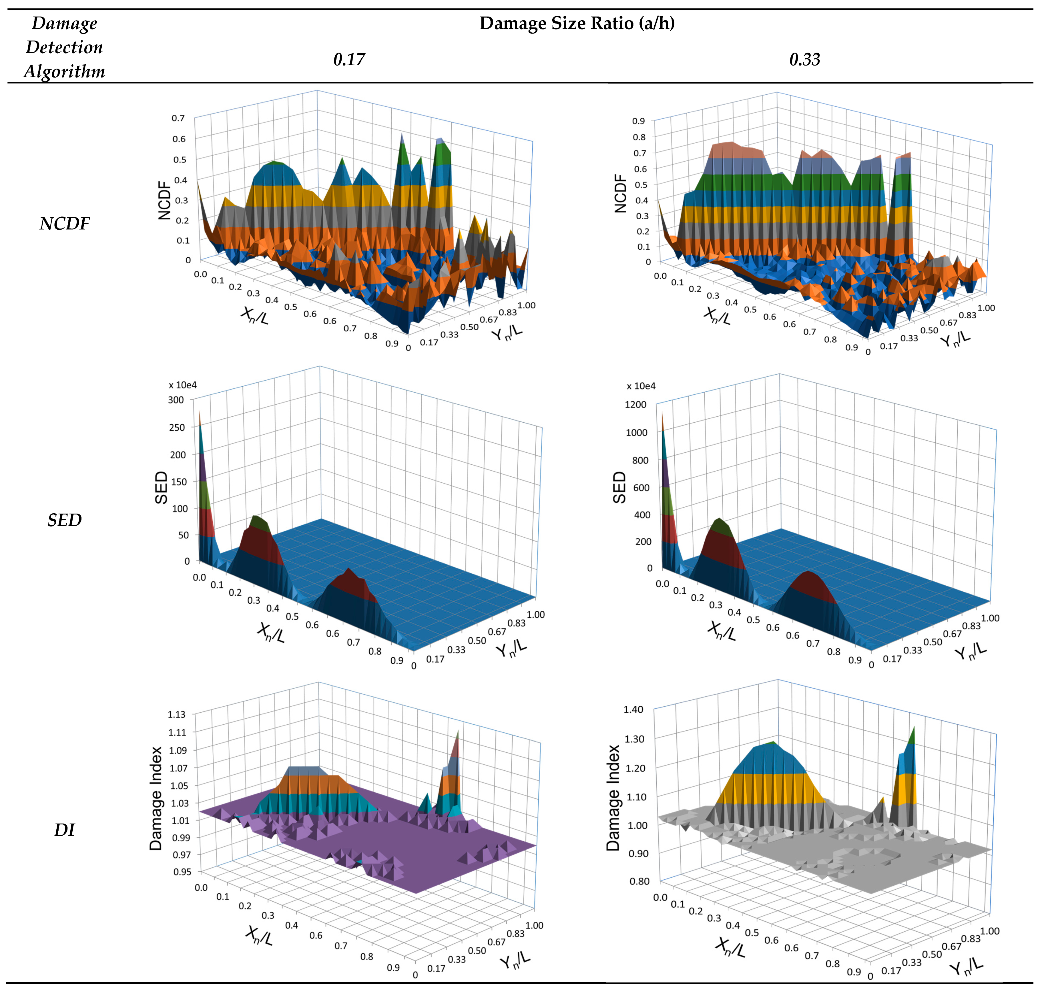
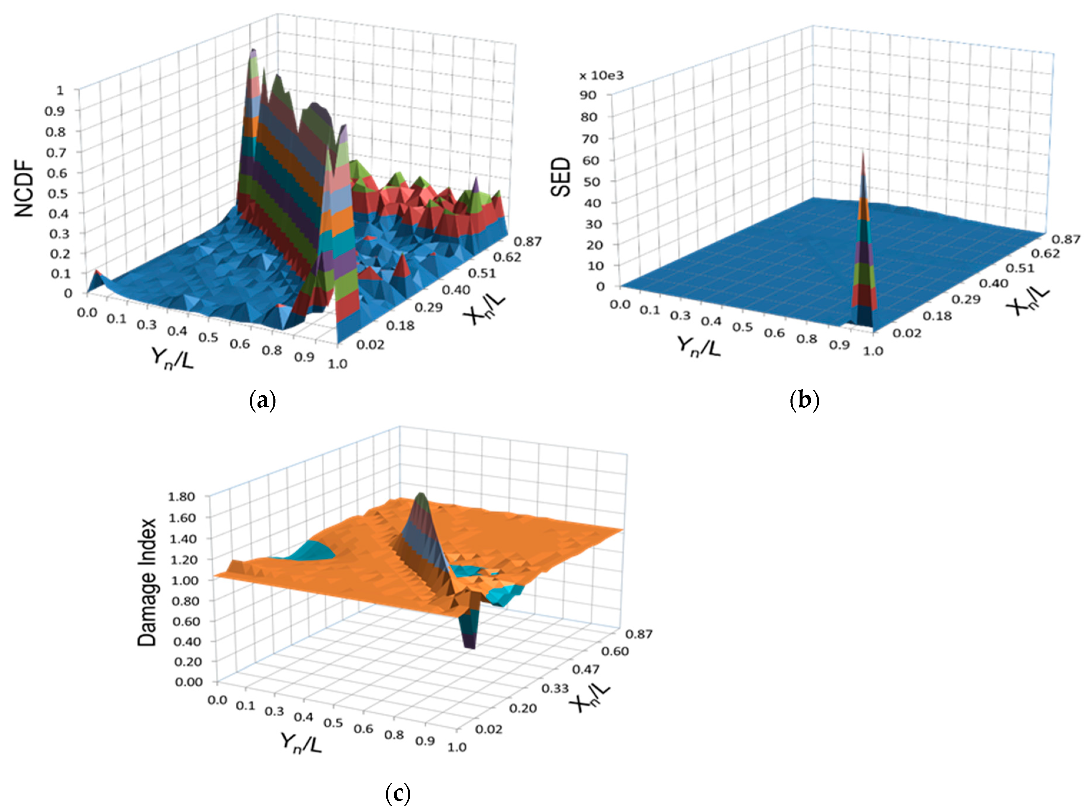
3. Results and Discussion

The natural frequencies and corresponding mode shapes for the first three fundamental bending modes obtained through Finite Element Analysis (FEA) and Experimental Modal Analysis (EMA) are listed in Table 4 and Table 5 respectively for undamaged plates and Table 4 and Table 6 for damaged plates respectively.
The differences in the natural frequencies obtained through both analysis is less than 8% and 1% before and after damage. Also, the displacement shapes obtained through FEA and EMA are comparable with slight changes in the natural frequency since the fabricated plate is not exactly rectangular and error in measurement at certain impact points. It may be observed that for Mode-1, the difference in the values obtained through both analysis is more pronounced. The possible reasons may be attributed to the complexity introduced by non-homogeneity of the structure or defects in the fabricated specimens. Furthermore, the theoretical assumptions that are made in the FE modelling for simplification can cause the numerical models to behave slightly different from the real-life modal analysis tested specimens. The afore-mentioned comparison clearly shows that the FE model is validated and can be used for studying the vibration behaviour of cracked glass fibre reinforced fibre (GFRP) composite rectangular plates.
From the Table 7, it is evident that the percentage change in natural frequencies become more pronounced with the increase of damage depth and length. For example, the least value of percentage change (0.01 or even 0) occurs for the lowest damage depth ratio (a/h = 0.17) and damage length ratio (b/W = 0.1). On the other hand, the maximum change (31.05) occurs in the third mode for the highest a/h = 1.0 (through thickness damage) and b/W = 0.5. These variations in the frequency can be used to determine the presence but not for localization of damage. To realize the sensitivity of the mode-shape change for detection of damage, a test case is considered for crack size a/h = 0.1, b/W = 0.2 located at 0.2 L from the fixed end. The absolute difference in the mode shape is shown in Figure 8.
From the graph, it is observed that the detection of damage using the change of mode shapes is very difficult as evidenced in the existing studies. Hence, the sensitivity of the second order derivative of the displacement mode shape (Modal Curvature) is examined in the following sections with a motivation from similar approaches in the literature.
Through the observation of natural frequencies and mode shapes obtained for undamaged and damaged structures, the presence of damage cannot be identified truthfully. It is hard to detect small sized crack damages based on the afore-mentioned modal parameters alone. The following section investigates the detection capability of modal curvature and its derivative parameters such as NCDF, DI and SED. The Figure 9 and Figure 10 show the mapping of NCDF for various crack locations along the longitudinal edge of the plate i.e., 0.1 L, 0.2 L, 0.4 L, 0.6 L and for damage size, a/h = 0.33 and b/W = 0.5 for [ 0 ] S and [ 45 ] S .
A distinctive peak is observed in all four plots, revealing the location of the crack. It can be noted that the normalization of the curvature damage factor has minimized the misleading peaks in regions away from the damage location. Irrespective of the location of the crack in the structure, NCDF clearly indicates the presence and location of the damage.
In all the above cases of damage detection, the NCDF value is computed at the central axis of the composite plate structure even though the damage is located far away from the central axis. This is considered for the sake of requirement of minimum number of sensors for mode shape measurement through experimental methods. The NCDF is unable to detect the damage in plate structures if b/W < 0.5 for any value of damage depth ratio as shown in Figure 11.
Therefore, due to the limitation of the NCDF computed at central axis in detection of damage located at a distance from the central axis in plate-like structures, the damage indicator is computed at selected points on top surface of the plate. The following section examines the damage detection through NCDF and the damage detection algorithms based on modal strain energy i.e., SED and DI.
  • Case 1: [ 0 ] S Layup
The NCDF, SED and DI for damage located at 0.1 L with a/h = 0.33, 0.5 and b/W = 0.2, 0.25 to 0.5 (crack located at a distance from the longitudinal edge) in the cantilever composite plate [ 0 ] S are shown in Figure 12.
From these plots, the location of damage is clearly detected through the appearance of characteristic peak at damage location. The results obtained are encouraging as it can be clearly seen that all the three algorithms perform fairly by indicating the presence of the damage as peaks, though SED shows a few extra peaks at other locations as well.
  • Case 2: [ 45 ] S Layup
Figure 13 shows the plots for the three damage detection algorithms for a crack inclined at 45° to the longitudinal axis of [ 45 ] S for two sizes of damage, a/h = 0.17, 0.33 and b/W = 1 (through the width of the plate).
It can be inferred that NCDF clearly shows the peak and DI to some extent throughout the length of the crack across the width of the plate. Nevertheless, SED does not indicate the presence of crack as a few peaks are observed in both damage depth ratio cases and the damage is barely discernible. In NCDF, although the peak occurred at region surrounding the location of the surface crack, it can be observed that a few peaks emerged in locations away from the damage. It can also be noticed that the magnitude of the peak increases as the size of the damage increases which can be attributed to the corresponding loss in stiffness.
Since a plate structure is characterized by a two-dimensional curvature, it is interesting to investigate the effectiveness of the three damage detection algorithms mapped using the displacement response obtained at the lateral axis (Y-direction). It can be clearly seen from Figure 14 that NCDF shows the presence of damage throughout the width of the plate followed by Damage Index which shows the presence of damage up to some extent. The SED shows a bare minimum of a few peaks thus it cannot be applied as a potentially viable damage detection algorithm in comparison with the other two for slant cracks.

4. Conclusions

The main objectives of this investigation are to ascertain the effectiveness of existing damage detection algorithms for laminated composite plate structures and observe their relative merits. Three damage detection algorithms are investigated to detect transverse and angular cracks. The damaged plate is successfully modelled using the novel method called as node releasing technique in a modal analysis by employing Finite element analysis. The reliability of the model is ensured by carrying out the convergence test and an experimental modal analysis which shows positive agreement to the numerical results. This study considers only the fundamental bending modes of the plate structure before and after the damage. The changes in natural frequency for various crack sizes are analysed and it could be concluded that the percentage change in the values increase with increasing size of the damage. The ineffectiveness of absolute mode shape difference as a tool for identifying the presence of damage led to the investigation of the damage indicators based on Curvature Mode shape (CMS) and modal strain energy.
The study based on NCDF shows that it is incapable of detecting damages for b/W < 0.5 for all damage depth ratios. This limitation is attributed to the fact that the computation of the damage indicator is carried out using the data recorded at the central axis of the plate and the location of the damage is far away from it. Thus, the algorithm is calculated at selected points at the top surface of the plate to examine the sensitivity of the three damage detection algorithms. The plots of NCDF, SED and DI clearly indicate the presence of the damage for transverse cracks in [ 0 ] S and [ 45 ] S in the form of distinguishing peaks at the damage location. In the case of damages located at a distance from the edge of the plate and in-between the layers, all the three algorithms display distinctive peaks. For the slant crack, NCDF detected the presence of damage better than the other two damage indices due to its incapability.
Further investigation can consider sensitivity analysis of the afore-mentioned damage indicators for multiple damages of various sizes in complex engineering applications such as non-circular cylindrical, conical and double curvature spherical shell structures. Also, exploration can be extended for upcoming complex fiber configurations such as 3-d pinned woven fabric and other types of damages in composites such as sub-surface defects.
The following are the future works may be implemented for damage detection in laminated composite structures based on the present work:
  • In the present work, the damage detection is examined using the theoretical modal analysis of the composite plate structures with the help of the damage detection algorithms. The informative data of the damaged structures predicted by the theoretical method of damage detection can be useful for the purpose of implementing online structural health monitoring/condition monitoring via the emerging technologies like augmented reality, digital twin of products/structures in real life applications with the support of Internet of Things (IOT), neural networks and artificial intelligence like concepts.
  • The findings of the theoretical damage detection procedure may be used as pre-requisites in the field of engineering fracture mechanics to predict the remaining life of the damaged structures in order to avoid sudden failure of the structures.
  • Even though, the damage detection methods used in the present work are concentrated on the detection of damage which exists from top surface to partial thickness of a laminated composite structure, these methods may be extended to examine the effectiveness of damage detection methods based on curvature mode shape in detecting the sub-surface damage of a laminated composite structure.

Author Contributions

Conceptualization, C.K. and M.G.; methodology, M.G.; software, M.G.; validation, C.K., M.G. and G.K.; formal analysis, G.K.M.; investigation, M.G.; resources, C.K.; data curation, M.G.; writing—original draft preparation, C.K.; writing—review and editing, M.G.; visualization, G.K.M.; supervision, C.K.; project administration, M.G. All authors have read and agreed to the published version of the manuscript.

Funding

This research received no external funding.

Acknowledgments

The authors sincerely thank RMK Engineering College, Kavaraipettai, Tamil Nadu, India, for providing the testing facilities.

Conflicts of Interest

The authors declare no conflict of interest.

Appendix A

Micromechanical Analysis of Laminated Composite Plate:
Weight of the Unidirectional fiber = 950 g/m2 (GSM)
Area of fiber = 0.565*0.3 m2
Area of six layers of fiber = 0.565*0.3*6 m2 = 1.0509 m2345
Mass   of   fiber   of   the   fabricated   laminate ,   m f   =   1.0509   m 2 * 0.95   kg / m 2
m f   =   0.965   kg
Fiber   weight   fraction ,   W f   =   w f   w c =   0.965 1.883
Wf = 0.51248
Density of the laminated composite is given by
1 ρ c   =   W f ρ f   + 1 W f ρ m
1 ρ c =   0.51248 2.54 +   1 0.51248 1.2
ρ c = 1645   kg / m 3
Fiber   volume   fraction ,   v f   =   ϑ f ϑ c   =   0.3318
vf = 0.3318
Evaluation of Elastic Moduli
E 1   =   E f v f   +   E m   ( 1 v f )
E 1   =   ( 72 * 0.3318 )   +   ( 2.1 * ( 1     0.3318 ) )
E 1   =   25.295   Gpa
From the stress—strain graph obtained from UTM test,
E11 = 24.64 Gpa
E 2 =   E m   [ E f + E m + ( E f E m ) v f E f + E m ( E f E m ) v f ]
E 2   =   2.1   [ 72 + 2.1 + ( 72 2.1 ) 0.3318 72 + 2.1 ( 72 2.1 ) 0.3318 ]
E 2   =   E 3     =   4.0137   Gpa
Evaluation of Poisson’s Ratio
υ 12   =   υ f v f +   υ m ( 1   v f )   ( 3.15 )
υ 12 =   0.25 * 0.3318   +   0.3 ( 1     0.3318 )
υ 12   =   υ 13     =   0.2834
υ 23   =   υ f v f   +   υ m ( 1     v f )   [ 1 + υ m υ 12 E m / E 11 1 υ m 2 + υ m υ 12 E m / E 11 ]
υ 23   =   0.25 * 0.3318   +   0.34 ( 1     0.3318 )   [ 1 + 0.3 0.2834 * ( 2.1 / 25.295 ) 1 0.3 2 + 0.2834 *   2.1 *   ( 2.1 / 25.295 ) ]
υ 23   =   0.3496
Evaluation of Rigidity Moduli
G 12 =   G m   [ G f + G m + ( G f G m ) v f G f + G m ( G f G m ) v f ]
G 12   =   0.807   [ 30 + 0.807 + ( 30 0.807 ) * 0.3318 30 + 0.807 ( 30 0.807 ) * 0.3318 ]
G 12   =   G 13 =   1.547   Gpa
G 23   =   E 22 2 ( 1 + υ 23 )
G 23   =   4.0137 2 ( 1 + 0.3497 )
G 23   =   1.487   Gpa

Appendix B. A Sample ANSYS APDL Code Developed for Modal Analysis of the Cantilevered Composite Plate Structure with Damage

/CLEAR
/PREP7
/title,solid185
ET,1,solid185
KEYOPT,1,3,1
!KEYOPT,1,2,2
KEYOPT,1,8,1
SECTYPE,1,SHELL
SECDATA,.000833,1,0,9
MP,EX,1,39.805E9
,EY,1,9.98E9
,EZ,1,9.98E9
,PRXY,1,0.263
,PRYZ,1,0.318
,PRXZ,1,0.263
,GXY,1,3.98E9
,GYZ,1,3.78E9
,GXZ,1,3.98E9
,DENS,1,2082.18
N,1
,11,0.045
FILL
NGEN,21,11,1,11,1,,,0.012
ngen,7,231,1,231,1,,0.000833
e,12,13,2,1,243,244,233,232
EGEN,10,1,-1
EGEN,20,11,1,10,1
egen,6,231,1,200,1
N,1618,0.045
,1708,0.45
FILL
NGEN,21,91,1618,1708,1,,,0.012
ngen,7,1911,1618,3528,1,,0.000833
e,1709,1710,1619,1618,3620,3621,3530,3529
EGEN,90,1,-1
EGEN,20,91,1201,1290,1
egen,6,1911,1201,3000,1
NSEL,S,LOC,X,0.045
NSEL,R,LOC,Z,0,0.12
NSEL,A,LOC,Y,0,0.002499
NUMMRG,NODES
ALLSEL
!LSEL, S, LINE, ,1
!LSEL, A, LINE, ,3
!LSEL, A, LINE, ,6
!LSEL, A, LINE, ,8
!CM,TH,LINE
!CMSEL,,TH
!LESIZE,TH, , ,1, , , , ,1
!D,1,ALL,,,664,51
nsel,s,loc,x,0
d,all,all
allsel
FINISH
/SOLU
ANTYPE,MODAL
MODOPT,LANB,6
SOLVE
FINISH
/POST1
SET,LIST
SET,FIRST
PLDISP,1
nsel,s,loc,z,0.12
nsel,r,loc,y,0.002499
PRNSOL,U,Y
SET,NEXT
SET,NEXT
PLDISP,1
PRNSOL,U,Y
SET,LAST
PLDISP,1
PRNSOL,U,Y

References

  1. Moreno-garcía, P.; Araújo, J.V.; Lopes, H. A new technique to optimize the use of mode shape derivatives to localize damage in laminated composite plates. Compos. Struct. 2014, 108, 548–554. [Google Scholar] [CrossRef]
  2. Fan, W.; Qiao, P. A 2-D continuous wavelet transform of mode shape data for damage detection of plate structures. Int. J. Solids Struct. 2009, 46, 4379–4395. [Google Scholar] [CrossRef] [Green Version]
  3. Schilling, P.J.; Karedla, B.P.R.; Tatiparthi, A.K.; Verges, M.A.; Herrington, P.D. X-ray computed microtomography of internal damage in fiber reinforced polymer matrix composites. Compos. Sci. Technol. 2005, 65, 2071–2078. [Google Scholar] [CrossRef]
  4. Naito, K.; Kagawa, Y.; Kurihara, K. Dielectric properties and noncontact damage detection of plain-woven fabric glass fiber reinforced epoxy matrix composites using millimeter wavelength microwave. Compos. Struct. 2012, 94, 695–701. [Google Scholar] [CrossRef]
  5. Bourchak, M.; Farrow, I.R.; Bond, I.P.; Rowland, C.W.; Menan, F. Acoustic emission energy as a fatigue damage parameter for CFRP composites. Int. J. Fatigue. 2007, 29, 457–470. [Google Scholar] [CrossRef]
  6. Mian, A.; Han, X.; Islam, S.; Newaz, G. Fatigue damage detection in graphite/epoxy composites using sonic infrared imaging technique. Compos. Sci. Technol. 2004, 64, 657–666. [Google Scholar] [CrossRef]
  7. Bastianini, F.; di Tommaso, A.; Pascale, G. Ultrasonic non-destructive assessment of bonding defects in composite structural strengthenings. Compos. Struct. 2001, 53, 463–467. [Google Scholar] [CrossRef]
  8. Liang, T.; Ren, W.; Tian, G.Y.; Elradi, M.; Gao, Y. Low energy impact damage detection in CFRP using eddy current pulsed thermography. Compos. Struct. 2016, 143, 352–361. [Google Scholar] [CrossRef] [Green Version]
  9. Aymerich, F.; Meili, S. Ultrasonic evaluation of matrix damage in impacted composite laminates. Compos. Part B 2000, 31, 1–6. [Google Scholar] [CrossRef]
  10. Chandrashekhar, M.; Ganguli, R. Damage assessment of structures with uncertainty by using mode-shape curvatures and fuzzy logic. J. Sound Vib. 2009, 326, 939–957. [Google Scholar] [CrossRef]
  11. Dimarogonas, A.D. Vibration of cracked structures: A state of the art review. Eng. Fract. Mech. 1996, 55, 831–857. [Google Scholar] [CrossRef]
  12. Doebling, S.W.; Farrar, C.R.; Prime, M.B.; Shock, T.; Digest, V. Summary Review of Vibration-Based Damage Identification Methods. Shock Vib. Dig. J. 1998, 30, 91–105. [Google Scholar] [CrossRef] [Green Version]
  13. Fan, W.; Qiao, P. Vibration-based Damage Identification Methods: A Review and Comparitative study. Struct. Heal. Monit. 2011, 10, 83–111. [Google Scholar] [CrossRef]
  14. Chinchalkar, S. Determination of Crack Location in Beams Using Natural Frequencies. J. Sound Vib. 2001, 247, 417–429. [Google Scholar] [CrossRef]
  15. Maia, N.M.; Silva, J.M.; Almas, E.A. Damage Detection in Structures: From Mode Shape to Frequency Response Function Methods. Mech. Syst. Signal Process. 2003, 17, 489–498. [Google Scholar] [CrossRef]
  16. Abdo, M.A.B.; Hori, M. A Numerical Study of Structural Damage Detection Using Changes in the Rotation of Mode Shapes. J. Sound Vib. 2002, 251, 227–239. [Google Scholar] [CrossRef]
  17. Pandey, A.; Biswas, M.; Samman, M. Damage Detection From Mode Changes in Curvature Mode Shapes. J. Sound Vib. 1991, 145, 321–332. [Google Scholar] [CrossRef]
  18. Qiao, P.; Lu, K.; Lestari, W.; Wang, J. Curvature mode shape-based damage detection in composite laminated plates. Compos. Struct. 2007, 80, 409–428. [Google Scholar] [CrossRef]
  19. Wahab, M.A.; Roeck, G.D.E. Damage detection in bridges using modal curvatures: Application to a real damage scenario. J. Sound Vib. 1999, 226, 217–235. [Google Scholar] [CrossRef]
  20. Lu, X.B.; Liu, J.K.; Lu, Z.R. A two-step approach for crack identification in beam. J. Sound Vib. 2013, 332, 282–293. [Google Scholar] [CrossRef]
  21. Cornwell, P.; Doebling, S.; Farrar, C. Application of the Strain Energy damage detection method to plate-like structures. J. Sound Vib. 1999, 224, 359–374. [Google Scholar] [CrossRef]
  22. Hu, H.; Wang, B.; Lee, C.; Su, J. Damage detection of surface cracks in composite laminates using modal analysis and strain energy method. Compos. Struct. 2006, 74, 399–405. [Google Scholar] [CrossRef]
  23. Wang, Z.X.; Qiao, P.; Xu, J. Vibration analysis of laminated composite plates with damage using the perturbation method. Compos. Part B Eng. 2015, 72, 160–174. [Google Scholar] [CrossRef]
  24. Narkis, Y. Identification of crack location in vibrating simply supported beam. J. Sound Vib. 1992, 174, 549–558. [Google Scholar] [CrossRef]
  25. Krawczuk, M.; Ostachowicz, W.M. Modelling and vibration analysis of a cantilever composite beam with a transverse open crack. J. Sound Vib. 1995, 183, 58–78. [Google Scholar] [CrossRef]
  26. Ruotolo, R.; Surace, C.; Crespu, P.; Storer, D. Harmonic analysis of the vibrations of a cantilevered beam with a closing crack. Compuars Swucrures 1996, 61, 1057–1074. [Google Scholar] [CrossRef]
  27. Tsai, T.C.; Wang, Y.Z. Vibration analysis and diagnosis of a cracked shaft. J. Sound Vib. 1996, 192, 607–620. [Google Scholar] [CrossRef]
  28. Ratcliffe, C.P. Damage detection using a modified laplacian operator on mode shape data. J. Sound Vib. 1997, 204, 505–517. [Google Scholar] [CrossRef]
  29. Fernadndez-saez, J.; Rubio, L.; Navarro, C. Approximate calculation of the fundamental frequency for bending vibrations of cracked beams. J. Sound Vib. 1999, 225, 345–352. [Google Scholar] [CrossRef]
  30. Yang, X.F.; Swamidas, A.S.J.; Seshadri, R. Crack identification in vibrating beams using the energy method. J. Sound Vib. 2001, 244, 339–357. [Google Scholar] [CrossRef]
  31. Roy Mahapatra, D.; Gopalakrishnan, S. A spectral finite element model for analysis of axial–flexural–shear coupled wave propagation in laminated composite beams. Compos. Struct. 2003, 59, 67–88. [Google Scholar] [CrossRef]
  32. Xia, Y.; Hao, H. Statistical damage identification of structures with frequency changes. J. Sound Vib. 2003, 263, 853–870. [Google Scholar] [CrossRef]
  33. Cam, E.; Orhan, S.; Luy, M. An analysis of cracked beam structure using impact echo method. NDT E Int. 2005, 38, 368–373. [Google Scholar] [CrossRef]
  34. Loya, J.A.; Rubio, L.; Fernandez-Saez, J. Natural frequencies for bending vibrations of Timoshenko cracked beams. J. Sound Vib. 2006, 290, 640–653. [Google Scholar] [CrossRef] [Green Version]
  35. Orhan, S. Analysis of free and forced vibration of a cracked cantilever beam. NDT E Int. 2007, 40, 443–450. [Google Scholar] [CrossRef]
  36. Yu, L.; Cheng, L.; Yam, S.M.; Yan, Y.J.; Jiang, J.S. Online damage detection for laminated composite shells partially filled with fluid. Compos. Struct. 2007, 80, 334–342. [Google Scholar] [CrossRef]
  37. Peng, Z.K.; Lang, Z.Q.; Chu, F.L. Numerical analysis of cracked beams using nonlinear output frequency response functions. Comput. Struct. 2008, 86, 1809–1818. [Google Scholar] [CrossRef]
  38. Dessi, D.; Camerlengo, G. Damage identification techniques via modal curvature analysis: Overview and comparison. Mech. Syst. Signal Process. 2015, 52, 181–205. [Google Scholar] [CrossRef]
  39. Laflamme, S.; Cao, L.; Chatzi, E.; Ubertini, F. Damage Detection and Localization from Dense Network of Strain Sensors. Shock Vib. 2016, 2016, 2562949. [Google Scholar] [CrossRef] [Green Version]
  40. Yang, Z.-B.; Radzienski, M.; Kudela, P.; Ostachowicz, W. Two-dimensional Chebyshev pseudo spectral modal curvature and its application in damage detection for composite plates. Compos. Struct. 2017, 168, 372–383. [Google Scholar] [CrossRef]
  41. Ashory, M.; Ghasemi-Ghalebahman, A.; Kokabi, M. An efficient modal strain energy-based damage detection for laminated composite plates. Adv. Compos. Mater. 2018, 27, 147–162. [Google Scholar] [CrossRef]
  42. Pan, J.; Zhang, Z.; Wu, J.; RamRamakrishnan, K.; Singh, H.K. A novel method of vibration modes selection for improving accuracy of frequency-based damage detection. Compos. Part B Eng. 2019, 159, 437–446. [Google Scholar] [CrossRef]
  43. Bao, Y.; Valipour, M.; Meng, W.; Khayat, K.H.; Chen, G. Distributed fiber optic sensor-enhanced detection and prediction of shrinkage-induced delamination of ultra-high-performance concrete overlay. Smart Mater. Struct. 2017, 26, 085009. [Google Scholar] [CrossRef]
  44. Kannivel, S.k.; Subramanian, H.; Arumugam, V.; Dhakal, H.N. Low-Velocity Impact Induced Damage Evaluation and Its Influence on the Residual Flexural Behavior of Glass/Epoxy Laminates Hybridized with Glass Fillers. J. Compos. Sci. 2020, 4, 99. [Google Scholar] [CrossRef]
  45. Linke, M.; Flügge, F.; Jose, A. Olivares–Ferrer, Design and Validation of a Modified Compression-After-Impact Testing Device for Thin-Walled Composite Plates. J. Compos. Sci. 2020, 4, 126. [Google Scholar] [CrossRef]
  46. Arena, M.; Viscardi, M. Strain State Detection in Composite Structures: Review and New Challenges. J. Compos. Sci. 2020, 4, 60. [Google Scholar] [CrossRef]
  47. Meng, W.; Khayat, K.H. Experimental and numerical studies on flexural behaviour of ultra high-performance concrete panels reinforced with embedded glass fiber-reinforced polymer grids. Transp. Res. Rec. 2016, 2592, 38–44. [Google Scholar] [CrossRef]
  48. Stamoulis, K.; Georgantzinos, S.K.; Giannopoulos, G.I. Damage characteristics in laminated composite structures subjected to low-velocity impact. Int. J. Struct. Integr. 2019, 11, 670–685. [Google Scholar] [CrossRef]
  49. Dabetwar, S.; Ekwaro-Osire, S.; Dia, J.P. Damage Classification of Composites Based on Analysis of Lamb Wave Signals Using Machine Learning. ASCE-ASME J. Risk Uncert Engrg. Sys. Part B Mech. Engrg 2020. [Google Scholar] [CrossRef]
  50. Georgantzinos, S.K.; Giannopoulos, G.I.; Markolefas, S.I. Vibration Analysis of Carbon Fiber-Graphene-Reinforced Hybrid Polymer Composites Using Finite Element Techniques. Materials 2020, 13, 4225. [Google Scholar] [CrossRef]
  51. Chen, Z.; Zhou, X.; Wang, X.; Dong, L.; Qian, Y. Deployment of a smart structural health monitoring system for long-span arch bridges: A review and a case study. Sensors 2017, 17, 2151. [Google Scholar] [CrossRef] [PubMed]
Figure 1. Geometrical sketch of the laminated composite plate with crack.
Jcs 04 00185 g001
Figure 2. Schematic illustration of grid point arrangement in the plate.
Jcs 04 00185 g002
Figure 3. Layer stack-up in FE modelling of the Laminated Composite plate (a) 0 Degree Lay-up; (b) 45 Degree Lay-up.
Jcs 04 00185 g003
Figure 4. Convergence of the FE mesh of the plate model.
Jcs 04 00185 g004
Figure 5. (a) FE model of cracked laminated composite plate, (b) Real plate with introduced crack.
Jcs 04 00185 g005
Figure 6. Experimental modal analysis.
Jcs 04 00185 g006
Figure 7. FRF curve of cantilevered composite plate (UDL- [ 0 ] S ) modal testing (curve fitting range—0 to 280 Hz).
Jcs 04 00185 g007
Figure 8. Absolute Difference between Displacement Mode Shapes for Intact and Damaged Composite Plate [ 0 ] S with damage at 0.2 L for a/h = 1.0 and b/W = 0.2.
Jcs 04 00185 g008
Figure 9. Normalized Curvature Damage Factor (NCDF) for cantilever composite plate [ 0 ] S with damage size for a/h = 0.33 and b/W = 0.5 at (a) 0.1 L (b) 0.2 L (c) 0.4 L (d) 0.6 L.
Jcs 04 00185 g009
Figure 10. NCDF for cantilever composite plate [ 45 ] S with damage size for a/h = 0.33 and b/W = 0.5 at (a) 0.l L (b) 0.2 L (c) 0.4 L (d) 0.6 L.
Jcs 04 00185 g010
Figure 11. Variation of the NCDF over depth of layers at L_c/L = 0.1 in cantilever composite plate (a) [ 0 ] S ; (b) [ 45 ] S .
Jcs 04 00185 g011
Figure 12. Cantilever composite Plate [ 0 ] S with damage at 0.l L for a/h = 0.33 and b/W = 0.2, a/h = 0.5 and b/W = 0.25 to 0.5 (a) NCDF (b) SED (c) DI.
Jcs 04 00185 g012
Figure 13. Composite Plate [ 45 ] S with damage at 0.1 L inclined at 45° for a/h = 0.17,0.33 and b/W = 1 (a) NCDF (b) SED (c) DI.
Jcs 04 00185 g013
Figure 14. Cantilever Composite Plate [ 45 ] S with damage at 0.1 L inclined at 45° for a/h = 0.33 and b/W = 1 (a) NCDF (b) SED (c) DI plotted in Y-Direction.
Jcs 04 00185 g014
Table 1. Summary of methods used for modeling of cracks in finite element/analytical approach.
S. No.Reference Cited/YearStructure ConsideredMethod of Damage Detection Method of Crack Modeling in Finite Element/Analytical Approach
01Pandey et al. [17]/1991Isotropic BeamChange in Curvature Mode ShapeApproximate reduction in the elemental Young’s modulus at the damaged location
02Narkis [24]/1992Isotropic BeamChange in Natural FrequenciesFor analytical methods of beam like structures, the beam was separated to two halves and damage was considered to be a massless rotational spring where the stiffness of the spring corresponds to the size of the damage
03Krawczuk and Ostachowicz [25]/1995Laminated Composite BeamChange in Natural Frequencies and Mode ShapesFor analytical methods of beam like structures, the beam was separated to two halves and damage was considered to be a massless rotational spring where the stiffness of the spring corresponds to the size of the damage.
04Ruotolo et al. [26]/1996Isotropic BeamMethods based on Frequencies Response FunctionsCracked element with the approach that the elements situated on one side is considered as external forces applied to the cracked element, while the elements on the other side is regarded as constraints.
05Tsai and Wang [27]/1996Isotropic ShaftChange in Natural Frequencies and Mode ShapesFor analytical methods of beam like structures, the shaft was separated to two halves and damage was considered to be a massless rotational spring where the stiffness of the spring corresponds to the size of the damage.
06Ratcliffe [28]/1997Isotropic BeamChange in Curvature Mode ShapeCracks and other forms of localized damage in a structure can lead to reduction in the flexural stiffness (EI), but change in mass is minimal. For the uniform cross-section localized stiffness damage can be introduced by reducing the thickness for one element of the finite element model without altering the mass matrix.
07ABdel Wahab et al. [19]/1999Isotropic Concrete BeamChange in Curvature Mode ShapeApproximate reduction in the elemental Young’s modulus at the damaged location.
08Fernandez-saez et al. [29]/1999Isotropic BeamChange in Natural FrequenciesFor analytical methods of beam like structures, the beam was separated to two halves and damage was considered to be a massless rotational spring where the stiffness of the spring corresponds to the size of the damage.
09Yang et al. [30]/2001Isotropic BeamChange in Strain EnergyModeled cracked beam as a continuous system with varying moment of inertia over the length of the beam.
10Roy Mahapatra and Gopalakrishnan [31]/2003Laminated Composite BeamDynamic Stiffness MethodModeled cracked beam as a continuous system with varying moment of inertia over the length of the beam.
11Yong and Hong Hao [32]/2003Isotropic Beam and PlateMethods based on Change in Natural FrequenciesApproximate reduction in the elemental Young’s modulus at the damaged location.
12Ertugrul Cam et al. [33]/2005Isotropic BeamChange in Natural FrequenciesModeled the crack as v-shaped groove by considering solid finite element available in ANSYS.
13Loya et al. [34]/2006Isotropic BeamChange in Natural FrequenciesFor analytical methods of beam like structures, the beam was separated to two halves and damage was considered to be a massless rotational spring where the stiffness of the spring corresponds to the size of the damage.
14Sadettin Orhan [35]/2007Isotropic BeamChange in Natural FrequenciesModeled the crack as v-shaped groove by considering solid finite element available in ANSYS.
15Yu et al. [36]/2007Laminated Composite Shell Change in Dynamic ResponseConsidered Piezoelectric patches as sensors and actuators to realize automatic damage detections in this finite element model of laminated composite shells partially filled with fluid.
16Peng et al. [37]/2008Isotropic BeamMethods based on Frequencies Response FunctionsApproximate reduction in second moment of area of the cross-section at the damaged location.
17Lu et al. [20]/2013Isotropic PlateChange in Dynamic ResponseApproximate reduction in the elemental Young’s modulus at the damaged location.
18Daniele Dessi and Gabriele Camerlengo [38]/2015Isotropic BeamNatural Frequencies and Modal strain Energy – Based MethodsDamage was modeled as a localized and uniform reduction of the bending stiffness distribution along the dimensional coordinate of the damage. Thus, the damaged beam of was considered as the union of three beam portions along its length.
19Simon Laflamme et al. [39]/2016Wind Turbine Blade as Cantilevered Composite Taper Plate.Methods Based on Change in StrainDamage is considered as a change in the stiffness at the damaged location of the laminate layer.
20Zhi-BoYang et al. [40]/2017Laminated Composite PlateTwo-Dimensional Chebyshev Pseudo Spectral Modal CurvatureIn the damaged area of analytical model, the local thickness is reduced to 95% of the original thickness of the plate.
21Mohammad-Reza Ashory et al. [41]/2018Laminated Composite PlateModal Strain Energy-Based Damage Detection MethodsAssuming a spring model with six degree-of-freedom between adjacent layers corresponding to the six stiffness components of an orthotropic composite material,
the elastic moduli in the damaged region was formulated by the stiffness reduction vector.
22Jingwen Pan et al. [42]/2019Laminated Composite Curved PlateNatural Frequency – Based MethodsA “constrained mode” model was developed by adding pair of contact elements, TARGE170/CONTAC173, between the mating surfaces of the delaminated area.
28Bao et al. [43]/2017Smart Ultra-High-Performance Concrete (UHPC) overlaysFully-Distributed Fiber Optic Sensor.Developed delamination detection system for smart Ultra-High-Performance Concrete (UHPC) overlays using a fully-distributed fiber optic sensor.
29Saravana Kumar et al. [44]/2020Glass/Epoxy Laminates Hybridized with Glass FillersPost Impact Flexural (FAI) test and Acoustic Emission (AE) monitoringInvestigated the low-velocity impact induced damage behavior and its influence on the residual flexural response of glass/epoxy composites improved with milled glass fillers.
30Markus Linke et al. [45]/2020Thin-Walled Composite PlatesModified Compression-After-Impact Testing DeviceInvestigated Failure mechanisms of impact damage in composite structures based on the Compression After Impact (CAI) test procedure
31Maurizio et al. [46]/2020Composite StructuresStrain measurement Provided a state-of-the-art review on strain detection techniques in composite structures.
32Meng et al. [47]/2016Composite PlateFlexural StrengthStudied the flexural behavior of ultrahigh-performance concrete panels reinforced with embedded glass fiber-reinforced polymer grids.
33Stamoulis et al. [48]/2019Laminated Composites Hashin criterionIn this paper, a finite element model based on explicit dynamics formulations is adopted. Hashin criterion is applied to predict the intralaminar damage initiation and evolution. The numerical analysis is performed using the ABAQUS programme.
34Shweta et al. [49]/2020CFRP CompositesMachine Learning (ML) algorithmsThis work contributes to the improvement of intelligent damage classification algorithms that can be applied to health management strategies of composite materials, operating under complex working conditions.
35Stelios et al. [50]/2020Carbon Fiber-Graphene-Reinforced Hybrid Composite PlatesFinite Element AnalysisIn this study, a computational procedure for the investigation of the vibration behavior of laminated composite structures, including graphene inclusions in the matrix, is developed. The material properties required to carryout the FEA are computed using the rule of mixtures.
Table 2. Properties of fiber and matrix.
PropertyGlass FiberEpoxy Resin
Density ,   ρ (kg/m3)26001200
Elastic   Modulus ,   E (GPa)721.2
Shear   Modulus ,   G (GPa)300.807
Poisson s   ratio ,   υ 0.250.3
Table 3. Properties of unidirectional laminated composite plate.
PropertyValue
Density ,   ρ (kg/m3)1645
Elastic   Modulus ,   E x (GPa)25.30
Elastic   Modulus ,   E y =   E z (GPa)4.01
Shear   Modulus ,   G x y = G x z (GPa)1.55
Shear   Modulus ,   G y z   (GPa)1.49
Poisson s   ratio ,   υ x y = υ x z 0.28
Poisson s   ratio ,   υ y z 0.35
Table 4. Natural frequencies of damaged and undamaged plates.
ModeBefore DamageAfter Damage
EMA (Hz)FEA
(Hz)
Δ (%) EMA (Hz)FEA
(Hz)
Δ (%)
113.1414.197.412.8514.040.08
288.3888.670.3985.3188.590.04
3248.91248.640.11245.05247.410.95
Table 5. Natural frequencies and mode shapes (undamaged).
ModeEMA (Hz)FEA (Hz)
113.14
Jcs 04 00185 i001
14.19
Jcs 04 00185 i002
288.38
Jcs 04 00185 i003
88.67
Jcs 04 00185 i004
3248.91
Jcs 04 00185 i005
248.64
Jcs 04 00185 i006
Table 6. Natural frequencies and mode shapes (damaged).
ModeEMA (Hz)FEA (Hz)
112.85
Jcs 04 00185 i007
14.04
Jcs 04 00185 i008
285.31
Jcs 04 00185 i009
88.59
Jcs 04 00185 i010
3245.05
Jcs 04 00185 i011
247.41
Jcs 04 00185 i012
Table 7. Variation in Natural frequencies in the plate structure for different crack lengths and depths.
a/hb/wChange in Natural Frequencies (%)
Mode 1Mode 2Mode 3Mode 4Mode 5
[ 0 ] S [ 45 ] S [ 0 ] S [ 45 ] S [ 0 ] S [ 45 ] S [ 0 ] S [ 45 ] S [ 0 ] S [ 45 ] S
0.170.10.040.020.040.020.040.020.040.020.040.02
0.30.120.090.120.090.120.090.120.090.120.09
0.50.420.220.420.220.420.220.420.220.420.22
0.330.10.160.100.160.100.160.100.160.100.160.10
0.30.600.440.600.440.600.440.600.440.600.44
0.51.060.751.060.751.060.751.060.751.060.75
0.50.10.370.240.370.240.370.240.370.240.370.24
0.31.530.001.530.001.530.001.530.001.530.00
0.52.800.002.800.002.800.002.800.002.800.00
0.670.10.590.380.590.380.590.380.590.380.590.38
0.33.122.283.122.283.122.283.122.283.122.28
0.56.164.466.164.466.164.466.164.466.164.46
0.830.10.730.490.730.490.730.490.730.490.730.49
0.35.374.005.374.005.374.005.374.005.374.00
0.512.589.3612.589.3612.589.3612.589.3612.589.36
1.00.11.380.871.380.871.380.871.380.871.380.87
0.310.337.7110.337.7110.337.7110.337.7110.337.71
0.523.7318.523.7318.523.7318.523.7318.523.7318.5
Publisher’s Note: MDPI stays neutral with regard to jurisdictional claims in published maps and institutional affiliations.

