Article

Parametric Optimization of Isotropic and Composite Axially Symmetric Shells Subjected to External Pressure and Twisting

Chair of Machine Design and Composite Structures, Cracow University of Technology, Ul. Warszawska 24, 31-155 Krakow, Poland
*
Author to whom correspondence should be addressed.
J. Compos. Sci. 2021, 5(5), 128; https://0-doi-org.brum.beds.ac.uk/10.3390/jcs5050128
Submission received: 17 April 2021 / Revised: 6 May 2021 / Accepted: 7 May 2021 / Published: 12 May 2021
(This article belongs to the Special Issue Feature Papers in Journal of Composites Science in 2021)

Abstract

:
The present paper is devoted to the problem of the optimal design of thin-walled composite axially symmetric shells with respect to buckling resistance. The optimization problem is formulated with the following constraints: namely, all analyzed shells have identical capacity and volume of material. The optimization procedure consists of four steps. In the first step, the initial calculations are made for cylindrical shells with non-optimal orientation of layers and these results are used as the reference for optimization. Next, the optimal orientations of layers for cylindrical shapes are determined. In the third step, the optimal geometrical shape of a middle surface with a constant thickness is determined for isotropic material. Finally, for the assumed shape of the middle surface, the optimal fiber orientation angle θ of the composite shell is appointed. Such studies were carried for three cases: pure external pressure, pure twisting, and combined external pressure with twisting. In the case of shells made of isotropic material the obtained results are compared with the optimal structure of uniform stability, where the analytical Shirshov’s local stability condition is utilized. In the case of structures made of composite materials, the computations are carried out for two different materials, where the ratio of E1/E2 is equal to 17.573 and 3.415. The obtained benefit from optimization, measured as the ratio of critical load multiplier computed for reference shell and optimal structure, is significant. Finally, the optimal geometrical shapes and orientations of the layers for the assumed loadings is proposed.

1. Introduction

Axially-symmetric, thin-walled structures have received considerable attention mainly due to their practical applications such as underwater pressure hulls, space vehicles, or pressure tanks [1,2,3,4]. Material and structural optimization becomes a central concept in their design because of the adaptability of composite materials to given design situations/requirements. To achieve an optimized structure with improved characteristics (buckling resistance), not only design parameters such as layer thicknesses and ply angles (stacking sequence configuration) can be employed but also shape/topology of thin-walled shells should be taken into account.
In general, the shape/topology optimization methods for improving buckling capacity are based on the variations of the shell meridian (with a positive Gaussian curvature) that can be represented in the form of ellipsoids, barrel-shaped, egg-shaped, or Cassini curves [2,3,4,5,6,7,8,9,10,11,12,13]. Unfortunately, the thin-walled structures are highly sensitive to the buckling phenomena. Moreover, the geometrical shape of the middle surface, variable or constant wall thickness, material properties as well as different forms of imperfections have a significant impact on this problem [9,10,11,12,13,14,15].
Among different axially-symmetric shapes of the shells, the so-called barrel-shaped structures are of special interest. Parametric optimization due to loss of stability of barrel-shaped shells subjected to axial compression and a combination of axial compression and pressure was presented by Błachut [16,17]. The experimental and numerical results of buckling of barrel-shaped shells under external pressure were reported by Błachut [18]. A good agreement between them was observed. The numerical simulations were carried out with the use of Abaqus. In the case of barrel-shaped shells, the critical pressure could be significantly higher in comparison with cylindrical shells with an equivalent volume of material. Finally, the optimal shape of the middle surface was determined by Błachut [19] with the use of the simulated annealing algorithm. The shape of the middle surface was described by the super-ellipse, where the parameters of this curve were considered as design variables.
The buckling phenomenon of the barrel-shaped shells was also studied by Jasion and Magnucki [20]. They analyzed the impact of a decreasing radius of meridional curvature on the value of critical external pressure. Next, Jasion [21] investigated the axially-symmetric shells with positive and negative Gaussian curvature under external pressure. Two kinds of analysis with the use of ABAQUS software were conducted, namely linear eigenvalue buckling prediction and fully non-linear post-buckling analysis. A significant difference in the behavior of the shells with negative Gaussian curvature and barrel-shaped shells was observed. In the post-buckling range, the latter shells reveal the unstable load-deflection path. Jasion and Magnucki [22] also studied the buckling phenomenon of barrel-shaped tanks filled with liquid. Finally, Magnucki and Jasion [23] investigated the buckling of the barrel-shaped shell subjected to radial pressure. The problem was described analytically and solved approximately with the use of Bubnov’s-Galerkin’s method. Next, the analytical results were verified with the use of the finite element method. A good agreement of the analytical and numerical results (membrane stresses, buckling load, and buckling shape) was reported.
Here it is worth noting that the external load can be also defined as the displacement of the particular part of a thin-walled structure. The example of this kind of buckling problem was presented and discussed on the example of the thin-walled column by Stawiarski and Krużelecki [24].
Very interesting works, which concern the buckling phenomena of the egg-shaped shells subjected to external pressure, were presented by Zhang and his colleagues [25,26,27]. In the first work, the influence of the geometrical dimensions on the critical buckling load was investigated. The shape of the middle surface mimics that of the goose egg. The analysis was carried out numerically in ABAQUS and compared with the analytical solution. Next, the non-linear buckling analysis was performed for the variable and constant thickness shells. The obtained results were also verified experimentally. Finally, the impact of the geometrical imperfection on the buckling and post-buckling behavior was also investigated.
The barrel-shaped, pseudo-barrel, and cylindrical shells of a constant mass with the corrugated middle surface were analyzed by Sowiński [28]. The problem of elastic stability of these structures was solved with the use of the finite element method. The explicit finite element solvers (LS-DYNA) were also used for the dynamic buckling behavior of spherical shell structures colliding with an obstacle block under the sea [4]. There were also proposed finite elements for nonlinear buckling and post-buckling analyses of plates and shells subjected to large deflection and rotation [29,30].
Życzkowski and Krużelecki [31] determined the optimal shape of a cylindrical shell loaded by overall bending moment with the use of the stability constraint in the local form. Moreover, they proposed a concept of the shell of uniform stability. This concept was next utilized by Krużelecki and Trzeciak [32] in the case of optimal design of axially-symmetric shells under hydrostatic pressure and by Życzkowski et al. [33] for buckling of axially-symmetric shells under thermal load. In order to obtain the solution of the optimization problem the variational approach was applied. Barski and Krużelecki [34,35,36] and Barski [37] used the simulated annealing algorithm and Bezier’s curves in order to obtain the solution of the optimization problem of shells subjected to combined loadings. Such studies were carried for the following loading conditions: bending moment with shearing force taken into account, bending moment, axial force and twisting, and finally bending moment and external hydrostatic pressure. The concept of the shell of uniform stability was also utilized. The relationship, which describes the distribution of the wall thickness is not available in the analytical closed form. Therefore, the special, iterative algorithm for wall thickness estimation was also developed. In the latter work, the shape of the transversal cross-section of the middle surface was also optimized.
The experimental and theoretical studies of buckling and post-buckling behavior of composite shell structures were recently discussed and presented in the papers [38,39,40,41,42,43,44]. Such analyses were related to the structures with cut-outs and reinforcements [38], local damages [39], multilayered composite shells [40], honeycomb cylindrical shells [41], conical shells [42], and local buckling of multilayered shells and plates with cut-out under tensile loadings [43,44]. Concluding the above-mentioned studies, it can be said that an advantage of using fiber-reinforced composites over conventional metallic materials is that the former can be tailored to specific requirements of certain applications. However, the large number of design variables (i.e., fiber orientations angles and thicknesses of a particular layer) and the complex mechanical behavior associated with such materials make the structural design much more complex than those involving conventional materials. Also, for many 2D design problems (beams, plates, and shells), there are multiple designs with similar performance. These designs may have very different stacking sequences, but very similar or almost identical values of the extensional [A], coupling [B], and bending [D] stiffness matrices. Moreover, the number of design variables is strongly affected by the type of kinematical hypothesis used. Broad reviews of the existing approaches to the definition of design variables were presented by Verchery [45] and Muc and Chwał [46]. In such cases, it is important to produce all or most design alternatives. It is necessary to point out that the effectiveness of the optimum design, especially for composite structures, strongly depends on the proper choice of two elements: (i) the type of design variables and (ii) an appropriate optimization algorithm.
Generally, the discussed above papers mainly concern the barrel-shaped shells made of isotropic material. However, in the case of composite structures, the shape of the middle surface and the optimal configuration of the composite material (orientation of the layers) should be optimized. Therefore, such an optimization problem seems to be very difficult to solve. The main novelty of the currently presented approach is that the optimization problem is split into two steps. In the first step, the optimal shape of the middle surface is looked for. Next, for the optimal shape of the middle surface, the optimal configuration of the material is estimated. Both steps are realized by relatively simple procedures. However, the proposed approach seems to be very fast, robust, effective, and leads to a reliable solution. According to the author’s knowledge, the works where these two optimization problems (shape of the middle surface and configuration of the composite material) are studied at the same time are very rare. The current work is devoted to the problem of optimal design of the composite thin-walled and barrel-shaped structures. The shape of the middle surface, as well as the configuration of composite material are optimized, for which the external load reaches the maximum concerning elastic static buckling.
The paper consists of five sections and two appendices (Appendix A and Appendix B). The introduction and literature review are presented in Section 1. The formulation of the investigated problem as well as a description of the design variables is given in Section 2. The description of the numerical model and the method of optimization is discussed in Section 3. The results of the performed studies, including optimization of the axially symmetric shells to three different loading conditions (pure external pressure, pure twisting, complex twisting with external pressure) for three different isotropic and composite materials are presented and discussed in Section 4. The most important results and conclusions are summarized in Section 5. Moreover, some necessary formulations are given in Appendix A. The analytical model applied in the optimization technique and its verification with the use of the finite element analyses is also presented in detail in Appendix B.

2. Formulation of Optimization Problem

The subject of the optimization is the axially symmetric barrel-shaped shell presented in Figure 1. The total length of the analyzed structure is designated as L0 and constant uniform thickness as H. It is assumed that the structure is subjected to three different loading conditions: pure external hydrostatic pressure p0, pure twisting moment Mt, and a combined load, which consists of external hydrostatic pressure p0 and twisting moment Mt.
Each layer of a laminate can be identified by its location in the laminate (the pair zi, zi-1, i = 1,…,N—the total number of plies), its fiber orientation θi (Figure 1), and material properties. Let us assume that each ply in the laminate is made from the same composite material. The value of the external pressure p0 is defined as the load multiplier. The twisting moment Mt, which acts at both ends of the structure is expressed as follows:
M t = m t π p 0 R 0 3
where: mt is the dimensionless parameter introduced to have a possibility for free choice of the magnitude of the twisting moment (mt = 0 means that the twisting moment does not act), and R0 denotes a constant radius of cylindrical reference shell of a constant length L0 and a constant thickness H0. Due to the fact that the studied structure is loaded by uniformly distributed hydrostatic pressure p0, which acts on the end caps as well, the axial compression has to be taken into account (see Appendix B, Equation (A16)). To eliminate a ‘circumferential bending’ of the wall of a shell under hydrostatic pressure and take advantage of membrane stresses under this load, our considerations are limited to shells with the axially symmetric shape of a middle surface. In other words, a circular profile of the cross-section constitutes a necessary condition of a membrane state for shells under uniform pressure (Vlassov [47]).
The geometry of the investigated shell is uniquely defined when the shape of a middle surface, as well as wall thickness, is determined. As is mentioned above, our considerations are restricted to the axially symmetric shape of a middle surface, where the profile of each cross-section of a shell is a circle. Thus, the radius of longitudinal R1 and circumferential R2 curvature are given as follows:
R 1 = 1 + R 2 3 2 R , R 2 = R 1 + R 2 1 2
where (‘) = d/dx and R is a distance from the axis of a structure to a point of a middle surface. Moreover, it is assumed that the wall thickness H of a studied structure is constant (it is not a design variable) and its value is to be determined from the optimization constraint, which presumes that the optimal structure and reference shell have the same volume of material. Due to the symmetry of the structure, only the right-hand part of a shell, namely 0 ≤ xL0/2, is to be only considered, and the condition R′(0) = 0 of symmetry of the structure is assumed.
Finally, it is assumed that the investigated structure is made of an isotropic material (where the mechanical properties are described by Young’s modulus E0 and Poisson’s ratio ν0) as well as transversely isotropic composite material (where the mechanical properties are described at last by E1, E2, G12, ν12) of symmetric, angle-ply configuration. Such a configuration is uniquely defined by a single quantity, namely the value of fiber orientation angle ±θ°. The applied symmetric composite material consists of eight layers of equal thickness, where Hi= H/8, i = 1,2,…,8 with layers orientations defined as [−θ, +θ, −θ, +θ]S.
Thus, the optimization problem can be stated as follows. We look for such a structure, for which the value of the critical loading parameter p0 = pcr reaches the maximum, namely:
p c r max
Design variables are considered with the following quantities: (a) shape of the middle surface, which is described by function R = R(x) and (b) the fiber orientation angle ±θº in the composite material of angle-ply configuration. It is assumed that the shape of the middle surface is described by a simple parametric formula, namely:
R x = R c 1 m 2 x L 0 2
The parameter Rc denotes the radius of the middle surface measured in the geometrical center of the shell, Rc = R(0), the value of which will be determined later. In the performed study, the parameter m is assumed as the design variable, which defines the geometrical shape of the middle surface of the shell. In other words, parameters m and θ are considered as the design variables. The optimization problem is defined as stated above under the following constraints:
  • The volume of the material of the optimal structure and reference shell is identical.
  • The capacity of the optimal structure and reference shell is equal.
  • The minimal radius at both ends of the shell is constrained by a lower bound, R(L0) > Radm.
  • The slope of the meridian is limited by upper bound, |R′| ≤ Radm.
  • The current study is limited to the convex shell (the positive Gaussian curvature), where R″ ≤ 0.
The lower bound values are assumed as follows Radm ≥ 0 and Radm ≥ 0. The value of parameter Rc in definition (4) for the assumed value of m is determined with the use of equality constraint (2) (constraint (A2) in Appendix A). Further, it should be noted here that the value of the wall thickness of the optimal structure can be readily computed with the use of the equality constraint (1) (constraint (A1) in Appendix A) from the list presented above. Moreover, there is no defined restriction imposed on the wall thickness, for example, lower or upper bound. Restrictions can lead to non-smooth structures, which are not allowed in the present study. All necessary formulas, as well as dimensionless definitions of the particular quantities, are discussed in Appendix A.

3. Methods of Finding Solution

3.1. Optimization Procedure

The method proposed here of description of the shape of the middle surface by Equation (4) seems to be very simple. However, according to the author’s experience [34,35,36,37], the differences between the results obtained from proposed here with a parametric optimization procedure and the results obtained with the use of analytical methods (variational approach) or other advanced numerical algorithms, where the shape of the middle surface is described by, for example, Bézier’s curves, are not significant and does not exceed 7%. On the other hand, the simple parametric procedure is very effective and always provides a good estimation of the global optimum. Moreover, in the case of advanced optimization algorithms, like evolutionary algorithms or simulated annealing algorithms, the number of calls of objective function significantly increases in comparison with the parametric procedure.
Although the current paper concerns mainly the shell of the uniform thickness, the obtained results of optimization can be readily compared with the results, which one can get when the shell of uniform stability is assumed. The condition “the shell of uniform stability” means that local stability is satisfied in the form of equality not only at a dangerous point but at any point of a shell. In the latter case, the solution of the optimization problem can be found easily with the use of simple analytical formulas, which are detailed discussed in Appendix B. Moreover, this comparison can be done in two possible cases. In the first case, having previously determined the optimal shape of the middle surface, the distribution of the wall thickness is computed with the use of the Shirshov’s local buckling condition (Appendix B) [48]. In the second case, the optimal shape of the middle surface is looked for together with the optimal distribution of the wall thickness. Thus, the optimal shape of the middle surface can be slightly different in comparison with the shape, which is obtained when the shell of uniform thickness is assumed. It is rather obvious that the highest profit from optimization should be expected in the last case. It is worth noting here that Shirshov’s local stability condition has an approximate character. Therefore, a special procedure, which is based on the finite element method, designed to verify the accuracy and effectiveness of the Shirshov’s local stability condition and other necessary analytical formulas describing mainly the membrane resultant stresses, is also described in Appendix B.
In the second step of the optimization procedure, for the previously found optimal shape of the middle surface, the optimal fiber orientation angle θ is looked for. It is assumed that now the studied structure is made of the composite material which is symmetric to the middle surface, angle-ply configuration. As is mentioned above, the applied composite material consists of 8, equally thick Hi = H/8, i = 1, 2,…, 8 layers. It is assumed that the feasible fiber orientation angles θ belong to the range [0°, 90°]. The solution of the optimization problem is estimated by repeatedly computing the critical buckling load multiplier qcr for the starting value of the angle θ equal to 0° and increment dθ = 5°. From among the 19 calculated values of the critical load multiplier qcr, as a solution of the optimization problem, a value of the angle θ is to be chosen, for which the value of critical load multiplier qcr is the highest. It is worth noting here that for smaller angle increment dθ, the obtained solutions do not vary significantly. The fiber orientation angle is assumed to be θ = 0° when the fiber is parallel to the circumferential direction.

3.2. Numerical Model and Material Properties

In order to compute the critical buckling load multiplier qcr the finite element method is applied. The whole calculations are carried out with the use of commercially available software ANSYS 13.0. The investigated structure is modeled as a shell with the use of higher-order SHELL281 elements. These elements have in each node three transitional and three rotational degrees of freedom. As is shown in Figure 2, the regular mapped mesh is applied. Assuming a cylindrical global coordinate system, where the axis of symmetry is Z-axis (Figure 1), the imposed boundary conditions are as follows: for Z = −L0/2, and Z = L0/2, UR = 0 and for Z = 0, UZ = 0 (symmetry condition), where UR and UZ is the radial and axial component of displacement, respectively. Moreover, to eliminate the possibility of rigid rotation about axis Z of the whole structure, for Z = 0, Uθ = 0, which is prescribed in any single point, where Uθ is the circumferential component of displacement. The external hydrostatic pressure is modeled as a normal surface load applied to all elements. The axial compression, caused by external pressure, as well as twisting, is applied to both ends of the shell as a nodal force FZ and , the values of which are:
F Z = ± π R ± 0.5 L 0 2 p 0 N , F θ = ± m t π R 0 2 p 0 N
where N is a total number of nodes, which are located at the end edges of the structure. The ‘±’ sign denotes that the returns of the at the ends of the shell have to be the opposite. The obtained values of critical buckling load multiplier in the case of external pressure and twisting for simple cylindrical shells made of isotropic material agrees with those (theoretical and empirical) which are presented by Bushnell [49].
The calculations are performed for the shell of constant total length L0 = 1000 mm, and of the following radius R0 = 500, 375, 250, 187.5, 125 mm. Taking into consideration the dimensionless quantities, which are presented in Appendix A (Equation (A3)), it corresponds to μ = R0/L0 = 0.5, 0.375, 0.25, 0.188, 0.125. Moreover, the computations are carried out for two values of a parameter γ = H0/R0 = 0.004, 0.008. Therefore, in the first case H = 2, 1.5, 1, 0.75, 0.5 mm and in the second case H = 4, 3, 2, 1.5, 1 mm. Finally, after performing the appropriate convergent tests of numerical solutions, it is assumed that the size of the finite element is equal to le = 15 mm in all cases.
In the first step of the optimization procedure, the applied isotropic material is assumed to be steel. In the second step of the optimization problem, there are considered to be two different composite materials, namely carbon fibers/epoxy resin and glass fibers/polyester resin. The mechanical properties of the applied materials are collected in Table 1.

4. Results

The computations are carried out separately for the shells subjected to pure hydrostatic pressure (Section 4.1), pure twisting (Section 4.2), and finally for different combinations of mentioned previously components of loading (Section 4.3). The optimization procedure is applied to the above three loading cases, in which different materials and geometries were investigated. According to the optimization procedure, which is described in Section 3, the results are presented in two parts.
The first part for each particular loading condition is related to the optimization of the geometry of the isotropic barrel shell. This optimal barrel shape shell curvature is described by the determined radii r(0) and r(1) or parameter m. For such purpose, the dimensionless values of the critical buckling load multiplier computed for the reference q0, for the optimal shell qmax, and for the shell of uniform stability qustb are calculated using the Formula (A3). It is assumed that associated shells of uniform stability have the same shape of the middle surface as the structures, which are the solution of the optimization problem. The values qustb are computed according to the analytical formulas discussed in Appendix B. Finally, n and n0 refer to the number of the circumferential half-waves measured in the circumferential direction for the optimal and reference shell, respectively.
In the second part of each optimization procedure, there are performed calculations for transversely anisotropic cylindrical and barrel shells. First of all, the calculations are made for cylindrical geometry with orientations of fibers θ = 90°. This allows for the determination of the value of the critical load multiplier for reference structure designated as qcom0. In the next step, the optimal fiber orientation angle for cylindrical shell θcyl is determined. It should be noted, that the layers orientations are defined as [−θcyl, +θcyl, −θcyl, +θcyl]S, as is presented in Figure 1. For the optimal configuration of the layers in the cylindrical shell, the maximum load multiplier for cylindrical shell qcomcyl is calculated. The results are presented in the form of the ratio qcomcyl and qcom0, which gives information concerning the increase of the critical buckling load in the optimal cylindrical shell. In the final step, the optimal configuration of the fibers orientation angle θmax is determined for the optimal barrel shape of the middle surface. The same as for cylindrical shape, it means that the layers orientations for barrel shape shell are defined as [−θmax, +θmax, −θmax, +θmax]S, as presented in Figure 1.

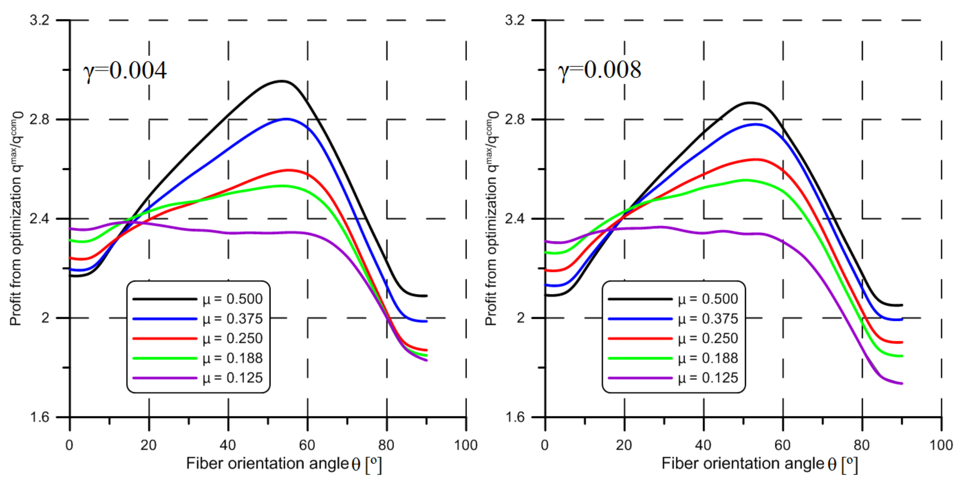
4.1. Composite Shell under Hydrostatic Pressure

The results of optimization in the case of the shell under hydrostatic pressure are collected in Table 2, Table 3 and Table 4 and Figure 3 and Figure 4. The determined optimal barrel shape geometries for the isotropic shell are summarized in Table 2. Generally, the optimal shape of the middle surface is far from the cylinder. It is worth noting here that starting from μ = 0.25 the inequality constraint (3), which limits the length of the radius of the shell at both ends is active, r(1) ≥ 0.5. The highest profit from optimization is observed for the shells for which the parameter μ is relatively large. Together with decreasing the value of ratio μ, the profit from optimization also decreases. However, in the case of μ = 0.25, the profit is slightly higher in comparison with the shell, where μ = 0.375. It can be explained by the fact, that for that structure (μ = 0.25) the character of the observed buckling pattern is changed, which is shown in Table 5.
In Table 5, the corresponding buckling patterns of the cylindrical references are also presented. For shorter shells, the half-waves are observed near both ends. For the longer structures, the buckling pattern is shifted to the center of the structure. Generally, the total number of half-waves for the optimal structure is over two times higher in comparison with the reference one. The obtained profit is also slightly higher for the thinner shells. It is worth stressing here that in the case of the shells of uniform thickness the observed values of h are not very far from the unity. Thus, the thicknesses of the real optimal structures do not vary significantly. Additionally, it should be stressed here that the profit from optimization qustb, computed under the assumption of the shell of uniform stability, is similar to that which is obtained for the shell of uniform thickness. This is an important conclusion from a practical point of view because the structure of uniform thickness is easier to manufacture.
In the next step of the proposed optimization procedure, the reference structure is changed. Now the reference shell is a cylindrical shell with such an angle-ply configuration for which the critical buckling load multiplier qcom0 reaches the lowest possible value. It occurred that the lowest value of qcom0 is always obtained for fiber orientation angle θ = 90°.
It should be noted here that the curves presented in Figure 3 and Figure 4 are prepared under the assumption that the optimal fiber orientation angle θ is observed for the shell, where the shape of the middle surface is determined previously in the first step of the optimization procedure for isotropic material.
Generally, the profit from optimization increases together with increasing ratio E1/E2. For E1/E2 = 17.573, the highest values of qmax/qcom0 ratio are observed for relatively short structures with parameters μ = 0.5, and μ = 0.375. However, in the case of E1/E2 = 3.415, the highest value of qmax/qcom0 ratio is obtained for the shell with parameter μ = 0.25. For these shells, the optimal fiber orientation angles θmax vary from 5° to 25°. In the case of longer structures μ < 0.375 the optimal angle θmax = 0°. In both cases of E1/E2 ratio, the profit form optimization is higher for the shells with parameter γ = 0.004. In comparison with the cylindrical shells (Table 3 and Table 4), the profit from optimization is over two times higher. Thus, one can say that the change of the shape of the middle surface has a decisive impact on the final results. The obtained buckling patterns of optimal structures are very similar to those which are presented in Table 4. Finally, it is worth stressing here that the obtained results, namely the values of qmax/qcom0 ratio, are significantly higher in comparison with the results which are presented for isotropic shells for all studied cases.

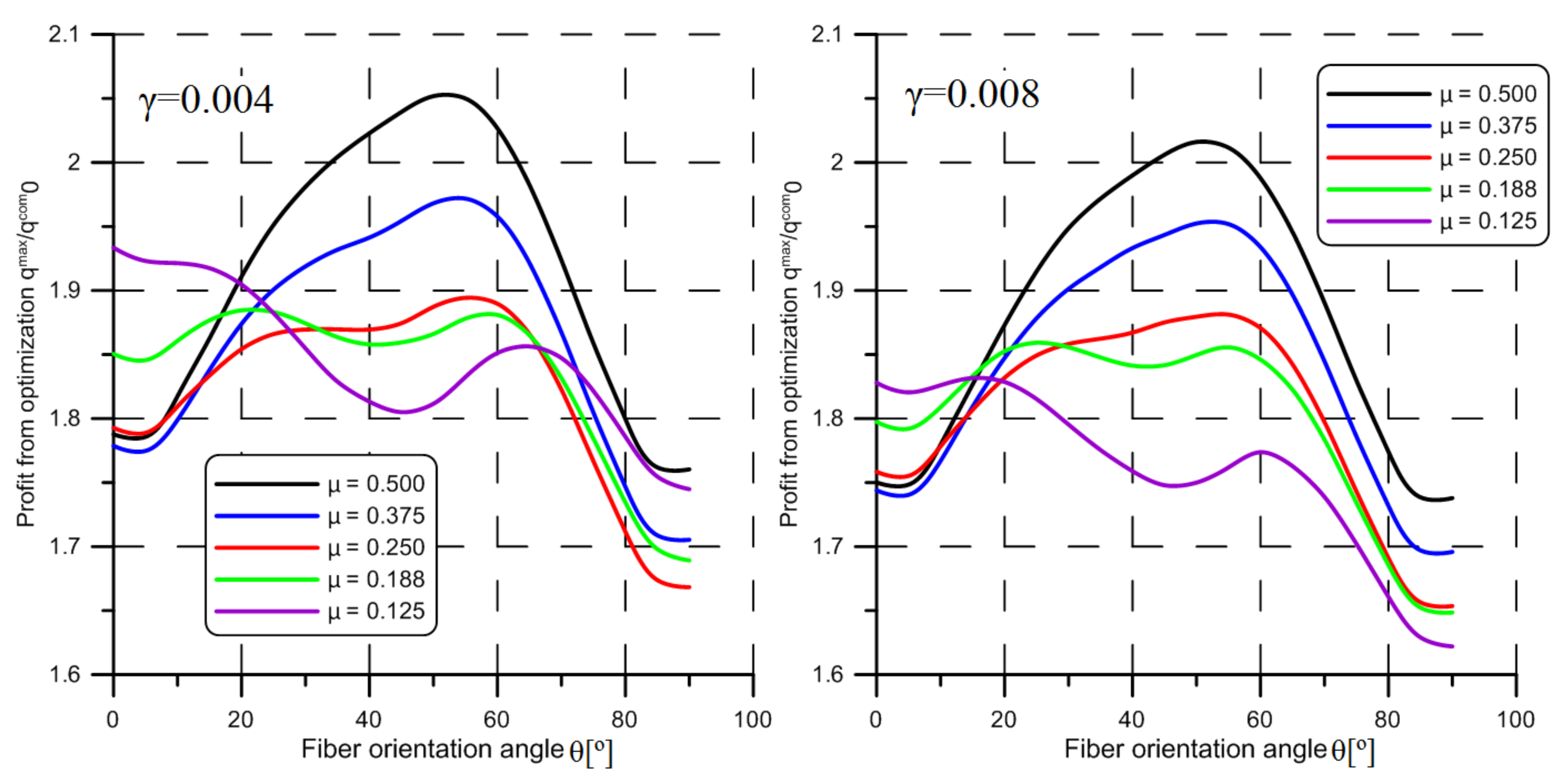
4.2. Composite Shell under Twisting

The results of optimization of the shell subjected to twisting are presented in Figure 5 and Figure 6 and Table 6, Table 7, Table 8 and Table 9. In the case of the shell of uniform thickness, the profit from optimization does not vary significantly with respect to parameter μ as well as γ and it does not exceed qmax/q0 = 1.712 (Table 6). In comparison with a shell under external pressure, the profit from optimization is much smaller. Moreover, to the contrary of the shell of uniform stability, together with decreasing parameter μ the profit from optimization slightly increases. A clear discrepancy between the shell of uniform thickness and the shell of uniform stability is observed. The results obtained for the shell of uniform stability are generally worse in comparison with the shell of uniform thickness. As is discussed in Appendix B, these discrepancies can be caused by a very rough estimation of membrane resultant stress caused by twisting. The wall thickness h, like previously in the case of the structure under external pressure, is also very close to unity. This fact is also very important from a practical point of view. For the shells, where μ ratio is equal to μ = 0.125 the wall thickness for the optimal structure is even slightly greater in comparison with the cylindrical reference shell.
The number of half-waves is much higher in the case of optimal structures in comparison with reference ones and the number of half-waves decreases together with the decreasing value of parameter μ. Similarly, as in the case of shells under external pressure, the number of half-waves observed for the optimal structure decreases together with an increasing value of γ. On the contrary of the structure under external pressure, all half-waves are localized at both ends of the shell, what is depicted in Table 9. The center of the structure seems to be unaffected by the buckling phenomenon. Finally, starting from μ = 0.188, the inequality constraint (3), where r(1) ≥ 0.5, is active for both values of parameter γ.
As before, in the case of the second step of the optimization procedure, where the optimal fiber orientation angle is looked for, it occurred that the lowest value of the critical load multiplier is obtained for cylindrical reference where the fiber orientation angle θ = 90° in all analyzed cases.
To the contrary of shells under hydrostatic pressure, in the case of shells under twisting the profit from optimization is the highest for the structures where the μ = 0.5 for all investigated cases. Generally, a clear maximum can be observed in Figure 5 and Figure 6, which correspond to the fiber orientation angle θmax = 50° or θmax = 55°. For the shells, where μ = 0.188, 125 the value of θmax is changing. The profit from optimization depends mainly on the ratio E1/E2. If the E1/E2 ratio is greater, the observed results are also higher. The impact of parameter γ on the results are not significant as in the case of shells subjected to hydrostatic pressure. In comparison with the cylindrical shells (Table 7 and Table 8), the profit from optimization is significantly higher.
Therefore, similarly to the case of shells under hydrostatic pressure, the change of the shape of the middle surface has a significant impact on the final results from optimization. Moreover, the obtained maximal values of qmax/qcom0 are higher in comparison with results, which are presented in the case of corresponding isotropic structures. Finally, as mentioned in the previous section, the buckling patterns of the optimal structures, which are made of composite material with optimal fiber orientation angle θmax, are very similar to those which are presented in Table 9. However, the number of half-waves varies significantly.

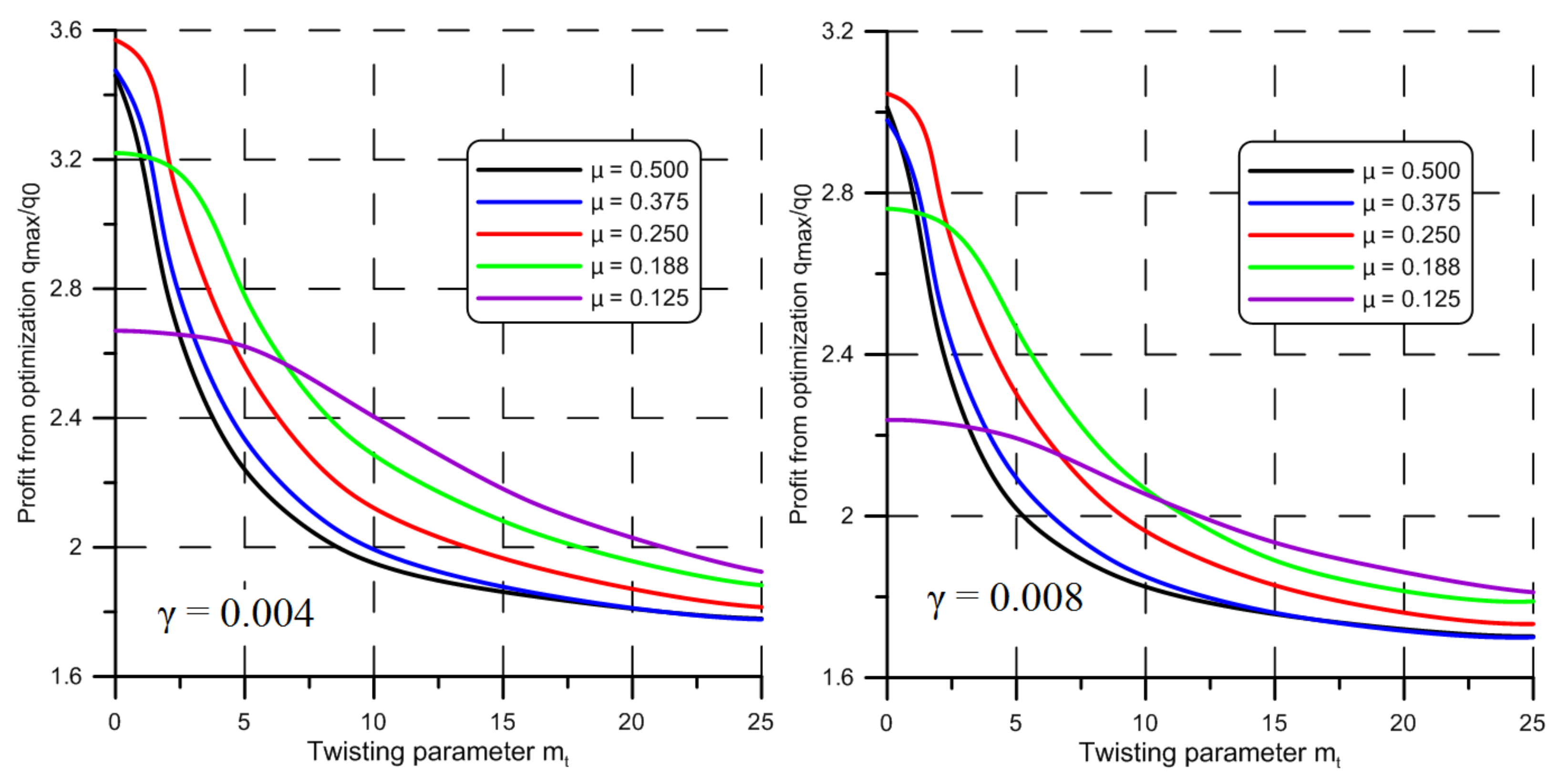
4.3. Shell under Combined Loadings

In the case of the shell structures subjected to combined loadings the main aim of carried out computations is to determine the impact of the gradually increasing twisting (the value of parameter mt) on the solution of the optimization problem. Taking into consideration the discrepancy between the analytical and numerical results observed for the shells of uniform stability (Appendix B) under pure twisting, the appropriate comparisons are not presented now. The calculations are made for isotropic metal shells and composite shells with mechanical properties described by the ratio E1/E2 = 17.573. The results obtained for the isotropic shells for parameter γ = 0.004 and γ = 0.008 and for different values of ratio μ are summarized in Figure 7. As can be observed (Figure 7), for the isotropic shells for which the ratio μ = 0.5, even a small contribution of twisting in combined loadings causes a visible reduction of the profit from optimization. In the case of the other investigated shells of uniform thickness, the obtained results are similar, which are depicted in Figure 7.
In the case of composite shells, the optimization is performed for two geometries defined by the parameters γ and μ. In the first case, in which the shell has shortened length, the parameters are equal to γ = 0.004 and μ = 0.5. For such geometry, there have been two optimal geometries of the barrel-shaped shell found (see Table 2 for pure hydrostatic pressure, and Table 6 for pure twisting). In the second case, in which the shell has a shape of a long pipe, the parameters are equal to γ = 0.008 and μ = 0.125. In this case, only one shape of the optimal shape is studied. As mentioned above, mt = 0 means that the studied shell is subjected to external pressure only. On the other hand, if the parameter mt → ∞, the profit from optimization, measured as qmax/q0, is expected to be identical, as in the case of pure twisting.
As can be observed in Table 10 and Table 11, the obtained results strictly depend on the magnitude of the applied twisting. In both cases of the set of geometrical parameters (γ and μ) together with the increasing value of mt (higher mt means greater influence of twisting) the value of the critical load for the reference structures also decreases. The profit from optimization in all analyzed structures also decreases. In the case of cylindrical shells, the profit obtained from optimization is almost identical and for the relatively small values of twisting the profit is over qcomcyl/qcom0 = 2 and together with increasing the twisting is below qcomcyl/qcom0 = 1.5 for μ = 0.125. However, a significantly different tendency is observed in the case of the optimal value of the fiber orientation angle θ. For the relatively small magnitude of twisting, the optimal fiber orientation angles are identical for studied cylindrical shells θcyl = 10° but for the more participation of the twisting, the tendency is different. In the case of shorter structures, the value of θcyl increases to 15° and in the case of the longer ones the θcyl decreases to 0°.
The change of the shape of the middle surface of the structure causes a further increase in the profit from optimization. It is worth noting that in the case of the shorter shells the obtained values of the ratio qmax/qcom0 are significantly larger in comparison with the longer ones. It should be stressed here that the optimal fiber orientation significantly differs for the structures where μ = 0.5 and μ = 0.125. In the first case, generally, the optimal fiber orientation angle is greater in comparison with those which are obtained in the latter case. For the shorter shells, the optimal value of θmax is about 55° whereas for the longer ones the value of θmax is almost constant and equal to 0°.
Finally, the shapes of the buckling patterns of the studied structures are presented in Table 12. Generally, it can be observed that in the case of cylindrical structures the buckling patterns obtained for all structures are very similar. The number of half-waves in the case of optimal cylindrical reference shells is generally greater in comparison with the optimal ones. However, in the case of shells of barrel shape, the buckling half-waves are generally localized in the neighborhood of the end caps of the structure. Therefore, the introduction of the variable thickness together with the change of the shape of the middle surface seems to be quite justified.

5. Conclusions

The presented work is devoted to the parametric optimization of axially-symmetric shells subjected to different loading conditions including pure external hydrostatic pressure, pure twisting, and a combination of external hydrostatic pressure and twisting. The proposed optimization procedure consists of two steps. In the first step, the optimal shape of the middle surface, as well as the constant uniform wall thickness, is looked for. In the next step, for the previously determined optimal shape of the middle surface, the optimal fiber orientation angle θ is determined. The obtained results can be summarized as follows:
  • The proposed optimization technique, based on splitting the procedure into two steps (the shape of the middle surface and the layer configuration are optimized separately), gives considerable benefits in the case of anisotropic structures subjected to combined loadings, and allows for the determination of more optimal geometries for all investigated loading conditions.
  • In the case of the isotropic structure under hydrostatic pressure, profit from optimization is the highest for structure, where μ = 0.5 and γ = 0.004. The obtained qmax/q0 ratio varies from 3.461 to 2.238.
  • In the case of isotropic shells subjected to pure twisting the profit from optimization varies insignificantly (from 1.712 to 1.619) and is smaller in comparison with shells under hydrostatic pressure. A very slight impact of parameters μ and γ on final results is observed.
  • Generally, in the case of composite shells, the profit from optimization is significantly higher as in the case of isotropic shells. For shells under hydrostatic pressure, the qmax/qcom0 ratio varies from 5.495 to 3.386 for E1/E2 = 17.573, and from 4.080 to 2.727 for ratio E1/E2 = 3.415. The value of parameters μ and γ as well as the E1/E2 ratio have a significant influence on the final results.
  • For the composite shells subjected to twisting the impact of the parameters μ and γ are not significant except the E1/E2 ratio. The obtained results vary from 2.951 to 2.366 for E1/E2 = 17.573, and from 2.052 to 1.832 for E1/E2 = 3.415. A clear maximum in the relationship between qmax/qcom0 ratio and the fiber orientation angle θ is observed.
  • In the case of structures subjected to combined load (external pressure and twisting), a significant profit of the application of the barrel-shaped shell is observed. A larger increase of this profit (qmax/qcom0 is from 5.359 to 2.951) is observed for shorter shells (γ = 0.004 and μ = 0.5). In the case of the longer shells, this profit is much smaller (from 3.386 to 2.366). Optimal fiber orientation angle θmax is significantly different in such cases.
  • In the case of the structures, where the participation of twisting is significant, it seems to be a justified extension of the optimization procedure by the introduction of the variable thickness as the additional design variable.

Author Contributions

Conceptualization, M.B.; methodology, M.B.; software, M.B.; data curation, M.B., and P.J.R.; writing—original draft preparation, M.B., and M.C.; writing—review and editing, P.J.R., and A.S. All authors have read and agreed to the published version of the manuscript.

Funding

This research received no external funding.

Institutional Review Board Statement

Not applicable.

Informed Consent Statement

Not applicable.

Data Availability Statement

Not applicable.

Conflicts of Interest

The authors declare no conflict of interest.

Appendix A

Below, concerning the discussed previously the formulation of the optimization problem, equality and inequality constraints (Section 2), all necessary relationships are shown. In the case of the equality constraint (1), the relationship describing the volume of material of the optimal structure and reference shell can be written as follows:
V m = 4 π H 0 L 0 2 R 2 d x = 2 π R 0 H 0 L 0 .
Next, the capacity of the optimal container is identical to the capacity of the reference structure constraint (2), namely:
2 π 0 L 0 2 R 2 d x = 2 π L 0 R 0 2 .
For further computations, the following dimensionless quantities are introduced:
μ = R 0 L 0 , γ = H 0 R 0 , ξ = 2 x L 0 , r = R R 0 , r 1 = R 1 R 0 , r 2 = R 2 R 0 , h = H H 0 , v m = V m 2 π L 0 R 0 H 0 , q c r = p c r 3 1 ν 1 2 2 E 1 γ , m t = M t π p 0 R 0 3 ,
where E1 and ν12 are the material properties shown in Table 1. Then, the equality constraints (A1) and (A2) in the dimensionless form can be rewritten as follows:
v m = h 0 1 r 2 d ξ = 1 , 0 1 r 2 d ξ = 1
Similarly, as above, the inequality constraints can be expressed in the dimensionless form as:
r ( 1 ) r a d m , r 0 , r 0 ,
where (‘) = d/, radm = Radm/R0, radm = μRadm. It is worth noting that the last constraint from (A5) is not taken into account in the current study.
In the dimensionless form the Equation (4), which describes the shape of the middle surface, takes the following form:
r ξ = r c 1 m ξ 2
The parameter rc denotes the radius of the middle surface measured in the middle of the shell rc = r(0). Its value can be determined with the use of equality constraint (A2). Substituting (A6) into the dimensionless form of (A2), the second relationship in (A4), the value of rc can be written as follows:
r 0 = 1 1 2 3 m + 1 5 m 2
Having completely defined the shape of the middle surface of the shell, the uniform constant thickness can be calculated with the use of equality constraint (A4):
h = 1 0 1 r 2 d ξ
Additionally, it is assumed that the minimum radius, the first inequality constraint in (A5), at the ends of the structure is restricted to r(1) = rmin ≥ 0.5. Finally, it should be noted here that for the shape of the middle surface, described by the expression (4), the rest of the inequality constraints in (A5) are also satisfied.

Appendix B. Local Stability Condition and Shell of Uniform Stability

The instability of thin-walled structures very often have a local character and the buckling does not depend essentially on the applied boundary condition. This is particularly true in the case of the ‘non-uniform’ geometry of a shell and the non-uniform state of stresses. In other words, instability can be determined by the stress state and the shape of a shell. The buckling phenomenon is initiated in the weakest zone of a structure. Here it is worth noting that if the thickness of the wall is relatively small in comparison with other dimensions, like the total length or diameter of a shell, the loss of stability can be more important in structural design than strength conditions. Some general theorems referring to the stability of elastic structures subjected to combined loadings are given by Papkovich [52]. One of them shows that for conservative loadings, the interaction surface is a convex one. Such a surface may also be constructed in the stress space:
F σ i σ i c r = 0
where σcri denotes critical stress. For the non-uniform stress distribution, the stresses in Equation (A9) may be considered maximal ones or stresses at certain points. Equation (A9) is called the local formulation of the stability condition. The optimization of shells with respect to their stability presents considerable difficulties connected with very complex stability equations, especially when both the middle surface and variable thickness are unknown, particularly in the case of non-uniform stress distribution. To avoid these difficulties a simplified local formulation of the stability condition should be introduced.
Making use of the hypothesis of the locality of buckling to the problem of optimal design, Życzkowski and Krużelecki [31] proposed a concept of the shell of uniform stability which can be stated as follows: if a condition of local stability is satisfied in the form of equality not only at a dangerous point but at any point of a shell, such a structure is called ‘the shell of uniform stability’.
However, in the case of a shell with a double curvature and non-uniform (lateral and longitudinal), stress distribution application of the stability condition in the form of the Equation (A9) is practically impossible because the critical stress σcri for an arbitrarily shaped shell (even for single stress) is usually unknown. In those cases, Equation (A9) should be replaced by more general ones allowing for analysis of an arbitrarily shaped shell. For a shell with a double curvature, Shirshov [48] transforms the problem of global stability to a simpler problem of the local stability of such a structure. Using the linear theory of shell stability, applying the equation given by Vlassov, and assuming a sinusoidal deflection mode over a small restricted area, Shirshov obtains a rather simple formula for the critical loading parameter q, namely:
q = 2 D E H K 1 cos 2 ϕ + K 2 sin 2 ϕ N ¯ 2 cos 2 ϕ + 2 S ¯ cos ϕ sin ϕ + N ¯ 1 sin 2 ϕ ,
where K1 and K2 denote meridional and circumferential curvatures, respectively. D stands for the shell stiffness, E is Young’s modulus and H is the wall thickness of the shell. The parameter ϕ is a certain variable with respect to which the critical loading multiplier q should be minimized. In Equation (A10) the membrane resultant stresses depend on q in the following way:
N 1 = q N ¯ 1 , N 2 = q N ¯ 2 , S = q S ¯ ,
where S is resultant stress due to twisting. Minimization of q with respect to ϕ leads to two solutions:
q 1 , 2 = 2 D E H K 1 z 1 , 2 2 + K 2 N ¯ 2 z 1 , 2 2 + 2 S ¯ z 1 , 2 + N ¯ 1 ,
where
z 1 , 2 = K 1 N ¯ 1 K 2 N ¯ 2 K 1 S ¯ K 1 N ¯ 1 K 2 N ¯ 2 K 1 S ¯ 2 + 4 K 2 K 1
The value of critical load multiplier q is determined by one of Equation (A12), whichever leads to a smaller value. The experimental results which confirm the hypothesis of the local stability condition in the case of the shell under different loading conditions are discussed in Ref. [49]. Here it is worth noting that using different governing stability equations, Axelrad [53] also obtained the formulae (A10) describing the critical membrane resultant stresses. In the case when the resultant stress S ≡ 0 the critical load multiplier q is described by simpler formulae, namely:
q 1 = 2 D E H K 2 N ¯ 1 , q 2 = 2 D E H K 1 N ¯ 2 , q = min q 1 , q 2
On the other hand, when N1 ≡ 0 and N2 ≡ 0 the critical load multiplier can be written as follows:
q = 2 D E H K 1 K 2 S ¯
In the case of axially-symmetric shell subjected to hydrostatic pressure and twisting the meridional resultant stress take the following form (Girkmann [54], Flügge [55]):
N 1 = p 0 R 2 2 R 2 R 2 R 01 2
where R01 means a radius of openings at the ends of a shell (R01 = 0 denotes closed ends of a shell). Next, taking into account the Laplace’s relation between the membrane meridional and circumferential resultants, namely:
N 2 = p 0 R 2 R 2 R 1 N 1
the hoop resultant takes the following form:
N 2 = p 0 R 2 p 0 R 2 2 2 R 1 R 2 R 2 R 01 2
Finally, the last resultant caused by twisting is:
S = M t 2 π R 2
where Mt is a twisting moment described by Equation (1). Substituting Equations (A16) and (A18), and (A19) into (A12), the function, which describes the variable wall-thickness H, can be obtained in the most general form. This function, given in the dimensionless form is presented below (Trzeciak [56]), namely:
h ξ = q c r r 2 r k r 2 r 01 2 + k 1 r 2 2 + k m t 2 r 2 2 ,
where
r 1 = 1 + 4 μ 2 r 2 3 2 4 μ 2 r , r 2 = r 1 + 4 μ 2 r 2 , k = r 1 r 2 , r 01 = R 01 R .
The sign ‘±’ means that among two possible values of h the appropriate is that which provides greater wall thickness. In the case of a shell subjected to hydrostatic pressure, the function describing the wall thickness h can be computed with the use of Equation (A20) with assumption mt = 0 or with the use of Equation (A14). The appropriate relationships take the following forms:
h ξ = q c r r 2 r r 2 2 k 1 + r 01 2 , N 2 = N c r , h ξ = q c r r 2 r r 2 r 01 2 , N 1 = N c r .
Finally, in the case of pure twisting, the wall thickness is described in the expression which can be obtained with the use of (1), (A15) and (A19):
h ξ = q c r r 1 r 2 1 4 r
For the shell of uniform stability, the equation describing the dimensionless volume of material vm takes the following form:
v m = 0 1 h ξ r 2 d ξ = 1
To verify discussed above analytical model of the shell of uniform stability, the advanced numerical procedure is proposed. This procedure is based on the finite element method and it consists of the following steps:
  • First of all, the maximal value of critical load multiplied and the corresponding shape of the middle surface of the shell is determined with the use of Equations (A6), (A7), and (A24). The variable wall thickness is described by one of the expressions (A20), (A22), or (A23) depending on which case of the load is studied.
  • The determined previously optimal shape of the middle surface is imported to the system of the finite element method. Next, the regular mesh, which consists of quadrilateral elements, is generated as shown in Figure 2. The size of the elements is assumed as le = L0/40.
  • It is assumed that the thickness in each finite element is constant and its value is computed with the use of the expression (A20), (A22), or (A23) in the point where ξ = (ξi + ξi + 1)/2, i = 1,2, …, 40. Of course, the mentioned coordinates ξi and ξi + 1 describe the X coordinate of the nodes which create each following ring of finite elements. For all these elements the wall thickness H is identical.
  • For such a finite element model the buckling analysis is performed. If the value of the obtained critical load multiplier is identical in comparison with the value computed with the use of analytical formulas described in Appendix B, which means that the analytical model provides reliable and accurate results.
The verification is performed for the isotropic shells subjected to pure external hydrostatic pressure and pure twisting. The obtained results are presented in Table A1 and Table A2. As can be observed in the case of pure external pressure the numerical and analytical results are relatively similar. It is worth noting that generally the loss of stability is caused by the circumferential resultant stress N2. However, in the case of the shell where μ = 0.5, there are the zones where the buckling is caused by the meridional resultant stress N1. The presented in Table A1 results are obtained for such structures where only circumferential resultant stress N2 causes the loss of stability in the whole shell. In other words, the critical load multiplier computed with the use of the case where N2 = Ncr always gives smaller values of qcr in comparison with the case where N1 = Ncr. Generally, the discrepancy does not exceed 2% in all investigated cases. However, in the case of pure twisting, a significant discrepancy is observed. This can be caused by the fact that the assumed approximation of the resultant stress S, Equation (A19), is very rough. Therefore, the comparison of the optimal solutions is presented only in the case of isotropic structures subjected to external pressure.
Table A1. Optimal shell of uniform stability under hydrostatic pressure.
μq0·10−6qustb/q0qmes/q0n/n0r(0)r(1)
γ = 0.004
0.5002.5003.9533.96170/161.1370.702
0.3752.1623.9343.94574/141.2160.500
0.2501.7733.5473.57342/101.2160.500
0.1881.5173.2333.26330/101.2160.500
0.1251.2232.7502.79120/81.2160.500
γ = 0.008
0.50011.8113.3473.35650/121.1370.702
0.37510.3643.2823.29352/121.2160.500
0.2508.4572.9753.00730/101.2160.500
0.1887.1152.7572.79812/81.2160.500
0.1255.9032.2792.32514/61.2160.500
Table A2. Optimal shell of uniform stability under twisting.
μq0·10−6qustb/q0qmes/q0n/n0r(0)r(1)
γ = 0.004
0.5007.8231.6111.81344/201.0930.803
0.3757.3681.5871.83942/181.1150.753
0.2506.7491.5752.01540/161.1700.619
0.1886.3291.5692.23738/141.2160.500
0.1255.7701.4742.12328/121.2160.500
γ = 0.008
0.50033.5521.5021.66930/161.0930.803
0.37531.6681.4871.76230/141.1260.728
0.25029.1291.4681.92830/121.1810.590
0.18827.3341.4532.08128/121.2160.500
0.12524.9281.3651.97820/101.2160.500

References

  1. Pan, B.B.; Cui, W.C. An overview of buckling and ultimate strength of spherical pressure hull under external pressure. Mat. Struct. 2010, 23, 227–240. [Google Scholar] [CrossRef]
  2. Zingoni, A. Liquid-containment shells of revolution: A review of recent studies on strength, stability and dynamics. Thin Wall. Struct. 2015, 87, 102–114. [Google Scholar] [CrossRef]
  3. Błachut, J.; Magnucki, K. Strength, Stability, and optimization of pressure vessels: Review of selected problems. Appl. Mech. Rev. 2008, 61, 60801. [Google Scholar] [CrossRef]
  4. Liu, P.; Kaewunruen, S.; Zhou, D.; Wang, S. Investigation of the Dynamic Buckling of Spherical Shell Structures Due to Subsea Collisions. Appl. Sci. 2018, 8, 1148. [Google Scholar] [CrossRef] [Green Version]
  5. Błachut, J. Buckling of cylinders with imperfect length. J. Press. Technol. 2014, 137, 011203. [Google Scholar] [CrossRef]
  6. Xue, J. Local buckling in infinitely, long cylindrical shells subjected uniform external pressure. Thin Wall. Struct. 2012, 53, 211–216. [Google Scholar] [CrossRef]
  7. MacKay, J.R.; Van Keulen, F.; Smith, M.J. the accuracy of numerical collapse predictions for the design of submarine pressure hulls. Thin Wall. Struct. 2011, 49, 145–156. [Google Scholar] [CrossRef]
  8. Błachut, J. Buckling of externally pressurized steel toriconical shells. Int. J. Press.Vessel. Pip. 2016, 144, 25–34. [Google Scholar] [CrossRef]
  9. Zhang, J.; Zhang, M.; Tang, W.X.; Wang, W.B.; Wang, M.L. Buckling of spherical shells subjected to external pressure: A comparison of experimental and theoretical data. Thin Wall. Struct. 2017, 111, 58–64. [Google Scholar] [CrossRef]
  10. Błachut, J. Experimental perspective on the buckling of pressure vessel components. Appl. Mech. Rev. 2013, 66, 11003. [Google Scholar] [CrossRef]
  11. Sato, M.; Wadee, M.A.; Iiboshi, K.; Sekizawa, T.; Shima, H. Buckling patterns of complete spherical shells filled with an elastic medium under external pressure. Int. J. Mech. Sci. 2012, 59, 22–30. [Google Scholar] [CrossRef] [Green Version]
  12. Shakouri, M.; Kouchakzadeh, M.A. Analytical solution for vibration of generally laminated conical and cylindrical shells. Int. J. Mech. Sci. 2017, 131–132, 414–425. [Google Scholar] [CrossRef]
  13. Krysko, V.A.; Awrejcewicz, J.; Saveleva, N.E. Stability, bifurcation and chaos of closed flexible cylindrical shells. Int. J. Mech. Sci. 2008, 50, 247–274. [Google Scholar] [CrossRef]
  14. Thompson, J.; Michael, T. Advances in shell buckling: Theory and experiments. Int. J. Bifurc. Chaos 2015, 25, 1530001. [Google Scholar] [CrossRef] [Green Version]
  15. Arbocz, J.; Starnes, J.H. Future directions and challenges in shell stability analysis. Thin Wall. Struct. 2002, 40, 729–754. [Google Scholar] [CrossRef]
  16. Błachut, J. On optimal barrel ‒ shaped shells under buckling constraints. AIAA J. 1987, 25, 186–188. [Google Scholar]
  17. Błachut, J. Combined axial and pressure buckling of shells having optimal positive curvature. Comput. Struct. 1987, 26, 513–519. [Google Scholar] [CrossRef]
  18. Błachut, J. Buckling of externally pressurised barrelled shells: A comparison of experiment and theory. Int. J. Pres. Ves. Pip. 2002, 79, 507–517. [Google Scholar] [CrossRef]
  19. Błachut, J. Optimal barreling of steel shells via simulated annealing algorithm. Comp. Struct. 2003, 81, 1941–1956. [Google Scholar] [CrossRef]
  20. Jasion, P.; Magnucki, K. Elastic buckling of barrelled shell under external pressure. Thin Wall. Struct. 2007, 45, 393–399. [Google Scholar] [CrossRef]
  21. Jasion, P. Stability analysis of shells of revolution under pressure conditions. Thin Wall. Struct. 2009, 47, 311–317. [Google Scholar] [CrossRef]
  22. Jasion, P.; Magnucki, K. Elastic buckling of horizontal barrelled shells filled with liquid—Numerical analysis. Thin Wall. Struct. 2012, 52, 117–125. [Google Scholar] [CrossRef]
  23. Magnucki, K.; Jasion, P. Analytical description of pre-buckling and buckling states of barrelled shells under radial pressure. Ocean Eng. 2013, 58, 217–223. [Google Scholar] [CrossRef]
  24. Krużelecki, J.; Stawiarski, A. Optimal design of thin-walled columns for buckling under loadings controlled by displacements. Struct. Multidiscip. Optim. 2010, 42, 305–314. [Google Scholar] [CrossRef]
  25. Zhang, J.; Wang, M.; Wang, W.; Tang, W. Buckling of egg-shaped shells subjected to external pressure. Thin Wall. Struct. 2017, 113, 122–128. [Google Scholar] [CrossRef]
  26. Zhang, J.; Hua, Z.; Tang, W.; Wang, F.; Wang, S. Buckling of externally pressurised egg-shaped shells with variable and constant wall thickness. Thin Wall. Struct. 2018, 132, 111–119. [Google Scholar] [CrossRef]
  27. Zhang, J.; Tan, J.; Tang, W.; Zhao, X.; Zhu, Y. Experimental and numerical collapse properties of externally pressurized egg-shaped shells under local geometrical imperfections. Int. J. Pres. Ves. Pip. 2019. [Google Scholar] [CrossRef]
  28. Sowiński, K. Buckling of shells with special shapes with corrugated middle surfaces—FEM study. Eng. Struct. 2019, 179, 310–320. [Google Scholar] [CrossRef]
  29. Rezaiee-Pajand, M.; Masoodi, A.R. Shell instability analysis by using mixed interpolation. J. Braz. Soc. Mech. Sci. Eng. 2019, 41, 419. [Google Scholar] [CrossRef]
  30. Rezaiee-Pajand, M.; Arabi, E.; Masoodi, A.R. Nonlinear analysis of FG-sandwich plates an shells. Aerosp. Sci. Technol. 2019, 87, 178–189. [Google Scholar] [CrossRef]
  31. Życzkowski, M.; Krużelecki, J. Optimal design of shells with respect to their stability. In IUTAM Symposium on Optimization in Structural Design; Sawczuk, A., Mróz, Z., Eds.; Springer: Warsaw, Poland, 1973; Berlin/Heidelberg, Germany; New York, NY, USA, 1975; pp. 229–247. [Google Scholar]
  32. Krużelecki, J.; Trzeciak, P. Optimal design of axially symmetrical shells under hydrostatic pressure with respect to their stability. Struct. Multidisc. Optim. 2000, 19, 148–154. [Google Scholar] [CrossRef]
  33. Życzkowski, M.; Krużelecki, J.; Trzeciak, P. Optimal design of rotationally symmetric shells for buckling under thermal loadings. J. Appl. Mech. 2001, 39, 443–455. [Google Scholar]
  34. Barski, M.; Krużelecki, J. Influence of a shearing force on optimal design of shells against buckling under overall bending. Eng. Optim. 2004, 36, 439–455. [Google Scholar] [CrossRef]
  35. Barski, M.; Krużelecki, J. Optimal design of shells against buckling by means of the simulated annealing method. Struct. Multidisc. Optim. 2005, 29, 61–72. [Google Scholar] [CrossRef]
  36. Barski, M.; Krużelecki, J. Optimal design of shells against buckling under overall bending and external pressure. Thin Wall. Struct. 2005, 43, 1677–1698. [Google Scholar] [CrossRef]
  37. Barski, M. Optimal design of shells against buckling subjected to combined loadings. Struct. Multidisc. Optim. 2006, 31, 211–222. [Google Scholar] [CrossRef]
  38. Muc, A.; Chwał, M.; Barski, M. Remarks on experimental and theoretical investigations of buckling loads for laminated plated and shell structures. Compos. Struct. 2018, 203, 861–874. [Google Scholar] [CrossRef]
  39. Barski, M.; Romanowicz, P. Natural frequencies and modal shapes of composite cylindrical panels with local damages. In Shell Structures: Theory and Applications—Proceedings of the 10th SSTA 2013 Conference; Gdańsk, Poland, 16–18 October 2013, Pietraszkiewicz, W., Górski, J., Eds.; Taylor &Francis Group: London, UK, 2014; Volume 3, pp. 277–280. [Google Scholar]
  40. Muc, A.; Bondyra, A.; Romanowicz, P. Buckling of composite multilayered shells—An experimental analysis. In Shell Structures: Theory and Applications—Proceedings of the 10th SSTA 2013 Conference; Gdańsk, Poland, 16–18 October 2013, Pietraszkiewicz, W., Górski, J., Eds.; Taylor & Francis Group: London, UK, 2014; Volume 3, pp. 227–230. [Google Scholar]
  41. Muc, A.; Stawiarski, A.; Romanowicz, P. Experimental Investigations of Compressed Sandwich Composite/Honeycomb Cylindrical Shells. Appl. Compos. Mater. 2018, 25, 177–189. [Google Scholar] [CrossRef] [Green Version]
  42. Stawiarski, A.; Chwał, M.; Barski, M.; Muc, A. The influence of the manufacturing constraints on the optimal design of laminated conical shells. Compos. Struct. 2020, 235, 111820. [Google Scholar] [CrossRef]
  43. Muc, A.; Chwał, M.; Romanowicz, P.; Stawiarski, A. Fatigue-Damage Evolution of Notched Composite Multilayered Structures under Tensile Loads. J. Compos. Sci. 2018, 2, 27. [Google Scholar] [CrossRef] [Green Version]
  44. Muc, A. Peculiarities in the Material Design of Buckling Resistance for Tensioned Laminated Composite Panels with Elliptical Cut-Outs. Materials 2018, 11, 1019. [Google Scholar] [CrossRef] [Green Version]
  45. Verchery, G. Design rules for the laminate stiffness. Mech. Compos. Mater. 2011, 47, 47–58. [Google Scholar] [CrossRef]
  46. Muc, A.; Chwał, M. Analytical discrete stacking sequence optimization of rectangular composite plates subjected to buckling and FPF constraints. J. Theor. Appl. Mech. 2016, 54, 423–436. [Google Scholar] [CrossRef] [Green Version]
  47. Vlassov, V.S. Allgemeine Schalentheorie und ihre Anwendung in der Technik; Akademie‒Verlag: Berlin, Germany, 1958; (translated from Russian, Moskva‒Leningrad 1949). [Google Scholar]
  48. Shirshov, V.P. Local buckling of shells. Soviet Appl. Mech. 1966, 2, 77–78. [Google Scholar] [CrossRef]
  49. Bushnell, D. Computerized Buckling of Shells. Mechanics of Elastic Stability 9; Martinus Nijhoff Publishers: Dordrecht, The Netherlands, 1985. [Google Scholar]
  50. Muc, A. Mechanika Kompozytów Włóknistych; Księgarnia Akademicka: Kraków, Poland, 2003. [Google Scholar]
  51. Bere, P.; Nemes, O.; Dudescu, C.; Berce, P.; Sabau, E. Design and analysis of carbon/epoxy composite tubular parts. Adv. Eng. Forum 2013, 8–9, 207–214. [Google Scholar] [CrossRef] [Green Version]
  52. Papkovich, P.F. Stroitelnaya Mekhanika Korablya, Ch. 2. (Structural Mechanics of a Ship), Part 2; Gos. Soyuz. Izd. Sudostr. Promyshl: Leningrad, Russia, 1941. (in Russian) [Google Scholar]
  53. Axelrad, E.I. On local buckling of thin shells. Int. J. Non Linear Mech. 1985, 24, 249–259. [Google Scholar] [CrossRef]
  54. Grikmann, K. Flächentragwerke, Einführung in die Elastostatik der Scheiben, Platten, Schalen und Faltwerke; Springer: Berlin/Heidelberg, Germany, 1954. [Google Scholar]
  55. Flügge, W. Statik und Dynamik der Schalen; Springer: Berlin/Heidelberg, Germany, 1957. [Google Scholar]
  56. Trzeciak, P. Optimal Design of Axially-Symmetric Shells of Uniform Stability Subjected to Combined Loadings. Ph.D. Thesis, Cracow University of Technology, Kraków, Poland, 2006. (in Polish). [Google Scholar]
Figure 1. Investigated shell under combined loadings.
Jcs 05 00128 g001
Figure 2. Finite element model of investigated shell for μ = 0.375, R(ξ = 0) = 1.153, m = 0.425.
Jcs 05 00128 g002
Figure 3. Optimization profit qmax/qcom0 as a function of fiber orientation angle θ, E1/E2 = 17.573.
Jcs 05 00128 g003
Figure 4. Optimization profit qmax/qcom0 as a function of fiber orientation angle θ, E1/E2 = 3.415.
Jcs 05 00128 g004
Figure 5. Optimization profit qmax/qcom0 as a function of fiber orientation angle θ, E1/E2 = 17.573.
Jcs 05 00128 g005
Figure 6. Optimization profit qmax/qcom0 as a function of fiber orientation angle θ, E1/E2 = 3.415.
Jcs 05 00128 g006
Figure 7. The profit from optimization qmax/q0 as a function of twisting parameter mt for metal optimal barrel.
Jcs 05 00128 g007
Table 1. Mechanical properties of applied materials [50,51].
MaterialE1 [GPa]E2 [GPa]G12 [GPa]ν12E1/E2
steel210.0210.080.770.301.000
carbon fiber/epoxy resin181.010.37.170.2817.573
glass fiber/polyester resin28.08.22.800.293.415
Table 2. Results of optimization for shell under hydrostatic pressure.
μq0·10−6qmax/q0qustb/q0hn/n0r(0)r(1)
γ = 0.004
0.5002.5003.4613.7670.93736/161.1150.753
0.3752.1623.4763.6930.93832/141.1590.647
0.2501.7733.5703.5470.96128/101.2160.500
0.1881.5173.2203.2330.98730/101.2160.500
0.1251.2232.6702.7501.00720/81.2160.500
γ = 0.008
0.50011.8113.0123.1890.93726/121.1150.753
0.37510.3642.9803.0820.93824/121.1590.647
0.2508.4573.0462.9750.96122/101.2160.500
0.1887.1152.7612.7570.98722/81.2160.500
0.1255.9032.2382.2791.00714/61.2160.500
Table 3. Results of optimization for composite shell under external pressure, E1/E2 = 17.573.
μγCylindrical PipeOptimal (Barrel) Shape
qcom0·10−6qcomcyl/qcom0θcyl [°] 1qmax/qcom0θmax [°] 1n/n0
0.5000.0040.7812.091105.4951522/20
0.3750.6832.08405.4571018/18
0.2500.5692.02805.460016/16
0.1880.4952.09954.785016/14
0.1250.4111.99603.903010/12
0.5000.0083.6592.12654.8512518/16
0.3753.2172.04504.7681514/14
0.2502.6552.06554.723012/12
0.1882.3531.99804.068010/12
0.1251.9382.189103.38608/10
1 layer orientations are defined as [−θ, +θ, −θ, +θ]S.
Table 4. Results of optimization for composite shell under external pressure, E1/E2 = 3.415.
μγCylindrical PipeOptimal (Barrel) Shape
qcom0·10−6qcomcyl/qcom0θcyl [°] 1qmax/qcom0θmax [°] 1n/n0
0.5000.0041.4891.36804.0801028/18
0.3751.3001.35704.140024/16
0.2501.0531.37704.354022/12
0.1880.9131.35703.880022/10
0.1250.7411.42303.210016/10
0.5000.0086.9491.37203.5791522/14
0.3756.0791.36403.609518/12
0.2505.0011.34803.719016/10
0.1884.3911.41003.238016/10
0.1253.5521.34502.727012/8
1 layer orientations are defined as [−θ, +θ, −θ, +θ]S.
Table 5. Buckling patterns of reference and optimal shells under external pressure, γ = 0.008.
Ref. Cylindrical
Metal Shell
Optimal Metal
Barrel Shell
Ref. Composite
Cylindrical
Shell θ = 90°
Optimal Composite
Barrel Shell
Jcs 05 00128 i001 Jcs 05 00128 i002 Jcs 05 00128 i003 Jcs 05 00128 i004
μ = 0.500
Jcs 05 00128 i005 Jcs 05 00128 i006 Jcs 05 00128 i007 Jcs 05 00128 i008
μ = 0.375
Jcs 05 00128 i009 Jcs 05 00128 i010 Jcs 05 00128 i011 Jcs 05 00128 i012
μ = 0.250
Jcs 05 00128 i013 Jcs 05 00128 i014 Jcs 05 00128 i015 Jcs 05 00128 i016
μ = 0.188
Jcs 05 00128 i017 Jcs 05 00128 i018 Jcs 05 00128 i019 Jcs 05 00128 i020
μ = 0.125
Table 6. Results of optimization for shell under twisting.
μq0·10−6qmax/q0qustb/q0hn/n0r(0)r(1)
γ = 0.004
0.5007.8231.6881.6110.95734/201.0930.803
0.3757.3681.6711.5870.96532/181.1130.753
0.2506.7491.6721.5750.97326/161.1700.619
0.1886.3291.7021.5690.98722/141.2160.500
0.1255.7701.7121.4741.00718/121.2160.500
γ = 0.008
0.50033.5521.6381.5020.95724/161.0930.803
0.37531.6681.6191.4870.95922/141.1260.728
0.25029.1291.6231.4680.97018/121.1820.590
0.18827.3341.6511.4530.98716/121.2160.500
0.12524.9281.6511.3651.00714/101.2160.500
Table 7. Results of optimization for composite shell under twisting, E1/E2 = 17.573.
μγCylindrical PipeOptimal (Barrel) Shape
qcom0·10−6qcomcyl/qcom0θcyl [°] 1qmax/qcom0θmax [°] 1n/n0
0.5000.0042.5351.695202.9515538/24
0.3752.4281.666152.8025536/22
0.2502.2971.61702.5965530/20
0.1882.2091.58902.5315524/18
0.1252.0861.54902.3861514/16
0.5000.00810.0831.715252.8645028/18
0.37510.2451.695202.7775526/18
0.2509.6271.651152.6365522/16
0.1889.2621.612102.5555016/14
0.1258.7751.58102.3663010/12
1 layer orientations are defined as [−θ, +θ, −θ, +θ]S.
Table 8. Results of optimization for composite shell under twisting, E1/E2 = 3.415.
μγCylindrical PipeOptimal (Barrel) Shape
qcom0·10−6qcomcyl/qcom0θcyl [°] 1qmax/qcom0θmax [°] 1n/n0
0.5000.0044.5521.23802.0525036/22
0.3754.3621.23301.9725534/20
0.2504.1001.22101.8945528/18
0.1883.9111.21401.8852020/16
0.1253.6021.21401.933016/14
0.5000.00819.2591.244202.0165026/16
0.37518.3681.24001.9525024/16
0.25017.2801.23201.8815520/14
0.18816.5621.21901.8592516/12
0.12515.5391.20701.8321512/12
1 layer orientations are defined as [−θ, +θ, −θ, +θ]S.
Table 9. Buckling patterns of reference and optimal shells under twisting, γ = 0.008.
Ref. Cylindrical
Metal Shell
Optimal Metal
Barrel Shell
Ref. Composite
Cylindrical
Shell θ = 90°
Optimal Composite
Barrel Shell
Jcs 05 00128 i021 Jcs 05 00128 i022 Jcs 05 00128 i023 Jcs 05 00128 i024
μ = 0.500
Jcs 05 00128 i025 Jcs 05 00128 i026 Jcs 05 00128 i027 Jcs 05 00128 i028
μ = 0.375
Jcs 05 00128 i029 Jcs 05 00128 i030 Jcs 05 00128 i031 Jcs 05 00128 i032
μ = 0.250
Jcs 05 00128 i033 Jcs 05 00128 i034 Jcs 05 00128 i035 Jcs 05 00128 i036
μ = 0.188
Jcs 05 00128 i037 Jcs 05 00128 i038 Jcs 05 00128 i039 Jcs 05 00128 i040
μ = 0.125
Table 10. Results of optimization for composite shell under combined loadings, γ = 0.004 and μ = 0.5 and E1/E2 = 17.573.
mtCylindrical PipeOptimal (Barrel) Shape:
rC = r(ξ = 0) = 1.115,
r(ξ = 1) = 0.753, m = 0.325
Optimal (Barrel) Shape:
rC = r(ξ = 0) = 1.093,
r(ξ = 1) = 0.803, m = 0.265
qcom0·10−6qcomcyl/qcom0θcyl [°]qmax/qcom0θmax [°] 1qmax/qcom0θmax [°] 1
00.7812.090105.495155.35910
0.50.7802.088105.221205.10915
10.7782.085104.988554.86560
20.7702.06954.616554.54260
50.7221.960103.872553.85355
90.6461.892153.476553.48555
150.5551.820153.249553.27455
250.4601.764153.101553.13555
∞-Pure
twisting
2.5351.695202.916502.95155
1 layer orientations is defined as [−θ, +θ, −θ, +θ]S.
Table 11. Results of optimization for composite shell under combined loadings, γ = 0.008 and μ = 0.125, E1/E2 = 17.573.
mtCylindrical PipeOptimal (Barrel) Shape:
rC = r(ξ = 0) = 1.216,
r(ξ = 1) = 0.500, m = 0.589
qcom0·10−6qcomcyl/qcom0θcyl[°] 1qmax/qcom0θmax [°] 1
01.9382.189103.3860
0.51.9372.189103.3850
11.9362.186103.3830
21.9292.18053.3720
51.8912.10003.3020
91.8081.95603.1460
151.6691.82502.9130
251.4661.72402.67815
∞-Pure
twisting
8.7751.58102.36630
1 layer orientations are defined as [−θ, +θ, −θ, +θ]S.
Table 12. Buckling patterns of reference and optimal shells under twisting, γ = 0.004.
Ref. Composite Cylindrical
Shell θ = 90°
Optimal. Composite
Cylindrical Shell
Optimal Composite
Barrel Shell
Jcs 05 00128 i041 Jcs 05 00128 i042 Jcs 05 00128 i043
mt = 0.5
Jcs 05 00128 i044 Jcs 05 00128 i045 Jcs 05 00128 i046
mt = 1
Jcs 05 00128 i047 Jcs 05 00128 i048 Jcs 05 00128 i049
mt = 2
Jcs 05 00128 i050 Jcs 05 00128 i051 Jcs 05 00128 i052
mt = 5
Jcs 05 00128 i053 Jcs 05 00128 i054 Jcs 05 00128 i055
mt = 15
Publisher’s Note: MDPI stays neutral with regard to jurisdictional claims in published maps and institutional affiliations.

