
The Design of Carbon Fibre Composite Origami Airbrakes for Endeavour’s Darwin I Rocket


School of Engineering, The University of Edinburgh, Edinburgh EH8 9AB, UK
*
Author to whom correspondence should be addressed.
J. Compos. Sci. 2021, 5(6), 147; https://0-doi-org.brum.beds.ac.uk/10.3390/jcs5060147
Submission received: 28 April 2021
/
Revised: 20 May 2021
/
Accepted: 28 May 2021
/
Published: 1 June 2021
(This article belongs to the Special Issue Geometrical and Structural Design of Load Bearing Composites)
Abstract
:This paper concerns the conceptual design of a carbon fibre composite airbrake intended for use on the Endeavour Darwin I rocket. The airbrake design is based on a Flasher origami model and we research its actuation mechanism, its ability to increase drag, and its mechanical behaviour when actuated. The aim of this work was to improve upon the current ‘Pancake’ airbrake model and we find that the origami Flasher generates six times more drag at a given torque. The Flasher is designed to be built of quasi-isotropic CFRP resting on a carbon fibre woven membrane. When subjected to distributed loads from drag, the Flasher presses into the membrane material causing it to stress at levels of 1.4 GPa. Taking into account a safety factor of 1.2 for the rocket airbrake, this stress lies far below the failure stress of the carbon fibre woven membrane. In this work, the composite Flasher origami airbrake design offers improvements in drag and weight reduction, and will withstand drag forces when actuated.
1. Introduction
1.1. An Introduction to Rockets, Dynamics, and Air Brakes
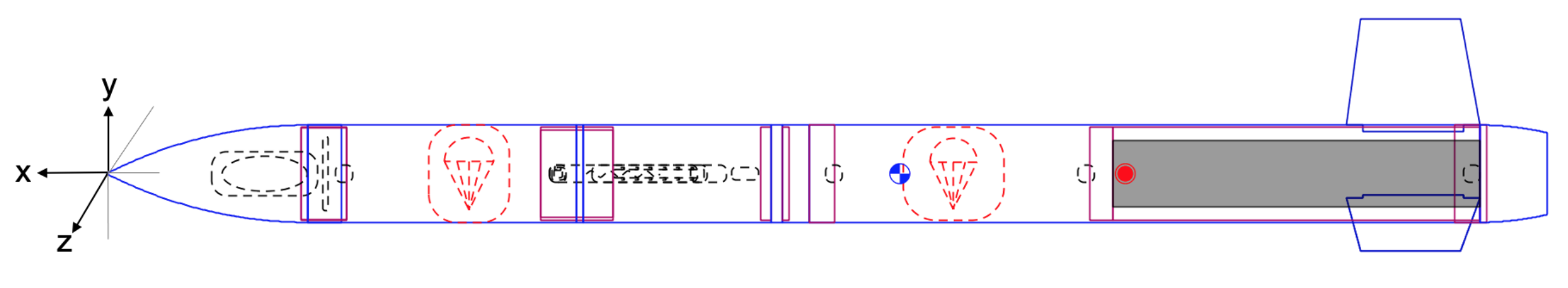
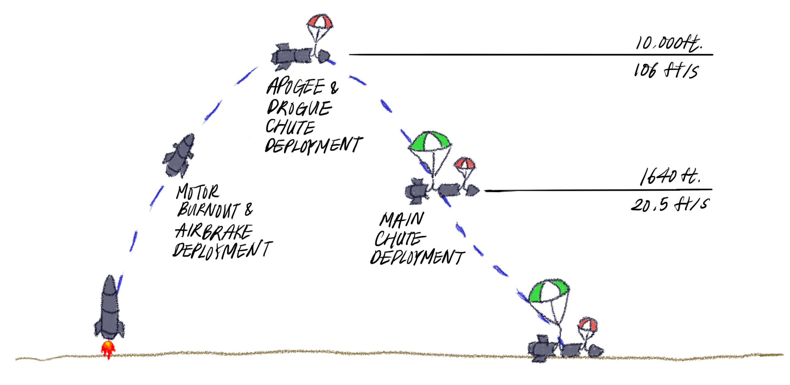
The flight path of a rocket can be broken down into four stages. At first, a rocket will launch, after which it experiences a powered ascent. Following its ascent until motor (propellant) burnout, it will begin coasting to its apogee, after which its final stage is parachute-deployment for the recovery of the rocket [1]. Endeavour is a rocketry team at The University of Edinburgh and the flight path planned for their Darwin I rocket, Figure 1, is shown in Figure 2. In Figure 1, the nose cone (left-most component) holds the payload, followed by the upper fuselage with the drogue chute, the avionics bay and the airbrake located just below, followed by the main chute, motor, fins, and the aft cone. The origin of the coordinate system is located at the tip of the nose cone, with x-axis along the length of the rocket and y- & z-axis normal to the fuselage. From Figure 2, as Darwin I reaches 2500 m after its powered ascent and subsequent burnout, it will be travelling at 250 m/s and will require the deployment of an airbrake to increase drag so that it may reach its target apogee of 3048 m. A few parameters of importance to the design of Darwin I airbrake are summarised in Table 1.
A stable rocket will be able to recover its nominal flight trajectory even when some disturbance acts upon it [1]. It will correct its non-zero angle of attack (AoA) from the disturbance through a corrective moment. The distance between the centre of mass () and centre of pressure () of a rocket is calculated to determine its stability. Often, this distance is shown as a multiple of its body diameter, with units of body calibre. A rocket is deemed stable if its is behind its , and as a general rule of thumb, the distance between the two should be between 1 and 2 calibres. The three main forces acting on a rocket are thrust of the motor, gravity, and the aerodynamic forces. The thrust is aligned with the velocity of the rocket, and produces no moments. Gravity acts on the of the rocket, and also produces no moments. Only the aerodynamic force produces normal forces and moments on the rocket body, thereby affecting its stability.
Vick [2] conducted a series of experiments on speed brakes with Mach Numbers ranging from 0.2 to 1.3 in fully developed turbulent flows. He investigated the effect of brake deflection angle, aspect ratio of brakes, brake chord height relative to boundary layer, and Mach number on drag. His findings are relevant to the airbrake as the geometry of the speed brake is similar to that of the airbrake. For all aspect ratios, the coefficient of drag () is dependent on the ratio of brake chord to boundary layer height, with the dependence growing stronger with reducing deflection angle. For a speed brake with a deflection of 90, Vick [2] showed that is independent of aspect ratio and that at a Mach Number of 0.678, the of a speed brake is 1.15. The boundary layer thickness at Mach Number 0.678 is 0.00279 m, or 2.79 mm (taken at a location where the velocity is 95% of the freestream). This value can be used to verify CFD simulation results, assuming fully developed turbulent flow. Flow before and after the airbrake can be approximated to flows over a forward-facing step and a backward-facing step. A forward-facing step is when the surface increases in height with respect to the free stream, and decreases for a backward-facing step. Both flow scenarios are nonlinear and can become unsteady [3]. The separation of flow due to the forward-facing step induces large vortex shedding and Kelvin–Helmholtz oscillation in the shear layer. In general, there are three flow regions: upstream, downstream, and the redevelopment regions. The upstream region is created due to the adverse pressure gradient before the step surface, and the downstream region is located over the leading edge of the step. Then, the flow reattaches to the step face in the redevelopment region. Zhu and Fu [4] investigated the forward-facing step in laminar free stream conditions. The numerical simulation conducted has shown that the step face amplifies the transition of boundary layer from laminar to turbulent. Here, the turbulence intensity parameter () is calculated according to Equation (1), where is the turbulent kinetic energy and u is the magnitude of the local velocity. Ref. [5] studied the turbulent subsonic flow over a backward-facing step. Similar to the forward-facing step, the flow is divided into three regions, with strong three-dimensional disturbances in the re-circulation region immediately after the step face, reattachment and settling of flow further downstream in the reattachment and transition region, and far downstream where the flow is relaxed and can be approximated as a two-dimensional flow.
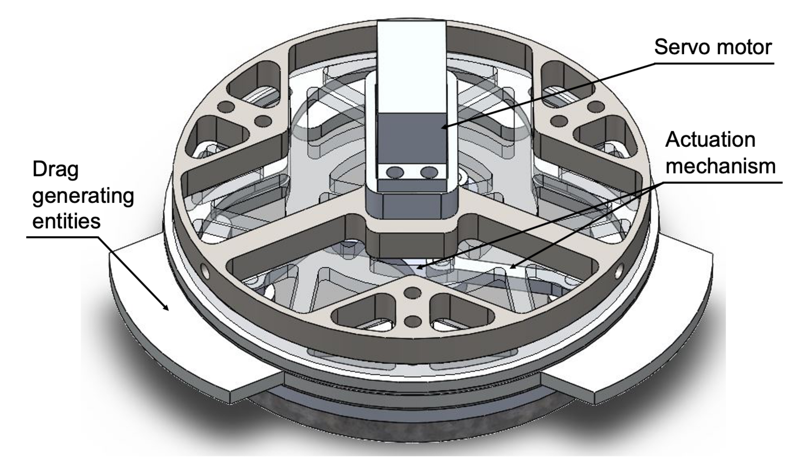
The current airbrake that has been designed for Darwin I is the ‘Pancake’, which utilises a servomotor and actuation mechanism to extend three drag generating surfaces beyond the circumference of the fuselage, Figure 3. The Pancake airbrake is designed to be manufactured using a combination of aluminium, mild steel and high density polyethylene (HDPE). While aluminium and mild steel are mechanically proficient materials, they are also high density and as such, will add undesirable weight to Darwin I. The Pancake design only generates 32 N of drag, which is close to ten times lower than the 305 N requirement for this rocket; however, if fully actuated from start to apogee, it will enable the rocket to reach its target apogee. It also requires 1.13 Nm torque to fully actuate, and its drag-to-torque ratio is, therefore, 28.3. The aims of this paper are redesign the Darwin I airbrake to (a) decrease the mass and volume of material whilst maintaining mechanical integrity used by using combinations of advanced composite materials and (b) increase the drag-to-torque ratio to improve the efficiency of drag generation by engineering lightweight composite folding mechanical metamaterials designed using principles inspired by the art of origami.
1.2. Origami Structures
Origami is an ancient art with deep-set Shinto and Buddhist roots. Movement in origami structures is enabled by spherical mechanisms around the vertices in fold intersections [6]. An origami pattern is composed of three components; faces (or panels), fold lines, and vertices that define the fold lines. Each fold is assigned a mountain or valley fold [7] with its own dihedral angle and fold angle. If a fold angle is positive (counter-clockwise rotation with respect to coordinate system), then it is a valley fold, and a mountain fold when it rotates clockwise [8]. In recent times, the diverse configurations of origami have been considered for use in innovative mechanical metamaterials with application potential within a plethora of engineering sectors [9,10,11,12,13]. The Miura-ori folding pattern has been of particular interest amongst researchers. Silverberg et al. [9], for example, used this pattern to create a mechanical metamaterial structure with a negative (in-plane) Poisson’s ratio and a positive Poisson’s ratio (with the same magnitude as the negative Poisson’s ratio) in bending. The engineering applications for a system like this are vast including, e.g., impact absorption, deployable structures, and more. Similar principles of structural design can be applied to other origami patterns to control mechanical properties. Jiang et al. [10] for example, designed octagonal building blocks with a Young’s modulus and Poisson’s ratio that could be fine-tuned as a function of the type of fold. Another Miura-ori application reported by Kshad and Naguib [11] was capable of self-deployment and retraction via a shape memory polymer. Boatti et al. [12] also used the Miura-ori fold but, in their work, to tune the thermal expansion behaviour, with possible applications in aerospace, optics, energy, and in microelectronics. Wang et al. [13] demonstrated that both electromagnetic behaviour and chirality, could be fine-tuned using Miura-ori folds.
The fold (i.e., hinge) is a vital component for actuation. In paper, a material with negligible thickness, the folds are a ideal line segments that act as a rotational hinge [8]. However, since a material with sufficient stiffness is required for the airbrake, it is most likely that the thickness of the panels will be non-negligible as thickness directly relates to stiffness [14]. Origami structures with non-zero thickness material are called rigid origami. Thickness-accommodating models adapt different techniques to allow the kinematics of rigid models to be as close to the zero-thickness (paper) model as possible [15]. Lang [14] conducted a review of various thickness-accommodating techniques and the manufacturability of them. The techniques mentioned are: tapered panel technique (embedded zero-thickness model), offset panel technique, hinge shift technique, membrane technique, doubled hinge technique, rolling contact technique, and strained joint technique [14]. Of particular interest to our work is the membrane technique as it can recreate the ideal hinges of the zero-thickness model through materials such as fabric. The membrane becomes a hinge with zero-thickness and can preserve the full range of motion of an origami pattern while achieving coplanar flatness. The minimum width of the membrane depends on the angle of the fold, with additional width depending on the required rigidity of the panel [14,15]. The limitations of this technique arise from the flexibility of the membrane material, which requires an understanding of the strain energy within the membrane for an accurate kinematic model. Further, numerical models for origami structures with membrane joints are useful tools in origami engineering and design [16].
1.3. Actuation of Origami Structures
Deployable origami structures can be divided into passive and active origami [8]. Passive origami is when the structure is deployed with a mechanical input (e.g., a servo), while active origami is actuated through non-mechanical fields/stimuli (electromagnetic, thermal, chemical). An airbrake designed through active origami could be actuated through shape transformations using, e.g., shape-memory alloys/polymers (SMA/SMP) activated by thermal stimuli, or using elastomers activated by changes in the electromagnetic field. Actuation with chemical fields would be difficult as it requires that the structure be submerged in liquid. SMAs are a group of alloys that returns to their ‘original shapes’ after thermally activated mechanical deformation. The temperature change required for this recovery depends on the alloy composition, ranging from 1 °C to 100 °C [17]. Wood [18] considered the application of SMA in a load-lifting and as supporting structures. SMA wires used in their tests were heated sequentially to lift a load, after which it would lock into a final configuration. The wires were placed strategically into folds with unique angles for each fold-configuration, enabling efficient actuation [18].
With passive origami, a gear train or a rotating mechanism with rods similar to a piston cylinder (as has been used in the Pancake airbrake described above) can be used. An actuation mechanism studied by Faist [19] is the Hoberman mechanism. It utilises rotation of a central ring to deploy the leaves of the solar panels attached to a CubeSat. The Hoberman mechanism allows the system to have one degree-of-freedom and, therefore, simplifies actuation. The Flasher is an origami structure that can be actuated and held in tension with a perimeter truss [20]. In this paper, the truss was driven by wires and motors, while torsion springs located at the joints enable effective deployment. Other methods mentioned by Zirbel [20] include pneumatic systems, centripetal acceleration with torsion springs, stored strain energy, and application of shape-memory polymer either as the main actuation mechanism or in view of aiding motion.
In this work, the origami Flasher was deemed a good origami candidate structure for an airbrake, as when closed (stowed) it is essentially a 3D structure that aligns flush with the fuselage of the rocket, while in its open state it becomes a flat 2D plate that extends beyond the diameter of the fuselage, enabling increased drag. We research these as composite structures attached to a perimeter truss that actuates passively.
2. Materials and Methods
The successful design of a composite airbrake requires several interconnected processes. These include rocket stability calculations, geometry definitions, materials selection, actuation mechanisms, drag computations and continuum mechanics computations.
2.1. Geometrical Modelling and Design
ORIPA [21] was used to create the patterns and observe their kinematics. Patterns generated from ORIPA were imported into the Origami Simulator [22] to compute axial strains during folding and strain release during unfolding, and to visualise the folding process. Origami Simulator is based on a numerical model that discretises the pattern into rigid truss linkages and computes the non-linear deformation during folding. The dimension of each panel of the Flasher can be calculated to confirm that the Flasher will provide sufficient drag. A Flasher with M = 6, H = 1, and R = 2 was used to utilise the motion of Flasher with minimum diameter allowed. Here, M, is the rotational order of the Flasher, H is the height order of the Flasher, and R is the number of rings in the Flasher. The membrane joint technique [14] was chosen as the hinge mechanism for the airbrake. As rapid actuation of varying magnitude is required, it is vital that the complete range of motion is conserved. The membrane joint also reduces design complexity and allows minimal joint mass and volume within structure. Further geometrical modelling of the Darwin I rocket including the Flasher, the membrane and the actuation system was conducted using SolidWorks (Dassault Systemes).
2.2. Design of the Actuation System for the Composite Flasher
An important factor to consider is the perimeter truss as it will enable actuation of the Flasher airbrake. As such, the perimeter truss design was focussed on the use of springs, connectors and cables. Both analytical calculations and numerical simulations were used in parallel to ensure confidence in the design. A perimeter truss with cables and springs was designed to actuate the airbrake. This allows the Flasher to be held in tension in any stage of its deployment and provides a method to integrate sections of the fuselage to the design to ensure that there are no protruding or concave surfaces when the Flasher is stowed [20]. There are a total of 12 truss members, each of which has to rotate according to the movement of the connectors with a bearing at the centre. Cylindrical roller bearings have higher axial displacement capabilities than ball bearings and, therefore, will be a better choice for connecting the truss members [23]. Universal joints are used to connect the Flasher and the perimeter truss as the outermost panels do not stay planar during deployment.
For the numerical simulations of the perimetere truss, we used RoboAnalyzer. RoboAnalyzer is a visualisation software developed by Gupta et al. for better visualisation of the kinematics of robots [24]. Symmetry in the truss was taken advantage of in order to simplify the simulated system. The dimensions, such as link length (truss member length) and the initial and final values of the joints, of the truss were used to set up the simulation. A prismatic joint was used to simulate the connectors moving vertically on the column and a revolute joint was used to mimic the motion of the truss member. Forward kinematics simulations were conducted assuming the truss reaches its maximum extension.
2.3. Stability Computations
While fuselage dimension and stability are the limiting factor of the dimension, the Flasher has to be sufficiently large to generate the required drag. Given that the kinetic energy of the rocket at the end of powered ascent has all dissipated at target apogee, the initial kinetic energy can be used to calculate the drag force D over distance from motor burnout to apogee d as shown below.
A parametric study of changing Flasher diameter was conducted to calculate the stability of the rocket with changing Flasher area. First, diameters ranging from 0.8 to 0.15 m were computed in 0.05 m increments in SolidWorks CFD (Dassault Systemes). The minimum gap size used to define the geometry of the model was set to be 0.6 m as it was important to include the full geometry of the Flasher and the rocket in normal force computations. The values of normal force and density of air were extracted to calculate the location of the centre of pressure for each Flasher area.
2.4. Materials Selection
An adequate material for the Flasher is a lightweight and stiff material as the panels will incur bending from the air flow and the kinematics of the rigid origami will need to be conserved. Both the panels and the membrane will need to resist shear to remain bonded during actuation and to ensure a reliable connection to the perimeter truss. Performance indices (PI) with a stiffness-limiting design were used to select materials on Ashby charts suitable for the panels and the membrane. The relevant PI for the airbrake and the membrane are shown in Table 2.
2.5. Aerodynamic Computations of the Composite Airbrake on Darwin I
SolidWorks CFD was used to simulate airflow around Darwin I with the Flasher airbrake under both actuated and stowed conditions. The structures were discretised using the Voronoi-Delaunay meshing scheme in SolidWorks. The Jacobian ratio check uses 6-points at the nodes, and an automatic mesh transition was used to optimise the mesh density. A curvature-based mesh was chosen to optimise the discretisation of Darwin I, since it was built as a multibody structure. Airflow over the rocket was modelled in this software using finite element solutions of the Navier–Stokes equations, Equation (2), in a three-dimensional Cartesian coordinate system, which is solved alongside the mass conservation constraint, Equation (3), assuming incompressbility. Here, is the directional velocity field vector, is a viscous stress tensor, g is a gravity component, is the fluid density, p is the pressure and t is the time.
2.6. Mechanical Modelling of the Composite Airbrake
The composite airbrake consisting of both the Flasher origami panels and the underlying membrane was also modelled in SolidWorks to determine the stress distributions of both the Flasher and the membrane, and to ensure that under the drag forces, there would be no likelihood of failure. A similar approach to discretisation was taken as in Section 2.5. Both parts were modelled in contact as elastic models using the properties of the composites selected for the study from the work based on Section 2.4. The Flasher was simulated with a force of 500 N normal to its face. The membrane-panel bonding was simulated as a bonded surface with incompatible mesh, with additional boundary conditions around the outer edges of the panels at the boundary of the Flasher to the membrane to properly define the panels. The edges of the membrane were defined as a fixed geometry to simulate the tension provided by the perimeter truss. In this model, stress is directly proportional to strain as shown by Figure 4, where is the total stress vector, is the elastic (isotropic, anisotropic, or orthotropic) material or material stiffness matrix, and is the total strain vector.
Drag forces calculated from the aerodynamic simulations were applied as distributed loads to the exposed posterior surfaces of the Flasher and membrane.
3. Results, Analyses and Discussion
3.1. Stability Computations
The drag force, D, requirement was calculated using and d as follows:
To locate the centre of pressure of the rocket, forces are normalised with dynamic pressure, reference area (fuselage area), and reference length (fuselage diameter) [1]. Normal force along the length of the rocket is calculated using Equation (5), where is the area at x, is the local downwash, is the normal force at xm away from the nose cone tip, is the free-stream velocity, is the angle of attack, is the normal force coefficient, is the reference area, and is the density. The normal force coefficient is calculated as shown in Equation (7).
Similarly, the corrective pitching moment can be calculated and normalised as shown in Equations (8) and (9) [1]. Here, is the pitching moment at xm from the nose cone tip, is the reference length, and is the pitching moment coefficient,
Both Equations (7) and (9) can be integrated over the length of the rocket to give the overall normal force coefficient and pitching moment coefficient [1]. The coefficients are then used to calculate the location of the centre of pressure, X, as shown in Equation (10) to evaluate the stability of the rocket.
Finally, stability is calculated according to Equation (11), where is the centre of gravity.
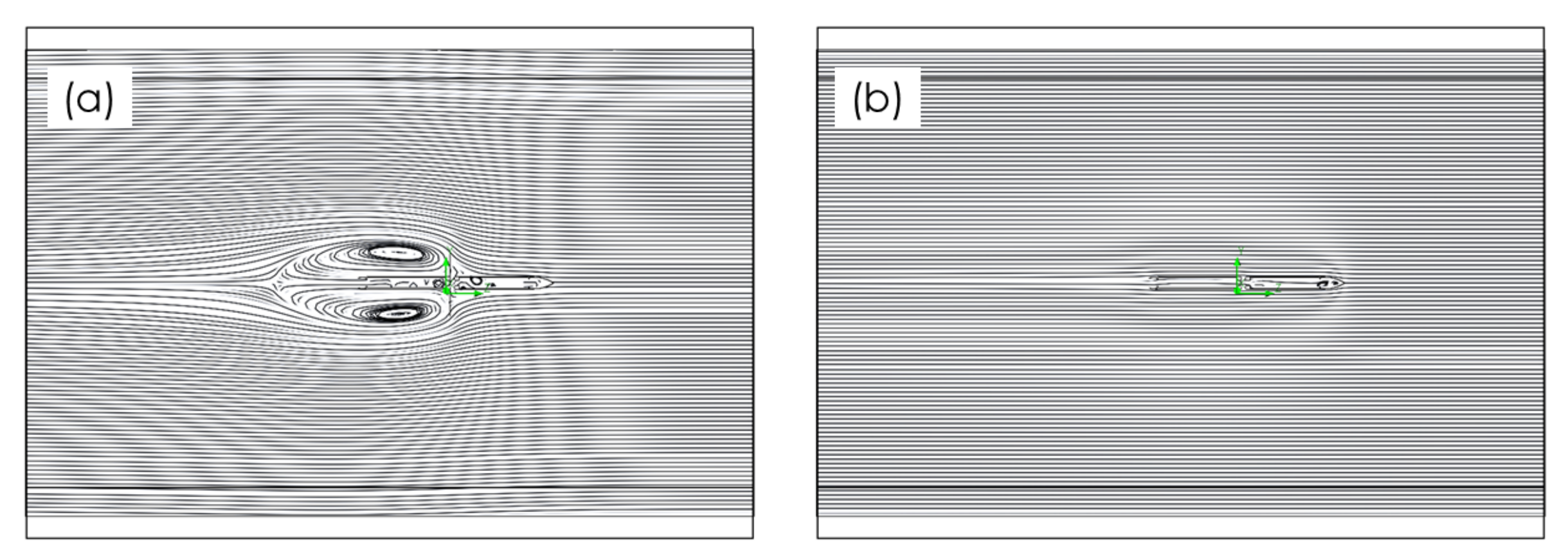
As seen in Figure 4, there is extreme flow re-circulation after the Flasher when its diameter is 0.8 m, whereas the flow is barely affected when the Flasher has a smaller diameter of 0.15 m. This is as expected since the rocket fuselage diameter is 0.14 m, and the airbrake would only extend to about 5 mm beyond the extents of the fuselage. The Flasher diameter is shown against rocket stability in Figure 5. The results show that the rocket becomes stable below a Flasher diameter of 0.25 m. The required extended diameter () for 1 calibre of stability is 0.21 m, and since this is the maximum diameter that gives the required minimum stability, the extended diameter of the Flasher is designed to be 0.21 m.
3.2. Geometrical Design and Actuation
Figure 6 show the geometrical relationships between panel sides ( and ) and the base hexagon side length (a). From and a, both and can be calculated (Equations (12)–(15)). Here, is the deployed Flasher diameter, a is the side length of the base hexagon, and and are the height and hypotenuse of the panel touching the base hexagon, respectively.
The final pattern of the Flasher is shown in Figure 7. Origami Simulator results (shown in Figure 8) show that the strain value at each hinge is different confirming that the best choice of joining was via a membrane as it can more easily accommodate for these variations in strain.
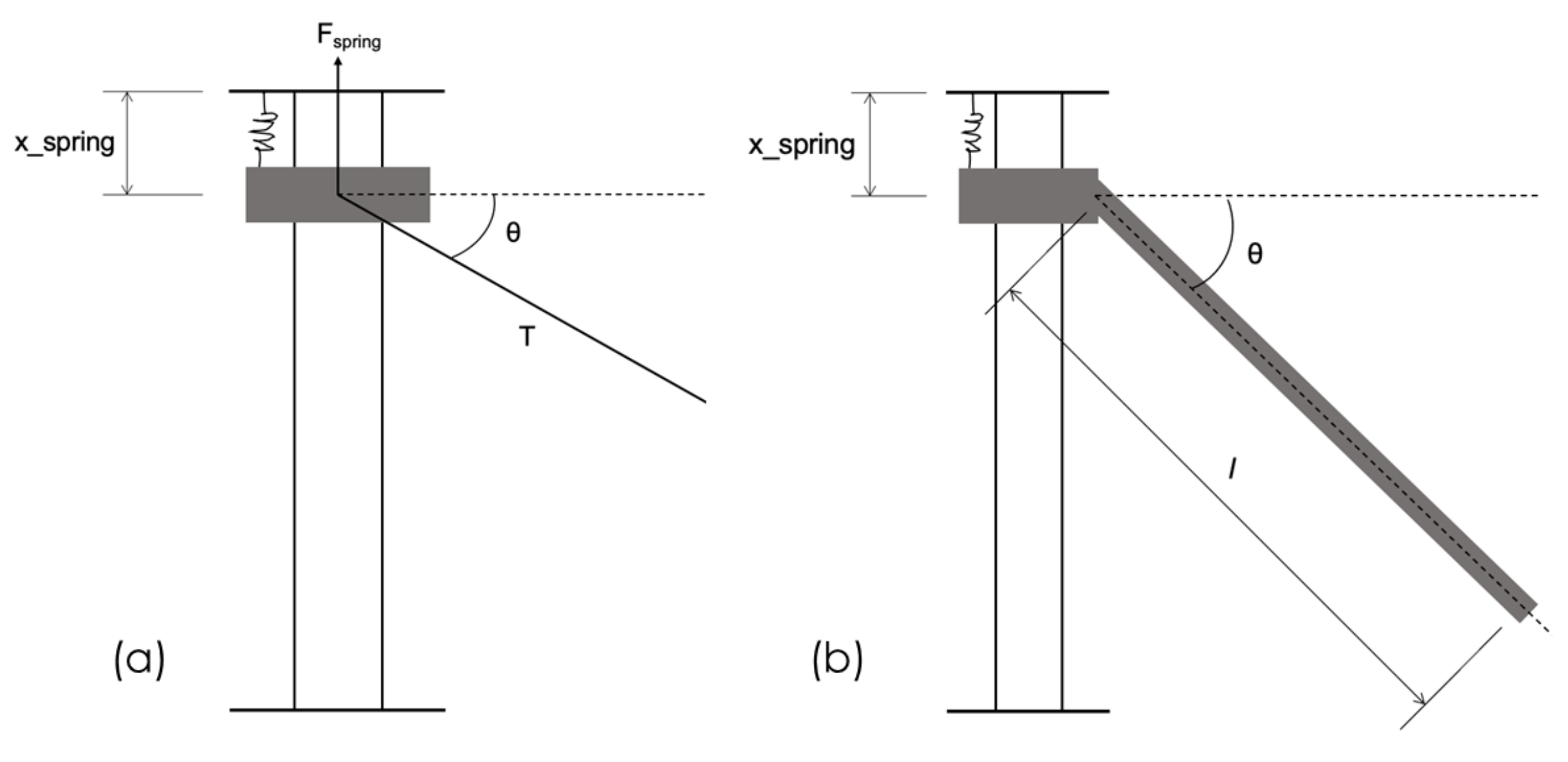
Figure 9a shows the free body diagram for a connector and the cable. The force from the spring, , must equal the vertical component of the tension of the cable, , Equation (16), where is the spring extension and k is the spring constant.
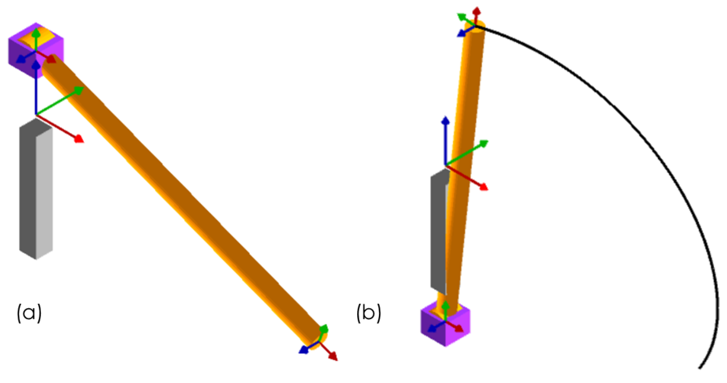
The derivation of the equation of motion of the truss member is shown in Equations (17) to (22), with , angle that the truss member makes with the connector, as the degree of freedom of the system [25], Figure 9b. Here, T is the kinetic energy of the system, is the mass of the connector, V is the potential energy of the system, is the spring extension, and l is the length of a truss member. The equation of motion cannot be linearised as the angles are too large for small angle approximations. These same members are also shown from the RoboAnalyzer kinematic simulations in Figure 10 at a start (a) and end (b) point.
The cables provide the tension needed to secure the perimeter truss and act as actuation mechanisms. As the cable retracts at the central mechanism, the Flasher deploys. The spring, attached to the top and bottom of the columns, acts against the tension, and as the cable unwinds, it pulls the connectors and retracts the airbrake. The spring is designed to be extended over approximately 3 cm. A suitable spring would be an extension spring with length of around 1.5 cm. Combining Equation (16) and (17) gives tension in terms of the length of the member and the spring constant. The maximum torque required for the central winding mechanism for the cable with a single connector can be calculated as shown below. The torque required is calculated to be 0.113 Nm for a single connector and 2.71 Nm for the perimeter truss using an extension spring with spring constant 0.407 N/mm [26] as an initial design choice.
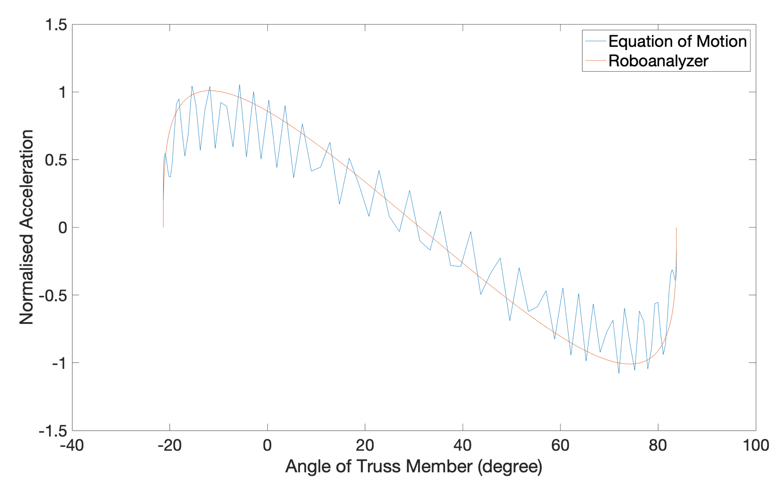
The normalised equation of motion values and the acceleration simulated from RoboAnalyzer are shown in Figure 11. As RoboAnalyzer requires only Denavit–Hartenberg parameters to compute the kinematics of the structure, normalisation aided in direct comparison for verification [24]. As shown, both analytical and numerical solutions show excellent agreement, which can, therefore, be used to calculate the tension and torque required for perimeter truss actuation for the Flasher airbrake.
3.3. Aerodynamics
With the dimensions of Flasher required for stable flight calculated, the drag generated from the diameter can be calculated as N, and this is found to be ca. 180 N higher than the required calculated drag force. As the Pancake (the current Darwin I airbrake design) generated around 32 N of drag in its fully actuated state, the Flasher airbrake is more effective in generating drag. The Pancake furthermore requires 1.13 Nm of torque for full actuation, which gives a drag-to-torque ratio of 28.3. The drag-to-torque ratio of the Flasher is around 179. As the Flasher generates more drag per torque applied, the Flasher is shown here to be more effective in generating drag.
3.4. Materials Selection
The PI guide was aimed at maximising strength and stiffness, and minimising mass. Most metals, elastomers, and engineering polymers were, therefore, immediately deemed unsuitable for application to the airbrake. Potential materials as recorded from an Ashby chart included aluminium, carbon-fibre-reinforced plastic (CFRP), and glass-fibre-reinforced plastic (GFRP). As noted earlier, resistance to shear deformation is also an important design consideration. The selection based on shear shows that carbon fibre and glass fibre are most suitable for application in the membrane. While not as critical for panel design, the strength PI index was also considered and yielded a similar result to the stiffness index. Table 3 provides details on the properties of materials selected based on the different PI identified. While continuous fibre uni-directional (UD) CFRP has superior properties in its fibre direction, it is weak transverse to the fibre direction. Surface pressures resulting from airbrake deployment necessitate materials that are equally stiff in several direction and for that reason, quasi-isotropic CFRP was the material of choice for the Flasher plates. Though the global properties of stiffness of quasi-isotropic CFRP are not as high as the axial stiffness values of UD CFRP, they are significantly higher than those of UD GFRP and more importantly, offer an orientation non-specific stiffness that is appropriate for application as the plates of an origami Flasher airbrake. These plates are not sufficiently flexible for use as membrane material and as such, between glass and carbon fibre woven textiles, carbon fibre woven is lower density and significantly higher in stiffness, and as such is our design recommendation for the membrane material. It is concurrently flexible enough in bending to enable effective mobility between the joints of the quasi-isotropic CFRP Flasher panels.
3.5. Thickness Determination of Composite Panels
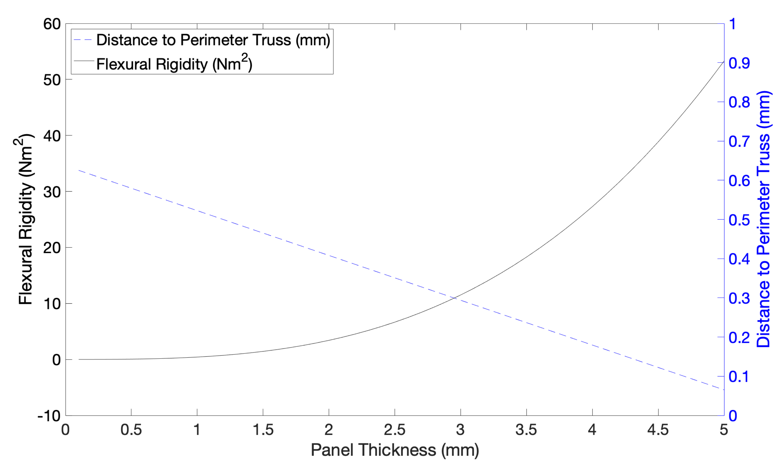
To approximate the optimal thickness in the design of the Flasher, analytical calculations were conducted approximating the exposed panel area to the shape of a cantilever beam and then calculating its flexural rigidity (). The moment of inertia () was calculated using Equation (23) (with b as an exposed length of 65 mm and h as a thickness). Here, is the Euler bending moment, is the deployed Flasher diameter, is the reference diameter, and w is is deflection. Figure 12 shows that the optimal thickness for the panels is 3 mm, which results in a flexural rigidity of 11.51 Nm. The dimensions of the Flasher are shown in Table 4 and based on these dimensions and the density of the materials used, we note that the Flasher is 79.5% lower in mass, and 71.5% lower in volume than the Pancake.
With the moment of inertia, the displacement at the end of the Flasher can be calculated using Equations (24) to (26), where is the Euler bending moment, flexural rigidity, w deflection, and moment of inertia of the beam.
3.6. Darwin I Build Including the Carbon Fibre Composite Origami Airbrake
Based on the findings and design parameters deduced thus far, the final design of the Darwin I rocket is shown in Figure 13, where both actuated and stowed positions are shown. The airbrake is visible in closer detail in Figure 14, again, in both actuated and stowed positions. In its actuated position in this figure, the origami Flasher is shown, under which the membrane is visible, and this is held and controlled by the perimeter truss, which can also be observed.
3.7. Aerodynamic Simulations of Darwin I with Airbrake Actuated
Both steady and transient flow simulations showed that the boundary layer before the Flasher is between 0.006 m and 0.038 m (Figure 15). The boundary layer thickness stays below 0.014 m until 0.3 m before the Flasher, then it starts to grow to 0.038 m. This is higher than that shown by Vick [2], which was 0.00279 m. A possible reason for this is that there is an abrupt increase in density and dynamic pressure just after the nose cone as seen in Figure 16, causing an alteration in the airflow behaviour, and thence no longer reaching fully developed turbulent flow.
Figure 17 shows the posterior-to-anterior velocity in the axial-direction (down the length of the rocket) displaying the posterior face of the Flasher. The Flasher is successful in reducing and reversing flow velocity, as can be observed by the red regions in the figure where the flow changes direction. This transient analysis (Figure 17) shows that fully opening the Flasher for a period of time increases the amount of airflow that the Flasher disrupts. Table 5 summarises key output parameters from the simulation.
3.8. Continuum Mechanics Simulations of Deployed Composite Airbrake under Drag
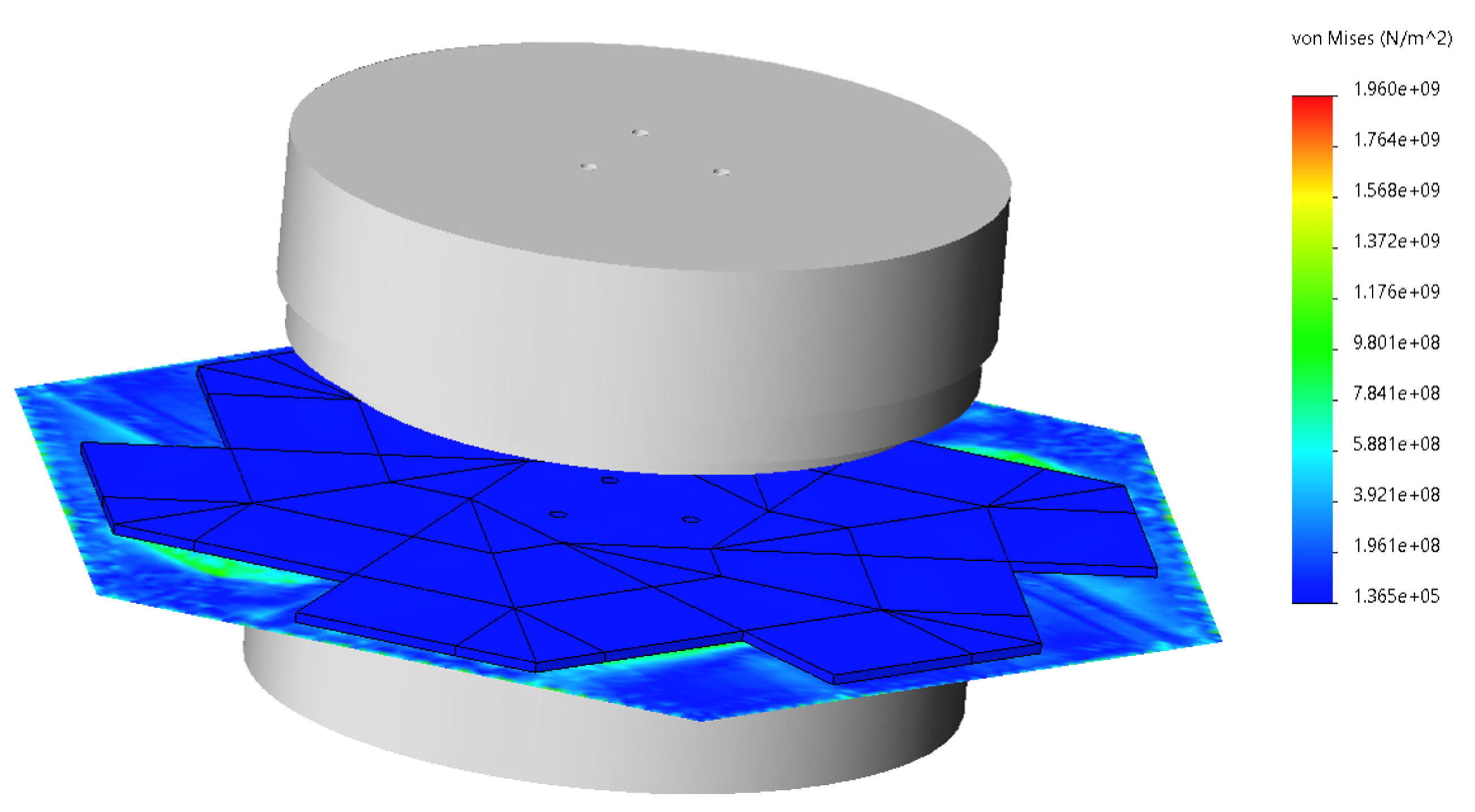
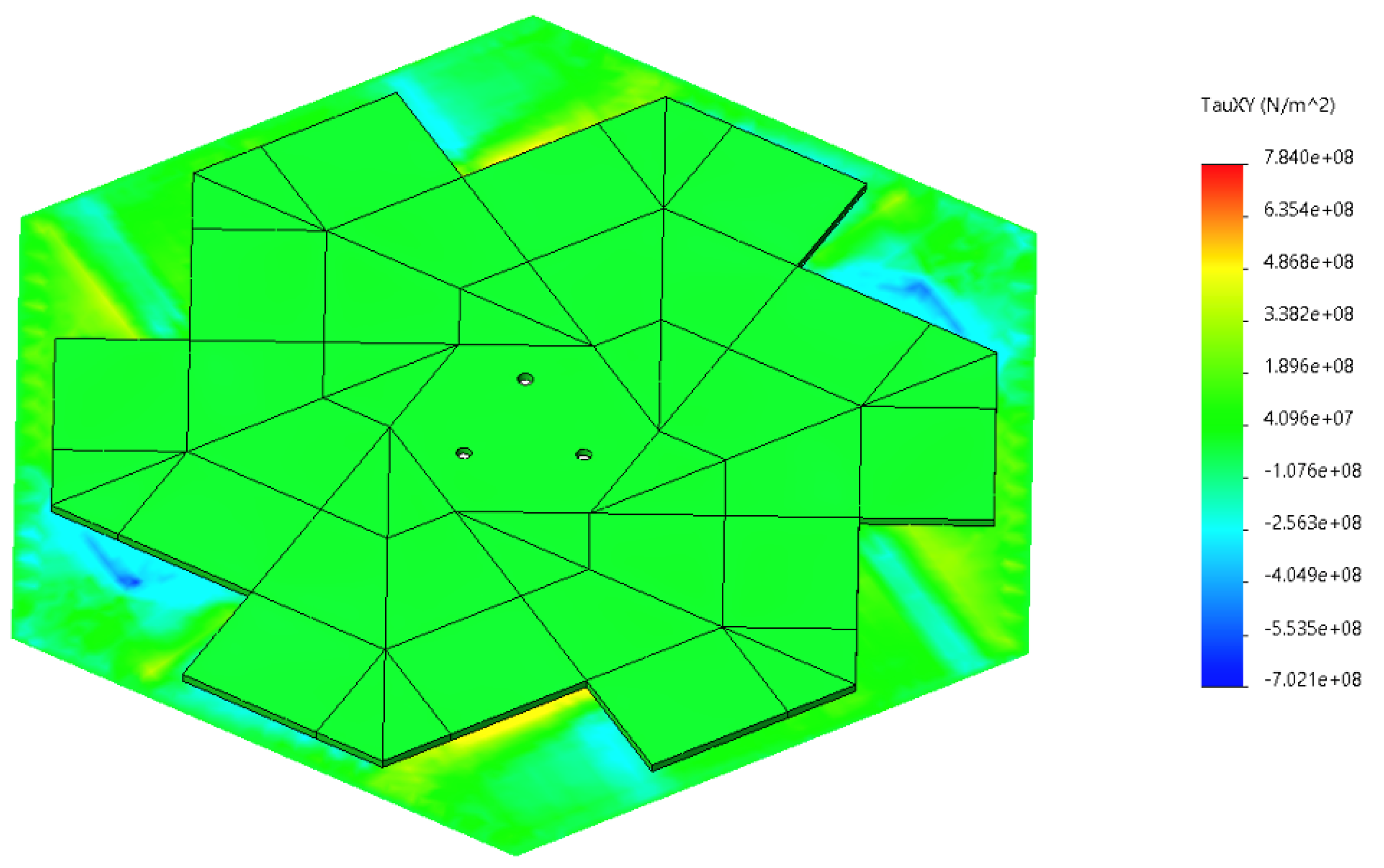
Figure 18 and Figure 19 show the results of the FEA and Table 6 provides the input parameters for both the quasi-isotropic CFRP origami Flasher panels, and the carbon fibre woven textile.
The maximum von Mises stress (Figure 18) that the Flasher experiences is around 1.4 GPa, which is below CFRP’s failure stress. Figure 19 shows the maximum shear stress that the Flasher experiences under load. The maximum value was 486.8 MPa, which is below the limit of the shear modulus of the Flasher. Endeavour’s safety factor for the airbrake is 1.2-fold the stress experienced. Therefore, even when including the safety factor, the membrane experiences 1.68 GPa of stress, which is at 47.6% of the failure strength of the carbon fibre woven textile. When considering the panels, the stress after incorporating the stress increase on application of the safety factor is 235 MPa, which is 36.5% of the failure strength of quasi-isotropic CFRP laminate. Both von Mises stress and shear stress was focussed at the Flasher-membrane boundary, which was to be expected due to the tension from the perimeter truss and the applied drag forces applied to the surface of the Flasher resulting in compression on the membrane surface under the panels, and shear at the edges of the panels on the surface of the carbon fibre woven membrane. The corners of the membrane displace by 0.226 mm. This edge displacement is very small in comparison to the effective length of the airbrake from the fuselage and as such, it is unlikely that there will be any significant loss in drag as a result of the composite materials bulging.
4. Conclusions
A carbon fibre composite origami-inspired airbrake was designed for Endeavour’s Darwin I rocket. The airbrake comprises two layers of carbon fibre composite. The anterior layer is a flexible carbon fibre woven membrane, while the posterior layer is quasi-isotropic carbon fibre reinforced plastic, segmented into separate panels that can fold and open using the anterior layer as a flexible hinge. This laminated composite structure benefits from both properties of strength and stiffness from the CFRP panels, and high levels of flexibility from the carbon fibre woven membrane. The combination of stiffness with flexibility between the joints allows the origami airbrake to unfold when actuated and to also resist deformation under drag, thereby enabling drag-based speed reduction of the rocket to target apogee. Importantly, the origami Flasher airbrake designed herein is significantly lighter and occupies less volume than the current Pancake airbrake design for the Darwin I, and is furthermore more effective at creating drag for the rocket exhibiting a drag-to-torque ratio > 6-fold higher than that of the Pancake airbrake.
Author Contributions
Conceptualization, H.L.; methodology, H.L. and P.A.; software, H.L.; validation, H.L.; formal analysis, H.L.; investigation, H.L.; resources, H.L. and P.A.; data curation, H.L.; writing—original draft preparation, H.L. and P.A.; writing—review and editing, H.L. and P.A.; visualization, H.L. and P.A.; supervision, P.A.; project administration, P.A. Both authors have read and agreed to the published version of the manuscript.
Funding
This research received no external funding.
Data Availability Statement
The data presented in this study are openly available in Edinburgh DataShare https://datashare.ed.ac.uk/handle/10283/3931, accessed on 15 June 2021.
Conflicts of Interest
The authors declare no conflict of interest.
References
- Niskanen, S. Development of an Open Source Model Rocket Simulation Software. Master’s Thesis, Helsinki University of Technology, Helsinki, Finland, 2009. [Google Scholar]
- Vick, A.R. An Investigation of the Drag Characteristics of Speed Brakes for Mach Numbers from 0.20 to 1.30; National Advisory Committee for Aeronautics: Houston, TX, USA, 1958. [Google Scholar]
- Graziani, A.; Lippert, M.; Uystepruyst, D.; Keirsbulck, L. Scaling and Øow dependencies over forward-facing steps. Int. J. Heat Fluid Flow 2017, 67, 220–229. [Google Scholar] [CrossRef]
- Zh, H.; Fu, S. Forward-facing steps induced transition in a subsonic boundary layer. Sci. China Physics Mech. Astron. 2017, 60, 712. [Google Scholar] [CrossRef]
- Gai, S.L.; Sharma, S.D. Forward-facing steps induced transition in a subsonic boundary layer. Phys. Fluids 1984, 27. [Google Scholar] [CrossRef]
- Bowen, L.A.; Grames, C.L.; Magleby, S.P.; Howell, L.L.; Lang, R.J. A classification of action origami as systems of spherical mechanisms. ASME J. Mech. Des. 2013, 135, 11. [Google Scholar] [CrossRef]
- Bern, M.; Hayes, B. The Complexity of Flat Origami. December 1996. Available online: https://www.osti.gov/biblio/416799 (accessed on 3 February 2021).
- Hernandez, E.A.P.; Hartl, D.J.; Lagoudas, D.C. Active Origami, 1st ed.; Springer International Publishing: Cham, Switzerland, 2019. [Google Scholar]
- Silverberg, J.L.; Evans, A.A.; McLeod, L.; Hayward, R.C.; Hull, T.; Santangelo, C.D.; Cohen, I. Using origami design principles to fold reprogrammable mechanical metamaterials. Science 2014, 345, 647–650. [Google Scholar] [CrossRef] [PubMed]
- Jiang, W.; Ma, H.; Feng, M.; Yan, L.; Wang, J.; Wang, J.; Qu, S. Origami-inspired building block and parametric design for mechanical metamaterials. J. Phys. Appl. Phys. 2016, 49, 315302. [Google Scholar] [CrossRef]
- Kshad, M.; Naguib, H. Characterization of origami shape memory metamaterials (SMMM) made of bio-polymer blends. In Behavior and Mechanics of Multifunctional Materials and Composites 2016; SPIE Digital Library: Bellingham, WA, USA, 2016; p. 98000H. [Google Scholar]
- Boatti, E.; Vasios, N.; Bertoldi, K. Origami Metamaterials for Tunable Thermal Expansion. Adv. Mater. 2017, 29, 1700360. [Google Scholar] [CrossRef]
- Wang, Z.; Jing, L.; Yao, K.; Yang, Y.; Zheng, B.; Soukoulis, C.; Chen, H.; Liu, Y. Origami-Based Reconfigurable Metamaterials for Tunable Chirality. Adv. Mater. 2017, 29, 1700412. [Google Scholar] [CrossRef] [PubMed]
- Lang, R.J.; Tolman, K.A.; Crampton, E.B.; Magleby, S.P.; Howell, L.L. A review of thickness-accommodation techniques in origami-inspired engineering. Appl. Mech. Rev. 2018, 70, 010805. [Google Scholar] [CrossRef] [Green Version]
- Zirbel, S.A.; Lang, R.J.; Thomson, M.W.; Sigel, D.A.; Walkemeyer, P.E.; Trease, B.P.; Magleby, S.P.; Howell, L.L. Accommodating Thickness in Origami-Based Deployable Arrays. ASME J. Mech. Des. 2013, 135, 111005. [Google Scholar] [CrossRef]
- Peraza Hernandez, E.A.; Hartl, D.J.; Lagoudas, D.C. Kinematics of Origami Structures With Smooth Folds. ASME J. Mech. Robot. 2016, 8, 061019. [Google Scholar] [CrossRef] [Green Version]
- Vaidyanathan, R. Kirk-Othmer Encyclopedia of Chemical Technology, 4th ed.; John Wiley and Sons, Inc.: Hoboken, NJ, USA, 2000; Volume 21, pp. 776–962. [Google Scholar]
- Wood, L.J.; Rendon, J.; Malak, R.J.; Hartl, D. An origami-inspired, sma actuated lifting structure. In Proceedings of the ASME 2016 International Design Engineering Technical Conferences and Computers and Information in Engineering Conference, Charlotte, NC, USA, 21–24 August 2016. [Google Scholar]
- Faist, K.A.; Wiens, G.J. Parametric study on the use of hoberman mechanisms for reconÆgurable antenna and solar arrays. In Proceedings of the 2010 IEEE Aerospace Conference, Big Sky, MT, USA, 6–13 March 2010; pp. 1–8. [Google Scholar]
- Zirbel, S.A.; Trease, B.; Magleby, S.; Howell, L. Deployment methods for an origami-inspired rigid-foldable array. In Proceedings of the 42nd Aerospace Mechanism Symposium, Baltimore, MD, USA, 1 May 2014. [Google Scholar]
- Mitani, J. Oripa: Origami Pattern Editor. 2012. Available online: https://mitani.cs.tsukuba.ac.jp/oripa/ (accessed on 24 April 2021).
- Tachi, T. Origami Software. 2020. Available online: https://origami.c.u-tokyo.ac.jp/%5C~%7B%7Dtachi/software/ (accessed on 24 April 2021).
- Cylindrical Roller Bearings. Available online: https://www.skf.com/uk/products/rolling-bearings/roller-bearings/cylindrical-roller-bearings (accessed on 3 February 2021).
- Gupta, V.; Chittawadigi, R.G.; Saha, S.K. RoboAnalyzer: Robot Visualization Software for Robot Technicians. In Proceedings of the Advances in Robotics (AIR’17), New Delhi, India, 28 June–2 July 2017; pp. 1–5. [Google Scholar]
- Lagrange, J. Analytical Mechanics; Springer Science and Business Media: Dordrecht, The Netherlands, 2013. [Google Scholar]
- RS Pro Stainless Steel Extension Spring, 22.1 mm × 3.2 mm. Available online: https://uk.rsonline.com/web/p/extension-springs/0821419/ (accessed on 24 April 2021).
- Eksi, S.; Genel, K. Comparison of mechanical properties of unidirectional and wovencarbon, glass and aramid Æber reinforced epoxy composites. Acta Phys. Pol. 2017, 132, 879–882. [Google Scholar] [CrossRef]
- 6082-t6 t651 Plate. 2021. Available online: https://www.aalco.co.uk/datasheets/Aluminium-Alloy_6082-T6~T651_148.ashx (accessed on 24 April 2021).
- Density of CFRP. Available online: https://www.easycomposites.co.uk/high-strength-carbon-fibre-sheet (accessed on 24 April 2021).
- Arao, Y.; Koyanagi, J.; Utsunomiya, S.; Takeda, S.; Kawada, H. Analysis of time-dependent deformation of a CFRP mirror under hot and humid conditions. Mech. Time-Depend. Mater. 2009, 13, 183–197. [Google Scholar] [CrossRef]
- Torayca t300 Fibre Data Sheet. Available online: https://media.easycomposites.co.uk/datasheets/T300DataSheet.pdf (accessed on 24 April 2021).
- Hamad, A. Size and shape effect of specimen on the compressive strength of HPLWFC reinforced with glass fibres. J. King Saud Univ. Eng. Sci. 2017, 29, 373–380. [Google Scholar] [CrossRef] [Green Version]
- Aamir, M.; Tolouei-Rad, M.; Giasin, K.; Nosrati, A. Recent advances in drilling of carbon fiber reinforced polymers for aerospace applications: A review. Int. J. Adv. Manuf. Technol. 2019, 105, 2289–2308. [Google Scholar] [CrossRef]
- Abdelal, G.; Barbero, E.; Robotham, A. Fatigue damage of composite structures applying a micromechanical approach. In Proceedings of the AES-ATEMA 2011 International Conference on Advances and Trends in Engineering Materials and their Applications, Milan, Italy, 4–8 July 2011. [Google Scholar]
Figure 1.
Endeavour’s Darwin I rocket layout and coordinate system.

Figure 2.
Planned flight path of Endeavour’s Darwin I rocket.

Figure 3.
The Pancake airbrake, the current design for Endeavour’s Darwin I rocket.

Figure 4.
Side view of streamline divergence by Flasher for parametric study of diameter. Streamline for Flasher with diameter at (a) 0.8 m and (b) 0.15 m.
Figure 4.
Side view of streamline divergence by Flasher for parametric study of diameter. Streamline for Flasher with diameter at (a) 0.8 m and (b) 0.15 m.

Figure 5.
Diameter of Flasher with respect to rocket stability.

Figure 6.
Geometrical relations in a section of Flasher. Blue line shows extended radius derived from stability vs. Flasher diameter (Figure 5).
Figure 6.
Geometrical relations in a section of Flasher. Blue line shows extended radius derived from stability vs. Flasher diameter (Figure 5).

Figure 7.
Fold pattern of Flasher. Blue lines show valley folds, red for mountain folds, and black show cut lines. Pattern created with ORIPA.
Figure 7.
Fold pattern of Flasher. Blue lines show valley folds, red for mountain folds, and black show cut lines. Pattern created with ORIPA.

Figure 8.
Strain at hinges when stowed (left) to deployed (right). Simulated in Origami Simulator.

Figure 9.
(a) Free body diagram for spring and tension and (b) Degree of freedom for one truss member.
Figure 9.
(a) Free body diagram for spring and tension and (b) Degree of freedom for one truss member.

Figure 10.
(a) Initial position of truss member in RoboAnalyzer and (b) Final position of truss member in RoboAnalyzer.
Figure 10.
(a) Initial position of truss member in RoboAnalyzer and (b) Final position of truss member in RoboAnalyzer.

Figure 11.
Normalised equation of motion for derived equation of motion and acceleration from RoboAnalyzer.
Figure 11.
Normalised equation of motion for derived equation of motion and acceleration from RoboAnalyzer.

Figure 12.
Thickness optimisation. Plot shows flexural rigidity and distance to perimeter truss as a function of panel thickness.
Figure 12.
Thickness optimisation. Plot shows flexural rigidity and distance to perimeter truss as a function of panel thickness.

Figure 13.
Actuated Flasher (top) and stowed (bottom) in Darwin I.

Figure 14.
Detailed view of actuated Flasher (left) and stowed (right).

Figure 15.
Boundary layer thickness from transient aerodynamic simulation.

Figure 16.
Density contour and dynamic pressure isoline from transient aerodynamic simulation.

Figure 17.
Contour plot of Velocity in the axial-direction of the Flasher in a transient aerodynamic simulation.
Figure 17.
Contour plot of Velocity in the axial-direction of the Flasher in a transient aerodynamic simulation.

Figure 18.
Von Mises stress of Flasher under 500 N on Flasher surface. Maximum von Mises stress in yellow-green areas. Bulkheads (grey components) included for context.
Figure 18.
Von Mises stress of Flasher under 500 N on Flasher surface. Maximum von Mises stress in yellow-green areas. Bulkheads (grey components) included for context.

Figure 19.
Shear stress of Flasher with 500 N of force normal to Flasher face. Maximum shear stress in yellow regions.
Figure 19.
Shear stress of Flasher with 500 N of force normal to Flasher face. Maximum shear stress in yellow regions.


Table 1.
A few parameters important to the design of Darwin I.
| Parameter | Value |
|---|---|
| Initial coasting velocity | 247.5 m/s |
| Initial coasting altitude | 1200 m |
| Initial coasting acceleration | −19.52 m/s |
| Length of rocket | 2.18 m |
| Mass of rocket | 18.4 kg |
| Diameter of rocket | 0.145 m |
| Target apogee | 3048 m (10,000 ft) |
| Reynolds Number | 3.21 × 10 |
| Mach Number | 0.678 |
Table 2.
Performance indices for material selection.
| Stiffness | Strength | Shear Modulus |
|---|---|---|
| Material | Density (kg/m) | Young’s Modulus (GPa) | Failure Strength (MPa) |
|---|---|---|---|
| Aluminium 6082-T6 | 2700 | 70 | 300 |
| CFRP (quasi-isotropic) | 1269 | 113.5 | 644 |
| GFRP (Uni-directional) | 1550 | 18.3 | 432 |
| Carbon fibre (Woven) | 1760 | 230 (Tensile) | 3530 (Tensile) |
| Glass fibre (Woven) | 2680 | 72 | 1700 |
Table 4.
Dimensions of the Flasher.
| Dimension | Value |
|---|---|
| Base hexagon side length (a) | 29.12 mm |
| Height of panel adjacent to base hexagon (x) | 16.81 mm |
| Hypotenuse of panel adjacent to base hexagon (y) | 58.24 mm |
| Folded height | 33.62 mm |
| Unfolded diameter | 210 mm |
| Exposed area () | 18,100 mm (0.0181 m) |
| Thickness (t) | 3 mm (0.0003 m) |
Table 5.
Transient CFD average values.
| Parameter | Value |
|---|---|
| Pressure (kPa) | 89.540 |
| Dynamic pressure (kPa) | 32.855 |
| Density (fluid) (kg/m) | 1.102 |
| Mach number | 0.712 |
| Turbulence intensity (%) | 4.231 |
| Dynamic viscosity ( Pa s) | 1.763 |
| Prandtl number | 0.708 |
Publisher’s Note: MDPI stays neutral with regard to jurisdictional claims in published maps and institutional affiliations. |
© 2021 by the authors. Licensee MDPI, Basel, Switzerland. This article is an open access article distributed under the terms and conditions of the Creative Commons Attribution (CC BY) license (https://creativecommons.org/licenses/by/4.0/).
Share and Cite
MDPI and ACS Style
Lee, H.; Alam, P. The Design of Carbon Fibre Composite Origami Airbrakes for Endeavour’s Darwin I Rocket. J. Compos. Sci. 2021, 5, 147. https://0-doi-org.brum.beds.ac.uk/10.3390/jcs5060147
AMA Style
Lee H, Alam P. The Design of Carbon Fibre Composite Origami Airbrakes for Endeavour’s Darwin I Rocket. Journal of Composites Science. 2021; 5(6):147. https://0-doi-org.brum.beds.ac.uk/10.3390/jcs5060147
Chicago/Turabian StyleLee, Hyeon (Ann), and Parvez Alam. 2021. "The Design of Carbon Fibre Composite Origami Airbrakes for Endeavour’s Darwin I Rocket" Journal of Composites Science 5, no. 6: 147. https://0-doi-org.brum.beds.ac.uk/10.3390/jcs5060147