Article

Effect of Twist Drill Geometry and Drilling Parameters on Hole Quality in Single-Shot Drilling of CFRP/Al7075-T6 Composite Stack

1
School of Mechanical Engineering, Universiti Sains Malaysia, Nibong Tebal 14300, Pulau Pinang, Malaysia
2
Laboratoire des Technologies Innovantes, UR UPJV 3899, Avenue des Facultés, Le Bailly, 80025 Amiens, France
*
Author to whom correspondence should be addressed.
J. Compos. Sci. 2021, 5(7), 189; https://0-doi-org.brum.beds.ac.uk/10.3390/jcs5070189
Submission received: 25 June 2021 / Revised: 12 July 2021 / Accepted: 14 July 2021 / Published: 17 July 2021
(This article belongs to the Special Issue Recent Advancements in Mechanical Drilling of Composite Laminates)

Abstract

:
Drilling two different materials in a layer, or stack-up, is being practiced widely in the aerospace industry to minimize critical dimension mismatch and error in the subsequent assembly process, but the compatibility of the drill to compensate the widely differing properties of composite is still a major challenge to the industry. In this paper, the effect of customized twist drill geometry and drilling parameters are being investigated based on the thrust force signature generated during the drilling of CFRP/Al7075-T6. Based on ANOVA, it is found that the maximum thrust force for both CFRP and Al7075-T6 are highly dependent on the feed rate. Through the analysis of maximum thrust force, supported by hole diameter error, hole surface roughness, and chip formation, it is found that the optimum tool parameters selection includes a helix angle of 30°, primary clearance angle of 6°, point angle of 130°, chisel edge angle of 30°, speed of 2600 rev/min and feed rate of 0.05 mm/rev. The optimum parameters obtained in this study are benchmarked against existing industry practice of the capability to produce higher hole quality and efficiency, which is set at 2600 rev/min for speed and 0.1 mm/rev for feed rate.

1. Introduction

A typical wide body aircraft requires at least 55,000 holes to be drilled for construction and assembly [1]. Holes’ quality and integrity is critical to the safety and reliability of aircraft, and must meet the stringent requirements of aircraft manufacturers as well as the aviation industry standards. Hence, the drilling method, tools and parameters selected are essentially important to ensure that the tight tolerance and requirements of aircraft assembly is being fulfilled. Of late, a single-shot drilling technique is increasingly applied on the metal and composite materials, such as aluminum and carbon fiber-reinforced polymer (CFRP), where both materials are stacked up and drilled in a single shot, to ensure perfect alignment and matching in the assembly process at a later stage, where aluminum and CFRP are stacked in layers forming the aircraft structure [2,3]. It is also the aim that the preceding processes should require minimum operational steps and reduced reworks, which greatly minimize production cost. The conventional drilling of polycrystalline diamond (PCD) drilling in the assembly of aircraft structures is being gradually replaced with single-shot drilling, mainly driven by the dire need to reduce drilling steps, which in return reduces the process, the amount of cutting tools to be used and there is an overall reduction in drilling cost [4,5]. It also promises better hole alignment and integrity. As such, the single-shot drilling technique is fast becoming a preferred choice for the drilling of aluminum-CFRP stack up [2,6].
Despite the progress made on the single-shot technique for stacked material drilling, the aviation industry still faces some challenges in producing optimum and consistent hole quality, which is critically required for safety and reliability. Besides holes having a relatively small and tight tolerance, the challenge imposed on the stacked-up materials is due to their vast difference and contrasting properties, where a compromising processing parameter is difficult to determine by the conventional approach. [7,8]. The significant difference in the properties of both metal and composites contribute to rapid tool failure and poor hole quality when both materials are drilled in a single shot, without proper guidance and a systematic approach [9,10]. On top of that, in current practice in the industry, the drilling process is carried out based on a trial-and-error method or is highly skill-dependent on the experience of the operators. This has contributed to inconsistency in holes’ tolerance and quality, which have resulted in high scraps, bringing about huge loss to the company. Statistically, it is reported that about 60% of the rejection are due to the defects in the holes [11].
Since CFRP composite material offers excellent strength to weight ratio, damage tolerance, fatigue and corrosion resistance, it is gradually replacing the conventional material and currently make up 50% of the structural weight of aircraft [12]. In order to facilitate component assembly, drilling is a common machining process. However, due to the property of alternately matrix and reinforcement materials of CFRP, the tool selection and machining parameters will largely correspond to the machining process quality [13,14]. In the research conducted by Phadnis et al. [15], thrust force, torque and delamination damage increase significantly with feed rate, but decrease gradually with increasing cutting speeds. Fernandes and Cook [16] studied the drilling of CFRP of varying thickness and found that chip formation during drilling operation caused high tool wear rates and subsequently increased drilling force. Qi et al. [17] showed that delamination-free holes can be obtained if the thrust force is maintained lower than a critical thrust force. Heisel and Pfeifroth [18] investigated the effect of varying point angles on the drilling of CFRP and proposed that a lower point angle will result in a smaller feed force.
The Al7075-T6 aluminum alloy, with zinc as the main alloying element, is commonly used in aircraft construction due to its strong and high strength advantage compared to many steels; it possesses good fatigue strength and average machinability [19,20]. Furthermore, Zitoune et al. [21] mentioned in their paper that the major problems arising in aluminum is the built-up edge (BUE) and burr at the exit side of the hole. However, BUE can be eliminated by increasing the spindle speed and the exit burr can be reduced if the feed rate is increased.
In most of the research, the study of critical thrust force is used as a benchmark to evaluate the drilling quality of stacked up materials. Zitoune et al. [21] found that the thrust force and torque during the drilling of CFRP/Al increase with the feed rate but decrease with spindle speed, similar to single material drilling. Moreover, the thrust force and torque during the drilling of Al compared to CFRP is doubled at a low feed rate (0.05 mm/rev) but tripled at higher feed rates (0.1 mm/rev and 0.15 mm/rev). This is because of the higher impact of the fiber and reduced effective clearance angles of the drill, thereby creating frictions between the CFRP/Al stack. Even so, it discussed when drilling stacked up materials, that machining demands higher feed rates in order to break up the chips and avoid the creation of burrs or built-up edge–built-up layer (BUE-BUL) [22].
Thrust force is the signature generated from a dynamometer at real time to monitor the drilling operation of the stacked-up materials. Based on various articles of the scientific literature [23,24,25,26,27,28,29,30], the thrust force recorded during the drilling of aluminum was found to be two to three times higher than those recorded during the drilling of the composite material. The thrust force generated while drilling CFRP is between 40 N and 300 N, while a range of 180 N to 658 N is recorded for the drilling of aluminum. Besides the mechanical properties of the stacked-up material, the thrust force is greatly influenced by the selection of parameters and tool geometries combination.
Montoya et al. [24] considered that abrasion was the strongest wear mechanism observed in CFRP/Al drilling, mainly due to the highly abrasive properties of carbon fiber. The CFRP damage at the hole entry is directly related to the aluminum chip evacuation. Zitoune et al. [27] found that the increase feed rate will lead to a significant increase in the value of the roughness, regardless of the type of drill used. In addition, Benezech et al. [31] concluded that the selected machining parameters have more influence on the surface roughness of CFRP than aluminum. This could be due to the isotropy property of the material [21].
Chip breakability is another factor which influences the quality of drilled holes. Zitoune et al. [25] mentioned that the feed rate and the drill diameter have a greater effect on chip breakability than spindle speed, due to the increase in cross sectional area of chip. Generally, discontinuous chips or small well-broken chips are preferable for aluminum because their small size allows them to move through the flutes more easily, decreasing the torque requirement and temperature and eventually reducing the risk of drill breakage. Moreover, the evacuation of aluminum chips directly affects the hole quality of CFRP, at the both the entry and wall of the hole [21], leading to the occurrence of peel up delamination at the top of the hole. The presence of continuous chips and accumulation of dust quantity in the air has been reported to reduce the efficiency of the vacuum system used for chip evacuation [25]. Hence, in order to maintain a sufficient hole quality for both aluminum and CFRP, the optimum parameter combination can be obtained with the use of lower feed rate. Both surface roughness and chip breakability are found to be highly dependent on the feed rate but not the spindle rate.
It is found that the hole diameter of metallic part is consistently larger than the composite. Zhang et al. [32] explained that the defects which are found in the CFRP holes are erosion, flash and tearing, whereas aluminum appears to have adhesive material and a large burr on the hole surface.
This paper aims to identify the optimum drill geometry and drilling parameters for stacked-up materials thanks to the thrust force signature. It could be used for process monitoring and active feedback for process improvement. This will also benefit the industry as the performance of drill bit and the drilling process can be measured based on real time, where instant feedback may be used to rectify onsite problem.

2. Materials and Methods

2.1. Worpiece Materials

Drilling tests were carried out on a CFRP and aluminum 7075-T6 (Al7075-T6) stack. The density of CFRP and Al7075-T6 was 1.601 g/cm3 and 2.597 g/cm3, respectively, and the hardness value of the former was 180 HV, while the latter was 250 HV. The composite specimen was 3.6 mm thick, made up of 26 plies of unidirectional carbon fiber and 2 plies of glass fiber, which were placed at the top and bottom of the laminate, joined together by carbon/epoxy prepregs. The cure ply thickness of carbon fiber and glass fiber were 0.125 mm and 0.08 mm each, respectively. The layer stacking was symmetric, with the sequence of [45/135/902/0/90/0/90/0/135/452/135]s. Meanwhile, the metal panel used was Al7075-T6, with the percentage of alloying elements as follows: Al~92.459, Mg~2.696 and Zn~4.845 wt%.

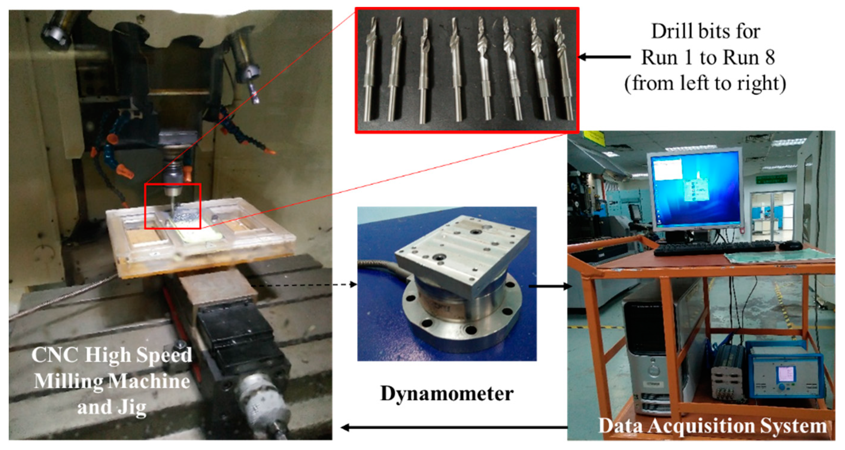
2.2. Cutting Tool and Force Measurement Setup

In this work, the twist drill bit was made of tungsten carbide with a composition of WC~ 93.36 and Co~6.64 wt%. It had a density of 14.35 g/cm3 and a hardness value of 1625 HV, both of which were significantly higher than the work-piece material. Six parameters with two levels (low and high) were studied in order to identify the optimum drilling parameters for stacked-up CFRP/Al 7075-T6 that complies with the specifications. The feed rate, spindle speed, helix angle, primary clearance, point angle and chisel edge angle were selected as the parameters for this study. The design of experiment (DOE) method was applied to simplify and eliminate the insignificant combination of parameters. Table 1 shows the combination of parameters for each run was generated based on L8 (26) fractional factorial design using Minitab 16. A total of 8 runs of experiments were conducted. Figure 1 shows the experimental setup for thrust force measurement for run 1 until run 8. Five holes (called Trials) were drilled for each experimental condition (called a Run) to reflect the quality of holes more accurately by taking the average readings besides monitoring the thrust force. For this experiment, 8 drill bits (one bit for each Run) with a bit diameter of 4.826 mm each were prepared based on the parameter combination.

2.3. Drilling Process

The drilling operation is carried out on CNC high speed milling machine, model Alpha T21iFB that manufacturer by FANUC CORPORATION (Yamanashi, Japan). Figure 1 shows the experimental setup of the drilling process with CNC milling machine, work-piece jig, dynamometer and data acquisition system. To acquire the thrust force signature during the drilling process of a stacked-up material, a dynamometer (Kistler 4 component dynamometer type 9272) was attached to the worktable of the CNC machine. When the force was detected during the drilling operation, the test data were transmitted to the data acquisition system. The data acquisition system consisted of a multichannel charge amplifier (type 5070) and Kistler DynoWare software (IMC Measurement and Control Version 3.2 Rev 2). After the four component sensors on the dynamometer transferred the charge signal to the multichannel charge amplifier, and the multichannel charge amplifier converted the resulting charge signal, which was proportional to the applied force, to voltage. The resulting signals were converted to force and torque by the calibrated data and were displayed in the software in the form of thrust force signature versus progression of drilling time.

2.4. Hole Integrity Assessment

Hole integrity assessment was carried out for hole diameter error and surface roughness. The hole measurement was performed using a coordinate measuring machine (CMM) model Crysta-Plus M443, and surface roughness was measured using a contact roughness tester (Surftest SV-3100). Both equipment was supplied by Mitutoyo America Corporation, Aurora, Illinois. For hole measurement, four points along the hole circumference were taken by placing the probe at the midpoint of the hole thickness for CFRP and the Al7075-T6 aluminum panel, respectively. Diameter error was determined from the difference between nominal and measured value.
Surface roughness measurement was performed on a cut-off wavelength of 0.8 mm and an evaluation for measurement in thickness direction of 1.6 mm. Roughness measurement was repeated four times for each hole and the average value was taken.

2.5. Chip Observation

Chip formed during the drilling is an important indicator of the tool–material interaction and the resulting force during the drilling process. In this work, chip formed during the drilling was observed using an optical microscope of magnification 25× and the chips were categorized according to their different characteristics form.

3. Results and Discussion

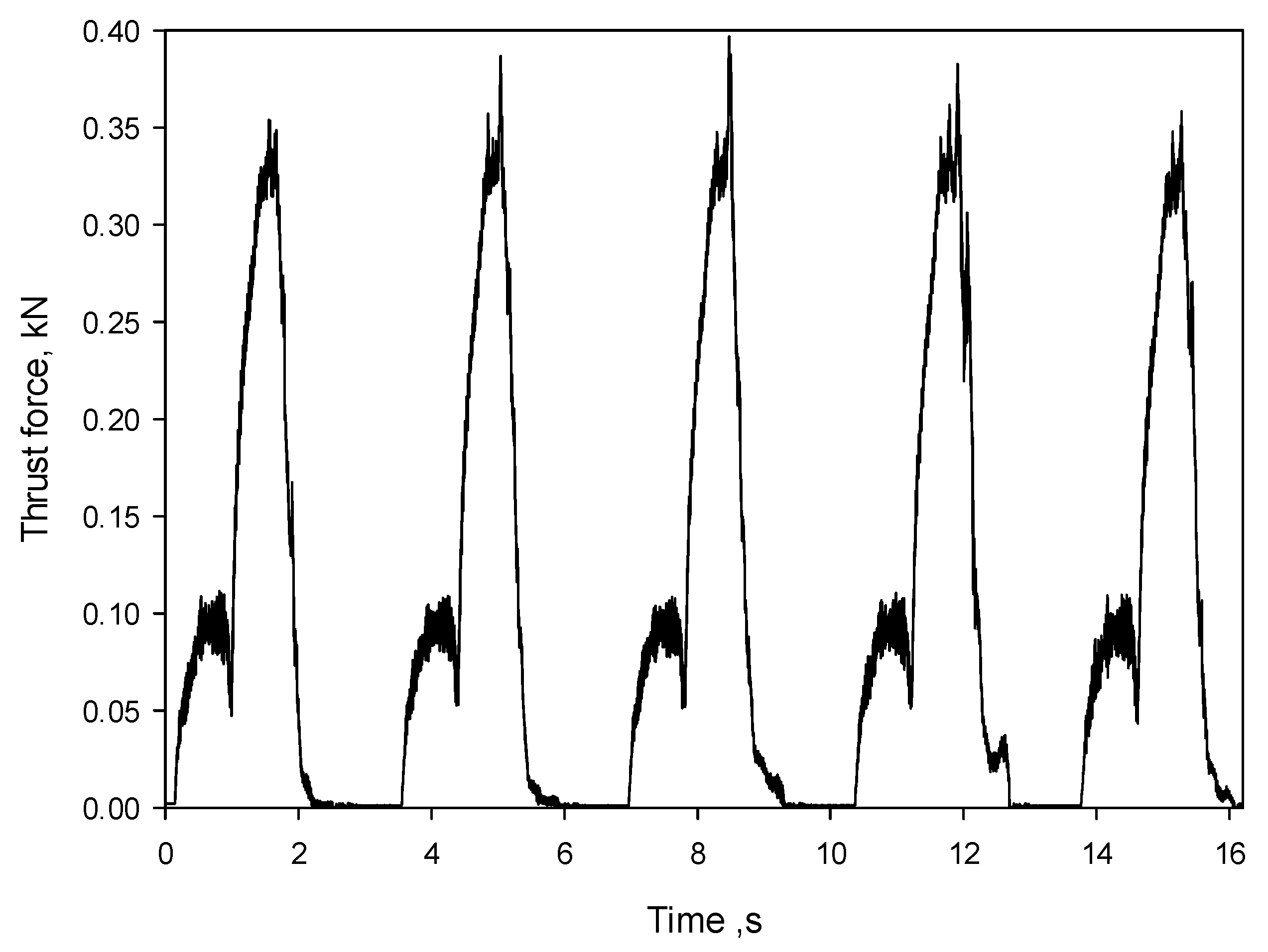
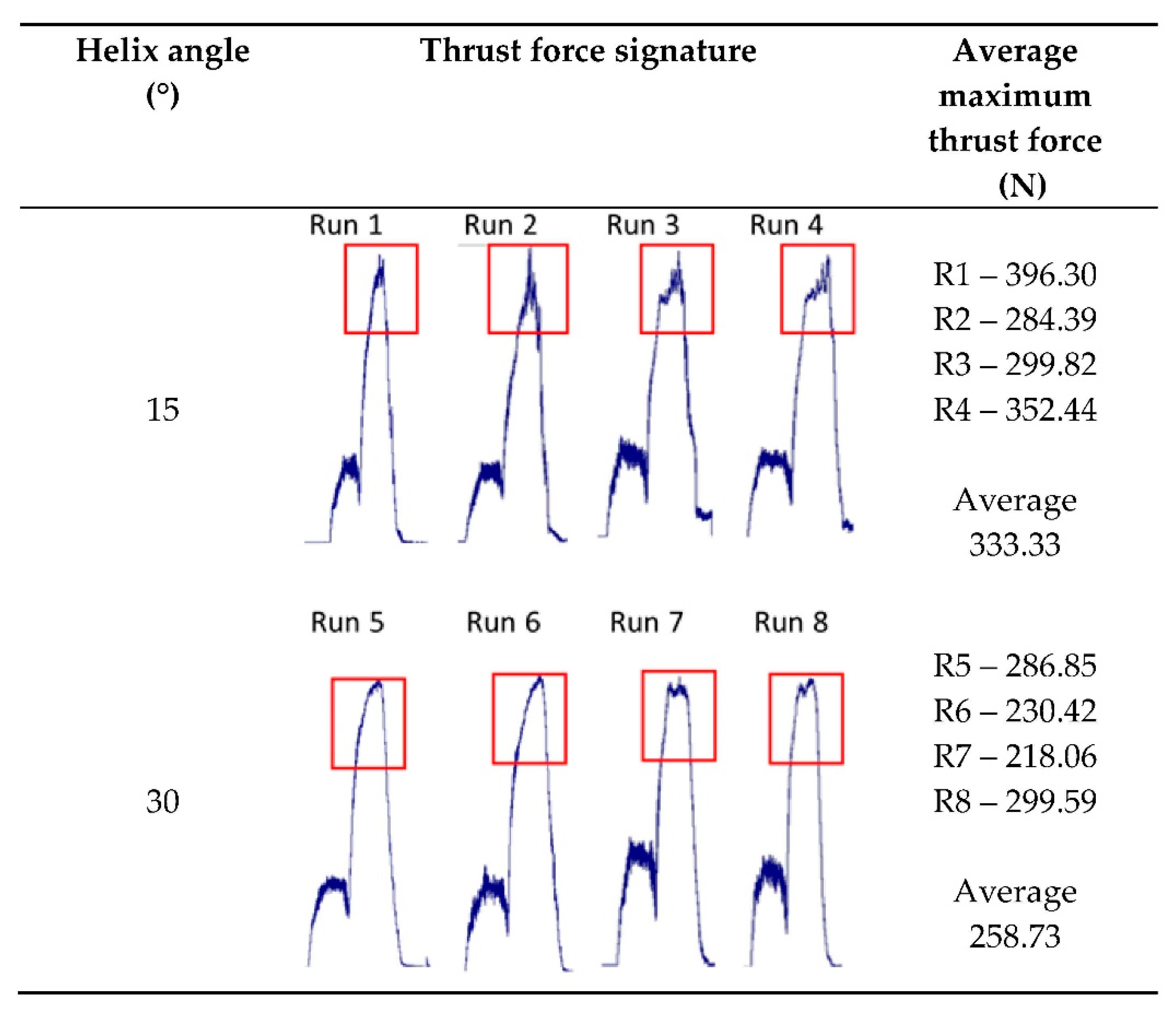
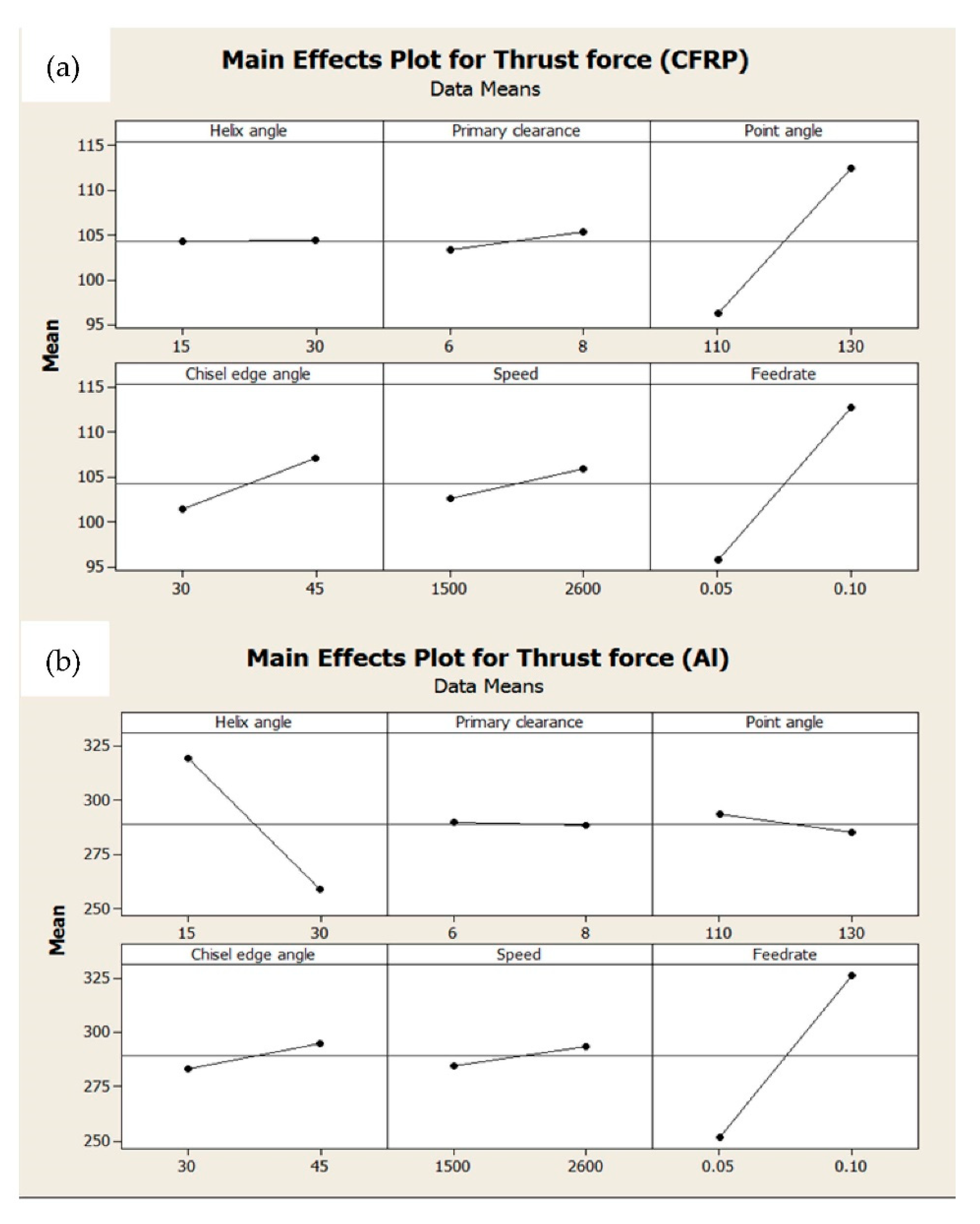
3.1. Thrust Force Analysis

Figure 2 shows the thrust force signature generated from dynamometer during the drilling of holes 1 to 5 for Run 1 (R1). The force signature represents a characteristic curve for the Al7075-T6 and CFRP layer as single-shot drilling took place. The maximum thrust force for each run is obtained by averaging the peak thrust force values of the five consecutive holes drilled. The thrust force of the aluminum plate (AL7075-T6) is proven to be two or three times higher than the thrust force of the CFRP panel based on Table 2. This result is in agreement with results in the literature [33]. This is due to the higher hardness of the aluminum panel (250 HV) compared to the carbon composites panel (180 HV) [34], resulting in lower impact on the fiber while drilling CFRP [35]. The thrust force of CFRP obtained from this experiment ranges from 87.69 N to 126.18 N, whereas for Al7075-T6, it varies between 218.21 N and 375.54 N. From the obtained result, R2 has the lowest CFRP peak thrust force, while R7 generates the lowest Al7075-T6’s peak thrust force value.
Through comparison of the thrust force signature generated from hole number 3, which represents an ideal condition of drilling process, it is observed that the trend of the thrust force signature produced during the drilling of Al7075-T6 differs between that of a helix angle of 15° (R1 to R4) and a helix angle of 30° (R5 to R8). Based on Figure 3, the thrust force signature from R1 to R4 fluctuate dramatically, causing a higher thrust force peak, with an average of 333.328 N. Meanwhile, the thrust forces generated from R5 to R8 have more stable fluctuation and a lower peak magnitude (average thrust force of 258.731 N), comparatively. The result proved that the helix angle is a significant factor affecting the thrust force of the aluminum panel.

3.2. Analysis of Variance

In order to further analyze the influence of parameters to the maximum thrust force of CFRP and Al7075-T6, respectively, the ANOVA technique is applied. The p-value calculated from ANOVA is used as an indicator to verify the optimal processing parameters which are statistically significant towards its responses, whereby the p-value of the model must not exceed 0.05, since a 95% confidence level is selected for the analysis. Based on the ANOVA result shown in Table 3 and Table 4, factors which significantly influence the maximum thrust force value for CFRP are feed rate (47.22%) and point angle (45.09%); meanwhile, for Al7075-T6, feed rate (58.4%) and helix angle (38.87%) contribute significantly to the maximum thrust force value. Furthermore, the aforementioned values of percentage of contribution show that feed rate has the strongest correlation to the thrust force value for both materials.
Main effect plot is applied alongside to study the effect of each parameter to the maximum thrust force value. As depicted in Figure 4, it is found that the lowest thrust force is generated during CFRP drilling with primary clearance angle of 6°, point angle of 110°, chisel edge of 30°, spindle speed of 1500 rev/min and feed rate of 0.05 mm/rev. Helix angle of 30°, point angle of 130°, chisel edge of 30°, speed of 1500 rev/min and feed rate of 0.05 mm/rev represent the optimum values found to obtain the lowest thrust force during Al7075-T6 drilling in the tested range. Meanwhile, the primary clearance angle appears to have no effect on CFRP and Al7075-T6, respectively.
The analysis of Figure 4 also indicates that a higher feed rate results in higher maximum thrust force for both CFRP and Al7075-T6. This is because a high feed rate increases the cutting depth per revolution, thus increasing the shear area of CFRP [36]. An increase in helix angle leads to a lower thrust force for Al7075-T6 while there is no effect for CFRP. This is associated to the increase in the rake angle on the lips, which consequently contributes to a better surface finish. As for CFRP, besides the feed rate, the point angle and chisel edge angle appear to significantly the peak thrust force value. A lower point angle and chisel edge angle will both result in a lower peak thrust force. A lower point angle is optimum for CFRP because of the non-homogenous behavior of CFRP. In addition, the point angle is a critical factor to CFRP because it is the first contact point that cuts the fibers and matrix at the drill hole wall [18]. It is more effective to cut the CFRP, which is stacked layer by layer using a more acute angle (110°) because the cutting area is smaller besides minimizing delamination damage [37]. As for the chisel edge angle, it is related to the cutting lips produced. At a lower chisel edge, the cutting lips produced are longer, leading to a more efficient cutting process.

3.3. Hole Integrity Analysis

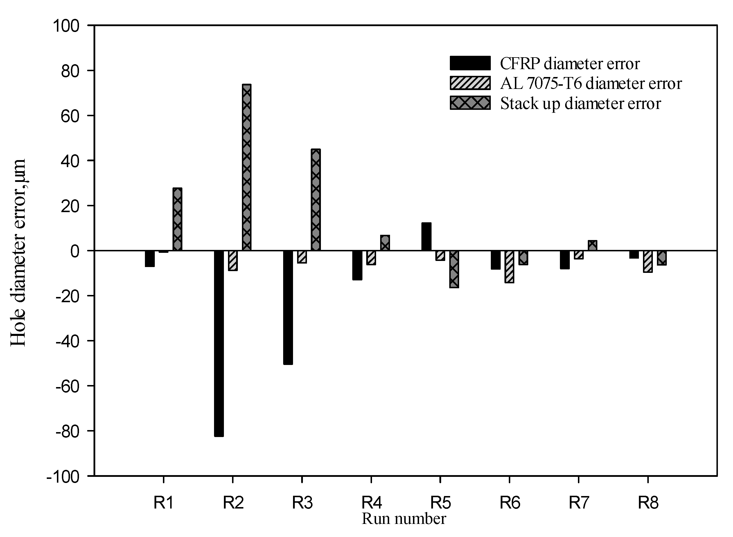
3.3.1. Hole Diameter Error

The hole diameter of the stacked-up materials are largely dependent on the selection of different tool geometries and parameters. The nominal diameter is the actual diameter of the drill bit before drilling. The measured diameter is the resulting hole diameter after the drilling process. The difference in the nominal and measured diameter for each hole was determined. The variation between hole diameter of CFRP and Al7075-T6 are also compared for each run. The comparisons are presented in Figure 5 below.
For R1, R2, R3, R4 and R7, the hole diameter error of CFRP is larger than Al7075-T6. This is largely associated with continuous chip formation. Continuous chip formation leads to chip clogging. Chips which are unable to be evacuated smoothly will remain in the hole and enlarge the CFRP holes. On the other hand, R5, R6 and R8 have larger hole diameters for Al7075-T6 compared to CFRP. This is mainly caused by the higher helix angle of 30°. A higher helix angle contributes to a higher lifting force to evacuate the chips. Therefore, the chips are able to evacuate properly and consistently. In comparison of all the runs, it is found that run R7 produced the minimum hole diameter error between Al7075-T6 and CFRP, emerging as the run with the optimum parameter combination for minimum hole diameter error.

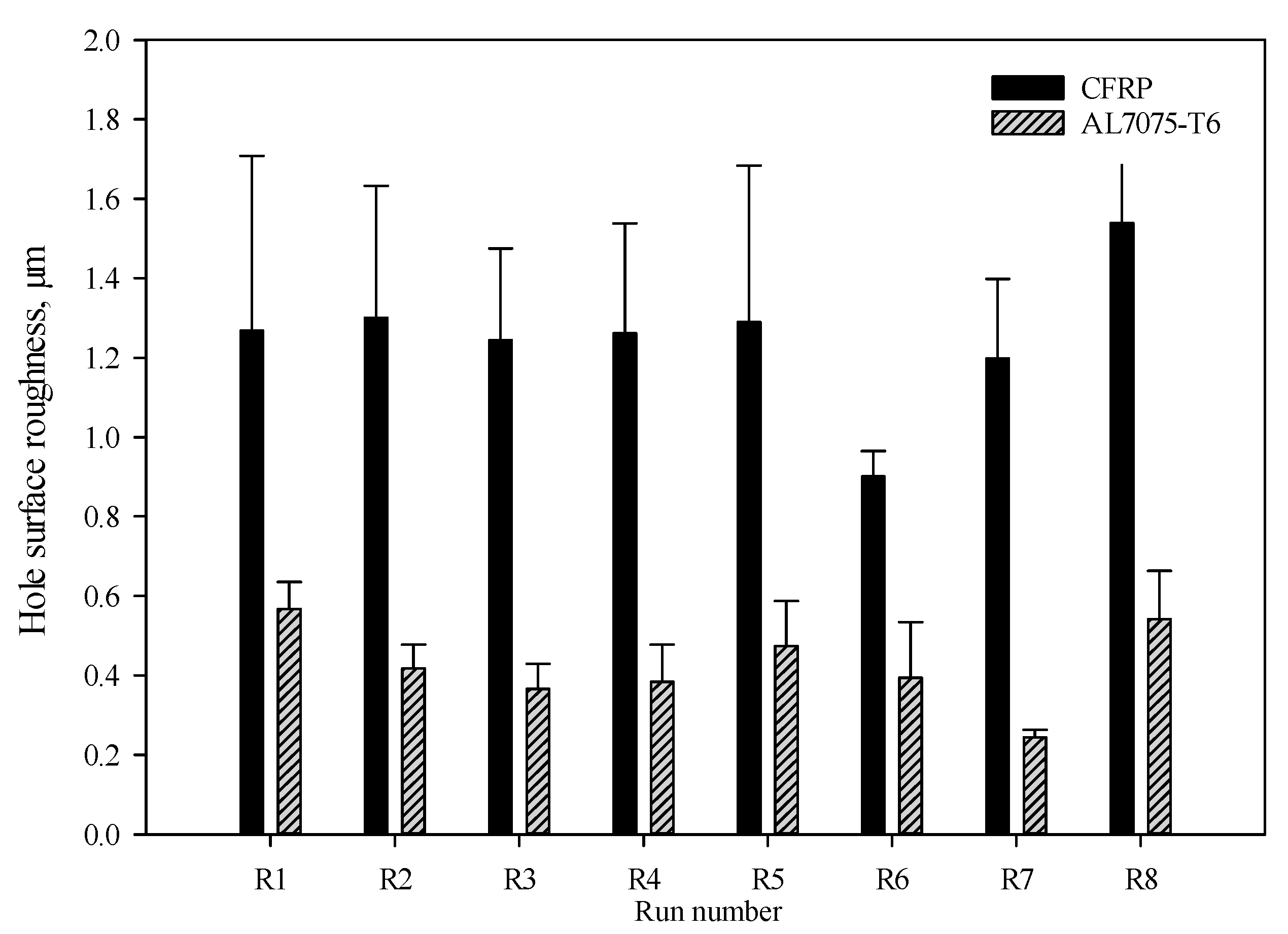
3.3.2. Hole Surface Roughness Analysis

Hole surface roughness is one of the evaluation methods of the hole quality of the stacked-up materials. The average surface roughness (Ra) was used as a measurement parameter in this study. In general, the acceptable surface roughness is an Ra value of CFRP and Al7075-T6 below 3 μm and 1 μm, respectively [35]. The hole surface roughness for both CFRP and Al7075-T6 for both runs are presented in Figure 6. Overall, the hole surface roughness values of CFRP and Al7075-T6 for all runs are within the acceptable range. In addition, R6 has the lowest CFRP hole surface roughness value, followed by R7, whereas R7 is recorded with the lowest Al7075-T6 hole surface roughness, followed by R3. However, surface roughness is not a sensitive method to select the optimum parameters, as all of the surface roughness values of all runs are still within the acceptable range.

3.4. Chip Formation Analysis

The chip shape and size are good indicators on the deformation occurring during the drilling process. With the usage of a twist drill of a fixed diameter, the chips produced while drilling Al7075-T6 in terms of its shape and size are highly associated to the chosen parameters. At a low spindle speed of 1500 rev/min, the shearing rate is low, causing chips to easily wind, and this results in a continuous long chip being formed. When the spindle speed increases to 2600 rev/min, the shearing speed is larger, resulting in wider chips. Chips became harder to wind because of the high stiffness and they break into smaller spiral pieces. In terms of feed rate, the value of 0.05 mm/rev is preferred due to the more consistent shape and size of the chips. At a lower feed rate, the shearing area is small and the chips can be evacuated at a smoother rate.
By comparing the chip formation during drilling at different feed rates and spindle speeds, as shown in Figure 7, it can be noticed that at a low speed and feed rate, continuous chips are produced, which in general reflect a higher surface roughness [21]. In other words, well-broken chips are preferable. As chips become longer, their movement through the flutes is less viable, which consequently leads to an increase in torque, temperature and a risk of drill breakage. At a speed of 2600 rev/min and feed rate of 0.05 mm/rev, the chip formation is optimum. Tight helical chips are formed as shown in R2 and the chips are serrated and fragmented into pieces, as in R7. When the chip is in a spiral cone chip, it is easier for them to be ejected, and hence, aid in the chip evacuation during drilling. In conclusion, short chips and tight helix chips are generally preferred to provide a better surface finish to the work-piece [38].

3.5. Comparison of Optimum Geometry to the Industry Standard

Through the analysis of maximum thrust force, hole diameter, hole surface roughness and chip formation, it is concluded that the best parameter for drilling stacked-up material is R7. The parameters selected are a helix angle of 30°, primary clearance angle of 6°, point angle of 130°, chisel edge angle of 30°, speed of 2600 rev/min and feed rate of 0.05 mm/rev. However, in the aerospace industry, the customer requirement for speed and feed rate are fixed at 2600 rev/min and 0.1 mm/rev, respectively, due to the concern of efficiency in terms of time. Thus, with the consideration of hole quality control, experiments using both parameter combinations are conducted and analyzed with similar methods, which is thrust force, surface roughness and hole diameter analysis. The results obtained are compared in Table 5 below.
It is justified that the study using a feed rate of 0.05 mm/rev produces better results compared to the study using a feed rate of 0.1 mm/rev, in terms of maximum thrust force, hole diameter and surface roughness. This is because a lower feed rate will cut through the material gradually at a smaller depth, giving a better surface finish. The formed chips, which are tighter and smaller in pieces, can be easily evacuated from the surface, thus improving the hole quality and the drilling process efficiency.

4. Conclusions

In this research, the drilling of stacked-up material of CFRP and Al7075-T6 using different drilling geometries and parameters was carried out. From the results, the following conclusions can be drawn.
  • From the eight runs, it is deduced that for drilling CFRP and Al7075-T6 stacked-up material, R7 has the best parameter combination, which includes a helix angle of 30°, primary clearance angle of 6°, point angle of 130°, chisel edge angle of 30°, speed of 2600 rev/min and feed rate of 0.05 mm/rev. This is supported by maximum thrust force, hole diameter error, surface roughness and chip formation analysis;
  • The range of thrust force which conforms to the diameter specification is 91.54 N to 103.45 N for CFRP and 218.21 N to 347.04 N for Al7075-T6;
  • For chip formation, the optimum parameters are found to be 2600 rev/min for spindle speed and 0.05 mm/rev for feed rate, whereby short broken chips and tight helical chips are formed. This aids the evacuation process during drilling, and hence provides a better surface finish;
  • By comparing the customer requirements and optimum parameters obtained in this study, it is concluded that feed rate of 0.05 mm/rev is preferable for better drilling performance. These conditions also allow one to produce desirable chips during drilling.

Author Contributions

Conceptualization, M.H.H. and J.A.; methodology, C.Y.S.; validation, M.H.H. and J.A.; formal analysis, C.Y.S.; investigation, C.Y.S.; writing—original draft preparation, M.H.H. and J.A.; writing—review and editing, R.M.; M.H.H. and G.F.; visualization, G.F.; supervision, J.A.; project administration, J.A. and M.H.H.; funding acquisition, J.A. All authors have read and agreed to the published version of the manuscript.

Funding

This research was funded by RUI, grant #1001/PMEKANIK/814288.

Institutional Review Board Statement

Not applicable.

Informed Consent Statement

Not applicable.

Data Availability Statement

Not applicable.

Acknowledgments

The authors would like to acknowledge the technical support from the School of Mechanical Engineering at USM.

Conflicts of Interest

The authors declare no conflict of interest.

References

  1. Gu, G.Y.; Kwon, D.J.; Wang, Z.J.; Kim, U.J.; Kim, I.H.; Kim, Y.S.; Park, J.M. Comparison of Optimum Drilling Conditions of Aircraft CFRP Composites using CVD and PCD Tools. In Proceedings of the 18th International Conference on Composite Materials, Jeju, Korea, 21–26 August 2011. [Google Scholar]
  2. Bañon, F.; Sambruno, A.; Fernandez-Vidal, S.; Fernandez-Vidal, S.R. One-shot drilling analysis of stack CFRP/UNS A92024 bonding by adhesive. Materials 2019, 12, 160. [Google Scholar] [CrossRef] [PubMed] [Green Version]
  3. Mahdi, A.; Turki, Y.; Habak, M.; Salem, M.; Bouaziz, Z. Experimental study of thrust force and surface quality when drilling hybrid stacks. Int. J. Adv. Manuf. Technol. 2020, 107, 3981–3994. [Google Scholar] [CrossRef]
  4. Yarar, E.; Karabay, S. Investigation of the effects of ultrasonic assisted drilling on tool wear and optimization of drilling parameters. CIRP J. Manuf. Sci. Technol. 2020, 31, 265–280. [Google Scholar] [CrossRef]
  5. Pardo, A.; Majeed, M.; Heinemann, R. Process signals characterisation to enable adaptive drilling of aerospace stacks. Procedia CIRP 2020, 88, 479–484. [Google Scholar] [CrossRef]
  6. El Bouami, S.; Habak, M.; Franz, G.; Velasco, R.; Vantomme, P. Effect of tool geometry and cutting parameters on delamination and thrust forces in drilling CFRP/Al-Li. AIP Conf. Proc. 2016, 1769, 080012. [Google Scholar]
  7. Leeflang, P.S.; Verhoef, P.C.; Dahlström, P.; Freundt, T. Challenges and solutions for marketing in a digital era. Eur. Manag. J. 2014, 32, 1–12. [Google Scholar] [CrossRef]
  8. Chu, N.H.; Nguyen, V.D.; Ngo, Q.H. Machinability enhancements of ultrasonic-assisted deep drilling of aluminum alloys. Mach. Sci. Technol. 2020, 24, 112–135. [Google Scholar] [CrossRef]
  9. Hou, G.; Qiu, J.; Zhang, K.; Cao, S.; Cheng, H.; Luo, B.; Cheng, Y. Comparative tool wear and hole quality investigation in drilling of aerospace grade T800 CFRP using different external cooling lubricants. Int. J. Adv. Manuf. Technol. 2020, 106, 937–951. [Google Scholar] [CrossRef]
  10. Jia, Z.Y.; Zhang, C.; Wang, F.J.; Fu, R. A mechanistic prediction model for thrust force and torque during drilling of CFRP/Ti stacks. Int. J. Adv. Manuf. Technol. 2020, 106, 3105–3115. [Google Scholar] [CrossRef]
  11. Ma, F.J.; Zhu, X.L.; Kang, R.K.; Dong, Z.G.; Zou, S.Q. Study on the subsurface damages of glass fiber reinforced composites. Adv. Mater. Res. 2013, 797, 691–695. [Google Scholar] [CrossRef]
  12. Van Grootel, A.; Chang, J.; Wardle, B.L.; Olivetti, E. Manufacturing variability drives significant environmental and economic impact: The case of carbon fiber reinforced polymer composites in the aerospace industry. J. Clean. Prod. 2020, 261, 121087. [Google Scholar] [CrossRef]
  13. Khanna, N.; Pusavec, F.; Agrawal, C.; Krolczyk, G.M. Measurement and evaluation of hole attributes for drilling CFRP composites using an indigenously developed cryogenic machining facility. Measurement 2020, 154, 107504. [Google Scholar] [CrossRef]
  14. Jia, Z.Y.; Chen, C.; Wang, F.J.; Zhang, C.; Wang, Q. Analytical model for delamination of CFRP during drilling of CFRP/metal stacks. Int. J. Adv. Manuf. Technol. 2020, 106, 5099–5109. [Google Scholar] [CrossRef]
  15. Phadnis, V.A.; Makhdum, F.; Roy, A.; Silberschmidt, V.V. Drilling in carbon/epoxy composites: Experimental investigations and finite element implementation. Compos. Part A Appl. Sci. Manuf. 2013, 47, 41–51. [Google Scholar] [CrossRef] [Green Version]
  16. Fernandes, M.; Cook, C. Drilling of carbon composites using a one shot drill bit. Part I: Five stage representation of drilling and factors affecting maximum force and torque. Int. J. Mach. Tools Manuf. 2006, 46, 70–75. [Google Scholar] [CrossRef]
  17. Qi, Z.; Zhang, K.; Cheng, H.; Liu, S. Numerical simulation for delamination during drilling of CFRP/AL stacks. Mater. Res. INNO 2015, 19, 98–101. [Google Scholar] [CrossRef]
  18. Heisel, U.; Pfeifroth, T. Influence of point angle on drill hole quality and machining forces when drilling CFRP. Procedia CIRP 2012, 1, 471–476. [Google Scholar] [CrossRef] [Green Version]
  19. Li, S.; Zhang, D.; Liu, C.; Tang, H. Exit burr height mechanistic modeling and experimental validation for low-frequency vibration-assisted drilling of aluminum 7075-T6 alloy. J. Manuf. Process. 2020, 56, 350–361. [Google Scholar] [CrossRef]
  20. Aamir, M.; Tu, S.; Tolouei-Rad, M.; Giasin, K.; Vafadar, A. Optimization and modeling of process parameters in multi-hole simultaneous drilling using taguchi method and fuzzy logic approach. Materials 2020, 13, 680. [Google Scholar] [CrossRef] [PubMed] [Green Version]
  21. Zitoune, R.; Krishnaraj, V.; Collombet, F. Study of drilling of composite material and aluminium stack. Compos. Struct. 2010, 92, 1246–1255. [Google Scholar] [CrossRef]
  22. Ahmed, Y.S.; Alam, M.S.; Arif, A.F.M.; Veldhuis, S.C. Use of acoustic emission and cutting force signals to monitor built-up edge formation in stainless steel turning. Int. J. Adv. Manuf. Technol. 2019, 103, 2257–2276. [Google Scholar] [CrossRef]
  23. Khanna, N.; Desai, K.; Sheth, A.; Larsen, J.Ø. CFRP machining on indigenously developing cryogenic machining facility: An initial study. Mater. Today Proc. 2019, 18, 4598–4604. [Google Scholar] [CrossRef]
  24. Montoya, M.; Calamaz, M.; Gehin, D.; Girot, F. Evaluation of the performance of coated and uncoated carbide tools in drilling thick CFRP/aluminium alloy stacks. Int. J. Adv. Manuf. Technol. 2013, 68, 2111–2120. [Google Scholar] [CrossRef] [Green Version]
  25. Zitoune, R.; Krishnaraj, V.; Collombet, F.; Le Roux, S. Experimental and numerical analysis on drilling of carbon fibre reinforced plastic and aluminium stacks. Compos. Struct. 2016, 146, 148–158. [Google Scholar] [CrossRef] [Green Version]
  26. Zitoune, R.; Cadorin, N.; Elambouacif, B.S.; Collombet, F.; Krishnaraj, V.; Bougherara, H. Influence of the double cone drill geometry on the holes quality during drilling multi-stack made of CFRP/Al. Int. J. Mater. Mech. Manuf. 2014, 2, 292–296. [Google Scholar]
  27. Zitoune, R.; Krishnaraj, V.; Almabouacif, B.S.; Collombet, F.; Sima, M.; Jolin, A. Influence of machining parameters and new nano-coated tool on drilling performance of CFRP/Aluminium sandwich. Compos. Part B Eng. 2012, 43, 1480–1488. [Google Scholar] [CrossRef]
  28. Neugebauer, R.; Ben-Hanan, U.; Ihlenfeldt, S.; Wabner, M.; Stoll, A. Acoustic emission as a tool for identifying drill position in fiber-reinforced plastic and aluminum stacks. Int. J. Mach. Tools Manuf. 2012, 57, 20–26. [Google Scholar] [CrossRef]
  29. Wertheim, R.; Ben-Hanan, U.; Ihlenfeldt, S.; Stoll, A.; Treppe, F.; Wabner, M. Acoustic emission for controlling drill position in fiber-reinforced plastic and metal stacks. CIRP Ann. 2012, 61, 75–78. [Google Scholar] [CrossRef]
  30. Wang, C.Y.; Chen, Y.H.; An, Q.L.; Cai, X.J.; Ming, W.W.; Chen, M. Drilling temperature and hole quality in drilling of CFRP/aluminum stacks using diamond coated drill. Int. J. Precis. Eng. Manuf. 2015, 16, 1689–1697. [Google Scholar] [CrossRef]
  31. Benezech, L.; Landon, Y.; Rubio, W. Study of manufacturing defects and tool geometry optimisation for multi-material stack drilling. In Advanced Materials Research; Trans Tech Publications Ltd.: Freienbach, Switzerland, 2012; Volume 423, pp. 1–11. [Google Scholar]
  32. Zhang, L.; Liu, Z.; Tian, W.; Liao, W. Experimental studies on the performance of different structure tools in drilling CFRP/Al alloy stacks. Int. J. Adv. Manuf. Technol. 2015, 81, 241–251. [Google Scholar] [CrossRef]
  33. El Bouami, S.; Habak, M.; Velasco, R.; Dos Santos, B.; Franz, G.; Vantomme, P. Tool geometry optimization for drilling CFRP/Ti6Al4V stacks with a lightning strike protection. AIP Conf. Proc. 2017, 1896, 090009-1–090009-6. [Google Scholar]
  34. Ashrafi, S.A.; Sharif, S.; Yazid, Y.M.; Davoudinejad, A. Assessment of Hole Quality and Thrust Force when Drilling CFRP/Al Stack Using Carbide Tools. In Applied Mechanics and Materials; Trans Tech Publications Ltd: Freienbach, Switzerland, 2012; Volume 234, pp. 28–33. [Google Scholar]
  35. Rahim, E.A.; Mohid, Z.; Hamzah, M.R.; Yusuf, A.F.; Rahman, N.A. Performance of tools design when helical milling on carbon fiber reinforced plastics (CFRP) aluminum (Al) stack. In Applied Mechanics and Materials; Trans Tech Publications Ltd.: Freienbach, Switzerland, 2014; Volume 465, pp. 1075–1079. [Google Scholar]
  36. Wei, Y.; An, Q.; Ming, W.; Chen, M. Effect of drilling parameters and tool geometry on drilling performance in drilling carbon fiber–reinforced plastic/titanium alloy stacks. Adv. Mech. Eng. 2016, 8, 1–16. [Google Scholar] [CrossRef] [Green Version]
  37. Gaitonde, V.N.; Karnik, S.R.; Achyutha, B.T.; Siddeswarappa, B. Methodology of Taguchi optimization for multi-objective drilling problem to minimize burr size. Int. J. Adv. Manuf. Technol. 2007, 34, 1–8. [Google Scholar] [CrossRef]
  38. SenthilKumar, M.; Prabukarthi, A.; Krishnaraj, V. Study on tool wear and chip formation during drilling carbon fiber reinforced polymer (CFRP)/titanium alloy (Ti6Al4 V) stacks. Procedia Eng. 2013, 64, 582–592. [Google Scholar] [CrossRef] [Green Version]
Figure 1. Experimental setup for drilling process and drill bits for Run 1 to 8.
Jcs 05 00189 g001
Figure 2. Thrust force signature for Run 1 (2600 rev/min, 0.1 mm/rev).
Jcs 05 00189 g002
Figure 3. Thrust force signature for Al7075-T6 panel at 15° and 30° helix angle.
Jcs 05 00189 g003
Figure 4. Main effect plot for the maximum thrust force (a) CFRP and (b) Al7075-T6.
Jcs 05 00189 g004
Figure 5. Hole diameter error of CFRP, Al7075-T6 and multi-material stack from R1 to R8.
Jcs 05 00189 g005
Figure 6. Comparison of hole surface roughness CFRP and Al7075-T6 from R1 to R8.
Jcs 05 00189 g006
Figure 7. Comparison of chip formation with varying spindle speed and feed rate.
Jcs 05 00189 g007
Table 1. Parameter combination based on fraction factorial design.
RunHelix
Angle
(°)
Primary Clearance
(°)
Point
Angle
(°)
Edge
Angle
(°)
Speed
(rev/min)
Feed
Rate
(mm/rev)
R11561104526000.1
R21581103026000.05
R31561304515000.05
R41581303015000.1
R53061103015000.1
R63081104515000.05
R73061303026000.05
R83081304526000.1
Table 2. Tabulation of maximum thrust force value of CFRP and Al7075-T6.
RunThrust ForceRatio
Fmax
CFRP
Fmax
Al7075-T6
R1109.6798375.54363.4
R287.6906281.68643.2
R3105.3568280.19422.7
R4118.6368347.03882.9
R599.8840289.83482.9
R691.5390227.85382.5
R7103.4484218.21042.1
R8126.1754300.09782.4
Table 3. Summary of ANOVA for maximum trust force for CFRP panel.
SourceSum of SquaredfMean SquareF Valuep-Value
Prob > F
Percentage of Contribution
Model1142.063380.6966.230.0007-
Point angle527.271525.2791.380.00745.09
Chisel edge point66.65166.6511.600.02715.72
Feed rate550.141550.1495.710.000647.22
Residual22.9945.75--1.97
Cor Total1165.067---100
Std Dev.2.40--0.9803-
Mean105.30-R² adjusted-0.9655-
C.V%2.28-R² predicted-0.9211-
PRESS91.97-Adequate precision-22.748-
Table 4. Summary of ANOVA for maximum trust force for Al7075-T6 panel.
SourceSum of SquaredfMean SquareF Valuep-Value
Prob > F
Percentage of Contribution
Model19,312.3129656.1589.090.0001-
Helix angle7716.9317716.9371.190.000438.87
Feed rate11,595.38111,595.38106.980.000158.40
Residual22.995108.39--2.552
Cor Total19,854.277---100
Std Dev.10.41--0.9727-
Mean290.06-R² adjusted-0.9618-
C.V%3.59-R² predicted-0.9301-
PRESS1387.41-Adequate precision-21.686-
Table 5. Comparison of maximum thrust force, hole surface roughness, hole diameter for feed rate 0.05 and 0.1 mm/rev.
CFRPAl7075-T6
Feed Rate (mm/rev)Ave. Thrust Force
(N)
Ave.
Surface Roughness
(µm)
Ave.
Hole
Diameter
(mm)
Ave. Thrust Force
(N)
Ave.
Surface Roughness
(µm)
Ave. Hole Diameter
(mm)
0.05103.740.2444.8265218.0081.19864.8221
--−0.008--−0.0036Nom.
--0.17--0.07Diff. (%)
0.1127.3020.85284.7975274.8941.61424.8368
--0.0225--−0.0168Nom.
--0.47--0.35Diff. (%)
Publisher’s Note: MDPI stays neutral with regard to jurisdictional claims in published maps and institutional affiliations.

